Load Cell Amplifier 5604058
- 格式:pdf
- 大小:239.42 KB
- 文档页数:16

Specification Approval Sheet Name:Polymer Lithium-Ion BatteryModel: CELLEVIA BATTERIES LP503040SPEC:3.7V/ 550mAhNumber: 503040Specification Modification RecordsContent1.Scope:This specification describes the Product Specification of chargeable Polymer Lithium-IonBattery produced by CELLEVIA BATTERIESAny copies are invalid without our company’s approval2.Model : CELLEVIA BATTERIES LP5030403.Cell parameters Index:3.2 Parameters of batterythe temperature.4.Electronic Characteristics test and inspection:4.1 Standard testing environmentUnless special stated, tests should be done within one month of delivery and thecharging-recharging times is less than 5 times. The following is test conditions: Ambient Temperature: 25℃±0.5℃Ambient Humidity: 65 ±20%4.2 The requirement of measure instrument(1) The measure instrument is passed tested by qualified institute.(2) The accuracy of the size instrument is not more than 0.01mm.(3) The accuracy of multimeter is not less than 0.5%. while measure the voltage, theinternal resistance mustn’t less than 10KΩ.(4) The principal of the internal resistance is 1KHz LCR, the accuracy is 0.2%.(5) The internal resistance is changeable, it varies according to the temperature and thecharging mode. And it is relevant to the PTC and the length and the Capacity of the drawing line.(6) The current accuracy of the battery test system is more than ±0.1%,is obaricallyaccuracy is ±0.5%, timer accuracy is less than ±0.1%.(7) The accuracy of the temperature meter is less than ±0.5℃.4.3 Visual inspectionAny visual inspection defects will affect the electronic characteristics, such as cracks,leakage, and flaw, are not inexistence.Page 3 of 9Notes: The Max. voltage while charging is not more than 4.25V.The Max.protective voltage designed on PCB board should not more than4.3V.5. Storage and others5.1 Long Period StorageIf the cell has been stored for 3 month, it should be transfer to a dry and cool environment. Storage Voltage is between 3.6V and 3.9V and the storage conditions as Item 4.1.5.2Any matters that this specification does not cover should be conferred between thecustomer and CELLEVIASpecification Approval sheet6.Drawing6.1 Assembly diagram(not in scale)Model :LP50304031.0MAX30adhesive wire black AWG2660wire red (+)AWG2650703040550m A hconnector JST E V I A B A T T E R I E S 3,7 V! Danger●Strictly prohibits heat or throw cell into fire.●Strictly prohibits throw and wet cell in liquid such as water, gasoline or drink etc.●Strictly prohibits use leave cell close to fire or inside of a car where temperature may be above60°C. Also do not charge / discharge in such conditions.●Strictly prohibits put batteries in your pockets or a bag together with metal objects such asnecklaces. Hairpins,coins, or screws. Do not store or transportation batteries with such objects.●Strictly prohibits short circuit the (+) and (-) terminals with other metals.●Do not place Cell in a device with the (+) and (-) in the wrong way around.●Strictly prohibits pierce Cell with a sharp object such as a needle.●Strictly prohibits disassemble or modify the cell.●Strictly prohibits welding a cell directly.●Do not use a Cell with serious scar or deformation.●Thoroughly read the user’s manual before use, inaccurate handling of lithium ion rechargeablecell may cause leakage, heat, smoke, an explosion, or fire, capacity decreasing.! Warning●Strictly prohibits put cell into a microwave oven, dryer, or high-pressure container.●Strictly prohibits use cell with dry cells and other primary batteries, or new and old battery orbatteries of a different package, type, or brand.●Stop charging the Cell if charging is not completed within the specified time.●Stop using the Cell if abnormal heat, odor, discoloration, deformation or abnormal condition isdetected during use, charge, or storage.●Keep away from fire immediately when leakage or foul odor is detected.●If liquid leaks onto your skin or clothes, wash well with fresh water immediately.●If liquid leaking from the Cell gets into your eyes, do not rub your eyes. Wash them well with cleanedible oil and go to see a doctor immediately.! Caution●Before using the Cell, be sure to read the user’s manual and cautions on handling thoroughly.●Charging with specific charger according to product specification. Charge with CC/CVmethod. Strictly prohibits revered charging. Connect cell reverse will not charge the cel. Atthe same time, it will reduce the charge-discharge characteristics and safety characteristics,this will lead to product heat and leakage.●Store batteries out of reach of children so that they are not accidentally swallowed.●If younger children use the Cell, their guardians should explain the proper handling.●Before using the Cell, be sure to read the user’s manual and cautions on handling thoroughly.●Batteries have life cycles. If the time that the Cell powers equipment becomes much shorter thanusual, the Cell life is at an end. Replace the Cell with a new same one.●When not using Cell for an extended period, remove it from the equipment and store in aplace with low humidity and low temperature.●While the Cell pack is charged, used and stored, keep it away from objects or materials with staticelectric charges.●If the terminals of the Cell become dirty, wipe with a dry clothe before using the Cell.●Storage the cells in storage temperature range as the specifications, After full discharged, wesuggest that charging to 3.9~4.0V with no using for a long time.●Do not exceed these ranges of the following temperature ranges.Charge temperature range : 0 °C to 45 °C;Discharge temperature range : -20 °C to 60 °C.(When using equipment)Handling Precaution and GuidelineFor LIP (Lithium-Ion Polymer) Rechargeable BatteriesPrefaceThis document of ‘Handling Precautions and Guideline LIP Rechargeable Batteries’shall be applied to the battery cells manufactured by Cellevia.Note (1): The customer is requested to contact Cellevia in advance, if and when the customer needs other applications of operating conditions than those described in this document. Additional experimentation may be required to verify performance and safety under such condition.Note (2): Cellevia will take no responsibility for any accident when the cell is used under other condition.Note (3): Cellevia will inform, in a written form, the customer of improvement(s) regarding proper use and handling of the cell, if it is deemed necessary.1. Charging 1.1ChargingCurrent:Charging current should be less than maximum charge current specified in theSpecification Approval Sheet.1.2 Charging Voltage:Charging voltage should be less than the maximum nominal voltage 4.2V, andthe charging voltage upper limited is 4.30V(single pack).1.3 Charging Temperature:The cell should be charged within the range specified in this SpecificationApproval Sheet.1.4 Notes:Since charging with constant current or constant voltage, reverse charging isprohibited. In case of the cell is connected improperly, the cell cannot be charged.Simultaneously, the reverse charging may cause damaging to the cell whichmay lead to degradation of cell performance and damage the cell safety, andcould cause heat generation or leakage.2. Discharging Current:The cell shall be discharged at less than the maximum discharge current specified in the Specification Approval Sheet. High discharging current may reduce the discharging capacity significantly or cause over-heat.3. Discharging TemperatureDischarging Temperature should be within the range specified in this Specification Approval Sheet.4.Over-DischargeOver-discharging will cause cell low-performance and function loss. The cell would be in a over-discharged state by its self-discharge characteristic. In order to prevent over-discharging, the cell shall be charged periodically to maintain between 3.6V and 3.9V.5. Protective Circuit Module5.1 The cell / battery pack shall be with a PCM that can protect cell / battery packproperly. PCM shall have functions of(1) Overcharging prevention(2) Over-discharging prevention(3) Over current prevention to maintain safety and prevent significant deteriorationof cell performance. The over current can occur by external short circuit.5.2 Overcharging ProtectionOvercharging prevention function shall stop charging if any cell of the battery packreaches 4.30V.5.3 Over-discharging protectionOver-discharging protection function shall monitor the voltage of every cell in the pack, and work to avoid further drop in the cell voltage of 2.5V or less.6. StorageCells should be stored in proper temperature specified in Specification ApprovalSheet.7. AppearanceIt shall be free from any defects such as remarkable scratches, breaks, cracks,discoloration, leakage or deformation .8. Notice△!8.1 Handling of cells:Avoid any short-circuit, it will caused the pole hot and lost electronic functions.Soft packing is very damaged by sharp edge parts such as needles and knives.Avoid cells touch with sharp edge part, when handling and storage.Beside the poles is the sealed edge. Don’t bend or fold dealing edge, for it is a sensitive part.Don’t open the folding edge on both sides of the cells.Don’t bend the tabs, for the tabs are not so stubborn.Avoid mechanical shock to the cells.Don’t put the cells into the heater, washing machine or high-voltage container.Don’t use the charger without any safety guarantee, and recommend you use specified charger.You should immediately stop charging, as cell is overheating, delivery any smell, changed color, distortion etc.Before Children use batteries, adults should explain the usage first.Before use batteries, please read the handling guideline carefully and fully understand.Away from the static-electronic field, while using, charging and storing cells.Don’t put the cells together with metal conductors such as chains, barrette, bolt into the pocket or stored them together.Don’t use metal conductor to shortcut the positive and negative poles.Don’t mis-assemble the positive pole with the negative one.8.2 Notice for Designing Battery Pack8.2.1 Package DesignBattery pack should have sufficient strength and battery should be protected from mechanical shock.No sharp edge components should be inside the pack containing the battery.8.2.2 PCM DesignThe overcharge threshold voltage should not be exceed 4.30V (single pack)The over-discharge threshold voltage should not be lower than 2.5V (single pack)The PCM should have short protection built inside.8.3 Notice for Assembling Battery Pack8.3.2 Tab connectionUltrasonic welding or spot welding is recommended to connect battery with PCM or other parts.If apply manual solder method to connect tab with PCM, below notice is very important to ensure battery performance.8.3.2.1 The solder iron should be temperature controlled and ESDsafe.8.3.2.2 Soldering temperature should not exceed 350℃.8.3.2.3 Soldering time should not be longer than 3 seconds .8.3.2.4 Keep battery tab cold down before next time soldering.8.3.2.5 Directly heat cell body is strictly prohibited. Battery shouldbe damaged by heat above approx. 60℃.8.3.3 Cell fixingThe battery should be fixed to the battery pack by its large surface area.No sharp edge at the assembling position.No cell movement in the battery pack should be allowed.9.Others9.1 The disassembling may generate internal shout circuit in the cell, which may causegassing, firing, or other problem.9.2 Prohibition of dumping of cells into fireNever incinerate or dispose the cells in fire, for these may cause firing of the cells.9.3 The cells should never be soaked with liquids such as water, drinks or oil.9.4 Prohibit using the cells mixed with different manufactories. Prohibit using new cellsmixed with old ones.▲Special Notice: If the cell isn’t used for a long time, Please Keep the cells in half-charged state, which is keeping them unfully charged or incompletely discharged. Recharge the cells and use half of the power after 2-3months. Store the cells in cool and dry place. It will protect the cell from damage effectively and long-term.10. StatementIf our specifications material, product process or product control system has changed, the information will be transmitted to consumer by way of written with quality and reliability data.。

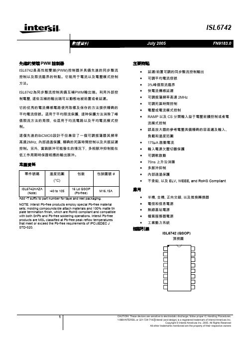
®1CAUTION: These devices are sensitive to electrostatic discharge; follow proper IC Handling Procedures.1-888-INTERSIL or 321-724-7143|Intersil (and design) is a registered trademark of Intersil Americas Inc.Copyright © Intersil Americas Inc. 2005. All Rights ReservedAll other trademarks mentioned are the property of their respective owners先進的雙端PWM 控制器ISL6742是高性能雙端(PWM)控制器并具備先進的同步整流控制以及限流臨界的特點。
它能用于電流以及電壓模式控制方法。
ISL6742為同步整流控制具備互補PWM輸出端。
利用外部控制電壓, 這些互補的輸出端可以動態地被前置或者延遲。
它的优秀的電流傳感電路使用取樣及保存的方法提供精确的平均電流信號。
适用于平均限流保護, 這种保護方法消除了峰值限流方法的局限, 也适用于均流電路以及平均電流模式控制。
這個先進的BiCMOS設計不但兼容了一個可調振蕩器其頻率高達2MHz, 內部過溫保護, 精确的死區時間控制以及共振延遲控制。
另外, 當跳脈沖可能發生的情況下, 多相脈沖抑制能在低工作周期時保證相應的輸出脈沖。
定購資料零件號碼溫度范圍(°C)包裝 包装圖號 #ISL6742AAZA(Note)-40 to 10516 Ld QSOP (Pb-free)M16.15AAdd -T suffix to part number for tape and reel packaging.NOTE: Intersil Pb-free products employ special Pb-free material sets; molding compounds/die attach materials and 100% matte tin plate termination finish, which are RoHS compliant and compatible with both SnPb and Pb-free soldering operations. Intersil Pb-free products are MSL classified at Pb-free peak reflow temperatures that meet or exceed the Pb-free requirements of IPC/JEDEC J STD-020.主要特點• 延遲/前置可調的同步整流控制輸出 • 可調平均電流信號 • 3%峰值限流臨界 • 快電流傳感延遲• 可調振蕩頻率高達2MHz • 可調死區時間控制 • 電壓或電流模式控制• RAMP 以及CS 分開輸入益于電壓前饋控制或者電流模式控制• 誤差放大器的參考電壓具備精确的容差遍及輸入、負載和溫度范圍 • 175µA 啟動電流 •輸入電源欠壓切斷保護 • 可調軟啟動 •70ns 上升沿消隱 •多脈沖抑制 • 內部過溫保護•不含鉛, 以及ELV, WEEE, and RoHS Compliant應用• 半橋, 全橋, 正向交錯, 以及推挽轉換器 • 電信和信息電源 • 無線基站電源 • 檔案服務器電源 •工業動力系統插腳引線ISL6742 (QSOP)頂視圖OUTAN OUTBNOUTAOUTBIOUTCTRTDVDDGNDVREFVERRFBSSCSVADJRAMP內部電路結构典型應用電路 – 電信原邊半橋式同步整流轉換器VIN-典型應用電路 – 高壓輸入次邊控制ZVS全橋轉換器VIN-額定值Supply Voltage, VDD ----------------GND - 0.3V to +20.0V OUTxxx ------------------------------------GND - 0.3V to VDD Signal Pins-------------------------GND - 0.3V to V REF +0.3V VREF ---------------------------------------GND – 0.3V to 6.0V Peak GATE Current-----------------------------------------0.1A ESD ClassificationHuman Body Model (Per MIL-STD-883 Method 3015.7)------2000V Charged Device Model (Per EOS/ESD DS5.3, 4/14/93)-------1000V 運行條件Supply Voltage Range (Typical)------------------9V-16VDC Temperature RangeISL6742AAxx-------------------------------40o C to 105o C 熱性能的資料Thermal Resistance Junction to Ambient (Typical) θJA (o C/W) 16 Lead QSOP (Note 1)-------------------------------------95 Maximum Junction Temperature -------------------55o C to 150o C Maximum Storage Temperature Range-----------65o C to 150o C Maximum Lead Temperature (Soldering 10s)--------------300o C (QSOP – Lead Tips Only)CAUTION: Stress above those listed in “Absolute Maximum Ratings” may cause permanent damage to the device. This is a stress only rating and operation of thedevice at these or any other conditions above those indicated in the operational section of this specification is not implied.Notes:1) θJA is measured with the component mounted on a low effective thermal conductivity test board in free air. See Tech Brief TB379 fordetails.2) All voltages are with respect to GND.Electrical SpecificationsRecommended Operating Conditions, Unless Otherwise Noted. Refer to Block Diagram and Typical Application Schematic.9V < V DD < 20V, RTD = 10.0kΩ, CT = 470pF, T A = -40o C to 105o C (Note 3), Typical values are at T A= 25o C.PARAMETER TESTCONDITIONSMINTYPMAXUNITS SUPPLY VOLTAGESupply Voltage - - 20 VStart-Up Current, I DD VDD= 5.0V -175400µAOperating Current, I DD R LOAD, C OUT = 0 - 7.5 12 mAUVLO START Threshold 8 8.75 9 VUVLO STOP Threshold 6.5 7 7.5 VHysteresis - 1.75 - VREFERENCE VOLTAGEOverall Accuracy I VREF = 0 - 10mA 4.85 5 5.15 VLong Term Stability TA = 125°C, 1000 hours (Note 4) - 3 - mVOperational Current (source) -10 - - mAOperational Current (sink) 5 - - mACurrent Limit VREF = 4.85V -15 - -100 mACURRENT SENSECurrent Limit Threshold VERR = VREF 0.97 1 1.03 VCS to OUT Delay Excl. LEB (Note 4) - 35 50 nsLeading Edge Blanking (LEB) Duration (Note 4) 50 70 100 nsCS to OUT Delay + LEB T A = 25°C - - 130 nsCS Sink Current Device Impedance V CS = 1.1V - - 20 ΩInput Bias Current V CS = 0.3V -1.0 - 1.0 µA 電气規范Electrical Specifications電气規范Recommended Operating Conditions, Unless Otherwise Noted. Refer to Block Diagram and Typical Application Schematic.9V < V DD < 20V, RTD = 10.0kΩ, CT = 470pF, T A = -40o C to 105o C (Note 3), Typical values are at T A= 25o C. (continued)MAXTYPUNITS PARAMETER TESTCONDITIONSMINIOUT Sample and Hold Buffer AmplifierT A = 25°C 4 4.09 4.15 V/VGainIOUT Sample and Hold VOH V CS = 1.00V, I LOAD = -300µA 3.9 - - VIOUT Sample and Hold VOL V CS = 0.00V, I LOAD = 10µA - - 0.3 VRAMPRAMP Sink Current Device Impedance V RAMP = 1.1V - - 20 ΩRAMP to PWM Comparator Offset T A = 25°C 65 80 95 mVBias Current V RAMP = 0.3V -5 - -2 µAClamp Voltage (Note 4) 6.5 - 8 VSOFT-STARTCharging Current SS = 3V -60 -70 -80 µASS Clamp Voltage 4.41 4.5 4.59 VSS Discharge Current SS = 2V 10 - - mAReset Threshold Voltage T A = 25°C 0.23 0.27 0.33 VERROR AMPLIFIERInput Common Mode (CM) Range (Note 4) 0 - VREF VGBWP (NoteMHz-4) 5-VERR VOL I LOAD = 2mA - - 0.4 VVERR VOH I LOAD = 0mA 4.2 - - VVERR Pull-Up Current Source VERR = 2.50V 0.8 1 1.3 mAEA Reference TA = 25°C 0.594 0.6 0.606 VEA Reference + EA Input Offset Voltage 0.59 0.6 0.612 VPULSE WIDTH MODULATORMinimum Duty Cycle VERR < 0.6V - - 0 %VERR = 4.20V, V RAMP = 0V, V CS = 0V94 %(Note 5)Maximum Duty Cycle (per half-cycle)RTD = 2.00kΩ, CT = 220pF- 97 - %RTD = 2.00kΩ, CT = 470pF - 99 - %Zero Duty Cycle VERR Voltage 0.85 - 1.2 VVERR to PWM Comparator Input Offset T A = 25°C 0.7 0.8 0.9 VVERR to PWM Comparator Input Gain 0.31 0.33 0.35 V/VCommon Mode (CM) Input Range (Note 4) 0 - 4.45 VOSCILLATORFrequency Accuracy, Overall(Note 4) 165 183 201 kHz%10-10-%0.3Frequency Variation with VDD T A = 25°C, (F20V- - F10V)/F10V -1.7VDD = 10V, |F-40°C - F0°C|/F0°C- 4.5 - %Temperature Stability|F0°C – F105°C|/F25°C (Note 4) - 1.5 - %Electrical SpecificationsRecommended Operating Conditions, Unless Otherwise Noted. Refer to Block Diagram and Typical Application Schematic.9V < V DD < 20V, RTD = 10.0k Ω, CT = 470pF, T A = -40oC to 105oC (Note 3), Typical values are at T A = 25oC.Charge Current T A = 25°C, V CS = 1.8V -193 -200 -207 µA Discharge Current Gain19 21 23 µA/µA CT Valley Voltage Static Threshold 0.75 0.8 0.88 V CT Peak Voltage Static Threshold 2.75 2.8 2.88 V CT Pk-Pk Voltage Static Value 1.92 2 2.05 V RTD Voltage1.9722.03VOUTPUTHigh Level Output Voltage (VOH) I OUT = -10mA, VDD - VOH - 0.5 1 V Low Level Output Voltage (VOL) I OUT = 10mA, VOL - GND- 0.5 1 V Rise Time C OUT = 220pF, VDD = 15V (Note 4) - 110 200 ns Fall TimeC OUT = 220pF, VDD = 15V (Note 4) - 90 150 ns UVLO Output Voltage ClampVDD = 7V, I LOAD = 1mA (Note 6) - - 1.25 VV ADJ = 2.50V (Note 4) - - 3 ns V ADJ < 2.425V -40 - -300 nsOutput Delay/Advance RangeOUTAN/OUTBN relative to OUTA/OUTBV ADJ > 2.575V40 - 300 ns Delay Control Voltage RangeOUTAN/OUTBN relative to OUTA/OUTB OUTxN Delayed2.575-5VOUTx Delayed 0 - 2.425 VT A = 25°C (OUTx Delayed)VADJ = 0 280 300 320 ns VADJ = 0.5V 92 105 118 ns VADJ = 1.0V 61 70 80 ns VADJ = 1.5V 48 55 65 ns VADJ = 2.0V41 50 58 ns T A = 25°C (OUTxN Delayed) VADJ = VREF 280 300 320 ns VADJ = VREF - 0.5V 86 100 114 ns VADJ = VREF - 1.0V 59 68 77 ns VADJ = VREF - 1.5V 47 55 62 ns VADJ Delay TimeVADJ = VREF - 2.0V41 48 55 ns THERMAL PROTECTIONThermal Shutdown (Note 4) 130 140 150 °C Thermal Shutdown Clear (Note 4) 115 125 135 °C Hysteresis, Internal Protection (Note 4)-15-°CNOTES:3. Specifications at -40oC and 105 oC are guaranteed by 25 oC test with margin limits. 4. Guaranteed by design, not 100% tested in production.5. This is the maximum duty cycle achieveable using the specified values of RTD and CT. Larger or smaller maximum duty cycles may beobtained using other values for these components. See Equation 1-3. 6. Adjust VDD below the UVLO stop threshold prior to setting at 7V.電气規范各管腳簡介VDDVDD是控制器的電源輸入端。

Getting started with the Statox 5601Safety Advice∙Read and observe this manual carefully. Store it in a safe place.∙The Statox 560 must not be operated other than in the specified ambient conditions (see Technical Data, page 10).∙In particular the regulations with regards to the protection regulations for instance DIN EN 60079-14 must be observed.∙Installation must be performed by trained and authorized personnel. Only original Compur Monitors parts may be used.∙The Statox 560 must not be connected to mains! The supply voltage is 24 (16-30) VDC.∙All outputs of the Statox 560 may only be operated with 30 VDC.∙Damaged or modified sensor heads must not be used.∙The Ex d housing must not be opened!∙When operated in hazardous atmosphere, the sensor head must be connected to the exLink counterpart or to a certified connection box.Disregarding these recommendations may compromise the Ex protection and result in a danger for personnel and assets.2 InstallationLeaving the stainless steel protective cylinder and the protective cap on the instrument protects it from pollution.Install the Statox 560 sensor head in upright position to the wall. Use two M8 screws and suitable washers. Compur Monitors offers an Ex e rated terminal box (art. # 562988) made of varnished cast aluminum.Picture 1: Statox 560 dimensions in mm and the space needed for safe and easy operation.Outer dimensions and drill plan of the junction box, article number 562988.Do not open the blue flame - proof housing!Ø 8,33 Connection3.1 Statox 560 Cable Tail Version ConnectionThe cable tail must be connected to a suitable EMC junction box made of metal. When installed in a hazardous area this must be certified Ex e and have 10 terminals and EMC resistant cable glands. Compur Monitors recommends to use fine mashed cable ≥ 0.75 mm² for instance type Oelflex 415 CP.Statox 560 must be operated with 24 (16-30) VDC. Connecting it to higher voltages or shortcircuiting the outputs may destroy it.Picture 2: Statox 560 cable tail connectionCaution:A. Connect the grounding contact to the ground of the building, using a cable diameter ≥ 6 mm².B. Remove the protective tube from the cable shield and insert the cable through the EMC – proof cablegland. Remark: the cable shield is not connected to the sensor head housing!C. Connect the cores in the sequence of their numbers to the terminals, the white core to terminal 10. Allcores must be connected, even if you do not use them all.D. Connect the grounding contact of the junction box to the ground of the building. Use a cable with ≥ 4mm² diameter.E. The number of outgoing cable glands depends on your application.ABDCE∙ Do not try to remove the cable tail from the sensor head. It will destroy it! ∙ Never leave lose cable ends in the terminal box!∙ Proper grounding is essential for error – free operation!3.2 Statox 560 connecting the eXLink-PlugThe Statox 560 eXLink-Version (7 pole) has a plug installed in the housing. The counterpart must beinstalled by the user and can be connected to a junction box if necessary. The eXLink can be connected and disconnected in hazardous areas without hot work permit.Picture 3: Connection of the eXLinkADBCEPlease observe points A to E in chapter 3.1, they apply to this application method, too. It is not mandatory to connect all contacts on the field side.Do not connect the cable shield to the coupling!Use only coupling Compur Art. # 805594. Observe its installation instructions.∙ Take care for correct wiring! Wrong pin assignment may damage the Statox 560!∙Do not try to dismount the eXLink from the sensor head. This is a potted joint.Loosening it will destroy Ex d rating of the housing!Pin assignment:4KeysStatox 560 can be operated through the window with a magnetic pin. The magnetic pin activates hall sensors inside the sensor head. Just hold the slim part of the pin next to the key. The individual keys have the following functions:KeysPicture 4:Pin assignment eXLink-plug5 Getting started and menu navigationRemove the yellow protective cap and unscrew counterclockwise the stainless steel protection cylinder. If there is a short circuit bridge at the sensor module (applicable for 2 electrode sensors) remove it. Insert the guiding pins into the relevant drill holes to connect the sensor module by pushing it carefully upward (see picture 5).Picture 5: Connecting the sensor moduleNow fingertight fasten the protection cylinder. The sealing ring must be clean!The warm-up procedure (see picture 6) can take some minutes, especially with 3-electrode-sensors. After the warm-up, the Statox 560 will go into the measuring mode.The following settings must be done after the start-up:∙ Set the real time clock∙ Set the self-test parameters ∙ Set the alarm relaysChange the sensor module only in the menu Change Sensor in order to avoid a data loss in the sensor memory.The following schematics show the warm-up and an overview of the main menu of the Statox 560 with a short description. Hint:When the symbol ✱ appears on right upper side of the display, internal diagnostics are made. During thistime, the buttons are not active and there is no display update!Sealing ringPicture 6: Schematics warm-upPicture 7: Main menuProoftestSelftest Calibration Change SensorErrors Info Alarm History Sensor InfoTemperature Firmware Alarm RelaysReal Time ClockService Output Function TestMaintenance6System StatusIf the display is dark and green LED off, the power supply voltage is off, too low or its polarity is wrong. If none of this is the case, a burned out fuse might be the reason.!Replacement of the fuse must be done by Compur Monitors!1)Program in menu Service Output.2)If an alarm has been set to AUTO RESET, the actual status is displayed. If it has been set to HOLD, the last alarm status will stay.To delete a latching alarm press the Reset- Button.3)Ex works setting, can be changed by user.4)Alarm output active means the open collector output is current fed. The SF output is always active in order to detect apotential power outage.5)Periodic double flash every 5 seconds.6)Ex works setting, can be changed by user.7)No ex works setting, can be set by user. The SF Relay is passive in this mode, to differentiate from the 4-20 mA in themeasuring mode.8)The measured value alternates with the message …Zero adjustment failed“ or…Calibration failed” in case any of theseprocedures has failed.7 Technical DataProduct name: Statox 560 Type: 5377 Manufacturer: COMPUR Monitors GmbH & Co. KG, Weissenseestr. 101, D-81539 Munich Power supply: 24 (16-30) VDC Power consumption: max. 2.7 W (8.7 W for COCl 2) at input voltage ≤ 26 VDC Operating temperature: -30°C to +60°C Storage temperature: -30°C to +60°C Pressure: 700 to 1300 hPa Humidity: 0% to 99% r. H. (non condensing) Application: II 2G Explosion protection: Ex d ib IIC T4 Gb (at U m = 30 VDC for all connections) EC type examination certificate: BVS 16 ATEX E 065 X (X: the measuring function according Annex II, point1.5.5 of directive 2014/34/EU is not part of the EC type examination certificate.)Protection class EN60529: IP 66 (gas intake IP54) Display: 2 x 16 signs, illuminatedHousing: Cast aluminum epoxide varnished / stainless steel Connections:10-core cable tail (1 m) or 7-pin eXLink plugOpen-Drain-outputs: 2 x alarm, 1 x system failure, 1 x maintenance requestCharacteristic values max. 30 VDC / 2.5 A SF-Open-Drain- output: In normal operation active (conductive) Analog output: 0 mA in case of system failure2 or 4 mA in the service mode, programmable 4 - 20 mA in the measuring mode 22 mA when full scale is exceededmax. burden: 450 OhmEMC:EN 61000-6-4:2007 + A1:2011 / EN 50270:2015 (type 2) Functional safety: SIL 2 compliant according to IEC 61508:2010 Automatic self-test: every 24 hours, time is selectable Weight: ca. 4800 gDimensions: 121 x 294 x 138 mm (W x H x D)Compur Monitors GmbH & Co. KG Weißenseestraße 101 D-81539 MünchenPhone 0049 (0) 89 62038 268 Fax 0049 (0) 89 62038 184 Internet: E-Mail:****************5377 000 997 07 02 562992Specifications are subject to change without notice, and are provided only for comparison of products. The conditions under which our products are used, are beyond our control. Therefore, the user must fully test our products and / or information to determine suitability for any intended use, application, condition or situation. All information is given without warranty or guarantee. Compur Monitors disclaims any liability, negligence or otherwise, incurred in connection with the use of the products and information. Any statement or recommendation not contained herein is unauthorized and shall not bind Compur Monitors. Nothing herein shall be construed as a recommendation to use any product in conflict with patents covering any material or device or its use. No license is implied or in fact granted under the claims of any patent. Instruments are manufactured by Compur Monitors GmbH & Co. KG, Munich. The General Conditions of Supply and Service of Compur Monitors GmbH & Co. KG, Munich, are applicable.。

RT8290A®©Copyright 2013 Richtek Technology Corporation. All rights reserved. is a registered trademark of Richtek Technology Corporation.General DescriptionThe RT8290A is a high efficiency synchronous step-down DC/DC converter that can deliver up to 3A output current from 4.5V to 23V input supply. The RT8290A's current mode architecture and external compensation allow the transient response to be optimized over a wide range of loads and output capacitors. Cycle-by-cycle current limit provides protection against shorted outputs and soft-start eliminates input current surge during start-up. The RT8290A also provides output under voltage protection and thermal shutdown protection. The low current (<3μA)shutdown mode provides output disconnection, enabling easy power management in battery-powered systems. The RT8290A is awailable in an SOP-8 (Exposed Pad)package.3A, 23V, 340kHz Synchronous Step-Down ConverterFeatures●4.5V to 23V Input Voltage Range●1.5% High Accuracy Feedback Voltage ●3A Output Current●Integrated N-MOSFET Switches ●Current Mode Control●Fixed Frequency Operation : 340kHz ●Output Adjustable from 0.925V to 20V ●Up to 95% Efficiency●Programmable Soft-Start●Stable with Low-ESR Ceramic Output Capacitors ●Cycle-by-Cycle Over Current Protection ●Input Under Voltage Lockout ●Output Under Voltage Protection ●Thermal Shutdown Protection ●PSM / PWM Auto-Switched●Thermally Enhanced SOP-8 (Exposed Pad) Package ●RoHS Compliant and Halogen FreeApplications●Industrial and Commercial Low Power Systems ●Computer Peripherals ●LCD Monitors and TVs●Green Electronics/Appliances●Point of Load Regulation of High-Performance DSPs,FPGAs and ASICs.Ordering InformationNote :Richtek products are :❝ RoHS compliant and compatible with the current require-ments of IPC/JEDEC J-STD-020.❝Suitable for use in SnPb or Pb-free soldering processes.G : Green (Halogen Free and Pb Free)Simplified Application CircuitOUTVRT8290A©Copyright 2013 Richtek Technology Corporation. All rights reserved. is a registered trademark of Richtek Technology Corporation.RT8290AGSP : Product NumberYMDNN : Date CodeFunctional Pin DescriptionPin Configurations(TOP VIEW)SOP-8 (Exposed Pad)SS BOOT VIN GNDSW FBEN COMPRT8290A©Copyright 2013 Richtek Technology Corporation. All rights reserved. is a registered trademark of Richtek Technology Corporation.Function Block DiagramAbsolute Maximum Ratings (Note 1)●Supply Voltage, V IN ------------------------------------------------------------------------------------------−0.3V to 25V●Switching Voltage, SW -------------------------------------------------------------------------------------−0.3V to (V IN + 0.3V)●SW (AC) 30ns-------------------------------------------------------------------------------------------------−5V to 30V●BOOT Voltage -------------------------------------------------------------------------------------------------(V SW − 0.3V) to (V SW + 6V)●The Other Pins ------------------------------------------------------------------------------------------------−0.3V to 6V ●Power Dissipation, P D @ T A = 25°CSOP-8 (Exposed Pad)--------------------------------------------------------------------------------------1.333W ●Package Thermal Resistance (Note 2)SOP-8 (Exposed Pad), θJA ---------------------------------------------------------------------------------75°C/W SOP-8 (Exposed Pad), θJC --------------------------------------------------------------------------------15°C/W ●Junction T emperature ----------------------------------------------------------------------------------------150°C ●Lead Temperature (Soldering, 10 sec.)------------------------------------------------------------------260°C●Storage T emperature Range -------------------------------------------------------------------------------−65°C to 150°C ●ESD Susceptibility (Note 3)HBM (Human Body Model)---------------------------------------------------------------------------------2kV MM (Machine Model)----------------------------------------------------------------------------------------200VRecommended Operating Conditions (Note 4)●Supply Voltage, V IN ------------------------------------------------------------------------------------------4.5V to 23V ●Enable Voltage, V EN -----------------------------------------------------------------------------------------0V to 5.5V●Junction T emperature Range -------------------------------------------------------------------------------−40°C to 125°C ●Ambient T emperature Range -------------------------------------------------------------------------------−40°C to 85°CRT8290A©Copyright 2013 Richtek Technology Corporation. All rights reserved. is a registered trademark of Richtek Technology Corporation.Note 1. Stresses beyond those listed “Absolute Maximum Ratings ” may cause permanent damage to the device. These arestress ratings only, and functional operation of the device at these or any other conditions beyond those indicated in the operational sections of the specifications is not implied. Exposure to absolute maximum rating conditions may affect device reliability.Note 2. θJA is measured at T A = 25°C on a high effective thermal conductivity four-layer test board per JEDEC 51-7. θJC ismeasured at the exposed pad of the package.Note 3. Devices are ESD sensitive. Handling precaution is recommended.Note 4. The device is not guaranteed to function outside its operating conditions.Electrical Characteristics(V = 12V, T = 25°C unless otherwise specified)RT8290A©Copyright 2013 Richtek Technology Corporation. All rights reserved. is a registered trademark of Richtek Technology Corporation.Typical Application CircuitOUT 3.3V/3A VRT8290A©Copyright 2013 Richtek Technology Corporation. All rights reserved. is a registered trademark of Richtek Technology Corporation.Typical Operating CharacteristicsReference Voltage vs. Temperature0.9100.9150.9200.9250.9300.9350.940-50-25255075100125Temperature (︒C)R e f e r e n c e V o l t a g e (V)Reference Voltage vs. Input Voltage0.9200.9220.9240.9260.9280.9300.9324681012141618202224Input Voltage (V)R e f e r e n c e V o l t a g e (V )Efficiency vs. Output Current01020304050607080901000.010.1110Output Current (A)E f f i c i e n c y (%)Output Voltage vs. Output Current3.203.223.243.263.283.303.323.343.363.383.400.00.30.60.91.21.51.82.12.42.73.0Output current (A)O u t p u t V o l t a g e (V)Frequency vs. Input Voltage3003053103153203253303353403453504681012141618202224Input Voltage (V)F r e q u e n c y (k H z )Frequency vs. Temperature300305310315320325330335340345350-50-25255075100125Temperature (︒C)F r e q u e n c y (k H z )RT8290A©Copyright 2013 Richtek Technology Corporation. All rights reserved. is a registered trademark of Richtek Technology Corporation.Current Limit vs. Temperature3.03.54.04.55.05.56.06.57.0-50-25255075100125Temprature ( C)C u r r e n t L i m i t (A)Time (5ms/Div)Power On from VIN I L (2A/Div)V IN = 12V, V OUT = 3.3V, I OUT = 3AV IN (5V/Div)V OUT (2V/Div)Power Off from VINTime (5ms/Div)I L (2A/Div)V IN (5V/Div)V OUT (2V/Div)V IN = 12V, V OUT = 3.3V, I OUT = 3ASwitching WaveformTime (1μs/Div)V OUT (10mV/Div)V SW (10V/Div)V IN = 12V, V OUT = 3.3V, I OUT = 3AI L (2A/Div)Load Transient ResponseTime (100μs/Div)I OUT (2A/Div)V OUT(100mV/Div)V IN = 12V, V OUT = 3.3V, I OUT = 0.3A to 3ALoad Transient ResponseTime (100μs/Div)I OUT (2A/Div)V OUT(100mV/Div)V IN = 12V, V OUT = 3.3V, I OUT = 1.5A to 3ART8290A©Copyright 2013 Richtek Technology Corporation. All rights reserved. is a registered trademark of Richtek Technology Corporation.Power On from ENTime (10ms/Div)V IN = 12V, V OUT = 3.3V, I OUT = 3AI OUT (2A/Div)V EN (2V/Div)V OUT (2V/Div)Power Off from ENTime (10ms/Div)I OUT (2A/Div)V EN (2V/Div)V OUT (2V/Div)V IN = 12V, V OUT = 3.3V, I OUT = 3ART8290A©Copyright 2013 Richtek Technology Corporation. All rights reserved. is a registered trademark of Richtek Technology Corporation.Application InformationThe RT8290A is a synchronous high voltage buck converter that can support the input voltage range from 4.5V to 23V and the output current can be up to 3A.Output Voltage SettingThe resistive voltage divider allows the FB pin to sense the output voltage as shown in Figure 1.Figure 1. Output Voltage SettingThe output voltage is set by an external resistive voltage divider according to the following equation :⎛⎫+ ⎪⎝⎭OUT FB R1V = V 1R2where V FB is the feedback reference voltage (0.925V typ.).External Bootstrap DiodeConnect a 10nF low ESR ceramic capacitor between the BOOT pin and SW pin. This capacitor provides the gate driver voltage for the high side MOSFET .It is recommended to add an external bootstrap diode between an external 5V and the BOOT pin for efficiency improvement when input voltage is lower than 5.5V or duty ratio is higher than 65%. The bootstrap diode can be a low cost one such as 1N4148 or BAT54.The external 5V can be a 5V fixed input from system or a 5V output of the RT8290A. Note that the external boot voltage must be lower than 5.5V.Figure 2. External Bootstrap DiodeOUT OUT L IN V V I =1f L V ⎡⎤⎡⎤∆⨯-⎢⎢⎥⨯⎣⎦⎣⎦Having a lower ripple current reduces not only the ESR losses in the output capacitors but also the output voltage ripple. High frequency with small ripple current can achieve highest efficiency operation. However, it requires a large inductor to achieve this goal.For the ripple current selection, the value of ΔI L = 0.2375(I MAX ) will be a reasonable starting point. The largest ripple current occurs at the highest V IN . To guarantee that the ripple current stays below the specified maximum, the inductor value should be chosen according to the following equation :OUT OUT L(MAX)IN(MAX)V V L =1f I V ⎡⎤⎡⎤⨯-⎢⎥⎢⎥⨯∆⎣⎦⎣⎦Inductor Core SelectionThe inductor type must be selected once the value for L is known. Generally speaking, high efficiency converters can not afford the core loss found in low cost powdered iron cores. So, the more expensive ferrite or mollypermalloy cores will be a better choice.The selected inductance rather than the core size for a fixed inductor value is the key for actual core loss. As the inductance increases, core losses decrease. Unfortunately,increase of the inductance requires more turns of wire and therefore the copper losses will increase.Ferrite designs are preferred at high switching frequency due to the characteristics of very low core losses. So,design goals can focus on the reduction of copper loss and the saturation prevention.Soft-StartThe RT8290A contains an external soft-start clamp that gradually raises the output voltage. The soft-start timing can be programmed by the external capacitor betweenSS pin and GND. The chip provides a 6μA charge current for the external capacitor. If a 0.1μF capacitor is used to set the soft-start, the period will be 15.5ms (typ.).Inductor SelectionThe inductor value and operating frequency determine the ripple current according to a specific input and output voltage. The ripple current ΔI L increases with higher V IN and decreases with higher inductance.RT8290A©Copyright 2013 Richtek Technology Corporation. All rights reserved. is a registered trademark of Richtek Technology Corporation.Ferrite core material saturates “hard ”, which means that inductance collapses abruptly when the peak design current is exceeded. The previous situation results in an abrupt increase in inductor ripple current and consequent output voltage ripple.Do not allow the core to saturate!Different core materials and shapes will change the size/current and price/current relationship of an inductor.T oroid or shielded pot cores in ferrite or permalloy materials are small and do not radiate energy. However, they are usually more expensive than the similar powdered iron inductors. The rule for inductor choice mainly depends on the price vs. size requirement and any radiated field/EMI requirements.C IN and C OUT SelectionThe input capacitance, C IN, is needed to filter the trapezoidal current at the source of the high side MOSFET .To prevent large ripple current, a low ESR input capacitor sized for the maximum RMS current should be used. The RMS current is given by :This formula has a maximum at V IN = 2V OUT , whereI RMS = I OUT /2. This simple worst-case condition is commonly used for design because even significant deviations do not offer much relief.Choose a capacitor rated at a higher temperature than required. Several capacitors may also be paralleled to meet size or height requirements in the design.For the input capacitor, a 10μF x 2 low ESR ceramic capacitor is recommended. For the recommended capacitor, please refer to table 3 for more detail.The selection of C OUT is determined by the required ESR to minimize voltage ripple.Moreover, the amount of bulk capacitance is also a key for C OUT selection to ensure that the control loop is stable.Loop stability can be checked by viewing the load transient response as described in a later section.The output ripple, ΔV OUT, is determined by :RMS OUT(MAX)I = I OUT L OUT 1V I ESR 8fC ⎡⎤∆≤∆+⎢⎣⎦The output ripple will be highest at the maximum input voltage since ΔI L increases with input voltage. Multiplecapacitors placed in parallel may be needed to meet the ESR and RMS current handling requirement. Dry tantalum,special polymer, aluminum electrolytic and ceramic capacitors are all available in surface mount packages.Special polymer capacitors offer very low ESR value.However, it provides lower capacitance density than other types. Although Tantalum capacitors have the highest capacitance density, it is important to only use types that pass the surge test for use in switching power supplies.Aluminum electrolytic capacitors have significantly higher ESR. However, it can be used in cost-sensitive applications for ripple current rating and long term reliability considerations. Ceramic capacitors have excellent low ESR characteristics but can have a high voltage coefficient and audible piezoelectric effects. The high Q of ceramic capacitors with trace inductance can also lead to significant ringing.Higher values, lower cost ceramic capacitors are now becoming available in smaller case sizes. Their high ripple current, high voltage rating and low ESR make them ideal for switching regulator applications. However, care must be taken when these capacitors are used at input and output. When a ceramic capacitor is used at the input and the power is supplied by a wall adapter through long wires, a load step at the output can induce ringing at the input, V IN . At best, this ringing can couple to the output and be mistaken as loop instability. At worst, a sudden inrush of current through the long wires can potentially cause a voltage spike at V IN large enough to damage the part.Checking Transient ResponseThe regulator loop response can be checked by looking at the load transient response. Switching regulators take several cycles to respond to a step in load current. When a load step occurs, V OUT immediately shifts by an amount equal to ΔI LOAD (ESR) and C OUT also begins to be charged or discharged to generate a feedback error signal for the regulator to return V OUT to its steady-state value. During this recovery time, V OUT can be monitored for overshoot or ringing that would indicate a stability problem.RT8290A11DS8290A-01 November 2014©Copyright 2013 Richtek Technology Corporation. All rights reserved. is a registered trademark of Richtek Technology Corporation.Thermal ConsiderationsFor continuous operation, do not exceed the maximum operation junction temperature 125°C. The maximum power dissipation depends on the thermal resistance of IC package, PCB layout, the rate of surroundings airflow and temperature difference between junction to ambient.The maximum power dissipation can be calculated by following formula :P D(MAX) = (T J(MAX) − T A ) / θJAwhere T J(MAX) is the maximum operation junction temperature, T A is the ambient temperature and the θJA is the junction to ambient thermal resistance.For recommended operating conditions specification, the maximum junction temperature is 125°C. The junction to ambient thermal resistance θJA is layout dependent. For SOP-8 (Exposed Pad) package, the thermal resistance θJA is 75°C/W on the standard JEDEC 51-7 four-layers thermal test board. The maximum power dissipation at T A = 25°C can be calculated by following formula :P D(MAX) = (125°C − 25°C) / (75°C/W) = 1.333W for SOP-8 (Exposed Pad) packageThe maximum power dissipation depends on operating ambient temperature for fixed T J(MAX) and thermal resistance θJA . The derating curve in Figure 3 allows the designer to see the effect of rising ambient temperature on the maximum power dissipation.Layout ConsiderationsFollow the PCB layout guidelines for optimal performance of the RT8290A.❝Keep the traces of the main current paths as short and wide as possible.❝Put the input capacitor as close as possible to the device pins (VIN and GND).❝SW node is with high frequency voltage swing and should be kept in a small area. Keep sensitive components away from the SW node to prevent stray capacitive noise pick-up.❝Place the feedback components as close to the FB pin and COMP pin as possible.❝The GND pin and Exposed Pad should be connected to a strong ground plane for heat sinking and noise protection.Figure 3. Derating Curve of Maximum Power DissipationInput capacitor must be placed Figure 4. PCB Layout Guide0.00.20.40.60.81.01.21.41.6255075100125Ambient Temperature (°C)M a x i m u m P o w e r D i s s i p a t i o n (W )RT8290A12DS8290A-01 November 2014 ©Copyright 2013 Richtek Technology Corporation. All rights reserved. is a registered trademark of Richtek Technology Corporation.Table 3. Suggested Capacitors for Cand CRT8290A13DS8290A-01 November 2014Richtek Technology Corporation14F, No. 8, Tai Yuen 1st Street, Chupei City Hsinchu, Taiwan, R.O.C.Tel: (8863)5526789Richtek products are sold by description only. Richtek reserves the right to change the circuitry and/or specifications without notice at any time. Customers shouldobtain the latest relevant information and data sheets before placing orders and should verify that such information is current and complete. Richtek cannot assume responsibility for use of any circuitry other than circuitry entirely embodied in a Richtek product. Information furnished by Richtek is believed to be accurate and reliable. However, no responsibility is assumed by Richtek or its subsidiaries for its use; nor for any infringements of patents or other rights of third parties which may result from its use. No license is granted by implication or otherwise under any patent or patent rights of Richtek or its subsidiaries.Outline DimensionBFHMI(Bottom of Package)8-Lead SOP (Exposed Pad) Plastic Package。
SERIES 560-7XXX AND 5400-71XXX RF DETECTORSOPERATION AND MAINTENANCE MANUAL1.INTRODUCTIONThis manual provides descriptions and specifica-tions for ANRITSU Series 560-7XXX and 5400-71XXX RF Detectors (Figure 1).It also con-tains procedures for field replacement of detector di-odes in the model 5400-71B50and 5400-71B75RF detectors and most of the Series 560-7XXX RF detec-tors.2.GENERAL DESCRIPTIONThe ANRITSU Series 560-7XXX and 5400-71XXX RF Detectors use zero-biased Schottky diodes and have a measurement range of –55dBm to +16dBm.The detectors are used with the Model 56100A and 562Scalar Network Analyzers and with Series 541XXA,540XXA,and 54XXA Scalar Measurement Systems for making coaxial transmission loss or gain and power measurements.The detectors are also used with the Site Master and Cable Mate Se-ries Personal SWR/RL and Fault Location Testers for making power measurements.3.PERFORMANCE SPECIFICATIONSPerformance specifications for the Series 560-7XXX and 5400-71XXX RF Detectors are listed in Table 1on page 2.4.PRECAUTIONS FOR USE OF RF DETECTORSANRITSU RF Detectors are high-quality,precision laboratory instruments and should receive the same care and respect afforded such instruments.Follow the precautions listed below when handling or con-necting these plying with these precau-tions will guarantee longer component life and less equipment downtime due to connector or device fail-ure.Also,such compliance will ensure that RF De-tector failures are not due to misuse or abuse—two failure modes not covered under the ANRITSU war-ranty.a.Beware of Destructive Pin Depth of MatingConnectors.Based on RF components re-turned for repair,destructive pin depth of mat-ing connectors is the major cause of failure in the field.When an RF component connector is mated with a connector having a destructive pin depth,damage will usually occur to the RF com-ponent connector.A destructive pin depth is one that is too long in respect ot the reference plane of the connector (Figure 2,page 3).The center pin of a precision RF component con-nector has a precision tolerance measured in mils (1/1000inch).The mating connectors of various RF components may not be precision types.Consequently,the center pins of these de-vices may not have the proper depth.The pin depth of DUT connectors should be measured to assure compatibility before attempting to mate them with RF Detector connectors.An ANRITSU Pin Depth Gauge (Figure 3,page 3),or equivalent,can be used for this purpose.P/N:10100-00035REVISION :CPRINTED:MARCH 2000COPYRIGHT 1997ANRITSU CO.490JARVIS DRIVE l MORGAN HILL,CA 95037-2809Figure 1.Typical Series 560-7XXX and 5400-71XXX RF DetectorsNOTE:ANRITSU Company was formerly known as WILTRON Company.NOTE:ANRITSU was for-merly known as WILTRON1981Model Frequency Range Impedance Return Loss Input Connector Frequency Response560-7A500.01to18GHz50Ω15dB,<0.04GHz22dB,<8GHz17dB,<18GHzGPC-7±0.5dB,18GHz560-7N50B0.01to20GHz50Ω15dB,<0.04GHz22dB,<8GHz17dB,<18GHz14dB,<20GHzN(m)±0.5dB,<18GHz±1.25dB,<20GHz560-7S50B0.01to20GHz50Ω15dB,<0.04GHz22dB,<8GHz17dB,<18GHz14dB,<20GHzWSMA(m)±0.5dB,<18GHz±1.25dB,<20GHz560-7S50-20.01to26.5GHz50Ω15dB,<0.04GHz22dB,<8GHz17dB,<18GHz14dB,<26.5GHzWSMA(m)±0.5dB,<18GHz±1.25dB,<26.5GHz560-7K500.01to40GHz50Ω12dB,<0.04GHz22dB,<8GHz17dB,<18GHz15dB,<26.5GHz14dB,<32GHz13dB,<40GHzK(m)±0.5dB,<18GHz±1.25dB,<26.5GHz±2.2dB,<32GHz±2.5dB,<40GHz560-7VA500.01to50GHz50Ω12dB,<0.04GHz19dB,<20GHz15dB,<40GHz10dB,<50GHzV(m)±0.8dB,<20GHz±2.5dB,<40GHz±3.0dB,<50GHz5400-71B500.001to1.5GHz50Ω20dB BNC(m)±0.2dB,<1.5GHz 5400-71B750.001to1.5GHz75Ω20dB BNC(m)±0.2dB,<1.5GHz5400-7N500.001to3GHz50Ω26dB N(m)±0.2dB,<1GHz ±0.3dB,<3GHz5400-71N750.001to3GHz75Ω26dB,<2GHz20dB,<3GHz N(m)±0.2dB,<1GHz±0.3dB,<3GHz5400-71N75L*0.005to1.2GHz75Ω24dB N(m)±0.2dB,<1GHz ±0.5dB,<1.2GHzAll Models:Maximum Input Power:100mW(+20dBm)Cable Length:122cm(4ft)Dimensions:7.6x2.9x2.2cm(3x1-1/8x7/8in.)Weight:170g(6oz)*The input of the5400-71N75L is limited to extend the damage level to1W(+30dBm)The limit begins compression at10dBm<0.05GHz,15dBm<1GHz,or20dBm<1.2GHzTable1.560-7XXX and5400-71XXX RF Detectors Performance Specifications2DET OMMIf the measured connector is out of tolerance in the “+”region,the center pin is too long (see Ta-ble 2).Mating under this condition will likely damage the precision RF Detector connector.If the test device connector measures out of toler-ance in the “–”region,the center pin is too short.This will not cause damage,but it will result in a poor connection and a consequent degradation in performance.b.Avoid Over Torquing Connectors.O v e rtorquing connectors is destructive;it may dam-age the connector center pin.Finger-tight is usu-ally sufficient for Type N connectors.Always use a connector torque wrench (8inch-pounds)when tightening GPC-7,WSMA,K,or V type connec-tors.Never use pliers to tighten connectors .c.Avoid Mechanical Shock.RF Detectors aredesigned to withstand years of normal benchhandling.However,do not drop or otherwise treat them roughly.Mechanical shock will sig-nificantly reduce their service life.d.Avoid Applying Excessive Power .The Se-ries 560-7XXX and 5400-71XXX RF Detectors are rated at +20dBm (100mW)maximum input power.Exceeding this input power level,even for short durations,will permanently damage their internal components.e.Do Not Disturb Teflon Tuning Washers onConnector Center Pins.The center conduc-tor of many RF component connectors contains a small teflon tuning washer that is located near the point of mating (Figure 4,page 4).This washer compensates for minor impedance dis-continuities at the interface.Do not disturb this washer .The location of this washer is critcal to the performance of the RF component.f.Keep Connectors Clean.The precise geome-try that makes possible the RF component’s high performance can be easily disturbed by dirt or other contamination adhering to connector in-terfaces.When not in use,keep the connectors covered.To clean the connector interfaces,use a clean cotton swab that has been dampened with dena-tured alcohol.Figure 5,page 4illustrates the cleaning of male and female connectors.DET OMM 3DUT Connector Type ANRITSU Gauging Set Model Pin Depth (inches)Pin Depth Gauge Reading N-Male N-Female 01-163.207–0.000+0.030207+0.000–0.030GPC-701-161+0.000–0.030Same as Pin Depth WSMA-Male WSMA-Female 01-162–0.000–0.010Same as Pin Depth SMA-Male,SMA-Female 01-162–0.000–0.010Same as Pin Depth 3.5mm-Male 3.5mm-Female 01-162–0.000–0.010Same as Pin Depth K-Male,K-Female01-162+0.000–0.010Same as Pin DepthTable 2.Allowable Device Under Test (DUT)Connector PinDepth Figure 2.N Connector Pin Depth DefinitionFigure 3.Pin Depth GaugeNOTEMost cotton swabs are too large to fit in the smaller connector types.In these cases it is necessary to peel off most of the cotton and then twist the remaining cotton tight.Be sure that the remaining cotton does not get stuck in the connector.Cotton swabs of the appropriate size can be pur-chased through a medi-cal-laboratory-type supply center.The following are some important tips on clean-ing connectors:•Use only denatured alcohol as a cleaning sol-vent.•Do not use excessive amounts of alcohol as prolonged drying of the connector may be re-quired.•Never put lateral pressure on the center pin of the connector.•If installed,do not disturb the teflon washer on the center conductor pin.•Verify that no cotton or other foreign mate-rial remains in the connector after cleaning it.•If available,use compressed air to remove foreign particles and to dry the connector.•After cleaning,verify that the center pin has not been bent or damaged.5.DETECTOR DIODE REPLACEMENTRF Detector models 5400-71B50and 5400-71B75are equipped with field-replaceable detector diodes;the series 560-7XXX RF Detectors,except for model 560-7VA50,are equipped with field-replaceable de-tector diode modules.Paragraph 5.1provides a pro-cedure for replacing defective diodes in the models 5400-71B50and 5400-71B75;paragraph 5.2pro-vides a procedure for replacing detector diode mod-ules in series 560-7XXX RF Detectors.4DET OMMTEFLON WASHERNOTEThe teflon washer is shown on a GPC-7connector. A similar washer may be installed on any ANRITSU precision connector.Figure 4.Tuning Washer on GPC-7ConnectorFigure 5.Cleaning Male and Female ConnectorsTable 3provides the diode/diode module part num-ber for each RF detector model containing a field-replaceable detector diode or diode module.NOTERF Detector Models 5400-71N50,5400-71N75,and 560-7VA50do not have field-replaceable detector diodes.Contact your local ANRITSU Service Center for assistance.a.Required Adjustments Whenever the detec-tor diode (or diode module)of the RF detector is replaced,the two potentiometers that are part of the RF detector PCB subassembly (Figures 6(below)and 9(page 6))must be readjusted.The potentiometer readjustment is done after the de-fective diode is removed,but before the replace-ment diode is installed.b.Test Equipment Required The detector di-ode replacement procedures require a digital multimeter (DMM)that has a display resolution of at least 3-1/2digits (John Fluke Model 8840A,or equivalent).5.1.Detector Diode Replacement for the Model 5400-71B50and 5400-71B75RF DetectorsThe model 5400-71B50and 5400-71B75RF Detec-tors are equipped with a field-replaceable detector diode.To replace,proceed as follows:1.Unfasten the four detector housing top cover retaining screws.Remove the top cover.2.Unplug the defective diode (Figure 6)from the PCB subassembly and remove.3.Set the potentiometer R1full clockwise (max-imum resistance).4.Connect the DMM leads between pins 1and 2of the RF detector cable connector (Figure 7).Measure the resistance value,which is the maximum resistance of R1(approximately 40.5K Ωis typical).Record this value;it will hereafter be referred to as “R T ”.5.Obtain the “K”value from the replacement di-ode container level (Figure 8,page 6).pute the set value for R1as follows:R K R set T1=×7.Adjust R1counterclockwise until the DMM indicates the R1set value calculated in step 6.8.Connect the DMM leads between pin 3of the RF detector cable connector and the cable shield.9.Obtain the “R O ”value from the replacement diode container label (Figure 8,page 6).DET OMM 5Figure 6.Model 5400-71B50and 5400-71B75RF Detectors Housing Layout DiagramFigure 7.RF Detector Cable Connector Pin LayoutRF Detector ModelDiode or Diode Module Part Number5400-71B5010-215400-71B7510-885400-71N50Factory Replacement Only 5400-71N75Factory Replacement Only560-7A50A7219A 560-7N50B C24441560-7S50B C24441560-7S50-2A7219B 560-7K50ND19393560-7VA50Factory Replacement OnlyTable 3.560-7XXX and 5400-71XXX RF Detector Diode/Diode Module Part Numbers10.Adjust R4until the DMM indicates the “R O ”value.Disconnect the DMM.11.Orient the cathode end (white dot)of the re-placement diode as shown in Figure 6(white dot towards centerline of the detector PCB subassembly).Insert the diode into the socket of the PCB subassembly.12.Reinstall the top cover,securing it with thefour retaining screws.This completes replace-ment of the detector diode.5.2.Detector Diode Module Replacement for the Series 560-7XXX RF DetectorsSeries 560-7XXX RF Detectors,except for model 560-7VA50,are equipped with a field-replaceable di-ode module that contains (in addition to the detector diode)a thermistor,a resistor,and two capacitors.To replace,proceed as follows:1.Unfasten the four detector housing top cover retaining screws.Remove the top cover.2.Unfasten the two retaining screws that hold down the RF detector PCB subassembly (Fig-ure 9).6DET OMMFigure 8.Replacement Diode Container LabelFigure 9.Series 560-7XXX RF Detectors,Exploded View3.Slide the cable retainer out of the RF detector housing assembly.When the cable retainer clears the housing,disconnect the PCB subas-sembly from the diode module.Remove the spring washer.4.Remove the fiberglass module retainer from the detector housing.This retainer can be re-moved by prying it out using a small screw-driver,or by pulling it out using short,round nose pliers.5.Remove the diode module from the rear of the connector body by pulling it straight out.6.Connect the DMM leads between pins 1and 2of the RF detector cable connector (Figure 10).Measure the resistance value,which is the maximum resistance of R1(approximately 40.5K Ωis typical).Record this value;it will hereafter be referred to as “R T ”.7.Obtain the “K”value from the replacement di-ode container label (Figure 11).pute the set value for R1as follows:R K R set T1=×9.Adjust R1counerclockwise until the DMM in-dicates the R1set value calculated in step 8.10.Connect the DMM leads between pin 3of theRF detector cable connector and the cable shield.11.Obtain the “R 0”value from the replacementdiode container label and adjust R4until the DMM indicates this value.Disconnect the DMM.12.Orient the detector housing normally (Figure9,page 6).Insert the replacement diode mod-ule into the rear of the connector body so that the center lead is on top .13.Orient the spring washer so that the twocurved flanges point toward the rear of the detector housing and are positioned horizon-tally (i.e.,3o’clock and 9o’clock positions).14.Insert fiberglass module retainer between thereplacement diode module and the spring washer.push down on the retainer until fully seated.15.Orient the PCB subassembly normally asshown in Figure 9and insert it into the detec-tor housing so that the leads from the replace-ment diode module mate with the connectors on the PCB subassembly.16.Insert the cable retainer into the slot in thedetector housing.17.Fasten the PCB subassembly into the detec-tor housing using two retaining screws.18.Reinstall the top cover,securing it with fourretaining screws.This completes replacement of the detector diode module.6.ANRITSU Service CentersTable 4,page 8,provides names and addresses of ANRITSU Service Centers.DET OMM 7Figure 10.RF Detector CableConnector Pin LayoutFigure 11.Replacement Diode Module Container LabelUNITED STATESANRITSU COMPANY685Jarvis DriveMorgan Hill,CA95037-2809 Telephone:(408)776-8300FAX:408-776-1744COMPANY10Kingsbridge RoadFairfield,NJ07004Telephone:(201)227-8999FAX:201-575-0092AUSTRALIAANRITSU PTY.LTD.Unit3,170Foster RoadMt Waverley,VIC3149AustraliaTelephone:03-9558-8177Fax:03-9558-8255BRAZILANRITSU ELECTRONICA LTDA.Praia de Botafogo,440,Sala2401CEP22250-040,Rio de Janeiro,RJ,Brasil Telephone:021-28-69-141Fax:021-53-71-456CANADAANRITSU INSTRUMENTS LTD.215Stafford Road,Unit102Nepean,Ontario K2H9C1 Telephone:(613)828-4090FAX:(613)828-5400CHINABEIJING SERVICECENTERBeijing Fortune Building416W,5Dong San Huan Bei Lu Chaoyang quBeijing100004,ChinaTelephone:011861065909237FAX:011861065909236FRANCEANRITSU S.A9Avenue du QuebecZone de Courtaboeuf91951Les Ulis CedexTelephone:016-44-66-546FAX:016-44-61-065GERMANYANRITSU GmbHGrafenberger Allee54-56D-40237DusseldorfGermanyTelephone:0211-968550FAX:0211-9685555INDIAMEERA AGENCIES(P)LTD.A-23Hauz KhasNew Delhi110016Telephone:011-685-3959FAX:011-686-6720ISRAELTECH-CENT,LTDHaarad St.No.7,Ramat HaahayalTel-Aviv69701Telephone:(03)64-78-563FAX:(03)64-78-334ITALYANRITSU Sp.ARoma OfficeVia E.Vittorini,12900144Roma EURTelephone:(06)50-22-666FAX:(06)50-22-4252JAPANANRITSU CORPORATION1800Onna Atsugi-shiKanagawa-Prf.243JapanTelephone:0462-23-1111FAX:0462-25-8379KOREAANRITSU KOREA(AWK)#901Daeo Bldg.26-5Yeoido Dong,YoungdeungpoSeoul Korea150010Telephone:02-782-7156FAX:02-782-4590SINGAPOREANRITSU(SINGAPORE)PTE LTD3Shenton Way#24-03Shenton HouseSingapore0106Telephone:2265206FAX:2265207SOUTH AFRICAETESCSA1st Floor Montrose PlaceWaterfall ParkBecker RoadMIDRANDSOUTH AFRICATelephone:011-315-1366Fax:011-315-2175SWEDENANRITSU ABBotvid CenterS-14584Stockholm,SwedenTelephone:(08)534-717-00FAX:(08)534-717-30TAIWANCO.,LTD.8F,No.96,Section3Chien Kuo N.RoadTaipei,Taiwan,R.O.C.Telephone:(02)515-6050FAX:(02)509-5519UNITED KINGDOMANRITSU LTD.200Capability GreenLuton,BedfordshireLU13LU,EnglandTelephone:015-82-41-88-53FAX:015-82-31-303Table4.ANRITSU Service Centers8DET OMMNOTESDET OMM9NOTES10DET OMMWARRANTYThe ANRITSU product(s)listed on the title page is(are)warranted against defects in ma-terials and workmanship for one year from the date of shipment.ANRITSU’s obligation covers repairing or replacing products which prove to be defective during the warranty period.Buyers shall prepay transportation charges for equipment returned to ANRITSU for warranty repairs.Obligation is limited to the original pur-chaser.ANRITSU is not liable for consequential damages.LIMITATION OF WARRANTYThe foregoing warranty does not apply to ANRITSU connectors that have failed due to normal wear.Also,the warranty does not apply to defects resulting from improper or in-adequate maintenance by the Buyer,unauthorized modification or misuse,or operation outside of the environmental specifications of the product.No other warranty is ex-pressed or implied,and the remedies provided herein are the Buyer’s sole and exclusive remedies.TRADEMARK ACKNOWLEDGEMENTSV Connector and K Connector are registered trademarks of ANRITSU Company.NOTICEANRITSU Company has prepared this manual for use by ANRITSU Company personnel and customers as a guide for the proper installation,operation and maintenance of ANRITSU Company equipment and computer programs.The drawings,specifications, and information contained herein are the property of ANRITSU Company,and any unautho-rized use or disclosure of these drawings,specifications,and information is prohibited;theyshall not be reproduced,copied,or used in whole or in part as the basis for manufacture or sale of the equipment or software programs without the prior written consent of ANRITSU Company.。
Instruction Sheet012-10120A800-772-8700500-Turn Field CoilEM-6723IntroductionPASCO model EM-6723 is a 500-turn wire coil on a ring-shaped bobbin with a diameter of about 21 cm. The base of the assembly has two binding posts for connecting 4 mm banana plugs. Use the binding posts to connect a device to the coil. Do not allow the current to exceed 2 A.A 1/4-20 threaded mounting hole in the base allows the coil to be fastened to other equipment, such as the EM-6715 Helmholtz Base.Holes in the sidewalls of the bobbin allow students to see how the coil is wound. The holes are tangent with the inside of the wind-ing so that students can measure the inner diameter.ExperimentsIn combination with other equipment, the 500-Turn Field Coil can be used in a variety of demonstrations and experiments, including the following.•Mount two field coils on the Helmholtz Base (EM-6715) to create a Helmholtz coil.•Drive the field coil with a triangle wave at about 500Hz. Use an oscilloscope to measure the emf induced in a detector coil. Move the detector coil to find the strength and direction of the magnetic field at various locations. Measure how the induced emf depends on the angle between the field coil and the detector coil. Vary the driving frequency to measure how the induced emf depends on the time rate of change of the magnetic field.For details of this experiment see Christopher C. Jones, Faraday’s Law apparatus for the freshman laboratory, American Journal of Physics 1987; 55(12): 1148–1150.•Do the above experiment with a ScienceWorkshop 750 inter-face and a voltage sensor. Use the voltage sensor to measure Included Equipment Part Number 500-T urn Field Coil EM-6723Related Equipment 200-T urn Field Coil EM-6711Detector Coil (400 turn)EM-6712Detector Coil (2000 turn)EM-6713Helmholtz BaseEM-6715Recommended Equipment to Drive Coil (one needed)ScienceWorkshop 750 InterfaceCI-7650GLX Power AmplifierPS-2006Low Voltage AC/DC Power Supply SF-9584A Digital Function Generator/AmplifierPI-9587C500-Tu rn Field Coil EM-6723the induced emf in the detector coil.•Drive the coil with direct current. Use a magnetic field sen-sor to find the strength and direction of the field at various locations.Specifications Technical SupportFor assistance with any PASCO product, contact PASCO at: Limited Warranty For a description of the product warranty, see the PASCO catalog.Copyright The P ASCO scientific 012-10120A 500-Turn Field Coil Instruction Sheet is copyrighted with all rights reserved. Permission is granted to non-profit educational institutions for reproduction of any part of this manual, providing the reproductions are used only in their laboratories and classrooms, and are not sold for profit. Reproduction under any other circumstances, without the written consent of PASCO scientific, is prohib-ited.Trademarks P ASCO, and P ASCO scientific are trademarks or registered trademarks of PASCO scientific, in the United States and/or in other coun-tries. All other brands, products, or service names are or may be trade-marks or service marks of, and are used to identify, products or services of, their respective owners. For more information visit/legal.Turns500Wire copper, 22 AWG (0.64 mm diameter) Inner radius10.06 cmOuter radius11.37 cmCoil width 1.6 cmBody material Polycarbonate plastic Address:PASCO scientific10101 Foothills Blvd.Roseville, CA 95747-7100 Phone:916-786-3800 (worldwide)800-772-8700 (U.S.) Fax:(916) 786-7565Web:Email:*****************。
DATA SHEETProduct specificationFile under Integrated Circuits, IC04January 1995HEF4069UB gatesHex inverterFor a complete data sheet, please also download:•The IC04 LOCMOS HE4000B Logic Family Specifications HEF, HEC •The IC04 LOCMOS HE4000B LogicPackage Outlines/Information HEF, HECHex invertergatesDESCRIPTIONThe HEF4069UB is a general purpose hex inverter. Eachof the six inverters is a single stage.Fig.1 Functional diagram.HEF4069UBP(N):14-lead DIL; plastic(SOT27-1)HEF4069UBD(F):14-lead DIL; ceramic (cerdip)(SOT73)HEF4069UBT(D):14-lead SO; plastic(SOT108-1)( ): Package Designator North AmericaFig.2 Pinning diagram.Fig.3 Schematic diagram (one inverter).FAMILY DATA, I DD LIMITS category GATESSee Family Specifications for V IH/V IL unbuffered stagesHex invertergatesAC CHARACTERISTICSV SS=0 V; T amb=25°C;C L= 50 pF; input transition times≤20 nsV DD V SYMBOL TYP.MAX.TYPICAL EXTRAPOLATION FORMULAPropagation delays54590ns18ns+(0,55 ns/pF) C LI n→O n10t PHL2040ns9ns+(0,23 ns/pF) C LHIGH to LOW151525ns7ns+(0,16 ns/pF) C L54080ns13ns+(0,55 ns/pF) C L LOW to HIGH10t PLH2040ns9ns+(0,23 ns/pF) C L151530ns7ns+(0,16 ns/pF) C L Output transition times560120ns10ns+(1,0 ns/pF) C LHIGH to LOW10t THL3060ns9ns+(0,42 ns/pF) C L152040ns6ns+(0,28 ns/pF) C L560120ns10ns+(1,0 ns/pF) C LLOW to HIGH10t TLH3060ns9ns+(0,42 ns/pF) C L152040ns6ns+(0,28 ns/pF) C LV DDVTYPICAL FORMULA FOR P (µW)Dynamic power5600 f i+∑(f o C L)×V DD2wheredissipation per10 4 000 f i+∑(f o C L)×V DD2f i=input freq. (MHz) package (P)1522 000 f i+∑(f o C L)×V DD2f o=output freq. (MHz)C L=load capacitance (pF)∑ (f o C L)=sum of outputsV DD=supply voltage (V)Hex invertergatesFig.4Typical transfer characteristics;___ V O;___I D(drain current);I O=0; V DD=5 V.Fig.5Typical transfer characteristics;___ V O;___I D(drain current);I O=0; V DD=10 V.Fig.6Typical transfer characteristics;___ V O;___I D(drain current);I O=0; V DD=15 V.Hex invertergatesAPPLICATION INFORMATIONSome examples of applications for the HEF4069UB are shown below.In Fig.7 an astable relaxation oscillator is given. The oscillation frequency is mainly determined by R1C1, provided R1<<R2 and R2C2<<R1C1.Fig.7(a) Astable relaxation oscillator using two HEF4069UB inverters; the diodes may be BAW62; C2 is a parasitic capacitance. (b) Waveforms at the points marked A, B, C and D in the circuit diagram.The function of R2 is to minimize the influence of the forward voltage across the protection diodes on the frequency; C2 is a stray (parasitic) capacitance.The period T p is given by T p =T 1+T 2,in whichV ST is the signal threshold level of the inverter. The period is fairly independentof V DD , V ST and temperature. The duty factor, however, is influenced by V ST .T 1R1C1In V DD V ST +V ST ----------------------------and T 2R1C1In 2V DD V ST–V DD V ST–---------------------------------where==(a)(b)Hex invertergatesFig.8 Crystal oscillator for frequencies up to 10 MHz, using two HEF4069UB inverters.(1)This inverter is added to amplify theoscillator output voltage to a levelsufficient to drive other LOCMOS circuits.Fig.9Voltage gain (V O /V I ) as a function of supply voltage.Fig.10 Supply current as a function of supply voltage.Fig.11Test set-up for measuring graphs of Figs 9and 10.It is also an example of an analogue amplifier using one HEF4069UB.Hex invertergatesFig.12Test set-up for measuring forward transconductance g fs =di o /dv i at v o is constant (see also graphFig.13).Fig.13 Typical forward transconductance g fs as a function of the supply voltage at T amb =25°C.A :average,B :average + 2 s,C :average −2 s, where:‘s’ is the observed standard deviation.。
Products Solutions ServicesOperating InstructionspH/ORP sensors and reference half cellsSensors with Memosens technology and analogsensorsBA01572C/07/EN/03.20714781322020-04-27About this document pH/ORP sensors and reference half cells 1 About this document1.1 Warnings1.2 Symbols used2Endress+HauserpH/ORP sensors and reference half cells About this documentEndress+Hauser 31.2.1Symbols on the device1.3 DocumentationThe following manuals which complement these Operating Instructions can be found on the product pages on the Internet:•Technical Information for the relevant sensor•Operating Instructions for the transmitter usedIn addition to these Operating Instructions, an XA with "Safety instructions for electrical apparatus in the hazardous area" is also included with sensors for use in the hazardous area.‣Please follow instructions on use in the hazardous area carefully.Safety instructions for electrical apparatus in hazardous area, Memosens pH/ORPsensors, XA00376CSafety instructions for electrical apparatus in hazardous area, analog pH/ORP sensors,XA00028CSafety instructions for electrical apparatus in hazardous area, Memosens pH/ORP sensors, XA01437CSafety instructions for electrical apparatus in hazardous area, Memosens pH/ORP sensors, XA00079CSafety instructions for electrical apparatus in hazardous area, analog pH/ORP sensors,XA01440CBasic safety instructions pH/ORP sensors and reference half cells4Endress+Hauser2Basic safety instructions2.1Requirements for personnel•Installation, commissioning, operation and maintenance of the measuring system may be carried out only by specially trained technical personnel.•The technical personnel must be authorized by the plant operator to carry out the specified activities.•The electrical connection may be performed only by an electrical technician.•The technical personnel must have read and understood these Operating Instructions and must follow the instructions contained therein.•Faults at the measuring point may only be rectified by authorized and specially trainedpersonnel.Repairs not described in the Operating Instructions provided must be carried out only directly at the manufacturer's site or by the service organization.2.2 Designated useThe CPSx1D, CPSx1, CPS1x1D, CPFx1D and CPFx1 sensors are designed for the continuous measurement of the pH value in liquids.The CPSx2D, CPSx2, CPFx2D and CPFx2 sensors are designed for the measurement of the oxidation-reduction potential (ORP) in liquids.Together with the CPSx3 reference half cells, the CPSx4 and CPSx5 half cells are designed forthe measurement of the pH value (CPSx4) or the ORP (CPSx5) in liquids.A list of recommended applications is provided in the Technical Information for the relevant sensor.Use of the device for any purpose other than that described, poses a threat to the safety of people and of the entire measuring system and is therefore not permitted.The manufacturer is not liable for damage caused by improper or non-designated use.2.3 Workplace safetyAs the user, you are responsible for complying with the following safety conditions:•Installation guidelines•Local standards and regulations •Regulations for explosion protection2.4Operational safetyBefore commissioning the entire measuring point:1.Verify that all connections are correct.2.Ensure that electrical cables and hose connections are undamaged.3.Do not operate damaged products, and protect them against unintentional operation.4.Label damaged products as defective.pH/ORP sensors and reference half cells Incoming acceptance and product identificationEndress+Hauser 5During operation:‣If faults cannot be rectified:products must be taken out of service and protected against unintentional operation.2.5Product safety2.5.1State-of-the-art technologyThe product is designed to meet state-of-the-art safety requirements, has been tested, and left the factory in a condition in which it is safe to operate. The relevant regulations and international standards have been observed.3Incoming acceptance and product identification3.1Incoming acceptance1.Verify that the packaging is undamaged.Notify the supplier of any damage to the packaging.Keep the damaged packaging until the issue has been resolved.2.Verify that the contents are undamaged.Notify the supplier of any damage to the delivery contents.Keep the damaged goods until the issue has been resolved.3.Check that the delivery is complete and nothing is missing. Compare the shipping documents with your order.4.Pack the product for storage and transportation in such a way that it is protected against impact and moisture.The original packaging offers the best protection.Make sure to comply with the permitted ambient conditions.If you have any questions, please contact your supplier or your local Sales Center.3.2Product identification3.2.1NameplateThe nameplate provides you with the following information on your device:•Manufacturer details •Order code •Serial number•Operating conditions•Safety information and warnings‣Compare the information on the nameplate with the order.Incoming acceptance and product identification pH/ORP sensors and reference half cells6Endress+Hauser3.2.2 Identifying the productInterpreting the order codeThe order code and serial number of your product can be found in the following locations:•On the nameplate •In the delivery papersObtaining information on the product 1.Go to .2.Call up the site search (magnifying glass).3.Enter a valid serial number.4.Search.The product structure is displayed in a popup window.5.Click on the product image in the popup window.A new window (Device Viewer ) opens. All of the information relating to yourdevice is displayed in this window as well as the product documentation.3.2.3Manufacturer's addressEndress+Hauser Conducta GmbH+Co. KG Dieselstraße 24D-70839 Gerlingen orEndress+Hauser Conducta Inc.4123 East La Palma Avenue, Suite 200Anaheim, CA 92807 USA3.3 Storage and transportAll sensors are individually tested and supplied in individual packs. The sensors are provided with a protection cap. The cap contains a special liquid that prevents the sensor from dryingout.Do not allow the sensor to dry out, as this can result in permanent measurement errors.Sensors must be stored in dry rooms at temperatures of 0 to 50 °C (32 to 122 °F).Freezing of internal buffer and inner electrolyte!The sensors can crack at temperatures lower than -15 °C (5 °F).‣If transporting the sensors, make sure to package them so they are appropriately protected against frost.pH/ORP sensors and reference half cells InstallationEndress+Hauser 73.4 Scope of deliveryThe delivery comprises:•Sensor in the version ordered •Operating Instructions•Safety instructions for the hazardous area (for sensors with Ex approval)3.5Certificates and approvals3.5.1markThe product meets the requirements of the harmonized European standards. As such, it complies with the legal specifications of the EU directives. The manufacturer confirms successful testing of the product by affixing to it the mark.3.5.2EACThe product has been certified according to guidelines TP TC 004/2011 and TP TC 020/2011which apply in the European Economic Area (EEA). The EAC conformity mark is affixed to the product.3.5.3Marine approvalsA selection of the devices and sensors have type approval for marine applications, issued by the following classification societies: ABS (American Bureau of Shipping), BV (BureauVeritas), DNV-GL (Det Norske Veritas-Germanischer Lloyd) and LR (Lloyd’s Register). Details of the order codes of the approved devices and sensors, and the installation and ambient conditions, are provided in the relevant certificates for marine applications on the product page on the Internet.4Installation4.1Installation conditions•Before screwing in the sensor, make sure the assembly thread, the O-rings and the sealing surface are clean and undamaged and that the thread runs smoothly.•Pay attention to the installation instructions provided in the Operating Instructions of the assembly used.‣Screw in the sensor and tighten by hand with a torque of 3 Nm (2.21 lbf ft) (specificationsonly apply if installing in Endress+Hauser assemblies).4.1.1OrientationAll sensors except CPS71(D)-*BU/TU**•Do not install the sensors upside-down.•The angle of inclination from the horizontal must be at least 15°.Installation pH/ORP sensors and reference half cells8Endress+Hauser1Installation angle at least 15° from the horizontal A Permitted orientation BIncorrect orientationOnly CPS71(D)-*BU/TU** 1)•The sensors are suitable for upside-down installation.•Install the sensors at any angle.2Any installation angleL CAUTIONGlass sensor with pressurized referencePossibility of sudden rupture and injury from glass splinters!‣When handling these sensors, always wear protective goggles and appropriate protective gloves.1)Upside-down installation is also possible for ORP and reference half cells with a solid gel.pH/ORP sensors and reference half cells InstallationEndress+Hauser 9Installation instructions for CPS71(D)-*TP**L CAUTIONGlass sensor with pressurized referencePossibility of sudden rupture and injury from glass splinters!‣Always wear protective goggles when working with these sensors.‣Exercise particular care when removing the silicone seal from the reference junction. Here,a knife is used to activate the sensor for measuring operation.For correct pH measurement:‣Before commissioning the sensor, remove the silicone seal from the junction. Use the knifesupplied for this purpose.4.2 Post-installation checkPut the sensor into operation only if you can answer "yes" to the following questions:•Are the sensor and cable undamaged?•Is the orientation correct?Electrical connection pH/ORP sensors and reference half cells10Endress+Hauser5Electrical connection5.1Connecting the sensorMemosens sensors3Measuring cable CYK10 or CYK20Sensors with TOP68 plug-in head4Measuring cable CPK9Sensors with GSA plug-in head5Measuring cable CPK1‣Please follow the connection instructions contained in the Operating Instructions for thetransmitter.pH/ORP sensors and reference half cells Commissioning Endress+Hauser 116Commissioning 6.1 Calibration and measurementThe frequency with which a sensor calibration or sensor check is performed depends on theoperating conditions, e.g. contamination and chemical load.New pH or ORP sensors with Memosens technology do not need to be calibrated.Calibration is only required if very strict accuracy requirements must be met, or if the sensor has been in storage for longer than 3 months.•Two-point calibration is required for pH sensors. Use a high-quality buffer from Endress+Hauser, e.g. CPY20, for this purpose.•Single-point calibration is required for ORP sensors. Use a buffer solution with 220 mV or 468 mV from Endress+Hauser, e.g. CPY3, for this purpose.‣Remove the protection cap for calibration and measurement.‣pH/ORP sensors which are stored dry must be immersed in medium for at least 24 hours before use. Otherwise severe value drifting can be expected.‣If the protection cap is no longer used to store the sensor, store the sensor in a KCl solution (3 mol/l) or buffer solution.‣The frequency at which a sensor calibration or sensor inspection is performed depends on the operating conditions (fouling, chemical load).‣Analog pH or ORP sensors must be calibrated when they are connected for the first time.1.Immerse the sensor into a defined buffer solution (e.g. pH 7 or 220 mV).Commissioning pH/ORP sensors and reference half cells 12Endress+HauserIn the case of a symmetrical connection (b), also immerse the potential matching line (PML)into the solution. In the case of an asymmetrical connection, use a cable without a PML or cutoff the PML directly after the heat shrink tube.Connection with a PML is not necessary for pH or ORP sensors with Memosens technology (a).2.Perform the calibration at the transmitter:(a) In the case of pH sensors and manual temperature compensation, set the measurement temperature.(b) Enter the pH value , or the mV value, of the buffer solution.(c) Start calibration.(d) The value is accepted once it has stabilized.3.Rinse the sensor with distilled water. Do not dry the sensor!In the case of ORP sensors, this completes the calibration and the device is adjusted to the sensor.4.Immerse the pH sensor into the second buffer solution (e.g. pH 4).5.Perform the calibration at the transmitter:(a) Enter the pH value of the second buffer solution.(b) Start the calibration.(c) The value is accepted once it has stabilized.The device calculates the zero point and slope and displays the values. Once the adjustment values have been accepted, the device is adjusted to the new pH sensor.6.Rinse the pH sensor with distilled water.pH/ORP sensors and reference half cells Maintenance Endress+Hauser 137Maintenance 7.1Maintenance tasks 7.1.1 Cleaning the sensorL WARNINGMineral acids and hydrofluoric acid Risk of serious or fatal injury from caustic burns!‣Wear goggles to protect eyes.‣Wear protective gloves and appropriate protective clothing.‣Avoid all contact with the eyes, mouth and skin.‣If using hydrofluoric acid, use plastic vessels only.L WARNINGThiocarbamide Harmful if swallowed! Limited evidence of carcinogenicity! Possible risk of harm to the unborn child! Dangerous for the environment with long-term effects!‣Wear protective goggles, protective gloves and appropriate protective clothing.‣Avoid all contact with the eyes, mouth and skin.‣Avoid discharge into the environment.Clean away fouling on the sensor as follows depending on the type of fouling:1.Oily and greasy films:Clean with fat solvent, e.g. alcohol, or hot water and agents containing surfactants (alkaline) (e.g. dishwashing detergent).2.Lime and metal hydroxide buildup and low solubility (lyophobic) organic buildup:Dissolve buildup with diluted hydrochloric acid (3 %) and then rinse thoroughly with plenty of clear water.3.Sulfidic buildup (from flue gas desulfurization or wastewater treatment plants):Use a mixture of hydrochloric acid (3 %) and thiocarbamide (commercially available)and then rinse thoroughly with plenty of clear water.4.Buildup containing proteins (e.g. food industry):Use a mixture of hydrochloric acid (0.5 %) and pepsin (commercially available) and then rinse thoroughly with plenty of clear water.5.Readily soluble biological buildup:Rinse with pressurized water.After cleaning, rinse the sensor thoroughly with water and then recalibrate.Repair pH/ORP sensors and reference half cells 14Endress+Hauser8Repair 8.1 ReturnThe product must be returned if repairs or a factory calibration are required, or if the wrong product was ordered or delivered. As an ISO-certified company and also due to legal regulations, Endress+Hauser is obliged to follow certain procedures when handling any returned products that have been in contact with medium.To ensure the swift, safe and professional return of the device:‣Refer to the website /support/return-material for information on the procedure and conditions for returning devices.8.2 DisposalThe device contains electronic components. The product must be disposed of as electronic waste.‣Observe the local regulations.*71478132*71478132。
MCR Strain-Gage AmplifierPN 5604058 Standard VersionPN: 5652831 Rev. B Issued February 2006Warning and Disclaimer Phoenix Contact assumes no liability for damages, whether direct or consequential, arising out of the use, or inability to use, this product.This product is not designed to operate indefinitely. The user assumes full responsibility for all maintenance and testing of the product necessary to ensure proper operation. Any testing situation should have proper backup and redundant systems in place to ensure the safety and quality of the tests.This product is not designed with components that provide the level of reliability necessary for use in life support or other critical systems.This product does not have fail-safe safety measures. This product can contain high voltages and should be handled with extreme care. Improper use can be hazardous or fatal.The information contained in this literature is based on our experience to date and is believed to be accurate and reliable. However, Phoenix Contact assumes no responsibility for the use of such information. The information contained herein is intended as a guide for use by persons having technical skill and at their own discretion and risk.Table of Contents1Introduction (3)2Unpacking (4)3Before Operating the MCR Strain-Gage (4)4T echnical Data (4)5Dimensions (6)6Wiring Connections (7)6.1Power Supply (8)6.2Grounding and Potential Binding (8)6.3Output Signals (8)6.4Dual, Half-Bridge Strain Gage (load cell) Wiring (8)6.5Full-Bridge Strain Gage (load cell) Wiring (9)7Operating Controls and Indicators (10)7.1DIP-Switch Settings (10)7.1.2Configuration Example — 4-wire load cell (12)7.2Trimpots (13)7.2.1Zero T rimpot (13)7.2.2Gain T rimpot (13)7.2.3Excitation Trimpot (13)7.3LED Indicators (14)7.3.1Power LED (14)7.3.2Over Range LED (14)8Operation (15)1IntroductionThe MCR Strain-Gage Amplifier is a highly accurate, stable, and robust system suitable for strain gage/load cell measurement. Simply select the appropriate DIP switch settings, connect your transducer, power up, and begin taking mea-surements. The MCR Strain-Gage Amplifier accurately and reliably converts mi-crovolt bridge signals into an easily measurable industry standard voltage or cur-rent signal. The amplifier is equipped with everything needed for precision strain gage measurements: low noise, constant voltage excitation supply, precision dif-ferential amplifier, three-way isolation, and a signal-conditioning filter. The ampli-fication excitation and zero offset are independently controlled via front panel trimpots. All other settings are factory trimmed including CMRR, noise minimiza-tion, temperature drift, stability, and power supply ripple rejection.We realize that many customers have initial questions and concerns. Phoenix Contact’s technical support team is ready to serve you. Application engineers are continually working with our customers to assist in integrating MCR Strain-Gage Amplifiers into a wide variety of applications.2UnpackingUnpack your MCR Strain-Gage Amplifier immediately upon arrival. Check the contents of the package against the packing slip and your order records. Report any missing or damaged merchandise immediately.It is recommended to test the operation of the unit upon arrival even if the unit is not intended for immediate use. All systems are 100% tested prior to shipment. Before operation, read through the entire manual and check the operation of the MCR Strain-Gage Amplifier. Report any problems immediately.3Before Operating the MCR Strain-GageDo not power the MCR Strain-Gage Amplifier units or connect any transducers until familiarizing yourself with the operating procedure. After unpacking your MCR Strain-Gage Amplifier, you may be eager to begin its use. Before attempt-ing to operate the unit, it is strongly recommended that you read the warnings, introduction, and entire manual. Damage caused by improper use can be costly or dangerous and is not covered by your warranty. If you are ever unsure of any operation, or if any section of the manual is unclear - contact our Technical Sup-port Group. We will be glad to assist you in operating your new unit. Under no circumstances should you attempt to operate the unit until you have familiarized yourself with the entire manual.The MCR Strain-Gage Amplifier is designed to operate for years when handled properly. While we design our products for longevity, proper care and handling will lengthen their operational life. Handle the MCR Strain-Gage Amplifier as you would any other sensitive electronic equipment.To insure a long life, the MCR Strain-Gage Amplifier should be handled with the following special care.Avoid rough handling (high vibration or shock forextended periods);Do not operate the amplifier in temperatures above70°C or below -25°C;Do not store the modules in temperatures above85°C or below -40°C;Do not operate the amplifier in condensing humidityconditions;Power down the amplifier when not in use forextended periods of time.4Technical DataSpecifications for the standard version of the MCR Strain-Gage Amplifier are listed in Table 1.Table 1. Specifications for the StandardMCR Strain-Gage Amplifier SpecificationsInput/Output MeasurementsElectrical performance.....V S =24V DC;T C =25°C (unless otherwise specified)Bridge resistance.................................................................... 120 to 20,000Excitation current (short circuit and thermally protected)..................... 100 mA Amplification range (10 steps).................................................... 1 to 2,000V/V Sensor input range.................................................................. 0.1 to 200 mV/V ΩExcitation voltage ..................................................................... 1.25 to 12 volts Amplification trim............................................................................ 90 to 110%Input impedance .....................................................................................10 G CMRR at a gain of 1000........................................................................ 110 dB Zero adjust .................................................................................. 0 to +10 volts Filter cutoff frequency (4-pole Butterworth)...... 30/1000 Hz (switch selectable)Filter cutoff frequency accuracy................................................................... 5%Response time (10—90% rise time)........................................... 13 ms/0.4 ms Accuracy........................................................ 0.01 to 0.1% (of selected range)Isolation ........................................... 1000 volts (input, output & power supply)Voltage output (0-10 or 0-5) load resistance.......................................1000Current output (4-20) load resistance..................................................... 525Output noise (gain dependant:1, 2000, 500)... 7 mV , 12 mV , 0.5 mV Supply voltage (V S )..................................................................... 11 to 30 V dc Operating current (with 350, full bridge at 10V excitation)................. 78 mAOperating temperature........................................ -25 to +70°C (-13 to +158°F)Storage temperature..................................................................... -40 to +85°C Humidity, non-condensing .................................................................10 to 90%Altitude ................................................................................3,300 m (10,280 ft)Atmosphere.....................................non-flammable, non-corrosive, & dust free ΩΩΩΩ≥p-p p-p rms Environmental Requirements1493C015Note:The power source must be capable of providing at least 2 times theoperating current at turn-on.Physical SpecificationsMounting.................................................................................. 35 mm Din-rails Weight.................................................................................... 133.25 g (4.7 oz)Terminal type.................................................pluggable screw-clamp terminals Screw-clamp torque value................................0.5-0.6 Nm (4.42-5.31 lbf in.)Wire size and type..............................................14-24 AWG, solid or stranded Housing material................................................. Polyamide P A non-reinforced1493A018Table 2. MCR Strain-Gage Amplifier Physical SpecificationsFigure 1. Dimensions of the Standard and low NoiseMCR Strain-Gage Amplifiers22.5 mm(0.89 in.)5DimensionsFigure 1 provides basic dimensions for the MCR Strain Gage Amplifier and Table 2 lists some of the physical specifications of the strain gage.6Wiring ConnectionsProper electrical connections are essential for precise strain gage amplifier op-eration. Improper connections will affect the transducer’s sensitivity, zero off-set, and other parameters and could cause permanent damage. Follow the ap-propriate wiring instructions shown in Table 3.Table 3. MCR Strain-Gage Amplifier Terminal AssignmentsThe following paragraphs list the connections for two of the basic strain gage sensor types: full-bridge and dual half-bridge.6.1Power SupplyConnect a low noise power supply to the MCR Strain-Gage Amplifier. The power supply should be rated at 11-30 volts DC and be capable of at least 200 mA drive. For best results, use a power supply with low ripple (<100 mV AC). Mul-tiple MCR Strain-Gage Amplifiers can be powered in parallel if the power supply can handle the current loading. It is not recommended to connect more than 16 MCR-Strain Gage Amplifiers to a single supply.6.2Grounding and Potential BindingIn the MCR Strain-Gage Amplifier, 3-way galvanic isolation exists between the output lines, the input lines, and the power supply. Observe the potential binding between the input, output, and power supply to preserve the galvanic isolation. The grounds may be bound together, however the galvanic isolation will be lost.6.3Output SignalsThe MCR Strain-Gage Amplifier provides two styles of output signals for optimal convenience. A Voltage output and a current loop output are provided. Although it is possible to use both outputs simultaneously, it is not possible to indepen-dently fine tune the gain and zero offset of both the Voltage and the current loop outputs. There is a mathematical relationship between the Voltage and currentloop outputs: 0 VDC will produce approximately 4 mA and +10 VDCwill produceapproximately 20 mA. Any negative voltages will produce erroneous results in the current loop.Voltage output should be connected to a high impedance source (RL >1000 Ω).The voltage output connection should be made with shielded twisted pair wiring or coaxial cable for best results. The output can be adjusted by properly selecting the gain and zero offset to produce 0-10, or 0-5 volt output ranges. Proper care should be taken to preserve the isolation of the amplifier in any wiring.A 4-20 mA current loop output is available for use with PLCs. The 4-20 mA cur-rent loop output should be connected to a low impedance load (RL < 525 Ω). Mul-tiple series load resistances can be used as long as the total load resistance does not exceed the specification. The current loop output connection should be made with shielded twisted pair wiring for best results. The output can be ad-justed by properly selecting the gain and zero offset to produce a 4-20 mA out-put. Proper care should be taken to preserve the isolation of the amplifier in any wiring.6.4Dual, Half-Bridge Strain Gage (load cell) WiringDual, half-bridge gages are common in web tension measurements. Figure 2 shows the recommended 6-wire hookup for a dual, half-bridge strain gage (120 Ωto 20,000 Ω). The +/- Excitation wires are shown running separately to the left and right sensors. If the gage cable is shielded, connect the shield drain wire to the closest terminal connection to ground. Do not connect the shield drain wire to ground or any other voltage potential at the gage end of the cable. Wire col-ors shown are traditional strain gage wiring colors.6.5Full-Bridge Strain Gage (load cell) WiringFull-bridge strain gages are common in load cells, pressure transducers, and torque sensors. Figure 3 shows the recommended 4-wire hookup for a full-bridge strain gage (120 Ω to 20,000 Ω). Connect the shield drain wire to the shield ter-minal (no. 4) on the amplifier. Do not connect the shield drain wire to ground or any other voltage potential at the gage end of the cable. The shield should only be connected to the shield terminal.Figure 2. Six-wire, Dual, Half-bridge, Strain-Gage Wiring 1493C007-Excitation +Excitation -Input Signal R B R A BlkRed WhtLeft Sensor +Excitation (see note 2)-Excitation (see note 2)-Input SignalR D R C Blk Wht Red RightSensorNotes 1.Shield should not be connected to any part of Wheatstone Bridge circuitry.2.Excitation signal may bereversed in some systems.Figure 3. Full-bridge, Strain-Gage Wiring+Excitation+Input Signal-Input Signal-ExcitationR AR BR D R C Four-wire Hookup1493C004Note Shield should not be connected to any part of Wheatstone Bridge circuitry.7Operating Controls and IndicatorsThe MCR Strain-Gage Amplifier provides controls in the form of DIP switches and trimpots. Proper operation requires the setting and adjustment of all controls.Additionally, the MCR Strain-Gage Amplifier has two LED indicators that alert the operator to module status. The following paragraphs describe the various con-trols and indicators.7.1DIP-Switch SettingsThe MCR Strain-Gage Amplifier has two internal DIP switch settings that need to be configured for proper operation. See Figure 4. This section describes how to set the various switches to achieve the desired results. Inside the unit are two banks of switches S1 and S2. Switch S1 configures the gain of the unit and switch S2 configures the filter. The DIP switches are easily accessible when the unit is slid partially out of the case. The unit is shipped with all switches in the OFF position. Tables 4 and 5 describe the DIP-switch settings.Figure 4. MCR Strain-Gage Amplifier DIP-Switch LocationsDIPSwitchS2DIPSwitchS1Table 4. Settings for DIP-Switch S1Table 5. Settings for DIP-Switch S21868A002NoteOnly one DIP Switch must be ON.Two DIPSwitches either ON or OFF will cause an incorrect output.7.1.2Configuration Example — 4-wire load cellUsing the configuration parameters outlined below for this example, configure the MCR Strain Gage Amplifier as described in the following steps.Configuration parameters:•4-wire, 350 Ω, full bridge, 100 lb. load cell (2 mV/V sensitivity)•0-100 lb range•10 volt excitation,•0—10 volt output•1000 Hz filter1.Calculate the necessary gain setting. The full-scale output for a 10 voltexcitation will be 20 mV (2mV/V * 10 V). To obtain 0—10 volt output forfull scale of 0—100 lb we would need a gain of 500 (10 volt range / 0.02volt). This will give us an amplified sensitivity of 0.1 V/lb. Set S1 DIP-switch no. 8 as shown in Table 6. For additional gain serttings, seeTable 4.Table 6. S1 DIP-switch No. 8 Setting forConfiguration Example2.Set cutoff frequency by setting the S2 DIP-switches as shown inTable 7.Table 7. S2 DIP-switch Settingsfor Configuration Example7.2TrimpotsThe MCR Strain-Gage Amplifier has three trimpots accessible from the front panel. See Figure 5. They are Zero, Gain, and Excitation. The following para-graphs describe the operation of each trimpot.Figure 5. MCR Strain-Gage Trimpots7.2.1Zero TrimpotThe Zero trimpot is a 25-turn, precision zero balance adjustment. The output voltage of the amplifier is adjustable from 0 volts to +10 volts with this trimpot. This trimpot is used for removing tare voltages (unloaded weight) and for setting the midscale output in a single sided output (e.g. 0-5 volts scale set to 2.5 volts bias).7.2.2Gain TrimpotThe Gain trimpot is a 25-turn, gain trim adjustment. The gain of the MCR Strain-Gage Amplifier can be adjusted over a range of ±10% with this control. This trim-pot is provided to allow fine tuning of the module's gain in conjunction with the5 mV precision reference.7.2.3Excitation TrimpotThe Excitation trimpot is a 25-turn, excitation control. The proper excitation can be set with this trimpot. The excitation is adjustable from 1.25 volts to 12 volts. Careful attention should be given to the wattage capability of the strain gage sensor. Excessive excitation can cause drift errors or permanent damage to the sensor.7.3LED IndicatorsThe MCR Strain-Gage Amplifier has two LED indicators viewable from the front panel. See Figure 6. They are Power and Over Range. The following para-graphs describe the operation of each LED indicator.Figure 6. MCR Strain-Gage LED Indicators7.3.1Power LEDThe Power LED indicates that power is being applied with the proper polarity. This LED will light green. Failure of this LED to light is usually caused by re-versed polarity on the power supply connections or a power supply of less than .11 VDC7.3.2Over Range LEDThe Over Range LED indicates that the MCR Strain-Gage Amplifier output voltage is being over-driven. This LED will light red. When the output voltage is driven greater than +10 volts or less than 0 volts this LED will light. This condition sig-nals that the amplifier has entered its out of range condition and performance will be degraded significantly. The most likely cause is excessive gain or excessive zero offset.8Abbreviated Setup ProcedureThe MCR Strain-Gage Amplifier can be operated by following the steps outlined below. References are made to other areas of this manual. Before attempting to operate the unit, it is strongly recommended that you read the entire manual. Damage caused by improper use can be costly or dangerous and is not covered by your warranty. If you are ever unsure of any operation, or if any section of the manual is unclear - contact Technical Assistance. We will be glad to assist you in operating your new unit. Under no circumstances should you attempt to operate the unit until you have familiarized yourself with the entire manual.1.Begin with the MCR Strain-Gage Amplifier in the powered OFF state.2.Attach the MCR Strain-Gage Amplifier securely to a DIN-rail in aprotected enclosure.3.Wire the MCR Strain Gage as described in paragraphs 6.4 through 6.5.4.Wire the output voltage or current loop as described in paragraph 6.3.5.Wire the power supply as described in paragraph6.1 but do not applypower.6.Check that ground isolation is preserved, where appropriate, asdescribed in paragraph 6.2.7.Configure DIP switches as described in paragraph 7.1 and as appropriatefor the connected sensor.8.Turn ON the power supply and verify that the Power LED on the straingage is lit. Refer to paragraph 7.3.1.9.Measure and adjust the Excitation trimpot as described in paragraph7.2.3.10.Adjust the Zero trimpot as described in paragraph 7.2.1.11.Verify that the Over Range LED on the strain gage does not light overthe expected range of use as described in paragraph 7.3.2.12.The MCR Strain-Gage Amplifier is now ready for operation. The outputvoltage or current loop should respond accurately to changes in the input sensor.13.For optimum performance, the MCR Strain-Gage Amplifier should berecalibrated periodically.Headquarters,U.S.PHOENIX CONTACTP.O.Box 4100Harrisburg, PA 17111-0100Phone:800-888-7388717-944-1300Fax: 717-944-1625Email:info@Website:Technical ServicePhone:800-322-3225 Headquarters,CanadaPHOENIX CONTACT Ltd.235Watline AvenueMississauga, Ontario L4Z 1P3Phone:905-890-2820Fax:905-890-0180Technical ServicePhone:800-890-2828。