PI控制器
- 格式:doc
- 大小:449.50 KB
- 文档页数:21
pi工作原理
PI调节器是比例调节器和积分调节器的组合,其工作原理是:根据输入误差信号的大小,控制器会相应地调整输出信号的大小,以减小误差。
具体来说,当输入误差信号大于设定值时,控制器会增大输出信号的大小,以减小误差;当输入误差信号小于设定值时,控制器会减小输出信号的大小,以增大误差。
PI调节器通过不断地调整输出信号的大小,使得被控对象的实际值能够逐渐逼近设定值,从而实现系统的恒值控制或程序控制。
在PI调节器中,比例调节器(P调节器)的作用是快速响应误差信号的变化,并产生相应的控制输出;积分调节器(I调节器)的作用是将误差信号
进行积分处理,产生与误差信号的大小成正比的调节作用,以消除系统稳态误差。
PI调节器将比例调节器和积分调节器有机地结合起来,实现了对系统的快速响应和稳态精度的同时优化。
以上内容仅供参考,建议查阅专业书籍或咨询专业人士以获取更准确的信息。
pi控制策略Pi控制策略是控制工程中常用的一种策略,它是基于反馈控制理论的基础上发展出来的一种控制方法,这种方法可以使控制系统的输出对系统输入的影响达到最佳状态。
下面我们来详细了解一下Pi控制策略。
一、Pi控制策略的概述Pi控制策略是一种基于比例-积分控制的技术,它被广泛应用于自动化控制领域。
这种技术的基本原理是根据监视反馈系统的误差量,并将其传递给控制器中进行处理,在将结果输入到执行器中,从而调整系统的输出以满足所期望的结果。
二、Pi控制策略的原理Pi控制系统的基本原理是将反馈误差的积分部分加入到反馈控制的比例增益系数,以加快误差的收敛。
一个完整的Pi控制器由输入、误差求解器、控制器、比例增益系数以及积分时间常数等几个组成部分构成。
三、Pi控制策略的应用Pi控制技术是一种简单而有效的控制方法,因此被广泛应用于各种自动化控制系统中,包括工业自动化、机器人技术、航空航天技术等。
Pi控制器还可以应用于电力系统中,在这里它可以控制发电机的输出以满足需求,同时对系统的稳定性也有很大的提升。
四、Pi控制策略的优点与其他控制方法相比,Pi控制技术具有以下几个显著的优点:1. 容易实现:Pi控制器使用简单,只需要少量的元件就可以进行实现。
2. 适用性强:Pi控制器适用于不同的控制对象,并且适应性强。
3. 高性能:Pi控制器的性能稳定,反应迅速,控制效果优异。
4. 可控性高:Pi控制器的控制精度高,误差小,开销低。
五、Pi控制策略的局限Pi控制器虽然优点很多,但仍存在一些限制,如:1. 不够精确:Pi控制器不能处理过于复杂的问题,对于精度要求较高的控制任务限制较大。
2. 响应时间有限:Pi控制器通常在控制响应保持其他要素的均衡的同时,实现快速调整。
3. 调整难度大:超过一个变量的多变量Pi控制器调整难度大,很容易导致系统丧失稳定性。
综上所述,Pi控制策略的技术原理简单,应用范围广泛,在实际系统控制中具有较好的效果,但同时也存在一些局限性。
PI控制器原理一、什么是PI控制器PI控制器是一种常用的自动控制器,用于调节系统的输出值,使其接近或稳定在设定值。
PI控制器是Proportional-Integral控制器的缩写,由比例控制器(P)和积分控制器(I)组成。
二、比例控制器(P)比例控制器根据当前误差的大小,产生一个与误差成比例的控制信号。
比例控制器的输出与误差成正比,但不考虑误差的变化率和历史误差。
比例控制器的输出可以表示为:u(t)=K p⋅e(t)其中,u(t)是控制器的输出,K p是比例增益,e(t)是当前的误差。
比例控制器的作用是根据误差的大小来调节控制信号的幅值,但由于不考虑误差的变化率,可能会导致系统出现超调或震荡的情况。
三、积分控制器(I)积分控制器根据误差的累积值来调节控制信号,以消除系统的稳态误差。
积分控制器的输出与误差的累积值成正比。
积分控制器的输出可以表示为:u(t)=K i⋅∫et(τ) dτ其中,u(t)是控制器的输出,K i是积分增益,e(t)是当前的误差,∫e t0(τ) dτ表示误差的累积值。
积分控制器的作用是根据误差的累积值来调节控制信号的幅值,以消除系统的稳态误差。
然而,积分控制器的响应较慢,可能导致系统的动态性能较差。
四、PI控制器的原理PI控制器是将比例控制器和积分控制器结合起来使用的控制器。
比例控制器用于调节系统的动态性能,而积分控制器用于消除系统的稳态误差。
PI控制器的输出可以表示为:t(τ) dτu(t)=K p⋅e(t)+K i⋅∫e其中,u(t)是控制器的输出,K p是比例增益,K i是积分增益,e(t)是当前的误差,(τ) dτ表示误差的累积值。
∫e t通过调节比例增益和积分增益,可以使系统的动态性能和稳态误差达到最优。
五、PI控制器的优点1.快速响应:比例控制器可以根据误差的大小快速调节控制信号的幅值,从而实现快速响应系统的需求。
2.消除稳态误差:积分控制器可以根据误差的累积值调节控制信号的幅值,从而消除系统的稳态误差。
数字PI调节器pi调节器是一种线性控制器,它根据给定值r(t)与实际输出值c(t)构成控制偏差e(t)?r(t)?c(t)(3.58)偏差的比例(P)和积分(I)线性组合,形成控制量,以控制受控对象。
控制律是u(t)?kp[e(t)?1tit?0e(t)dt](3.59)其中u(T)是PI控制器的输出,e(T)是PI调节器的输入,KP是比例系数,Ti是积分时间常数。
简单说来,pi控制器各校正环节的作用如下:1.比例环节立即按比例反映控制系统的偏差信号e(T)。
一旦出现偏差,控制器立即产生控制作用,以减少偏差。
通常随着kp值的加大,闭环系统的超调量加大,系统响应速度加快,但是当kp增加到一定程度,系统会变得不稳定。
2.整体链接ti主要用于消除静差,提高系统的无差度。
积分作用的强弱取取决于积分常数Ti,Ti越大,积分效应越弱,反之亦然。
通常,当KP为常数时,积分效应越大,闭环系统的超调越小,系统的响应速度越慢。
由于DSP的控制是一种采样控制,它只能根据采样时间的偏差值来计算控制量,因此必须对上述公式进行离散化。
一系列采样时间点K代表连续时间t,离散PI控制算法的表达式为:u(k)?kp[e(k)?tstikk?e(j)]?j?0kpe(k)?ki?e(j)j?0(3.60)其中k=0,1,2。
表示采样顺序,u(k)表示第k次采样时PI调节器的输出值,e(k)表示第k次采样时输入的偏差值,TS表示采样周期,KP表示比例系数,ki为积分系数。
数字PI调节器可分为位置PI控制算法和增量PI控制算法。
方程(3.60)表示的计算方法是位置PI控制算法,PI调节器的输出直接控制执行器。
该算法的优点是计算精度较高,缺点是每次都要累加e(k),容易出现积分饱和的情况。
由于位置PI调节器直接控制执行器,一旦积分达到饱和,将导致执行器位置发生较大变化,导致控制对象不稳定。
在公式(3.60)的基础上对增量式PI控制算法进行了改进。
pi控制器原理PI控制器原理。
PI控制器是一种常见的控制器类型,它在工业自动化和控制系统中被广泛应用。
PI控制器是一种比例-积分控制器,它结合了比例控制和积分控制的特点,能够在控制系统中起到稳定和精确控制的作用。
下面我们将详细介绍PI控制器的原理及其在控制系统中的应用。
首先,我们来了解一下PI控制器的基本原理。
PI控制器的输入是误差信号,输出是控制信号。
误差信号是指期望值与实际值之间的差异,控制信号则是用来调节执行器(比如阀门、电机等)的信号,从而使实际值逐渐趋近于期望值。
PI控制器的输出由比例部分和积分部分组成,比例部分与误差信号成正比,积分部分则是误差信号的积分。
通过调节比例系数和积分时间常数,可以控制PI控制器的响应速度和稳定性。
在实际应用中,PI控制器广泛用于温度、压力、流量等各种工业过程的控制。
以温度控制为例,当温度传感器检测到温度偏离设定值时,误差信号就会被送入PI控制器。
比例部分会立即产生一个与误差成正比的控制信号,用来快速调节执行器,使温度快速趋近设定值;而积分部分则会根据误差的累积情况,产生一个长期稳定的控制信号,用来消除系统的静态误差,使温度最终稳定在设定值附近。
除了工业控制,PI控制器也被广泛应用于机器人控制、电子设备、汽车控制系统等领域。
在机器人控制中,PI控制器可以实现精准的位置和姿态控制;在电子设备中,PI控制器可以实现电压、电流的稳定控制;在汽车控制系统中,PI控制器可以实现发动机转速、刹车压力等参数的精确控制。
总的来说,PI控制器通过比例控制和积分控制的结合,能够在控制系统中实现快速响应和稳定控制。
它在工业自动化、机器人控制、电子设备、汽车控制系统等领域都有着重要的应用价值。
通过对PI控制器原理的深入理解,我们可以更好地应用它来解决实际控制问题,提高系统的稳定性和精度。
以上就是关于PI控制器原理及其在控制系统中的应用的介绍,希望能对大家有所帮助。
如果对PI控制器还有其他疑问或者需要进一步了解,欢迎留言讨论。

PI控制器的设计
PID是一个经典的控制律,被广泛应用于各种控制系统中。
PID控制器可以用模拟电路来实现,也可以用数字算法来实现。
实际应用中,PI控制相对于PD 或PID控制用的更多一些。
下图为一个采用运放来实现的PI控制器电路:
U1A部分是比例为1的差分电路,此电路输入为反馈值和设定值输出为它们之间的偏差。
U1B部分是一个比例电路,比例系数为R2/R1 。
U1C部分是一个积分电路,积分系数为1/(R4 * C1) 。
U2A与U2B部分是一个加法电路,输出为控制值。
比例控制可以实现对偏差的快速响应,积分控制可以消除静差。
将比例与积分控制结合起来可以在消除静差的同时加快对偏差的响应。
采用上述电路设计了一个电流控制器,实现电流输出值对电流设定值的跟踪。
当仅采用积分控制时,波形如下(红色为设定值,橙色为输出值):
X轴单位为1ms
X轴单位为10us
当采用比例积分控制时,波形如下:
X轴单位为1ms
X轴单位为1ms
X轴单位为10us
由上可见,两种方法都可以消除静差,实现输出值对设定值的跟踪,不过相比于纯积分控制,比例积分控制的效果更好一些,超调量小,稳定时间短。
pi控制器原理PI控制器原理。
PI控制器是一种常用的控制器,它是由比例控制器和积分控制器组成的。
在工业自动化控制中,PI控制器被广泛应用于温度、压力、流量等各种控制系统中。
它通过对控制对象的反馈信号进行处理,实现对控制对象的精确控制。
下面我们将详细介绍PI控制器的原理。
首先,我们来看一下PI控制器的结构。
PI控制器由比例环节和积分环节组成。
比例环节根据控制误差的大小来调节控制量,它对控制对象的偏差进行线性处理,可以快速地对控制对象进行调节。
而积分环节则是根据控制误差的累积值来调节控制量,它可以消除静差,提高系统的稳定性和精度。
比例环节和积分环节的输出信号分别为Kpe(t)和Ki∫e(t)dt,其中Kp和Ki分别为比例增益和积分增益,e(t)为控制误差。
比例增益决定了控制器对控制误差的敏感程度,而积分增益则决定了控制器对控制误差的积累程度。
通过调节Kp和Ki的数值,可以实现对控制对象的精确控制。
接下来,我们来分析PI控制器的工作原理。
当系统发生偏差时,比例环节会立即对控制量进行调节,以快速地消除偏差。
而积分环节则会根据偏差的累积值来逐渐调节控制量,以消除系统的静差。
这样,PI控制器既能快速响应系统的变化,又能保持系统的稳定性和精度。
在实际应用中,我们需要根据控制对象的特性和控制要求来选择合适的Kp和Ki的数值。
如果Kp设置过大,系统可能会产生过调;如果Ki设置过大,系统可能会产生超调。
因此,需要通过实验和调试来确定合适的Kp和Ki的数值,以实现最佳的控制效果。
除了调节Kp和Ki的数值外,我们还可以通过其他方式来改进PI控制器的性能。
例如,可以采用自适应控制算法来动态调节Kp和Ki的数值,以适应控制对象的变化;也可以采用模糊控制算法来处理非线性系统,提高系统的鲁棒性和适应性。
总的来说,PI控制器是一种简单而有效的控制器,它通过比例环节和积分环节的组合来实现对控制对象的精确控制。
在实际应用中,我们需要根据控制对象的特性和控制要求来选择合适的Kp和Ki的数值,以实现最佳的控制效果。
PID和PI都是控制算法,它们之间的主要区别在于控制器的输出如何与被控对象的输入进行比较。
PID(比例-积分-微分)控制器是一种常用的闭环控制策略,它结合了比例、积分和微分三种控制方式。
比例控制通过比例增益将误差直接转换为控制输出,积分控制通过积分增益对误差进行积分,并将积分结果累积作为控制输出的一部分,微分控制则通过微分增益对误差的变化趋势进行反应。
PID控制器在处理具有滞后性、惯性、时间常数、干扰等复杂过程的控制问题时具有较好的控制效果。
PI(比例-积分)控制器是PID控制器的一种简化形式,它只包含比例和积分两种控制方式。
PI控制器结合了比例控制和积分控制的优点,具有快速响应和稳定性好的特点。
PI控制器在处理具有时间常数和滞后性的控制问题时表现出较好的控制效果。
在PI逻辑中,控制器会根据当前的误差计算出比例增益和积分增益,然后将这两个增益加起来得到总的控制输出。
这个输出会与被控对象的输入进行比较,从而形成闭环控制系统。
PI逻辑的实现方式可以根据具体的应用场景和需求进行调整,例如可以根据误差的大小和方向调整比例增益和积分增益,以实现更好的控制效果。
总之,PID和PI都是常用的控制算法,它们之间的区别在于控制器的输出如何与被控对象的输入进行比较。
PI控制器是PID控制器的一种简化形式,它具有快速响应和稳定性好的优点,适用于处理具有时间常数和滞后性的控制问题。
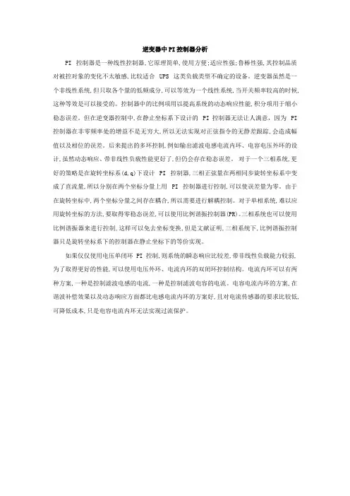
逆变器中PI控制器分析PI 控制器是一种线性控制器,它原理简单,使用方便;适应性强;鲁棒性强,其控制品质对被控对象的变化不太敏感,比较适合 UPS 这类负载类型不确定的设备。
逆变器虽然是一个非线性系统,但只取各个量的低频成分,可以等效为一个线性系统,当开关频率较高的时候,这种等效是可以接受的。
控制器中的比例项用以提高系统的动态响应性能,积分项用于缩小稳态误差。
但在逆变器控制中,在静止坐标系下设计的 PI控制器无法让人满意,因为 PI 控制器在非零频率处的增益不是无穷大,所以无法实现对正弦指令的无静差跟踪,会造成幅值以及相位的误差。
后来提出的多环控制,例如输出滤波电感电流内环、电容电压外环的设计,虽然动态响应、带非线性负载性能更好了,但仍会存在稳态误差。
对于一个三相系统,更好的策略是在旋转坐标系(d,q)下设计 PI 控制器,三相正弦量在两相同步旋转坐标系中变成了直流量,所以分别在两个坐标分量上用 PI 控制器进行控制,可以使误差量为零。
由于在旋转坐标中,两个坐标分量之间存在耦合,所以需要进行解耦控制。
对于单相系统,难以应用旋转坐标的方法,要取得零稳态误差,可以使用比例谐振控制器(PR)。
三相系统也可以使用比例谐振器来进行控制,这样可以免去坐标变换,但是文献证明,三相系统下,比例谐振控制器只是旋转坐标系下的控制器在静止坐标下的等价实现。
如果仅仅使用电压单闭环 PI 控制,则系统的瞬态响应比较差,带非线性负载能力较弱,为了取得更好的性能,可以使用电压外环、电流内环的双闭环控制结构。
电流内环可以有两种方案,一种是控制滤波电感的电流,一种是控制滤波电容的电流。
电容电流内环的方案,在谐波补偿效果以及动态响应方面都比电感电流内环的方案好,且对电流传感器的要求比较低,可降低成本,只是电容电流内环无法实现过流保护。
PI Controller v4.2 User GuideIntroduction (Ask a Question)Proportional Integral (PI) Controller is the widely used closed-loop controller for controlling a first order system. The basic functionality of a PI Controller is to make the feedback measurement track the reference input, which is done by controlling its output till the error between reference and feedback signals becomes zero.Summary (Ask a Question)Features (Ask a Question)PI Controller has the following key features:•Automatic anti-windup and initialization functions are includedImplementation of IP Core in Libero Design Suite (Ask a Question)IP core must be installed to the IP Catalog of the Libero® System-on-Chip (SoC) software. This is done automatically through the IP Catalog update function in the Libero SoC software, or the IP core can be manually downloadedfrom the catalog. Once the IP core is installed in the Libero SoC software IP Catalog, the core can be configured, generated, and instantiated within the SmartDesign tool for inclusion in the Libero project list.Device Utilization and Performance (Ask a Question)The following table lists the device utilization used for PI Controller.Table 1. PI Controller UtilizationImportant: 1.The data in this table is captured using typical synthesis and layout settings. CDR reference clocksource was set to Dedicated with other configurator values unchanged.2.Clock is constrained to 200 MHz while running the timing analysis to achieve the performancenumbers.Table of ContentsIntroduction (1)Summary (1)Features (1)Implementation of IP Core in Libero Design Suite (1)Device Utilization and Performance (1)1. Functional Description (4)1.1. Anti-Windup and Initialization (6)2. PI Controller Parameters and Interface Signals (7)2.1. Configuration of GUI Parameters (7)2.2. Input and Output Signals (7)3. Timing Diagrams (8)4. Testbench (9)4.1. Simulation (9)5. Revision History (12)Microchip FPGA Support (13)Microchip Information (13)The Microchip Website (13)Product Change Notification Service (13)Customer Support (13)Microchip Devices Code Protection Feature (13)Legal Notice (14)Trademarks (14)Quality Management System (15)Worldwide Sales and Service (16)1. Functional Description (Ask a Question)This section describes the implementation details of the PI Controller.The following figure shows the block diagram of PI Controller.Figure 1-1. System-Level Block Diagram of PI ControllerThe ref_input_i port connects to the reference input, while the act_input_i port connects to the actual input. Thekp_i and ki_i inputs represent the proportional and integral gains. ymax_i and ymin_i represent the minimum andmaximum outputs. The init_i input represents the initialization value (which is output if the PI Controller is disabled),and the pi_en_i input is used to enable the PI Controller operation. A pulse of one clock cycle width is used tostart the computation. The done_o output signal represents valid data on the output_y_o port. A single clock pulseappears at the done_o signal to represent the end of computation.The entire system is synchronized with the rising edge of clock and controlled by a finite state machine (FSM). The PI Controller block uses a multiply-accumulate-subtract (MAS) block to perform operations like multiplication, addition,and subtraction. There are two components that contribute to the output, the proportional term and the integral term as shown in the following figure. The proportional term is only dependent on the instantaneous value of the errorsignal whereas the integral term is dependent on the present and previous values of error.Figure 1-2. PI Controller in Continuous DomainPI Controller in continuous time domain can be expressed as:where,e(t) = reference(t) - feedback(t) is the error between Reference and feedbacky(t) = PI Controller outputTo implement the PI Controller in digital domain, it has to be discretized. The discretized form of PI Controller based on zero-order hold method is shown in the following figure.Figure 1-3. The Discretized Form of PI ControllerFigure 1-4. Equationwhere,P(n) = Proportional term outputI(n) = Integral term outputI(n-1) = Previous (buffered) value of Integral outputTs = Sampling time in discrete domain1.1 Anti-Windup and Initialization (Ask a Question)The PI Controller has maximum and minimum limits for its output so as to keep it within practical values. If a non-zero error signal persists for a long time, the Integral component of the controller keeps increasing and may reach avalue limited by its bit width. This phenomenon is called integrator windup and has to be avoided to have properdynamic response. The PI Controller IP has an automatic anti-windup function which limits integrator as soon as the PI Controller reaches saturation.In certain applications like motor control, it is important to initialize the PI Controller to a proper value before enabling it. Initializing the PI to a good value avoids jerky operation. The IP block has an enable input to enable or disable the PI Controller. When disabled, the output will be equal to the init input and when enabled, the output is PI computedvalue.PI Controller Parameters and Interface Signals 2. PI Controller Parameters and Interface Signals (Ask a Question)This section discusses the parameters in the PI Controller GUI configurator and I/O signals.2.1 Configuration of GUI Parameters (Ask a Question)The following table lists the description of the configuration parameters used in the hardware implementation of PIController. These are generic parameters that are customizable as per the requirement of the application.Table 2-1. Configuration Parameters2.2 Input and Output Signals (Ask a Question)The following table lists the input and output ports of PI Controller.Table 2-2. Inputs and Outputs of PI ControllerTiming Diagrams 3. Timing Diagrams (Ask a Question)This section discusses the PI Controller timing diagram.The following figure shows the timing diagram of PI Controller.Figure 3-1. PI Controller Timing Diagramsys_clk_istart_ikp_iki_iref_input_iact_input_iDone_ooutput_y_o4. Testbench (Ask a Question)A unified testbench is used to verify and test PI Controller called as user testbench. Testbench is provided to checkthe functionality of the PI Controller IP.4.1 Simulation (Ask a Question)The following steps describe how to simulate the core using the testbench:1.Open the Libero SoC application, click Catalog tab, expand Solutions-MotorControl, double click PIController, and then click OK. The documentation associated with the IP are listed under Documentation.Important: If you do not see the Catalog tab, navigate to View > Windows menu and clickCatalog to make it visible.Figure 4-1. PI Controller IP Core in Libero SoC Catalog2.On the Stimulus Hierarchy tab, select the testbench (pi_controller_tb.v), right click and then clickSimulate Pre-Synth Design > Open Interactively.Important: If you do not see the Stimulus Hierarchy tab, navigate to View > Windows menu andclick Stimulus Hierarchy to make it visible.Figure 4-2. Simulating Pre-Synthesis DesignModelSim opens with the testbench file, as shown in the following figure.Testbench Figure 4-3. ModelSim Simulation WindowImportant: If the simulation is interrupted due to the runtime limit specified in the .do file, use the run -all command to complete the simulation.Revision History 5. Revision History (Ask a Question)The revision history describes the changes that were implemented in the document. The changes are listed byrevision, starting with the most current publication.Table 5-1. Revision HistoryMicrochip FPGA Support (Ask a Question)Microchip FPGA products group backs its products with various support services, including Customer Service, Customer Technical Support Center, a website, and worldwide sales offices. Customers are suggested to visit Microchip online resources prior to contacting support as it is very likely that their queries have been already answered.Contact Technical Support Center through the website at /support. Mention the FPGA Device Part number, select appropriate case category, and upload design files while creating a technical support case.Contact Customer Service for non-technical product support, such as product pricing, product upgrades, update information, order status, and authorization.•From North America, call 800.262.1060•From the rest of the world, call 650.318.4460•Fax, from anywhere in the world, 650.318.8044Microchip Information (Ask a Question)The Microchip Website (Ask a Question)Microchip provides online support via our website at /. This website is used to make files and information easily available to customers. Some of the content available includes:•Product Support – Data sheets and errata, application notes and sample programs, design resources, user’s guides and hardware support documents, latest software releases and archived software•General Technical Support – Frequently Asked Questions (FAQs), technical support requests, online discussion groups, Microchip design partner program member listing•Business of Microchip – Product selector and ordering guides, latest Microchip press releases, listing of seminars and events, listings of Microchip sales offices, distributors and factory representativesProduct Change Notification Service (Ask a Question)Microchip’s product change notification service helps keep customers current on Microchip products. Subscribers will receive email notification whenever there are changes, updates, revisions or errata related to a specified product family or development tool of interest.To register, go to /pcn and follow the registration instructions.Customer Support (Ask a Question)Users of Microchip products can receive assistance through several channels:•Distributor or Representative•Local Sales Office•Embedded Solutions Engineer (ESE)•Technical SupportCustomers should contact their distributor, representative or ESE for support. Local sales offices are also available to help customers. A listing of sales offices and locations is included in this document.Technical support is available through the website at: /supportMicrochip Devices Code Protection Feature (Ask a Question)Note the following details of the code protection feature on Microchip products:•Microchip products meet the specifications contained in their particular Microchip Data Sheet.•Microchip believes that its family of products is secure when used in the intended manner, within operating specifications, and under normal conditions.•Microchip values and aggressively protects its intellectual property rights. Attempts to breach the code protection features of Microchip product is strictly prohibited and may violate the Digital Millennium Copyright Act.•Neither Microchip nor any other semiconductor manufacturer can guarantee the security of its code. Code protection does not mean that we are guaranteeing the product is “unbreakable”. Code protection is constantly evolving. Microchip is committed to continuously improving the code protection features of our products. Legal Notice (Ask a Question)This publication and the information herein may be used only with Microchip products, including to design, test,and integrate Microchip products with your application. Use of this information in any other manner violates these terms. Information regarding device applications is provided only for your convenience and may be supersededby updates. It is your responsibility to ensure that your application meets with your specifications. Contact yourlocal Microchip sales office for additional support or, obtain additional support at /en-us/support/ design-help/client-support-services.THIS INFORMATION IS PROVIDED BY MICROCHIP "AS IS". MICROCHIP MAKES NO REPRESENTATIONSOR WARRANTIES OF ANY KIND WHETHER EXPRESS OR IMPLIED, WRITTEN OR ORAL, STATUTORYOR OTHERWISE, RELATED TO THE INFORMATION INCLUDING BUT NOT LIMITED TO ANY IMPLIED WARRANTIES OF NON-INFRINGEMENT, MERCHANTABILITY, AND FITNESS FOR A PARTICULAR PURPOSE, OR WARRANTIES RELATED TO ITS CONDITION, QUALITY, OR PERFORMANCE.IN NO EVENT WILL MICROCHIP BE LIABLE FOR ANY INDIRECT, SPECIAL, PUNITIVE, INCIDENTAL, OR CONSEQUENTIAL LOSS, DAMAGE, COST, OR EXPENSE OF ANY KIND WHATSOEVER RELATED TO THE INFORMATION OR ITS USE, HOWEVER CAUSED, EVEN IF MICROCHIP HAS BEEN ADVISED OF THE POSSIBILITY OR THE DAMAGES ARE FORESEEABLE. TO THE FULLEST EXTENT ALLOWED BY LAW, MICROCHIP'S TOTAL LIABILITY ON ALL CLAIMS IN ANY WAY RELATED TO THE INFORMATION OR ITS USE WILL NOT EXCEED THE AMOUNT OF FEES, IF ANY, THAT YOU HAVE PAID DIRECTLY TO MICROCHIP FOR THE INFORMATION.Use of Microchip devices in life support and/or safety applications is entirely at the buyer's risk, and the buyer agrees to defend, indemnify and hold harmless Microchip from any and all damages, claims, suits, or expenses resulting from such use. No licenses are conveyed, implicitly or otherwise, under any Microchip intellectual property rights unless otherwise stated.Trademarks (Ask a Question)The Microchip name and logo, the Microchip logo, Adaptec, AVR, AVR logo, AVR Freaks, BesTime, BitCloud, CryptoMemory, CryptoRF, dsPIC, flexPWR, HELDO, IGLOO, JukeBlox, KeeLoq, Kleer, LANCheck, LinkMD, maXStylus, maXTouch, MediaLB, megaAVR, Microsemi, Microsemi logo, MOST, MOST logo, MPLAB, OptoLyzer, PIC, picoPower, PICSTART, PIC32 logo, PolarFire, Prochip Designer, QTouch, SAM-BA, SenGenuity, SpyNIC, SST, SST Logo, SuperFlash, Symmetricom, SyncServer, Tachyon, TimeSource, tinyAVR, UNI/O, Vectron, and XMEGA are registered trademarks of Microchip Technology Incorporated in the U.S.A. and other countries.AgileSwitch, APT, ClockWorks, The Embedded Control Solutions Company, EtherSynch, Flashtec, Hyper Speed Control, HyperLight Load, Libero, motorBench, mTouch, Powermite 3, Precision Edge, ProASIC, ProASIC Plus, ProASIC Plus logo, Quiet- Wire, SmartFusion, SyncWorld, Temux, TimeCesium, TimeHub, TimePictra, TimeProvider, TrueTime, and ZL are registered trademarks of Microchip Technology Incorporated in the U.S.A.Adjacent Key Suppression, AKS, Analog-for-the-Digital Age, Any Capacitor, AnyIn, AnyOut, Augmented Switching, BlueSky, BodyCom, Clockstudio, CodeGuard, CryptoAuthentication, CryptoAutomotive, CryptoCompanion, CryptoController, dsPICDEM, , Dynamic Average Matching, DAM, ECAN, Espresso T1S, EtherGREEN, GridTime, IdealBridge, In-Circuit Serial Programming, ICSP, INICnet, Intelligent Paralleling, IntelliMOS, Inter-Chip Connectivity, JitterBlocker, Knob-on-Display, KoD, maxCrypto, maxView, memBrain, Mindi, MiWi, MPASM, MPF, MPLAB Certified logo, MPLIB, MPLINK, MultiTRAK, NetDetach, Omniscient Code Generation, PICDEM, , PICkit, PICtail, PowerSmart, PureSilicon, QMatrix, REAL ICE, Ripple Blocker, RTAX, RTG4, SAM-ICE, Serial Quad I/O, simpleMAP, SimpliPHY, SmartBuffer, SmartHLS, SMART-I.S., storClad, SQI, SuperSwitcher, SuperSwitcher II, Switchtec, SynchroPHY, Total Endurance, Trusted Time, TSHARC, USBCheck, VariSense, VectorBlox, VeriPHY, ViewSpan, WiperLock, XpressConnect, and ZENA are trademarks of Microchip Technology Incorporated in the U.S.A. and other countries.SQTP is a service mark of Microchip Technology Incorporated in the U.S.A.The Adaptec logo, Frequency on Demand, Silicon Storage Technology, and Symmcom are registered trademarks of Microchip Technology Inc. in other countries.GestIC is a registered trademark of Microchip Technology Germany II GmbH & Co. KG, a subsidiary of Microchip Technology Inc., in other countries.All other trademarks mentioned herein are property of their respective companies.© 2023, Microchip Technology Incorporated and its subsidiaries. All Rights Reserved.ISBN: 978-1-6683-2116-4Quality Management System (Ask a Question)For information regarding Microchip’s Quality Management Systems, please visit /quality.Worldwide Sales and Service。

PI控制器要点编辑整理:尊敬的读者朋友们:这里是精品文档编辑中心,本文档内容是由我和我的同事精心编辑整理后发布的,发布之前我们对文中内容进行仔细校对,但是难免会有疏漏的地方,但是任然希望(PI控制器要点)的内容能够给您的工作和学习带来便利。
同时也真诚的希望收到您的建议和反馈,这将是我们进步的源泉,前进的动力。
本文可编辑可修改,如果觉得对您有帮助请收藏以便随时查阅,最后祝您生活愉快业绩进步,以下为PI控制器要点的全部内容。
4 心得体会通过本次课程设计,我加深了对自动控制原理课程知识的理解,其中一些在理论课上没搞懂的问题,在课程设计的过程中自己通过查阅大量的资料也搞懂了。
特别是系统稳定性分析,系统的校正以及比例环节,积分环节对系统稳定性以及系统动态性能和稳态性能的影响.在整个课程设计过程中大量借助MATLAB软件进行控制系统分析,加强了我对MATLAB语言的运用能力,让我掌握了许多MATLAB在控制科学的中的运用,诸如MATLAB中计算单位阶跃响应函数step(),计算任意输入响应函数lism(),特征根的求解roots,二维绘图函数plot(),根轨迹绘制函数rlocus()等等。
在书写课程设计说明书时运用了visio软件绘图,使用WORD软件编辑,使我掌握了许多关于办公软件的应用。
同时,在此次课程设计中,我感受到了查阅各类书籍的重要性,通过查阅图书馆的书籍可以开拓我们的视野,让我了解到自动控制原理在很多领域中的运用让我的思维不仅仅局限在课堂上,对同一个问题有多种分析思路、解决方法。
总之,这次课程设计不仅增加了我的知识积累,加强了我的独立思考能力和动手能力以及发现问题解决问题的能力为将来的学习和工作打下了很好的基础。
同时也让我认识到运用计算机分析的优越性与学习MATLAB工程软件的重要性。
课程设计的过程中我与同学、老师进行了深入的交流,通过交流我收获很大。
PI控制器要点5 参考文献[1] 胡寿松著。
pi调节器原理_pi调节器电路图_pi调节器参数作用PI调节器是一种线性控制器,它根据给定值与实际输出值构成控制偏差,将偏差的比例和积分通过线性组合构成控制量,对被控对象进行控制,下面就跟小编一起来了解下PI调节器的原理,电路以及其它pi调节器的知识吧。
什么是PI调节器PI调节器是一种线性控制器,它根据给定值与实际输出值构成控制偏差,将偏差的比例(P)和积分(I)通过线性组合构成控制量,对被控对象进行控制。
比例调节作用:按比例反应系统的偏差,系统一旦出现了偏差,比例调节立即产生调节作用用以减少偏差。
比例作用大,可以加快调节,减少误差,但是过大的比例,使系统的稳定性下降,甚至造成系统的不稳定。
积分调节作用:使系统消除稳态误差,提高无差度。
因为有误差,积分调节就进行,直至无差,积分调节停止,积分调节输出一常值。
积分作用的强弱取决于积分时间常数TI,TI越小,积分作用就越强。
反之TI大则积分作用弱,加入积分调节可使系统稳定性下降,动态响应变慢。
积分作用常与另两种调节规律结合,组成PI调节器或PID调节器。
PI调节器原理P是比例,I是积分,积分的作用是基于偏差量的,比例的作用是加快收敛速度的。
从自控原理上讲,PI调节不会带来右半平面的特征值,所以不会导致系统震荡,但是PI 调节是基于偏差的比例放大,所以偏差消失后,PI调节失去作用,导致PI调节不是无差调节系统,精度有限。
pi调节器作用(1)比例调节作用:按比例反应系统的偏差,系统一旦出现了偏差,比例调节立即产生调节作用用以减少偏差。
比例作用大,可以加快调节,减少误差,但是过大的比例,使系统的稳定性下降,甚至造成系统的不稳定。
(2)积分调节作用:使系统消除稳态误差,提高无差度。
因为有误差,积分调节就进行,直至无差,积分调节停止,积分调节输出一常值。
积分作用的强弱取决于积分时间常数TI,Ti越小,积分作用就越强。
反之Ti大则积分作用弱,加入积分调节可使系统稳定性。
pi控制器原理
pi控制器是一种常用的比例-积分控制器,其原理是通过调节控制器输出信号来控制被控对象的运行状态,以实现系统的稳定和精确的控制。
pi控制器的工作原理可以归纳为以下几个步骤:
1. 误差计算:pi控制器首先根据系统输出值与期望值之间的差异来计算误差。
这个差异被称为偏差,通常用e(t)表示。
偏差的大小和符号可以提供有关系统状态的信息。
2. 比例动作:pi控制器根据偏差的大小和符号,按比例输出一个控制量。
这个控制量与偏差成正比,比例增益Kp用于调节输出量的大小。
比例动作可以使系统更快地响应,但可能引起系统的超调和振荡。
3. 积分动作:pi控制器还具有积分动作,用于消除系统的稳态误差。
积分动作根据偏差与时间的积分值来计算,积分增益Ki用于调节积分作用的强度。
积分动作可以缓解系统稳态误差,但过大的积分增益可能导致系统不稳定。
4. 控制量调节:pi控制器将比例动作和积分动作的输出加权求和,得到最终的控制量。
这个控制量将传递给执行机构,通过调节执行机构的状态来改变被控对象的运行状态。
5. 反馈调节:pi控制器根据执行机构的状态和被控对象的输出值,不断调整控制量,以使系统的输出值逐渐接近期望值。
通
过不断反馈调节,系统可以实现稳定和精确的控制。
总结起来,pi控制器通过比例动作和积分动作来控制被控对象的状态,通过不断调整控制量来使系统输出逐渐接近期望值。
这种控制方式在工业自动化和控制系统中广泛应用,可以提高系统稳定性和控制精度。
PI控制器的设计
PID是一个经典的控制律,被广泛应用于各种控制系统中。
PID控制器可以用模拟电路来实现,也可以用数字算法来实现。
实际应用中,PI控制相对于PD 或PID控制用的更多一些。
下图为一个采用运放来实现的PI控制器电路:
U1A部分是比例为1的差分电路,此电路输入为反馈值和设定值输出为它们之间的偏差。
U1B部分是一个比例电路,比例系数为R2/R1 。
U1C部分是一个积分电路,积分系数为1/(R4 * C1) 。
U2A与U2B部分是一个加法电路,输出为控制值。
比例控制可以实现对偏差的快速响应,积分控制可以消除静差。
将比例与积分控制结合起来可以在消除静差的同时加快对偏差的响应。
采用上述电路设计了一个电流控制器,实现电流输出值对电流设定值的跟踪。
当仅采用积分控制时,波形如下(红色为设定值,橙色为输出值):
X轴单位为1ms
X轴单位为10us
当采用比例积分控制时,波形如下:
X轴单位为1ms
X轴单位为1ms
X轴单位为10us
由上可见,两种方法都可以消除静差,实现输出值对设定值的跟踪,不过相比于纯积分控制,比例积分控制的效果更好一些,超调量小,稳定时间短。
pi控制器原理PI控制器是一种常用的工业控制系统,在许多自动化控制系统中都有广泛的应用。
它是一种比例-积分控制器,通过对控制过程进行比例性和积分性的调节,使得系统能够更好地跟踪参考输入并保持稳定。
在本文中,我们将详细介绍PI控制器的原理、工作原理和应用。
1. PI控制器的原理PI控制器是由比例项(P项)和积分项(I项)组成的控制器。
其原理是根据控制系统的误差信号来调节控制输出,使得误差趋向于零,从而实现对控制过程的稳定控制。
PI控制器可以通过对误差信号进行线性加权来实现控制输出的调节,同时还可以通过对误差信号进行积分来消除系统的稳态误差,从而提高系统的稳定性和精度。
2. PI控制器的工作原理PI控制器的工作原理基于对系统的误差信号进行比例性和积分性的调节,以实现对系统的精确控制。
比例项(P项)主要根据误差信号的大小来确定控制输出的大小,而积分项(I项)则主要根据误差信号的时间积分来消除系统的稳态误差。
通过对比例项和积分项的合理调节,可以使得系统的响应速度更快、精度更高、稳定性更好。
3. PI控制器的应用PI控制器广泛应用于各种自动化控制系统中,例如温度控制、流量控制、压力控制、速度控制等。
在这些应用中,PI控制器可以通过对控制输出的调节,使得控制系统能够更好地跟踪参考输入并保持稳定。
另外,PI控制器还常用于工业生产中的各种自动化控制系统中,以实现对生产过程的精确控制和调节。
4. PI控制器的设计与调节设计和调节PI控制器是一个重要的工程问题,其目的是使得控制系统能够具有良好的性能指标,例如快速响应、稳定性和抗干扰能力。
通常情况下,可以通过对比例增益和积分时间常数进行调节来实现对PI控制器的优化设计。
比例增益决定了比例项的影响程度,而积分时间常数则决定了积分项的影响程度。
5. PI控制器的优缺点PI控制器作为一种常用的控制器,在工业控制系统中有着广泛的应用。
它具有响应速度快、稳定性好、抗干扰能力强等优点,因此在许多自动化控制系统中得到了广泛的应用。
PI 控制原理1.1 比例(P )控制比例控制是一种最简单的控制方式。
其控制器实质上是一个具有可调增益的放大器。
在信号变换过程中,P 控制器值改变信号的增益而不影响其相位。
在串联校正中,加大了控制器增益k ,可以提高系统的开环增益,减小的系统稳态误差,从而提高系统的控制精度。
控制器结构如图1:图11.2 比例-微分控制具有比例-微分控制规律的控制器称PI 控制器,其输出信号m(t)同时成比例的反应出输入信号e(t)及其积分,即:⎰+=tidt t e T k t ke t m 0)()()( (1)式(1)中,k 为可调比例系数;i T 为可调积分时间常数。
PI 控制器如图2所示。
图2在串联校正时,PI 控制器相当于在系统中增加了一个位于原点的开环极点,同时也增加了一个位于s 左半平面的开环零点。
位于原点的极点可以提高系统的型别,以消除或减小系统的稳态误差,改善系统的稳态性能;而增加的负实零点则用来减小系统的阻尼程度,缓和PI 控制器极点对系统稳定性及动态性能产生的不利影响。
只要积分时间常数i T足够大,PI 控制器对系统稳定性的不利影响可大为减弱,在控制工程中,PI 控制器主要用来改善控制系统的稳态性能。
2 P 和PI 控制参数设计2.1 初始条件:反馈系统方框图如图3所示。
K (s)D =1(比例P 控制律),sK K (s)D I+=2(比例积分PI 控制律),)6s )(1s (1s G 1+-+=s (s),)2s )(1s (1G 2++=(s)2.2 P 控制器设计2.2.1 比例系数k 的设定由题目给出的初始条件知,当G(s)=(s)1G ,未加入D(s )校正环节时,系统开环传递函数为:6)1)(s -s(s 1s (s)H(s)++=Gss s 651s 23-++= (2)又系统结构图可知系统为单位负反馈系统所以闭环传递函数为:)6)(1(11)6)(1(1)(+-+++-+=s s s s s s s s s φ155123+-++=s s s s (3)则系统的闭环特征方程为:D(s)=15523+-+s s s =0. 按劳斯判据可列出劳斯表如表1:Y图33s 1 -5 2s 511s 524-0s1表1由于劳斯表第一列符号不相同,所以系统不稳定,需要校正。
由任务要求得,当D(s)=D 1(s),G(s)=G 1(s)时,即加入P 控制器后,系统开环传递函数为:6)1)(s -s(s 1)k(s (s)H(s)++=G (4)其闭环传递函数为:k s k s s kks s +-+++=)6(5)(23φ (5)则系统的闭环特征方程为:D(s)=0)6(523=+-++k s k s s 按劳斯判据可列出劳斯表如表2:3s1 K-6 2s5k1s5304-k0sk 0表2要使系统稳定则必须满足劳斯表第一列全为正,即:{03040>->k k (6)所以系统稳定的条件为k>7.5.当单位阶跃信号输入时,系统稳态误差系数:)()(lim 0p s H s G K s →= (7)由式(4)得系统为1型系统,所以P K = ∞ 所以稳态误差:0111)(=∞+=+=∞P ss K R e(8)2.2.2 加入P 控制器后系统动态性能指标计算1)k 取不同值时的特征根由式(5)得系统稳定的条件为k>7.5。
下面对k 分别取7.5、15、30来讨论分析系统的动态性能指标。
当k=7.5时系统的闭环特征方程为:05.75.15)(23=+++=s s s s D (9)通过MATLAB 求得系统特征根,其程序如下: den=[1,5,1.5,7.5] roots(den)%求系统特征根 其运行结果如下: ans =-5.0000 -0.0000 + 1.2247i -0.0000 - 1.2247i即求得其特征根分别为:1s =-5,2s =j1.2247,31s =-j1.2247,。
其中有两个极点在虚轴上,系统临界稳定。
同理通过调用MATLAB 中的roots 函数即可分别求得k=15,k=20时的特征根。
K=15时,特征根为:1s =-3.6608,2s =-0.6696+j1.9103,31s =-0.6696-j1.9103。
K=30时,特征根为:1s =-1.6194,2s =-1.6903 -j 3.9583,31s =-1.6903 -j 3.9583。
2)k 取不同值时的单位阶跃响应由式(7)得当k=7.5时其闭环传递函数为:5.75.155.75.7)(231++++=s s s s s φ (10)当k=15时闭环传递函数为: 15951515)(232++++=s s s s s φ (11)当k=30时闭环传递函数为:302453030)(233++++=s s s s s φ (12)用MATLAB 求系统的单位阶跃响应,绘制出不同k 值时的单位阶跃响应曲线图,其程序如下:num1=[7.5,7.5]; den1=[1,5,1.5,7.5]; t1=0:0.1:15;y1=step(num1,den1,t1); num2=[15,15]; den2=[1,5,9,15]; y2=step(num2,den2,t1); num3=[30,30]; den3=[1,5,24,30]; y3=step(num3,den3,t1);plot(t1,y1,'r.',t1,y2,'--g',t1,y3,'b'),grid 程序运行后输出曲线图如图4:3)分别讨论不同k 值时的系统动态性能指标 如图2知当k=7.5时系统单位阶跃响应为无阻尼振荡。
当k=15时系统传递函数为式(11),下面借助LTIViewer 计算本控制系统单位阶跃响应时的性能指标。
MATLAB 程序如下: num=[15,15]; den=[1,5,9,15]; step(num,den); sys=tf(num,den); ltiview;程序运行后在弹出的LTIViewer 框中导入sys 函数,然后对绘制的曲线进行相应的设置后可以得到阶跃响应的各项指标点,效果图如图5所示:当光标移到对应点后,在浮出的文本框中可读出数据,列出如下: 上升时间:........................................s t r 373.0=峰值时间:.........................................st p 24.1=超调量:..............................................%7.89%p =σ图451015调节时间:..........................................st 65.6s =(0.05∆=)当k=30时系统传递函数为式(12),同理,通过MATLAB 绘出单位阶跃响应曲线图如图6所示。
上升时间:........................................s t r 24.0=峰值时间:.........................................st p 72.0=超调量:..............................................%2.68%p =σ调节时间:.......................................... s t 69.2s =(0.05∆=)图5Step ResponseTim e (sec)A m p l i t u d e01234567890.20.40.60.811.21.41.61.822.2.3加入P 控制器后系统动态性能分析:由式(2)得系统为含一个积分环节的三阶系统,在未加入P 控制器之前通过劳斯判据得系统处于不稳定状态。
当加入适当的P 控制器即比例环节后即可改善系统的稳定性。
同时根据图4以及不同k 值时的暂态系能指标可知通过增大控制器的开环增益可提高系统对阶跃信号的响应速度,降低系统的超调量,缩短系统的调节时间。
从而提高了系统的跟踪性能和稳定性。
Step ResponseTime (sec)A m p l i t u d e00.51 1.52 2.53 3.540.20.40.60.811.21.41.61.8图62.3 PI 控制器设计2.3.1 原系统性能分析当未加入PI 控制器时系统为二阶系统,其开环传递函数为: )2)(1(1)()(++=s s s H s G (13)系统闭环传递函数为:331)(2++=s s s φ (14)借助MATLAB 可绘制出系统单位阶跃响应曲线,具体程序如下:num=[1]; den=[1,3,3]; step(num,den); sys=tf(num,den); ltiview;程序运行后可得如下响应曲线图6:图6Step ResponseTime (sec)A m p l i t u d e2 2.5300.050.10.150.20.250.30.35由图6可看出该二阶系统处于过阻尼状态。
其稳态态误差系数: )()(lim 0p s H s G K s →= (15)=)2)(1(1lim0++→s s s =0.5 (16)所以其稳态误差为: pss k e +=∞11)(=0.667 (17)2.3.2 加入PI 控制器后系统性能指标初始条件条件:D(s)=))(11()(112sk k k s k k s D +=+= (18) 由式(18)知系统中串入了PI 控制器,比例系数为k ,积分时间常数1k k T i =。
当D(s)=D 2(s),G(s)=G 2(s)时,系统开环传递函数:)2)(1(1)()()(1+++=s s s k k s H s G (19)=)2)(1(1+++s s s kk s k(20)=ss s k ks 23231+++ (21)其闭环传递函数为:1231)2(3)(k s k s s k ks s +++++=φ (22)则闭环特征方程为:D(s)=0)2(3123=++++k s k s s 根据劳斯判据可列出劳斯表如表3: 3s 1 K+22s 31k1s 321+-k k 00s1k表3劳斯判据中要满足系统稳定则劳斯表第一列必需满足符号相同。
即:⎩⎨⎧>>+-00211k k k (23)所以系统稳定的条件为:201+<<k k 稳定时的允许区域如图7:当单位阶跃信号输入时,系统稳态误差系数:)()(lim 0p s H s G K s →= (24)=)2)(1(lim10+++→s s s kk s k s =∞(25)所以稳态误差:111)(=∞+=+=∞P ss K R e (26)2.3.3 k 和1k 取不同值对系统系能的影响下面在保持系统稳定且保证积分时间常数大于原系统的时间常数的情况即11>k k 的范围内分别取三组参数求取系统的闭环传递函数的特征根。