48V直流系统用户手册
- 格式:pdf
- 大小:10.54 MB
- 文档页数:67

锂电池充电站THC-20-48V/50A用户手册2016年12月1 概述该充电系统是我公司根据智能机器人用磷酸铁锂蓄电池组的充电技术要求,开发研制的一种智能充电装置。
该设备采用可编程序控制器作为主控单元,7英寸彩色液晶触摸屏作为人机交换平台;主电路采用高频开关电源电路,重量轻、体积小、效率高、稳压稳流精度高等特点。
整套设备操作方便、工作可靠、保护齐全、自动化程度高。
提供485通信接口及外控接点,给上位机适时交换数据及工作状态.1.1 额定技术参数1)交流输入电压: AC220V±10% 50Hz2)直流输出电压: DC 20-60V3)直流输出电流: DC 2-50A4)纹波:≤1%5)稳流精度:≤±1%6)稳压精度:≤±1%7)噪声:≤55dB(关闭前后门1米处)8)冷却方式:风冷9)外型尺寸高1200mm×宽600mm×厚500mm1.2 使用条件1.2.1海拔不超过2000m。
1.2.2 环境温度不低于-10℃,不高于+50℃。
1.2.3 空气最大相对湿度不超过90%(在相当于空气温度20±5℃时)1.2.4 运行地点无导电及爆炸尘埃,无腐蚀金属和破坏绝缘的气体或蒸汽,无强2电磁干扰。
1.2.5 空气流通较好的场所。
1.2.6 无剧烈振动和冲击,垂直倾斜度不超过5º。
2工作原理本设备主电路采用高频开关电源电路。
单相交流经整流调整后变为稳压稳流直流电并由控制中心发出命令给电池组充电。
高频开关电路以数字电路为基础,对系统输出电压、电流反馈信号先进行隔离放大并与给定信号比较后,将其误差信号进行模数转换成数字信号,输入到逻辑处理单元和其它控制信号一同进行逻辑控制、适时计算最终发出触发脉冲,从而保证其准确性、可靠性。
用户可通过触摸屏人机界面来指示设备轻松完成对蓄电池组的快速充电、均衡充电等任务。
3安装3.1安装装置到达安装地点后,小心开箱。

WENZHOU ROCKWILL ELECTRICCO.,LTD.DC Battery Bank-GZDW48V Controller System InstructionChapter 1 overview1.1 System configurationTHJK002G-48V monitor and control system is composed of two parts, the host controller THJK002G-3S-48V and data acquisition module, including charger, general data acquisition module, battery detection module, switch module and etc. Shown in table 1-1NOTE :(40-60)VDC power supply only, charger module exception. Bus and battery can not be grouped.1.2 Function introduction 1.2.1 THJK002G-3S-48V host unitBlue color 240*64 pixels LCDOptional English language, key operation, easy for parameter settings andinformation inquiry.RS485, RS232 interface optional, communication protocol CDT, MODBUS The real-time clock demonstrated, after power failure clock normal operation. May save 200 alarm logs, 48 work logs, after the power failure the informationdoes not lose.Battery charge management function and integrated system use1.2.2 ZHCL-2-48V unitDetects 1 3-phases AC voltage input.Detects 3 DC voltage, 2 current,1 battery temperature. Detects 24 D/I, 8 D/ONameModelFunction summaryHOST unitTHJK002G-3S-48VBlue color 240*64 pixels LCD, key option ChargerAC-DC/ DC-ACAC-DC applicable for charging systemDC-AC applicable for integrated system OptionalGeneral data acquisition module (choose either)ZHCL-2-48VDetest 1 AC voltageDetects 3 DC voltage, 2 current,1 temperature Detects 24 DI, 8 DO ZHCL-3-48V Detects 2 AC voltageDetects 6 DC voltage, 4 current,2 temperature Detects 32 DI, 8 DOBattery detector (optional)DCXJ-24-48VDetects 24 batteries the voltages, 1 temperatureSwitch moduleKGL-64-48V Detects 64 DI, 8 DO, max 4 pcs in one system1.2.3 ZHCL-3-48V unitDetects 2 3-phases AC voltage input.Detects 6 DC voltage, 4 current, 2 battery temperature.Detects 32 D/I, 8 D/O1.2.4 DCXJ-24-48V unitDetect 24 batteries, detection range, 0-16VDetect 1 battery temperature1.2.5 KGL-64-48V unitDetects 64 DI, 8 DO1.3 Typical solution1.3.1 Battery management systemApplicable for 48V battery and charging system and application useSystem configuration: 48V charger module, ZHCL-2-48V/ ZHCL-3-48V,KGL-64-48V, DCXJ-24-48VThe sample signal gathered by ZHCL module, the charging curve and optional module (KGL-64-48V、DCXJ-24-48V), see the following instruction.1.3.2 Integrated systemApplicable for system without battery charging management function,System configuration: 48V charger module, ZHCL-2-48V/ ZHCL-3-48V, KGL-64-48V Sample signal gathered by ZHCL module, optional(KGL-64-48V), see following instruction.1.4 Working environment●The work ambient temperature is not lower than - 5℃, is not higher than +40℃, theequipment saves ambient temperature permission for - 10℃~+60℃.●The work environment maximum relative humidity does not ≤90% (ambienttemperature is 25℃).●The movement place non-electric conduction dust, does not have the dipping and thedestruction insulation gas or the steam.●In door use only●Remark when place order if any special request.Chapter 2 THJK002G-3S-48V2.1Features2.1.1 Human interfaceBlue color 240*64 pixels LCD,Optional English menu, key operation, easy for settings and information inquiry2.1.2 Alarm informationAlarm text display, identify fault, max 50 current alarm texts.200 history fault records, do not lose once power failureAlarm indication, when alarm occurs, the LCD screen light, the buzzer sound.The alarm threshold is settable2.1.3 Battery managementWhen AC power supply input, charge the battery automatically according to preset parameters.Can work with battery detector DCXJ to detect the battery cell voltage, 24 cells, 1 group Manage charging process of one battery bankPerfect charing and discharging protection function2.1.4 Switch DI/DO16 DI, which the user can choose to define.Choose the switch type (alarm or state) and define the initial number8 DO, which the user can choose to define.2.1.5 PC end communicationInterface: RS232 or RS485.Protocol: MODBUS.Baud rate: 2400、4800 or 9600.Address range 01~99.2.1.6 Others48 working logs, record running information every half an hour. the information does not lose once power failure.If there is no key-press operation within 4 minute, then runs screen protection.The real-time clock demonstrated, after power failure clock normal operation.2.2 THJK002G-3S-48V interfaceFig 2-1 THJK002G-3S-48V front panelFig 2-2 THJK002G-3S-48V rear panelMark DescriptionESC Function key在不同的显示界面下有不同的定义,……ENT Function keyRUN When power on,the green LED light on.ALM When there is fault, the red LED flashRST Reset key.COM2 RTU RS485 interface.COM1 PC end communication RS232 1-RXD 2-TXD 3-GNDRS485 4-485A 5-485BPower supply Input power, range 40~60VDC, power ≤15WTable 2-1 THJK002G-3S-48V interface definition2.3 Operation instructionTwo working mode: integrated working mode, and battery management mode, which set by through the host monitor (parameter set--input type)2.3.1 integrated system operation instructionSetting method: parameter set→special set→input type set “DC IN” . Menu display structure, easy operation.2.3.1.1 basic operationEnter host interface after powered on. Shoe the system time, bus voltage, load currentand current fault.Time:Jan 1st, 2013 12:12:12Bus:voltage 53.2 V Load:0.0AFault: NonePress “ENT”, come to main interfaceInformationPara SettingSys ControlPassword Setting2.3.1.2 InformationShow the information inquiry menu. Press “▲” “▼” to move cursor and “enter”and get the following menu .1 AC info 5 History fault2 Charger info 6 Current fault3 Switches info4 Running logAC infoShow the system input voltageDC input 220.0VCharger infoShow the output voltage, current, working state (RUN/OFF)01#:Voltage 48.0V Current 10A RUN02#:Voltage 48.0V Current 10A RUN03#:Voltage 48.0V Current 10A RUN04#:Voltage 48.0V Current 10A RUNSwitches infoCheck switches info of ZHCL module, KGL moduleThe state of user defined switchesUndefined:Normal Undefined:NormalUndefined:Normal Undefined:Normal#2 inlet switch:Normal #1 inlet switch:Normal#2 Arrestor:Normal #1 Arrestor:NormalShow the alarm switch infoK001:Normal K002:Normal K003:NormalK004:Normal K005:NormalShow the state switch infoK010:Open K011:Open K012:OpenK013:Open K014:OpenRunning logShow the bus voltage, load current, fault info and record every half an hour. Max 48 records and delete the earliest record. The records are not lost once power failure.History faultThe type, starting time, ending time of history fault. Max 200 records and delete the earliest record if more. The records are not lost once power failure.Current faultShow the current fault type, starting time. Pop up new fault if any and audible and visual alarm.2.3.1.3 Parameter settings instructionThe parameter setting menu is as follows: move and press “ENT”to next parameter settings menu1 System settings 5 Alarm settings2 Charger settings3 Switch settings4 Other settingsSystem settingsSystem settings is for setting the system configuration, is the foundation of other settings.1 Charger quantity 012 KGL quantity 003 Sensor range 100ACharger quantity:the quantity of charger, range 0~15(0-14 if EMERSON protocol)KGL quantity: range 0~4Sensor range: range 50,100,150,200 (800)Charger module settings1 Rated voltage 48V2 Rated current 10A3 Over voltage alarm 58.0V4 Under voltage alarm 42.0V5 Output voltage 53.2VRated voltage:48V moduleRated current:the max output current, 10A,20A,25A,30A,50A,100A Over voltage alarm:range: under voltage alarm ~60VUnder voltage alarm:range:40V~over voltage alarmOutput voltage:output voltage of charging module, range:40V~60VKGL settings1 KGL output settings1)KGL output settingsD/O settings :K1~K8, options :comprehensive fault, charger fault, DC inputfault, AC fault, battery fault, bus fault, feeder fault, battery float charge, battery boost charge, battery discharge, group #1 float charge, group #1 boost charge, group #1 discharge, group #2 boost charge, group #2 discharge, charger 1 fault, charger 2 fault, charger 3 fault, charger 4 fault, battery fuse, system OK, B1 primary power down, B1 secondary power down, B2 primary power down, B2 secondary power down. 2) D/I settingsTake ZHCL D/I for example, the menu is as followsSpecial switch quantity: max 16 user defined switches, normally open and willalarm.Alarm switch quantity :24 (ZHCL-2-48V), 32 (ZHCL-3-48V), KGL-64, normallyopen, display mode: alarm.Alarm initial number: the number of first alarm switch, max 500.State switch quantity: 24 (ZHCL-2-48V), 32 (ZHCL-3-48V), KGL-64, normally01 ZHCL special switch quantity 1602 ZHCL alarm switch quantity 5 03 ZHCL alarm initial number 001 04 ZHCL state switch quantity 3 05 ZHCL state initial number 01006 ZHCL other 01 No definition 07 ZHCL other 02 No definition08 ZHCL other 03 No definition 09 ZHCL other 04 No definition1 Output switch K1 comprehensive fault2 Output switch K2 Charger fault3 Output switchK3 Insulation fault4 Output switchK4 AC faultclose, display mode: open/close, no alarmState initial number: the number of first state switch, max 500.Special switch options: AC switch, DC switch, DC fuse, battery switch, battery fuse, discharge switch, inverter switch, feeder switch, 1# arrestor, 2# arrestor, inverter, DC converter, battery fault, battery fuse, 1# AC switch, 2# AC switch, 3# AC switch, 4# AC switch, 5# AC switch, 6# AC switch, 7# AC switch, 8# AC switch, 9# AC switch, 10# AC switch, 11# AC switch, 12# AC switch, 13# AC switch , 14# AC switch, 1# DC switch, 2# DC switch, 1# DC fuse , 2# DC fuse, 1# battery fuse, 2# battery fuse, 1# battery switch, 2# battery switch, 1# discharge switch, 2# discharge switch, 3# AC switch, 4# AC switch, 1# bus switch, 2# bus switch, charger input switch, 1# charger input switch, 2# charger input switch, 3# charger input switch, 4# charger input switch, charger output switch, 1# charger output switch, 2# charger output switch, 3# charger output switch, 4# charger output switch, 1# distribution panel switch, 2# distribution panel switch, 3# distribution panel switch, 4# distribution panel switch, 1 # feeder panel switch, 2 # feeder panel switch, 3 # feeder panel switch, 4 # feeder panel switch, #1 inlet switch, #2 inlet switch, interconnection switch, UPS input switch, UPS output switch, 5# charger in switch, 6# charger in switch, 5# charger out switch, 6# charger out switch, comprehensive fault, charger fault, input voltage fault, no definition.Other settings1 Communication settings2 Time settings3 Other settingsGet following menu after enter special password1 Communication settings 5 Version2 Time settings3 Other settings4 Special settings1)CommunicationSet communication add :001~099 Set communication baud rate :2400、4800、9600Communication protocol :Modbus Interface: RS4852) Time settings Set system time 3) Other settingsContrast control : Adjust screen display,10-60 Delete history fault :Delete history fault Delete running log :Delete running logDelete discharge record :delete discharge capacity, discharge time record 4) Special settingsMeasure calibration: ZHCL online calibration Special settings1 Communication add. 12 Baud rate 96003 Communication protocol ModBus4 Interface RS485 1 Measure calibration 2 Special settings5 Input type Three6 Input numbers 17 Charger protocol TH 1 Factory settings NO 2 Language English 3 ZHCL ZHCL-2-48V 4 Charger type LED1、Contrast control 452、Delete history fault No3、Delete running log No4、Delete discharge recordNoInput type :single phase, three phases, DC. The system is batterymanagement system when the input AC (single/three), and is integratedsystem if input DCInput numbers :1 if single and DC input, 2 if three phases input and workwithZHCL-3-48VCharger protocol :TH/AMS1/AMS2Bus section, battery group, charger group: only 1 Alarm settingsinput over voltage :range: under voltage~480V Input under voltage :range: 80V~input over voltage Bus over voltage :range: bus under voltage~60.0V Bus under voltage :range: 40.0 V ~bus over voltage2.3.1.4 system controlCharger control :charger on/off (disable this function temporarily )2.3.1.5 password settingsDefault factory password is 0000, the user can set new password2.3.2 Charging management system operation instructionSetting method :set the “input type ” under “parameter settings ” to “Three” or “Single”. Menu display and easy operation.Layer stepping structure, easy operation. It comes the main Interface after power on and9 Battery groups 1 TH10 Charger groups 1 1 input over voltage286V 2 input under voltage 198V 3 bus over voltage 58.0V4 bus under voltage 48.0V1、Charger control power ondisplay the system time, battery information, control busbar information, and current state.Press“ENT”button, enter main menu2.3.2.2 Info inquiryShown as belo w: the info inquiry menu, move the cursor and select by press “ENT ” , then enter the selected menuAC info inquiryDisplay the AC input voltageTwo AC input, the AC data are as follows:One AC input, the AC data are as follows :Charger infoSee 2.3.1.2, the state of charger: float/boost Switch infoSee 2.3.1.2 Running logDisplay the battery voltage, current, bus voltage, current, float/boost status and faults during the system operation process. Automatic record every half an hour. Max 48 history log record and the previous records will be deleted. The records will not loss if powerAC input 220.0VTime : October 19, 2012 14:58:41 Batt : Volt 53.2V Current : 0.0A Corl bus : Volt 53.2V Load : 0.0A State : Float charge Fault : No1:Info inquiry2:Parameter set3:System control4:Password set1:AC info 5:history fault 2:Charger info 6:current fault 3:Switch info 7:battery info 4:Running logAC I Switch off AC II Switch off AB : 380.0V AB : 380.0V AC : 380.0V AC : 380.0V BC : 380.0V BC : 380.0Vfailure.History faultSee 2.3.1.2Current faultSee 2.3.1.2Battery infoDisplay battery pack voltage, current, temperature, single cell voltage if there is DCXJ module in the system.2.3.2.3 Parameter set instructionInclude:System set menu, move the cursor and select by press “ENT” to enter the selected menu1、System set 5、alarm set2、Charger set 6、DXCJ3、switch set 7、battery management4、other setSystem settingsSystem settings is for setting the system configuration, is the foundation of other settings.1 Charger quantity 012 KGL quantity 003 Sensor range 100A4 DXCJ module quantity 00Charger quantity:the quantity of charger, range 0~15(0-14 if EMERSON protocol)KGL quantity: range 0~4Sensor range: range 50,100,150,200 (800)DXCJ quantity: 0-1Charger module settings1 Rated voltage 48V2 Rated current 10A3 Over voltage alarm 58.0V4 Under voltage alarm 42.0V5 float charge voltage 53.2VRated voltage:48V moduleRated current:the max output current, 10A,20A,25A,30A,50A,100A Over voltage alarm:range: under voltage alarm ~60VUnder voltage alarm:range:40V~over voltage alarmFloat charge voltage: range: under voltage threshold-boost charge voltage Boost charge voltage: range: float charge voltage-over voltage thresholdDI/DO settingSee 2.3.1.3Other settingsSee 2.3.1.3Alarm settings1 input over voltage 450V2 input under voltage 304V3 bus over voltage 58.0V4 bus under voltage 48.0V5 Battery over voltage 58.0V6 Battery under voltage 48.0V7 Battery over current 040A8 Backlash 05V9、LVDS primary power down 46.0V10、LVDS secondary power down 43.4Vinput over voltage:range: under voltage~480VInput under voltage:range: 80V~input over voltageBus over voltage:range: bus under voltage~60.0VBus under voltage:range: 40.0 V ~bus over voltageBattery over voltage:battery under voltage~60.0V。

RTN (+) RTN (+)(-)(-)Default Reset ButtonMake changes shown. Point your browser at 192.168.0.100 and log in.The IP address of the DST-8-RB needs to match the “class C”To access the home page, first enter the IP address in web browser URL field, then log in. User admin has access to all features. Other users have limited access to relays as assigned by the administrator. When configuring the DST-8-RB for the first time, use the default admin username and 1234 password.The home page contains 13 external hyperlinks. The first nine are fixed internal links: The four links in the lower left corner of the screen are user-programmable.1) Relay Control - Switching Relays On and OffThe relay control page lets you control any relay (except the always-on pair). A master setting also allows users (with security access) to switch all relays on or off.To switch an relay on or off, simply click to the right of the relay name or number. Switching is immediate.Use the keypad for local control: Select a relay using the arrow keys, then press on, off, or cycle. Press ON or OFF for 5 seconds to lock or unlock a relay. Locking prevents web access.You may also Cycle a device which is connected to the DST-8-RB. This feature is useful for rebooting Ethernet devices which may interrupt the web link to the controller.We connect the router to relay 1, and add the external IP here, leaving all timing values at defaults. We first add the IP here:11. Specifications。
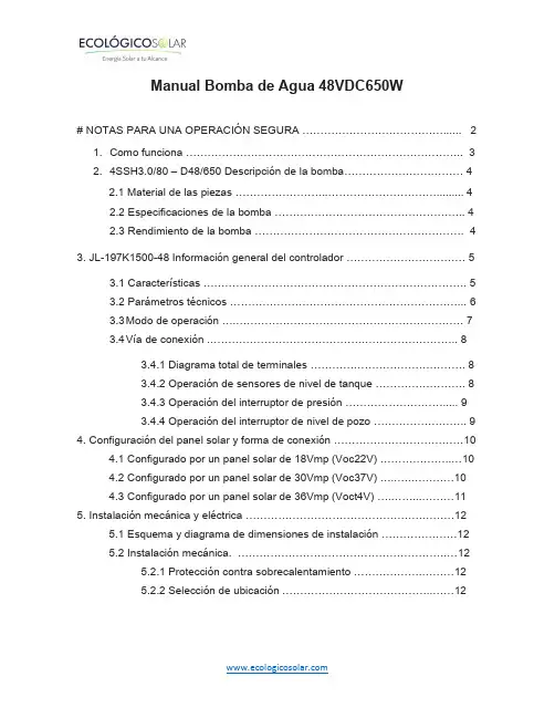
Manual Bomba de Agua 48VDC650W# NOTAS PARA UNA OPERACIÓN SEGURA (2)1. Como funciona (3)2. 4SSH3.0/80 – D48/650 Descripción de la bomba (4)2.1 Material de las piezas (4)2.2 Especificaciones de la bomba (4)2.3 Rendimiento de la bomba (4)3. JL-197K1500-48 Información general del controlador (5)3.1 Características (5)3.2 Parámetros técnicos (6)3.3 Modo de operación (7)3.4 Vía de conexión (8)3.4.1 Diagrama total de terminales (8)3.4.2 Operación de sensores de nivel de tanque (8)3.4.3 Operación del interruptor de presión (9)3.4.4 Operación del interruptor de nivel de pozo (9)4. Configuración del panel solar y forma de conexión (10)4.1 Configurado por un panel solar de 18Vmp (Voc22V) (10)4.2 Configurado por un panel solar de 30Vmp (Voc37V) (10)4.3 Configurado por un panel solar de 36Vmp (Voct4V) (11)5. Instalación mecánica y eléctrica (12)5.1 Esquema y diagrama de dimensiones de instalación (12)5.2 Instalación mecánica. (12)5.2.1 Protección contra sobrecalentamiento (12)5.2.2 Selección de ubicación (12)1. Cómo funcionaEl sistema de bombeo solar sirve para proporcionar agua en aplicaciones remotas donde la energía de la red eléctrica no es confiable o no está disponible. El controlador de la bomba solar BLDC puede utilizar directamente la energía de DC del conjunto de elementos fotovoltaicos y controlar las bombas de DC sin escobillas. En días soleados, el sistema de bombeo puede bombear agua continuamente. No hay necesidad de baterías u otros dispositivos de almacenamiento de energía. Se recomienda bombear agua a un depósito para su almacenamiento.Se puede instalar un interruptor de flotador en la torre de agua para controlar el funcionamiento de la bomba. E instale una sonda de bajo nivel en el pozo para detectar el agua del pozo y que la bomba se detenga cuando no haya agua. La Figura 1 muestra un diagrama típico del sistema de bombeo solar, que incluye partes y componentes principales.Consiste en:Matriz PVControlador de bomba de energía solarBomba sumergible de energía solarInterruptores de nivel de fuente de aguaInterruptores de nivel de tanque2. 4SSH3.0/80 – D48/650 Descripción de la bomba 2.1 Material de las piezas2.2 Especificaciones de la bomba2.3 Rendimiento de la bomba3. JL-197K1500-48 Información general del controlador3.1 CaracterísticasEl controlador de bomba solar JL-197K1500-48 está diseñado con el alto estándar de confiabilidad que se espera de los productos. El controlador intenta impulsar la bomba y el motor para suministrar agua incluso en condiciones adversas, reduciendo la salida según sea necesario para proteger los componentes del sistema de daños y solo apagándose en casos extremos. La operación completa se restaura automáticamente cada vez que disminuyen las condiciones anormales.InspecciónAntes de comenzar, inspeccione la unidad controladora de la bomba solar JL-197K1500-48. Verifique que el número de pieza esté conectado y que no haya ocurrido ningún daño durante el tránsito.NOTA: El controlador de bomba solar JL-197K1500-48 es el componente del sistema de bombeo solar que tiene otros dos componentes, la matriz PV y la bomba de DC sin escobillas.Características de protecciónLa monitorización electrónica le da al controlador la capacidad de monitorear el sistema y apagarse automáticamente en caso de:Condiciones de pozo seco - con interruptor de bajo nivelBomba enlazada - con par de inversión automáticaSobretensión de alto voltajeBajo voltaje de entradaCircuito de moto abiertoCortocircuitoSobrecalentamientoNOTA: Este controlador proporciona protección contra sobrecarga del motor al evitar que la corriente del motor exceda la corriente nominal y al limitar el ciclo de trabajo en caso de bajo nivel de agua. Este controlador no proporciona detección de temperatura excesiva del motor.Diagnósticos del sistemaEl controlador de bomba solar JL-197K1500-48 monitorea continuamente el rendimiento del sistema y detecta una variedad de condiciones anormales. En muchos casos, el controlador compensará según sea necesario para mantener la operación continua del sistema; Sin embargo, si existe un alto riesgo de daños en el equipo, el controlador protegerá el sistema de la condición de falla. Si es posible, el controlador intentará reiniciarse cuando la condición de falla disminuya.Arranque suave del motorNormalmente, cuando hay una demanda de agua y energía disponible, el controlador de bomba solar JL-197K1500-48 estará en funcionamiento. Cada vez que el controlador de la bomba solar JL-197K1500-48 detecta una necesidad de agua, el controlador siempre "aumenta" la velocidad del motor mientras aumenta gradualmente el voltaje del motor, lo que resulta en un motor más frío y una corriente de arranque más baja en comparación con los sistemas de agua convencionales. Esto no dañará el motor debido a la función de arranque suave del controlador.Exceso de temperaturaEl controlador de bomba solar JL-197K1500-48 está diseñado para funcionar a plena potencia desde una matriz solar en temperaturas ambiente de hasta 45 C. En condiciones de temperatura superiores a 45 ° C, el controlador reducirá la potencia de salida en un intento de evitar apagar. La salida completa de la bomba se restablece cuando la temperatura del controlador se enfría a un nivel seguro. Interruptor de control de nivelEl controlador de bomba solar JL-197K1500-48 puede acceder a dos interruptores de nivel de agua (sensor de nivel de pozo y un sensor de nivel) para detectar de forma remota y controlar la bomba automáticamente. El interruptor de nivel para el controlador de bomba JL-197K1500-48 es opcional, no obligatorio.EmpujeControl de velocidad Presione para correr detenerDescripción ligera y causa3.4 Forma de conexiónvoltajeVelocidadEncender / Apagar3.4.1 Diagrama total de terminalesu v w Conectar con la bomba U V W cablesPV + PV – Conectar con panel fotovoltaico PV + PV-WL & COM Conectar con sensor de nivel de agua de pozoTL & TH & COM Conectar con sensor de palanca de agua del tanque3.4.2 Operación del sensor de nivel de panque3.4.3Operación del interruptor de presión3.4.4La operación del nivel de pozo4.Panel solar configurar y forma de conexión 4.1configurado por un panel solar de 18 Vmp (VOC 22V)4.2Configurado por 30Vmp (Voc 37V) Panel solar4.3 configurado por 36Vmp (Voc44V) Panel solar5.Instalación mecánica y eléctrica5.1 Esquema y diagrama de dimensiones de instalación5.2 Instalación mecánica5.2.1 Protección contra sobrecalentamientoSi está en el exterior, el controlador debe instalarse en un lugar bien ventilado y evitar la luz solardirecta y la lluvia. La mejor ubicación de instalación está debajo del conjunto solar, lo que puede evitarel sobrecalentamiento del equipo y la degradación del rendimiento. La temperatura extremadamente alta puede hacer que el controlador deje de protegerse.Sugeriremos utilizar una caja eléctrica con interruptor.5.2.2 Selección de ubicaciónEl controlador de la bomba solar de la serie JL-197K está diseñado para funcionar a temperaturasambiente máximas de hasta 60 ° C. Para evitar el sobrecalentamiento causado por la falla, serecomienda instalar el controlador en una posición oscura.El controlador de la bomba solar de la serie JL-197K debe instalarse en una caja de control que tenga unrecinto cerrado para evitar la luz solar directa, lluvia, polvo, humedad, animales, plantas, etc. La caja decontrol debe tener una placa de glándula inferior para instalar el cable de alambre o conducto. Paradecidir el tamaño de la caja de control, consulte la siguiente Figura 4.。
+- +-+-光电池 蓄电池 负载+- +-+- 光电池 蓄电池 负载■ 常见故障现象及处理方法:在出现下列现象时,请按照下述方法进行检查:注:本公司保留变动的权利,恕不通知。
■系统说明:本控制器专为太阳能直流供电系统、太阳能直流路灯系统设计,并使用了专用电脑芯片的智能化控制器。
采用一键式轻触开关,完成所有操作及设置。
具有短路、过载、独特的防反接保护,充满、过放自动关断、恢复等全功能保护措施,详细的充电指示、蓄电池状态、负载及各种故障指示。
本控制器通过电脑芯片对蓄电池的端电压、放电电流、环境温度等涉及蓄电池容量的参数进行采样,通过专用控制模型计算,实现符合蓄电池特性的放电率、温度补偿修正的高效、高准确率控制,并采了用高效PWM蓄电池的充电模式,保证蓄电池工作在最佳的状态,大大延长蓄电池的使用寿命。
具有多种工作模式、输出模式选择,满足用户各种需要。
■安装及使用:1.控制器的固定要牢靠,安装孔如图示:外形尺寸:203×123 (mm)安装孔尺寸:193 ×83 (mm)2.导线的准备:建议使用多股铜芯绝缘导线。
先确定导线长度,在保证安装位置的情况下,尽可能减少连线长度,以减少电损耗。
按照不大于4A/mm2的电流密度选择铜导线截面积,将控制器一侧的接线头剥去5mm的绝缘。
3.先连接控制器上蓄电池的接线端子,再将另外的端头连至蓄电池上,注意+,—极,不要反接。
如果连接正确,指示灯(2)应亮,可按按键来检查。
否则,需检查连接对否。
如发生反接,不会烧保险及损坏控制器任何部件。
保险丝只作为控制器本身内部电路损坏短路的最终保护。
4.连接光电池导线,先连接控制器上光电池的接线端子,再将另外的端头连至光电池上,注意+,—极,不要反接,如果有阳光,充电指示灯应亮。
否则,需检查连接对否。
5、负载连接,将负载的连线接入控制器上的负载输出端,注意+,—极,不要反接,以免烧坏用电器。
6、接光电池和负载的导线应该如图所示在端子下方留一个弧度防止雨水沿导线进入控制器。

User Manual Wind and Solar Hybrid Charge ControllerHCON Series1KW / 2KW 48VDCDear Customer,Thank you very much for choosing our product. This manual contains important information about the installation and operation of your wind and solar charge controller. Please read this manual carefully before installing and using the product.Any work should follow the required safety standards and applicable regulations. The product should be handled and installed by professionals or appropriately qualified persons. Suitable precautions and safety measures should be taken in all cases.1. Product overviewThis controller has been designed to charge 48V lead acid battery banks from wind turbines and solar panels. The controller can be used with either a wind turbine alone, or a solar array alone, or wind + solar combined charging one battery bank at the same time.Warning! The “nominal” voltage of your wind turbine and the solar array should match the battery bank voltage 48V. This controller is only suitable for:- 48V wind turbines (3-phase AC 50-65V output)- 48V solar arrays (maximum power voltage 64-80V, open circuit voltage 80-100V).The controller comes packaged with a separate dump load unit which is required for unloading and protecting the battery whenit is fully charged.Features●Intelligent and powerful technology ensures a high level ofproduct reliability●Simple structure with a modular design guarantees astable performance●PWM charging mode for optimal charge acceptance by thebattery bank● A range of protection functions (overcharging, overvoltage,reverse polarity, load short circuit, lightning, current limiting, automatic brake etc)●Inbuilt temperature sensor for temperature compensationof charging●Small current charging mode for a low battery (gentlecharging of a very low battery with only part of the available current)Optional FeaturesThe controller comes with an in-built RS485 communication port which can accept connection of various devices, such as a remote meter display, control panel, GPRS communication module etc. These devices are optional and need to be purchased / configured separately from the controller, using the appropriate RS485 to USB / RS485 to 232 converting cables.2. First use and operating procedures1) Use insulated copper or tinned copper cables of theappropriate cross-section (but in any case not smaller than6 mm2) to connect system components.2) Connect the dump load to the DUMP LOAD terminals ofthe controller.3) Connect the battery to the BATTERY terminals on thecontroller. Although the controller has reverse polarityprotection, make sure the positive and negative cablesare connected to the correct “+” and “-” terminals.4) Attach the wind turbine output cables to the WIND INPUTterminal on the unit. Please make sure the wind turbine blades are not rotating or are moving at a very slowspeed during this step of the installation.5) Finally, connect the solar panel(s)to the positive andnegative SOLAR INPUT terminals on the controller.Please keep the solar panel(s) covered during this process.Wiring diagram6) The controller comes with an On / Off switch on the frontpanel. This switch is designed for customers looking to disable battery charging and divert all energy to the dump load (e.g. when away from the system for a long period of time). When the controller is in normal operation of the battery charging, this switch should stay in the “On”position.Turning it into the “Off” position disables battery charging and activates the dump load.7) If you need to disconnect the wind turbine for a significantperiod of time, please note that for most wind turbines it is not recommended that the 3 wind turbine AC output wires remain open circuit. Typically the best method is to short all three wires and isolate them from other objects. Consult your wind turbine manufacturer or supplier for detailed guidance on this question before making a decision.3. Display informationPressing “READ” on the controller will show the battery voltage, solar charge current, wind turbine charge current and wind turbine revolutions per minute (RPM).Name DescriptionLight IndicatorVShows battery voltageI1Shows PV currentI2Shows wind turbine current r/minShows wind turbine RPMUnShows controller is unloading CHShows controller is chargingNote: Indicates that the light is illuminated.4. Fault indicationThe following fault codes might appear on the controller display.5. Mechanical dimensions6. Data and Specifications。
Installation and Operations ManualSEI DC-UPS48Vdc SERIESSEI Incorporated5115 Pegasus Court, Suite QFrederick, MD 21704Phone 301-694-9601Fax 301-694-9608Email *****************Web TABLE OF CONTENTSTable of Contents (1)Description (2)Technical Specifications (3)Environmental Specifications (4)Safety Information (4)Installation Instructions (5)Startup and Checkout (7)System Shutdown (7)Theory of Operation (8)Remote Alarm Option (10)Power Management Package Option (11)Repair and Maintenance (11)Storage (11)DESCRIPTIONThe SEI DC-UPS series is a compact unit designed to service a wide range of customer equipment requiring battery-backed 48 VDC power. The DC-UPS series comes equipped with up to 600 Watts of rectifier power. The output power distribution is provided on the right side of the unit. Commercial power is applied to the left side of the unit. The SEI DC-UPS can be mounted on a wall or on a 19-inch rack. Optionally, SNMP communications via the Power Management Package (PMP) is available. Two Alarm Contacts are also available.The DC-UPS series offers three different models with a range of output current:∙ SEI 125/48-P – 2.25 Amps (125 Watts)∙ SEI 300/48-P – 5.5 Amps (300 Watts)∙ SEI 600/48-P – 11.0 Amps (600 Watts)Output power distribution is provided via a pair of fused 10/32 binding posts. The SEI 125/48-P contains a single output port. The SEI 300/48-P and SEI600/48-P each contain two individually-fused output ports. Customer-specified output modules are available. The DC-UPS comes equipped with field replaceable, non-spillable sealed lead acid battery packs. Circuitry within the DC-UPS monitors and periodically tests the condition of the batteries and displays the results via external LEDs as well as over the network when equipped with the optional Power Management Package. The DC-UPS also utilizes a Low Voltage Disconnect (LVD) circuit that prevents damage to the Battery Packs during an extended AC outage.TECHNICAL SPECIFICATIONSSEI 125/48-PElectrical SpecificationsInputVoltage 100-264 VACFrequency 50-60 HzCurrent 1.5 Amps Typical(115 Vac input, 125 W output)5.0 Amps MaxOutputVoltage 42-55.2VDCCurrent 3 amps MaxOutput Fuse ATO 7.5A Littlefuse 166.7000.4752 or Equivalent Mechanical DimensionsWidth 19.0 InchesDepth 5.0 InchesHeight 7.0 InchesWeight 20 lbsBattery PackCapacity 2.5AhrFuse 3AG 6A Littlefuse 0326006 or EquivalentSEI 300/48-PElectrical SpecificationsInputVoltage 100-264 VACFrequency 50-60 HzCurrent 3.3 Amps Typical(115 Vac input, 300 W output)5.0 Amps MaxOutputVoltage 42-55.2VDCCurrent 7.1 amps MaxOutput Fuse ATO 7.5A Littlefuse 166.7000.4752 or Equivalent Mechanical DimensionsWidth 10.0 InchesDepth 5.0 InchesHeight 14.0 InchesWeight 32 lbsBattery PackCapacity 9.0AhrFuse 3AG 10A Littlefuse 0326006 or EquivalentSEI 600/48-PElectrical SpecificationsInputVoltage 100-264 VACFrequency 50-60 HzCurrent 6.5 Amps Typical(115 Vac input, 600W output)8.5 Amps MaxOutputVoltage 42-55.2 VDCCurrent 15 amps MaxOutput Fuse ATO 15A Littlefuse 142.6185.5152 or Equivalent Mechanical DimensionsWidth 19.0 InchesDepth 5.0 InchesHeight 10.0 InchesWeight 32 lbsBattery PackCapacity 9.0AhrFuse 3AG 15A Littlefuse 0326015 or EquivalentENVIRONMENTAL SPECIFICATIONS TemperatureOperating -20︒ C to +50︒ CStorage -20︒ C to +50︒ CHumidity 0-95% non-condensingThermal LoadSEI 125/48-P 70 BTU/hr maxSEI 300/48-P 140 BTU/hr maxSEI 600/48-P 270 BTU/hr maxSAFETY INFORMATIONAlways ensure that the person assigned to the job can perform the job safely.Always lift all equipment properly.Always disconnect commercial power and remove the battery fuse before working on the unit.Always replace the batteries with batteries of the same type and style.DO NOT work on this equipment during an electrical storm.DO NOT work in locations where there is condensing moisture or standing water.Service to the DC-UPS should be performed by a qualified technician.INSTALLATION INSTRUCTIONSGENERALThe installation section of this manual will provide all the necessary information for room requirements, proper inspection, and installation.InspectionThe equipment has been fully tested and inspected prior to shipment. Although the unit has been packed in accordance with good commercial practices, it does not preclude damage in transit.The following actions should be taken on receipt of the equipment:▪ Visually inspect the shipping container for damage. If damaged, request that the carrier inspect the shipment.▪ Unpack the inner container from the shipping container and remove the unit from the packaging. Inspect the unit for visible damage.If a claim for damages is to be made, it should be filed promptly with the transportation company. In addition, notify SEI within two days of delivery. SEI will advise the customer of any further procedures that may be required, including an RMA number in the event that the unit has to be returned to the factory for repair.Make sure the following items are included inside the package:▪ One SEI DC-UPS Unit.▪ One AC Power Cord.▪ One Plastic Terminal Cover with hardware▪ One Installation and Operations Manual.Room RequirementsElectrical Requirements∙ Each unit requires a separate NEMA 5-15R receptacle protected by a 15 Amp circuit breaker.∙ A standard 7 foot 6 inch power cord with a molded NEMA 5-15 plug is supplied with each unit.Mounting Instructions∙ The SEI DC-UPS weighs between 20 and 32 lbs, depending upon the model.∙ The SEI DC-UPS is designed to mount to a rack or wall without further requirements for additional mounting kits. For wall mounting, a user supplied 3/4-inch plywood backboard or equivalent is required. The DC-UPS should be fastened to the backboard using number ten wood screws. A number 27 drill can be used to provide a pilot hole for the screws. All of the screws should be tightened with a torque of 30 in/lb minimum and 34 in/lb maximum.∙ The unit should be mounted vertically in a clean dry area where the ambient temperature does not exceed 50°C (104° F).∙ It is important that ventilation for the unit be provided. Leave adequate space above and below the unit so that unrestricted airflow is allowed to the unit. It is suggested that five inches of space be allocated around the top of the unit.∙ The DC-UPS is supplied with mounting angles suitable for 19" standard racks or wall mounting.∙ The mounting slots on each rack adapter are spaced in conformance with EIA standard RS-310-B.START UP AND CHECKOUTWiring Instructions1. Connect customer equipment to the 10/32 binding posts on the right side of the unit.2. Install the provided automotive style ATO fuse into the output port fuse holder.3. Attach the plastic terminal cover to the 4 standoffs using the provided hardware.4. Attach the SNMP Network cable, or alarm contacts cable if so optioned.5. Attach the supplied AC power cord to the IEC connector on the left side of the DC-UPS.Power on Checkout1. Once the unit is properly mounted, you may begin the checkout procedure. First,ensure that all the equipment to be powered by the unit is installed.2. Install the provided battery fuse and fuse holder cap. The fuse holder is on the rightside panel of the unit.3. Plug in the DC-UPS power cord into the commercial AC outlet made available forthis unit.4. When power is first applied, the unit will display a flashing green Battery ChargeStatus LED and a solid green Battery Test Status LED.5. About 5 seconds after AC power is applied, the outport will be turned on. Verifythat the connected equipment is receiving power.6. Unplug the AC power cord. Verify that the Battery Charge Status LED is red. Ifthere is no load on the DC-UPS this may take several seconds. Verify that the connected equipment is still receiving power. The unit is now operating on battery power.7. Reconnect the AC power cord. The Battery Charge Status LED will flash green.This indicates that the batteries are charging.8. If you have a specific question not addressed in this manual, please call 301-694-9601 for technical support.SYSTEM SHUTDOWN1. A DC-UPS is an uninterruptible power system. Therefore, cutting the AC powerfeed to the unit will not shutdown the DC power distributed to the loads until the battery pack is full discharged.2. Remove the battery fuse on the right side panel of the unit.3. Disconnect the AC power feed.4. The battery fuse can now be re-installed. The DC-UPS will remain shutdown untilAC power is re-applied.THEORY OF OPERATIONTheory of OperationThe following will provide you with an outline of operations and a list of modules found in the DC-UPS.Modules∙ Rectifier∙ System Controller/LVDFunctional Block Diagram DC-UPSFigure 1RectifierThe rectifier converts AC input power to regulated DC output power. The SEI-125 has a 150W rectifier. The SEI-300 has a 320W rectifier. the SEI-600 has a 600 W rectifier. The input of each rectifier is fused for protection.System Controller/LVDThe System Controller has the following functions:∙ Distribution of the DC power∙ Battery charge voltage and current control and monitoring∙ Battery Low Voltage Disconnect Function (LVD)∙ Battery charge and test status indicators∙ Automatic and manual battery test∙ Local and Remote Alarms (optional)LED IndicatorsThere are two LED indicators on the front of the unit; Battery Charge Status and Battery Test Status. The functions of these indicators are as follows:Battery Charge Status:Constant Green – Fully Charged Flashing Green – Charging Constant Red – On BatteryFast Flash Red- Adjust rectifier Battery Test Status:Constant Green – Battery Good Fast Flash Red – Wait, Then Test Slow Flash Red – Replace Battery Manual Battery Test Switch – Push to Test NOTE: The Manual Battery Test switch is disabled when the battery is charging. Also, to prevent unnecessary battery discharge, the Manual Battery Test is disabled for 5 minutes following a Battery Test. In both cases, the Wait, Then Test indication is displayed.Low Voltage Disconnect FunctionThe low voltage disconnect function will disconnect the battery when the battery voltage drops below 42 Vdc. This is done to prevent deep discharge of the batteries, which can adversely affect battery life. Both internal and external batteries are disconnected.External Connectors∙ AC power is connected via a standard IEC connector located on the left side wall.The mating connector should be an IEC female connector three-conductor power cord.∙ External Batteries are connected through a two pin locking connector. Two of these connectors are located on the right side wall.∙ Output Power Distributiono Each port contains two 10-32 terminal posts suitable for ring lug connection. The 48VRTN connection of each port is fused. The SEI125/48-P contains a single port. The SEI 300/48-P and SEI 600/48-Pcontain two ports.o Fuses:▪ SEI 125/48-P and SEI 300/48-P Littlefuse ATO 7.5A142.6185.5152 or Equivalent▪ SEI 600/48-P: Littlefuse ATO 15A, 166.7000.5152 or EquivalentRemote Alarm OptionThe DC-UPS Alarm Contact Closures Option provides relay contacts to remotely monitor the status of the unit. These alarms will indicate either an AC Fail or a Battery Test Fail condition. Both normally open and normally closed contacts are provided to suite the user’s external monitoring circuitry. The alarm contacts have a 2 Amp rating. The NO and NC contacts will change state when an alarm condition occurs.The alarm contacts are accessible via an RJ45 connector on the side panel of the DC-UPS.The Alarm Contact connector pinouts are shown in Figure 2Pin # Function Comment1 Battery Test Fail NC Battery OK2 Battery Test Fail Common3 Battery Test NO Battery has failed4 No connection5 No connection6 AC Fail NC AC Failure has occurred7 AC Fail Common8 AC FAIL NO Operating NormallyAlarm Contact pinoutsFigure 2Power Management PackageSEI’s Power Management Package (PMP) for the SEI DC-UPS provides a variety of functions necessary to monitor and control output power to DC powered devices, as well as maximize the efficiency and reliability of the power systems and battery backup. Ethernet communication is accessed via a panel-mounted standard RJ45 connector. Two Ethernet interfaces are provided to monitor and control the DC-UPS. A web page interface that can be viewed with any Internet browser is available for easy system status checks and fast system configuration tasks. An SNMP interface provides the ability to continuously monitor the DC-UPS status with a Network Management System (NMS) and to receive instantaneous notification of DC-UPS status changes and alarms via SNMP traps.REPAIR AND MAINTENANCEThe SEI DC-UPS is engineered to operate unattended and with low maintenance overhead for extended periods of time. Although the electronics within the DC-UPS require no routine maintenance, the battery pack will have to be replaced periodically. When the unit indicates a Battery Test Failure via the front panel LED and the Alarm Contact Closure, the battery pack should be replaced immediately to ensure continued back-up power operation. The battery pack can be removed and replaced without taking the power unit off-line. Follow the procedures outlined in the mounting instructions above to remove and re-install the battery pack.STORAGEThe DC-UPS may be stored at temperatures of 25︒C or below for up to six months. The DC-UPS must be powered up for at least 48 hours every six months to maintain the batteries. For storage temperatures between 26︒C and 40︒C, the un-powered storage time must not exceed three months. For storage temperatures above 40︒C, the un-powered storage time must not exceed one month. Failure to maintain the batteries will result in decreased battery capacity, decreased battery life and battery failure.Note: The side panel battery fuse must be installed to charge the battery pack.。
锂电池充电站THC-20-48V/100A用户手册2016年12月1 概述该充电系统是我公司根据智能机器人用磷酸铁锂蓄电池组的充电技术要求,开发研制的一种智能充电装置。
该设备采用可编程序控制器作为主控单元,7英寸彩色液晶触摸屏作为人机交换平台;主电路采用高频开关电源电路,重量轻、体积小、效率高、稳压稳流精度高等特点。
整套设备操作方便、工作可靠、保护齐全、自动化程度高。
提供485通信接口及外控接点,给上位机适时交换数据及工作状态.1.1 额定技术参数1)交流输入电压: AC380V±10% 50Hz2)直流输出电压: DC 0-60V3)直流输出电流: DC 2-100A4)纹波:≤1%5)稳流精度:≤±1%6)稳压精度:≤±1%7)噪声:≤55dB(关闭前后门1米处)8)冷却方式:风冷9)外型尺寸高1200mm×宽600mm×厚500mm1.2 使用条件1.2.1海拔不超过2000m。
1.2.2 环境温度不低于-10℃,不高于+50℃。
1.2.3 空气最大相对湿度不超过90%(在相当于空气温度20±5℃时)21.2.4 运行地点无导电及爆炸尘埃,无腐蚀金属和破坏绝缘的气体或蒸汽,无强电磁干扰。
1.2.5 空气流通较好的场所。
1.2.6 无剧烈振动和冲击,垂直倾斜度不超过5º。
2工作原理本设备主电路采用高频开关电源电路。
单相交流经整流调整后变为稳压稳流直流电并由控制中心发出命令给电池组充电。
高频开关电路以数字电路为基础,对系统输出电压、电流反馈信号先进行隔离放大并与给定信号比较后,将其误差信号进行模数转换成数字信号,输入到逻辑处理单元和其它控制信号一同进行逻辑控制、适时计算最终发出触发脉冲,从而保证其准确性、可靠性。
用户可通过触摸屏人机界面来指示设备轻松完成对蓄电池组的快速充电、均衡充电等任务。
3安装3.1安装装置到达安装地点后,小心开箱。
User Manual ofLead Acid Smart Fast Charger (6 A) for 48V Lead Acid Battery 6Ah- 60Ah (110V Only, Standard Female Tamiya plug)AA Portable Power Corp ()Address: 860 S, 19th St, Unit A, Richmond, CA, 94804Tel: 510-525-2328Fax: 510-439-2808Email:**********************Prepared & Approved by Max (10/20/10)The Smart Charger (Manufacture part#, EMC48-6 / TSL48-6) is designed for charging6Ah - 40Ah 48V Lead Acid battery pack. It features with three stages charging and promise 48V lead acid battery to get full without overcharged.•INPUTo AC input voltage 99 to 121 VAC , single phase (USA use only)o Input frequency 47 to 63 Hzo Efficiency 72%(min)at rating power,115Vac 60Hz•OUTPUTo CCCV (Constant Current Constant Voltage) charging modeo Cut-off voltage: 58.2VDCo 6 A current Max.o Charge terminal: 14AWG wire Standard female Tamiya plug.Do not detach Standard female Tamiya plug from charger o Included one pcs connector adaptor, convert from Standard Male Tamiya plug to alligator ClipMust plug Standard Male Tamiya end to the Standard FemaleTamiya plug of the charger with correct polarity.Must plug Clip end to the connector of the battery pack withcorrect polarityRed Clip = PositivesBlack Clip = NegativeWarning: Wrong polarity will damage the charger, andBatteryspace are not responsible for the damage or lossescaused by misusingo Optional for Connector/Adaptor: From Stand Tamiya Male to 5.5 mm x2.1 mm Barrel Male. Please click here to order seperately•CHARGEo The Battery range is between 6A to 40AHo No trigger voltage requiremento Reverse Polarity Protectiono Short Circuit Protection•Built in cooling fan to ensure charger long service life• 6 LED indicator installed to indicate "Initial", "Ready to charge/ Wrong polarity connection" , "Perform Charging / Correct Polarity connection / 20% - 100%Fully Charge" statuso Initial: All 6 LED indicator "Flashing" for 5 seco Ready to charge/ Wrong polarity connection: 1st green LED = Solid green, Red LED = "Flashing Red"o Perform Charging / Correct Polarity connection: 1st green LED ="Flashing Green", Red LED = "Off" (Cooling Fan turn on)20% full charge: 1st green LED = "Solid Green", 2nd green LED ="Flashing Green", Red LED = "Off"40% full charge: 1st & 2nd green LED = "Solid Green", 3rd greenLED = "Flashing Green", Red LED = "Off"60% full charge: 1st & 2nd & 3rd green LED = "Solid Green" ,4th green LED = "Flashing Green", Red LED = "Off"80% full charge: 1st & 2nd & 3rd & 4th green LED = "SolidGreen", 5th green LED = "Flashing Green", Red LED = "Off"100% full charge: 1st & 2nd & 3rd & 4th & 5th green LED ="Solid Green", Red LED = "Off"•Included 1 pcs replacement 8A 250V fuse•Dimension (LxWxH): 210mm(8.3")x 174mm(6.9") x 76mm(3.0")•Weight: 4.9lb (2222 grams)How to use1.Plug to AC outlet. Before connect to AC outlet, Must Check the AC input voltageof the wall AC outlet if match up with AC input voltage of the charger .2.Turn on: Make sure the battery pack voltage is suitable for charger. Then connectto battery pack with correct polarity3. 6 LED indicator installed to indicate "Initial” , “Ready to charge/ Wrong polarityconnection" , "Perform Charging/ Correct Polarity connection / 20% - 100% Fully Charge" status1.Initial: All 6 LED indicator “flashing” for 5 sec2.Ready to charge/ Wrong polarity connection: 1st green LED = Solid green,Red LED = "Flashing Red"3.Perform Charging / Correct Polarity connection: 1st green LED ="Flashing Green", Red LED = "Off" (Cooling Fan turn on)•20% full charge: 1st green LED = "Solid Green", 2ndgreen LED = "Flashing Green", Red LED = "Off"•40% full charge: 1st & 2nd green LED = "SolidGreen", 3rd green LED = "Flashing Green", Red LED ="Off"•60% full charge: 1st & 2nd & 3rd green LED = "SolidGreen" , 4th green LED = "Flashing Green", Red LED ="Off"•80% full charge: 1st & 2nd & 3rd & 4th green LED ="Solid Green", 5th green LED = "Flashing Green", RedLED = "Off"•100% full charge: 1st & 2nd & 3rd & 4th & 5th greenLED = "Solid Green", Red LED = "Off"4. Turn off: After battery is fully charged, must disconnect the AC power supply before disconnect battery。