申克皮带中文说明
- 格式:doc
- 大小:1019.50 KB
- 文档页数:31
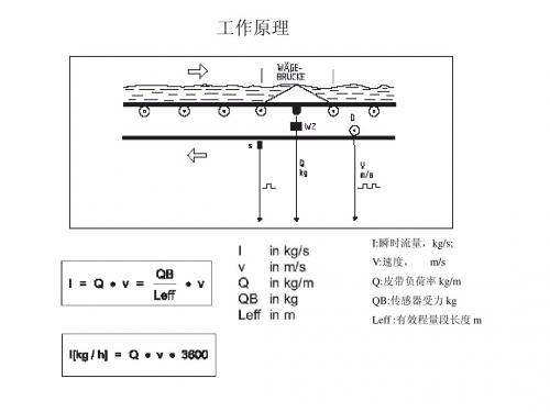
工作原理I:瞬时流量,kg/s;V:速度,m/sQ:皮带负荷率kg/mQB:传感器受力kgLeff :有效程量段长度m对于双托辊秤,有效称量段的计算方法:有效称量段长度Leff=上部显示:1#累计量计数器电源指示CPU 状态报警指示最小值指示最大值指示停止(键盘模式)起动计量(键盘模式)运行及模式指示下部显示:可选择瞬时流量,皮带负荷等故障代码计数器清零调用功能键上下光标键故障复位,删除输入更改参数键数字键返回键接受输入或进入功能块仪表显示介绍1#累计计数器(可清零)瞬时流量I瞬时流量相对值Ir 皮带负荷Q 皮带负荷相对值Qr定量值显示2#累计计数器(可清零)3#累计计数器(不可清零)皮带速度V功能菜单介绍显示故障显示检查起/停给料机服务值启用/停止键盘模式选择定量模式激活/去激活管理软件零点设定编程模式标定功能打印累计量设定时间读参数调入默认参数打印状态报告去皮重量程标定脉冲/皮带参数输入参数打印参数LB——皮带一圈脉冲测量前提条件:1,输送机运行;2,手工测量皮带转一周的时间(测三次取平均值)。
程序运行剩余时间收到的脉冲数相对于本次测量全过程的速度皮带转一圈收到的脉冲总数TW ——去皮重操作程序运行剩余时间程序运行中皮重相对于额定负荷的百分数程序完成相对于上次皮重值的偏差占额定负荷的百分比总皮重值相对于额定负荷百分比前提条件:1,输送机上空载;2,输送机运行。
>0<ZERO SET 零点设定程序剩余的时间占全部运行时间的百分比相对于额定负荷的零点误差相对上次零点标定后的偏差,占额定负荷的百分比平均零点偏差,占额定负荷的百分比程序结束显示前提条件:1,输送机上空载;2,输送机运行。
CW——量程标定操作COR=SET/ACT=标准值/实际测量值,对应参数D02,程序完成后手动修改程序运行剩余时间占全部运行时间的百分比标准值/实际测量值程序结束显示实际测量负荷占额定值百分比COR 标准值/实际测量值实物标定方法及计算公式首先将仪表累计量计数器(Z1,Z2)清零。
we make processes workContacts, CopyrightSales:Tel.:+49 (0) 61 51 32 - 10 28eMail:sales.process@Service:24h Emergency hotline:+49 (0) 172 - 650 17 00+49 (0) 171 - 255 11 95 (belt weighers, weighfeeders) eMail:service.process@Business Segments and Services:Heavy IndustryService Tel.:+49 (0) 61 51 32 - 26 23Service Fax:+49 (0) 61 51 32 - 32 70eMail:bvh.process@Light IndustryService Tel.:+49 (0) 61 51 32 - 25 72Service Fax:+49 (0) 61 51 32 - 20 72eMail:bvl.process@Mining (Vibratory Machines)Service Tel.:+49 (0) 61 51 32 - 35 25Service Fax:+49 (0) 61 51 32 - 30 96eMail:bvs.process@Transport & LogisticsService Tel.:+49 (0) 61 51 32 - 24 48Service Fax:+49 (0) 61 51 32 - 13 69eMail:bvt.process@Components & SparesService Tel.:+49 (0) 61 51 32 - 17 58Service Fax:+49 (0) 61 51 32 - 36 32eMail:bvk.process@© Copyright 2005SCHENCK PROCESS GmbHMeasuring and Process TechnologiessLandwehrstraße 55, D-64293DarmstadtAll rights reserved. Any reproduction of manual, regardless of method, without prior permission by SCHENCK PROCESS GmbH in writing,even by excerpt,is prohibited.Subject to change without prior notice.BV-H2220 GB , 0536INTECONT PLUS, Fieldbus Description© SCHENCK PROCESS GmbH, DarmstadtTable of Contents1 FIELDBUS DATA (1)1.1 Validity Range (1)1.2 Data Segments (1)1.3 Units (1)1.4 Numeric Representation (2)1.5 User Data Construction (3)1.5.1 FIXED Mode (3)1.5.2 General User Data Construction (6)1.6 User Data Diagnosis (13)1.7 Lists of Cyclic Data (15)1.7.1 Explanations on Data Lists (15)1.7.2 Commands (16)1.7.3 Preset Values in Floating Point Format (18)1.7.4 Preset Values in Integer Format (Modbus) (19)1.7.5 Status Information (20)1.7.6 Measurement Values in Floating Point Format (28)1.7.7 Measurement Values in Integer Format (Modbus) (31)1.7.8 Values in Long Integer Format (32)1.7.9 Events (33)2 PROFIBUS DP (34)2.1 Commissioning Guideline (34)2.2Profibus Module Functionality (34)2.3 User Data Construction (34)2.4Settings on DP-Slave (INTECONT PLUS) (35)2.5Settings on Profibus DP Master (35)2.6 Diagnosis and Troubleshooting (36)2.6.1 Event Message“Communication Error Host” (36)2.6.2 LEDs on Profibus Module (37)2.6.3 EasyServe Fieldbus View (37)2.7Profibus Module (VPB020V) (37)2.8 For Further Reading (38)3 DEVICENET (39)3.1 Commissioning Guideline (39)3.2 DeviceNet Module Functionality (39)3.3 User Data Construction (39)INTECONT PLUS, Fieldbus Description BV-H2220 GB , 0536I ©SCHENCK PROCESS GmbH , DarmstadtTable of Contents3.4Settings on DeviceNet Slave (INTECONT PLUS) (40)3.5Settings on DeviceNet Master (40)3.6 Diagnosis and Troubleshooting (41)3.6.1 Event Message“Communication Error Host” (41)3.6.2 EasyServe Fieldbus View (41)3.7 DeviceNet Module (VCB020V) (41)3.8 For Further Reading (42)4 MODBUS (43)4.1 Commissioning Guideline (43)4.2 Modbus Module Functionality (43)4.3 Data Format (43)4.4 Function Codes (FC) (44)4.5 Transmission Protection (44)4.6 Error Codes (44)4.7 Station Addresses (44)4.8 User Data (45)4.8.1 Process Values (45)4.8.2 Parameters (45)4.9 Cyclic Data Exchange Via Modbus (45)4.10 Sample Messages (46)4.11Settings on Modbus Slave (INTECONT PLUS) (46)4.12Settings on Modbus Master (47)4.13Diagnosis and Troubleshooting (47)4.13.1 Event Message “Communication Error Host” (47)4.13.2 EasyServe Fieldbus View (47)4.14Serial Bus Module (VSS021V) (48)4.15 For Further Reading (49)5 ETHERNET (50)5.1 Definitions (50)5.2 Configuring Ethernet Module (51)5.2.1 MultiServerTools Program (51)5.2.2 Parameterizing INTECONT PLUS (58)5.2.3 Checking Station Addresses (59)II BV-H2220 GB , 0536INTECONT PLUS, Fieldbus Description© SCHENCK PROCESS GmbH, DarmstadtTable of Contents5.3 Modbus-TCP/IP (60)5.3.1 Commissioning Guideline (60)5.3.2 Ethernet Module Functions (60)5.3.3 Fieldbus Mode (62)5.3.4 WEB Server Mode (70)5.3.5 Ethernet Bus Module(VET020V) (76)5.3.6 For Further Reading (77)5.4 Ethernet/IP (78)5.4.1 Commissioning Guidelines (78)5.4.2 Ethernet Module Functions (78)5.4.3 Fieldbus Mode (79)5.4.4WEB Server Mode (81)5.4.5 Ethernet Bus Module(VET022V) (82)5.4.6 For Further Reading (83)6 APPENDIX (84)6.1ASCII Table with HTML Codes (84)INTECONT PLUS, Fieldbus Description BV-H2220 GB , 0536III ©SCHENCK PROCESS GmbH , DarmstadtTable of ContentsIV BV-H2220 GB , 0536INTECONT PLUS, Fieldbus Description© SCHENCK PROCESS GmbH, DarmstadtFieldbus Data1 Fieldbus DataBefore putting into operation one of the protocols described below, always read Item “Fieldbus Data“ and the protocol-specific items.Decisive for the further procedure is the “User Data Construction” item. You can select:FIXED-1/2 mode orGeneral user data constructionIf one of the FIXED modes suits you,you can skip the information on IDs and parameters.The FIXED modes shorten the breaking-in time and ease the use of the fieldbus interface to a considerable extent.Simply read Items 1.1-1.4,and item FIXED MODE; the “Diagnosis and Troubleshooting”item might be useful, too.1.1 Validity RangeThis item describes all data that can be transferred using the various fieldbus protocols. The data basis is the same for all fieldbuses. Special features are detailed at the protocol-specific items.The “Fieldbus Data” item holds for the following protocols:Protocol See:Profibus DP Chapter 2DeviceNet Chapter3Modbus Chapter4Modbus-TCP/IP and Ethernet/IP Chapter 5For description of protocol S5-RK512 (3964R), see manual FH458.1.2 Data SegmentsThe INTECONT PLUS system distinguishes the following cyclic data:Commands (bit or byte information)Setpoints(floating point values)Status information (bit or byte information)Measurement values (floating point values)Long (INT32) values (integer values)1.3 UnitsINTECONT PLUS uses two different unit systems:SI unitsNON-SI unitsChangeover takes place using the “Units” parameter.For the fieldbuses, this means:Selection SI lets you transfer all unit values in "m, kg and sec"Selection NON-SI transfers your values in "ft, lb and sec".INTECONT PLUS, Fieldbus Description BV-H2220 GB , 05361©SCHENCK PROCESS GmbH , DarmstadtFieldbus Data 1.4 Numeric RepresentationFloating Point ValuesINTECONT PLUS readies measurement values, setpoints and some parameters in the form of floating point numbers in the IEEE-754 4-byte format. Depending on protocol and parameter, these can be converted into another floating point format. For details, see individual protocol descriptions.Transmission always starts with MSB.Example for transmission of value 150.5in IEEE format (indicating the line sequence):Byte 1: Sign/ExponentByte 2:Mantissa1Byte 3:Mantissa 2Byte 4:Mantissa30x430x160x800x00 Sample floating point numbersNumber IEEE format (HEX)Siemens-KG format (HEX) 1.03F8000000140000010.04120000004500000100.042C80000076400001000.0447A00000A7D0000Data (double) wordsData words are standard transmitted using the Motorola format(high byte followed by low byte).Depending on protocol and parameter, another byte sequence can be set. For details, see individual protocol descriptions.Data type MSB LSBInt 32 / LONG MSB LSBInt 1600MSB LSBBit informationBits are comprised to form words (Modbus, Modbus/TCP) or double words (Profibus, DeviceNet). The line sequence is as follows:Ex.: Command ID 0x0140Comm4_HI Comm4_LO Comm5_HI Comm5_LOEx.: Status ID 0x02F0Status2_HI Status2_LO Status3_HI Status3_LO2BV-H2220 GB , 0536INTECONT PLUS, Fieldbus Description© SCHENCK PROCESS GmbH, DarmstadtFieldbus Data1.5 User Data ConstructionAs mentioned above, INTECONT PLUS readies two process images: FIXED-1/2 mode or General user data construction.The Fixed modes let you transfer specified data in specified positions from host system to INTECONT PLUS and vice versa.The FIXED mode is not designed for parameter transfer and data configuration.The advantage is that profound learning of the principle of data exchange using the “General User Data Construction”is omitted. This principle enables any data(including system parameters) to be transferred in any sequence, however, the price for this flexibility is the exhaustive breaking-in concerning data extent and type of processing.The user data constructions of this item apply to the PROFIBUS and DeviceNetprotocols. The Modbus, or Modbus/TCP, protocol is used to transfer continuous data ranges from Master to scale and vice versa (see protocol-specific items).1.5.1 FIXED ModeThe data of FIXED-1 mode are optimised for continuous operation; those of FIXED-2mode are provided for batching. In addition, the data are matched to the particular scale type. The construction of the data packages is identical for the two modes (see below). Every value has the size of one data double word (4 bytes).Values not used are filled with zero. For detailed description of commands and status values, refer to the lists of cyclic data given at the end of the Fieldbus Dataitem.NOTEpreset value 1 (commands 4 + 5) the release bit (in terms of a fieldbus lease)serving for interface monitoring must always be set statically. If this bit The table below includes all values transferred with the particular scale type:In re is not set, the subsequent preset values are not evaluated and HOSTommunication fault is set.c INTECONT PLUS, Fieldbus Description BV-H2220 GB , 05363©SCHENCK PROCESS GmbH , DarmstadtFieldbus Data4BV-H2220 GB , 0536INTECONT PLUS, Fieldbus Description© SCHENCK PROCESS GmbH, Darmstadt1.5.1.1 FIXED Mode – Detailed Message SampleINTECONT PLUS parameters (scale type:VLW)Configuration FIXED-1Floating point format IEEE formatMaster->Slave Bytes (hex) Meaning (ID value, hex) Current valueBytes 1-4 00 0C 00 00 Commands 4+5(0140)Event acknowledged,release set Bytes 5-8 00 00 00 00Commands 6+7(0160)No command activeBytes 9-12 00 00 00 01Commands 8+9(0180)START keyboard mode set Bytes 13-1643 16 80 00Setpoint(0250)150.5kg/hrBytes 17-2042 C8 00 00 Batch setpoint(0252)100kgBytes 21-32ZERO StandbySlave->Master Bytes (hex) Meaning (ID value, hex) Current valueBytes 1-401 02 00 00Status 2+3 (02F0)Normal mode, no releaseBytes 5-8 00 02 00 04Status 4+5 (0310)Filling system, fill level < Min Bytes 9-12 13 18 00 00Most significant error(0610)Event S9 ackn.,Warning2Bytes 13-1642 C8 00 00 Feed rate actual value(0750)100kg/hrBytes 17-2044 9A 40 00 Totalizing counter 1(0752)1234kgBytes 21-2443 AC 80 00Bin level F(0760)345kgBytes 25-2845 F6 90 00Totalizing counter 2(0754)7890kgBytes 29-3242 C8 00 00 Effective setpoint(0766)100kg/hr1.5.2 General User Data ConstructionSince there is no specific Weighing profile, data construction uses the existing Variable Speed Drives profile.In this profile, user data construction for the cyclic channel is called Parameter Process Data Object (PPO).The guideline determines the user data construction for drives a Master can use to access the drive slaves by means of cyclic data er data construction in cyclic data exchange comprises two ranges which can be transmitted in every message:• Process Data Range (PZD), i.e. control words and setpoints,or status information and actual values• Parameter Range (PKW) for read/write of parameter values, e.g. read-out of information on parameter characteristics (MIN/MAX values,etc.).The PPO type used to address the scale from Master can be configured at the time of bus system commissioning. The PPO type is selected as a function of the scale task in the automation environment and used to control the scale in the automation environment, e.g.Start/Stop, Enter Setpoints. The parameter range enables the user to freely access all scale parameters with the use of the bus system.Thus, further information for scale visualization can be called up from a host system, e.g. a PC, with no adverse effects on the efficiency of process data transmission.All messages used in cyclic data transmission have the following basic construction:Protocol frame (header)Parameters (PKW)optionalUser dataProcess data (PDR)Protocol frame(trailer)General message constructionPPO typesThe following PPO types can be defined:User data without parameter range,with three specified preset values and max. 6 additional read values selectable via IDUser data with parameter range, two preset values and four read values.Parameter range (PKW)The PKW message part (Parameter Code Value) can be used to monitor and/or change any scale parameter. The requisite mechanisms of order/reponse IDs are described at the Parameter Transfer item.Process data range (PDR)Using the process data, commands and preset values (Master to scale) or status words and actual values ( scale to Master response) can be transmitted.Transmitted process data are immediately effective..6BV-H2220 GB , 0536INTECONT PLUS, Fieldbus Description1.5.2.1 Message ConstructionThe figure below shows the basic construction of user data in the INTECONT PLUS system.The first line shows the message from bus master to scale; the second, thescale reponse.User data construction of messageshe maximum size of a user data package is 32 bytes,the construction is invariable,data contents (IDs and values) are variable.NoteWhen using the DeviceNet protocol for transmission, always use 32 bytes as produced and consumed connection size.SampleData transmission without parameters with 3 preset values, 6 variable user-defined identifications (IDs) – representation HEXT Not cle. CONTPLUS), fieldbus communication fault is set on INTECONT PLUS. INTECONT eThe preset IDs from Master to scale must originate from the Command or Presetvalue ranges. It is possible to preset multiple setpoints (feed rate and batch setpoint) or multiple commands with different IDs in one and the same cy If one ID is zero, respective value is not evaluated..If all bytes are set to zero in the presetting message (bus Master to INTE PLUS interprets this state as failure of the bus Master's host CPU whilst the communication processor in Master is active. The INTECONT PLUS timeout monitoring cannot compensate this state since formally valid data packages are transferred still. At least one preset ID must have a valid value unequal to zero.Control and status information is comprised in 4-byte packages. The IDs assignedto blocks are highlighted in data description. Only these IDs may be used here. If a different ID is used, data are rejected and an error message is output. In the response message, status and actual value are identified by their positions, ID 0x750. Through addition of (read) IDs in Master --> scale message,you can cause thed values into the response message. Value sequence corresponds to the ID sequence. If IDs of the Preset value or Command ranges re red a s If an ID is identified as wrong, corresponding value in the response is set to zero.le r et rey) parameter block always precedes the residual data. in message. The fixed status has ID 0x2F0; the actual value scale to enter the desire a ente , the v lue pre et last is reread. Samp Data t ansmission with additional param er blockThe (g Master --> scale messagePKEINDPWE1PWE2ID Preset value 1Preset value 1IDPresetvalue 2Preset value 2 Ordering list(read IDs)Scale responsePKEINDPWE1PWE2Status infos (2+3)(4 bytes)Actual value (4 bytes)Values as per ordering listNoteParameter evaluation requires considerable expenditure.We suggest to limit dataexchange to parameters of the FLOAT type.For detailed message samples, see end of item 1.5.8BV-H2220 GB , 0536INTECONT PLUS, Fieldbus Description1.5.2.2Parameter TransferParameter block (PKW)Parameter block (PKW), 4 wordsPKE (1st word)IND (2nd word) PWE (3rd and 4th words)High Low PWE1PWE2Basic construction of parameter blockParameter ID (PKE),1st word The parameter ID (PKE) is always a 16-bit value.Bits 0 to 12 (PNU) include the number of the desired parameter.Bits 13 to 15 (AK)include the order or response ID.For the order message (Master scale), the meaning of the order IDis shown in table.For the response message (scale Master), the meaning of theresponse ID is shown in table. Depending on order ID, only certainresponse IDs can be used.AK PNUBit no. 151413Bit 0-12 Details of parameter ID (PKE)Order ID Meaning Pos. response Neg. response 0No order0-271Request currentparameter value (doubleword)273Write (change) parametervalue (double word)274Order description element(double word)Order IDs (AK)Master station —> INTECONT PLUSResponse ID Meaning0No order2Transfer current parameter value/ event group (double word) 7Order cannot be executed (error number in PWE2) Response IDs (AK)INTECONT PLUS —>Master stationParameter index (IND)2nd wordThe array sub-index (in PROFIBUS profile simply called “sub-index) isan 8-bit value and transferred upon cyclic data exchange using PPOsin the most significant byte(bits 8 to 15)of parameter index (IND). Theless significant byte (bits 0 to 7) always has zero value.IND functionIf an order transfers a sub-index with values between1 and 254, thedesired index of the selected parameter is transferred.For meaningsof single parameter indices, please see the table below.When a description element is processed,the number of the desiredelement is transferred.Index Meaning0Default value4Min. value8Max. value12Unit index(1st word), after-comma places (2nd word)Index in parameter description (IND) – most significant byte of parameter index Parameter value (PWE)3rd and 4th wordsThe parameter values (PWE) are always transferred in form of adouble word (32 bits). A PPO message can transfer only oneparameter value at a time.A 32-bit parameter value consists of PWE1 (most significant word, 3rdword) and PWE2 (less significant word, 4th word).A 16-bit parameter value is transferred in PWE2 (less significantword, 4th word). Set PWE1(most significant word, 3rd word)to 0 valueon Master.Bits 0 ... 15:Parameter value with 16-bit parameter, or Low portion with32-bit parameterBits 16 ... 31:Value= 0with 16-bit parameters, or High portion with 32-bitparameterError number Meaning1Inadmissible parameter number (parameter not available or presetvalue wrong, e.g. MIN/MAX exceeded up/down)2MIN/MAX value exceeded up/down3No access right4Order not possible in current operating state of scale5Order not implementedError numbersError number (PWE2)If the response ID has value 7 (order cannot be executed), parameter value 2 (PWE2) includes an error number specified in table.10BV-H2220 GB , 0536INTECONT PLUS, Fieldbus DescriptionOrder/response processing rulesAn order and/or response can refer to a single parameter only.The Master must repeat the order until receipt of relevant response.The Master recognises the response on the given order through:evaluation of response IDevaluation of parameter number PNUif necessary, evaluation of parameter index INDif necessary, evaluation of parameter value PWE.The complete order must be sent in one message; splitted order messages are not admitted. The same applies to the response.If the response message is repeated, the scale responds with the current values.If no information from PWK interface are needed in cyclic operation (only PZD data matter), set the order ID to “No Order”.For samples, see item below.1.5.2.3 General User Data Construction – Detailed SamplesSample 1GSD module:"NO_PARA_ID"INTECONT PLUSConfiguration: “NO_PARA_ID”parametersProcess image length Master -> Slave : 30 bytes, Slave -> Master: 32 bytesFloating point format Siemens-KG-FormatSample Master->Slave process image:Bytes 1+2 0250ID for"Write feed rate setpoint”Bytes 3-6 0A 7D 00 00 Setpoint 1000.0kg/hrBytes 7+8 0140ID for"Commands 4+5"Bytes 9-1 00 41 00 00 Reset control value for scale start and counter 1Bytes 13+14 0000StandbyBytes 15-18 00 41 00 00 Reset control value for scale start and counter 1 (ID=0: not active)Bytes 19+20 0752ID to request counter 1 readingBytes 21+22 075C ID to request belt speed in m/sBytes 23+24 0754ID to request counter 2 readingBytes 25+26 0758ID to request belt load in kg/mBytes 27+28 0000StandbyBytes 29+30 0000StandbySample Slave->Master process image:Bytes 1-4 01 02 00 00 Always status messages to ID 02F0Bytes 5-8 00 00 00 00 Always feed rate actual value kg/hr, ID=0750Bytes 9-12 00 00 00 00 Value for ID in bytes 19+20, i.e.counter 1 readingBytes 13-16 00 00 00 00 Value for ID in bytes 21+22, i.e. belt speedBytes 17-20 00 00 00 00 Value for ID in bytes 23+24, i.e.counter 2 readingBytes 21-24 00 00 00 00 Value for ID in bytes 25+26, i.e. belt loadBytes 25-28 00 00 00 00 StandbyBytes 29-32 00 00 00 00 StandbyBytes 1-4 status messages: set are "Normal mode” and “No release” bits-----------------------------------------------------------------------------------------------------------------------------------------------Sample 2 (preset parameter)GSD module:“PARA_ID”Configuration: “PARA_ID”INTECONT PLUSparametersProcess image lenght Master -> Slave : 28 bytes, Slave -> Master: 32 bytesFloating point format IEEESample Master->Slave process image:Bytes 1-8 7205 0000 4170 0000 Preset parameter"F_Control Min.– Feed Index 1" (value =15 %) Bytes 9+100250ID for"Write feed rate setpoint "Bytes 11-14 44 7A 00 00 Setpoints 1000.0kg/hrBytes 15+16 0140ID for"Control"Bytes 17-20 00 44 00 00 Acknowledge control value for events and reset counter 1Bytes 21+22 0752ID to request counter 1 readingBytes 23+24 075C ID to request belt speed in m/sBytes 25+26 0754ID to request counter 2 readingBytes 27+28 0758ID to request belt load in kg/mSample Slave->Master process image:Bytes 1-8 5205 0000 4170 0000 Preset parameter value acceptedBytes 9-12 01 02 00 00 Always status messages to ID 02F0Bytes 13-16 00 00 00 00 Always feed rate actual value in kg/h,ID=0750Bytes 17-20 00 00 00 00 Value for ID in bytes 19+20, i.e.counter 1 readingBytes 21-24 00 00 00 00 Value for ID in bytes 21+22, i.e. belt speedBytes 25-28 00 00 00 00 Value for ID in bytes 23+24, i.e.counter 2 readingBytes 29-32 00 00 00 00 Value for ID in bytes 25+26, i.e. belt load-----------------------------------------------------------------------------------------------------------------------------------------------Sample 3 (preset parameter with error response)GSD module“PARA_ID”Configuration: “PARA_ID”INTECONT PLUSparametersProcess image lengths Master -> Slave : 28 bytes, Slave -> Master: 32 bytesFloating point format IEEESample Master->Slave process image:Bytes 1-8 7205 0000 447a 0000 Preset parameter"F_Control Min." (value =1000 %) .........Sample Slave->Master process image:Bytes 1-8 F205 0000 4170 1000 Preset parameter value not accepted (value > MAX) .........-----------------------------------------------------------------------------------------------------------------------------------------------Sample 4 (read parameter)GSD module“PARA_ID”INTECONT PLUS parameters Configuration: “PARA_ID”Process image lengths Master -> Slave : 28 bytes,Slave -> Master: 32 bytesFloating point format IEEESample Master->Slave process image:Bytes 1-8 3205 0000 xxxx xxxx Read parameter "F_Control Min" (xxxx = optional value) .........Sample Slave->Master process image:Bytes 1-8 5205 0000 4170 0000 Parameter value = 15%.........12BV-H2220 GB , 0536INTECONT PLUS, Fieldbus Description1.6 User Data DiagnosisEasyServe readies a very simple form of bus monitor.Menu “Fieldbus View”lets you go to the dialog window.The following diagnoses are possible:Display of first 50 characters of last 50 messages in hex format. Display only shows the mere user data.The following errors can be recognised:Parameter with wrong data format. All floating point numbers are improperlyindicated.Faulty IDs preset from Master (see Lists of Cyclic Data) Faulty data contentsNot recognised: Initialisation error upon connection set-up Layer 2 issues upon dataexchangeDisplay of EasyServe monitor (Profibus or DeviceNet)Representation of Modbus messages (incl Modbus frame)” bit and command D=0x0160).Scale is requested to respond to IDs 0x0758,0x075E,0x0310 and Explanations on EasyServe monitor (Profibus sample)Master transfers command (ID=0x0140) “Acknowledge event (I 0x0610.Display meaningsDis “==“<=aster uttonsR Starts recording on scaleData are transferred from scale to PC and then displayed. This process may take some seconds depending on how many data have been stored yet. Maximum the t (most recent) 50 messages can be recorded.k all (no selection), single or a group of messages by mouse click and copy them into clipboard. If requested, data can be copied into an editor. Checkbox:Lets you select the direction of data and activate a time stamp.NoteWith the Modbus/TCP protocol, the EasyServe monitor displays the data of the internal interface (scale-EtherNet module). The representation corresponds to the Modbus sample.play shows current fieldbus protocol (see title) and data selected using checkbox.> “ means that Master sends data to scale ( Receive INTECONT PLUS).= “ identifies data sent from INTECONT PLUS to M Selection b ecord :Display :las Copy :Lets you mar 14BV-H2220 GB , 0536INTECONT PLUS, Fieldbus Description1.7 Lists of Cyclic Data1.7.1 Explanations on Data ListsThere are separate lists for the various data types.Each list contains the following information:IDUsed with protocols:Modbus for data addressModbus/TCP for data addressProfibus DP for ID indicating the value to be transferredDeviceNet s.ProfibusThe “ID” value addresses the complete data word. If a bit is to be addressed (as is possible with MODBUS), add the number before value meaning to the word address.e.g.:General alarm (data segment "Status")Word address 0x02F0+ 5 --> bit address 0x02F5The bold-printed IDs shall be used for:Profibus DPDeviceNetThey determine the base address of a double word.ValueThe "Value" column states the meaning of the value in the INTECONT PLUS system.Scale typesThe “Type” column indicates whether or not the respective value is available with the selected scale type.If not available, ZERO value is returned. Preset values relating to non-existing IDs are not evaluated.Note:Non-existing values are possibly available in a later software version (new extension stage).Mode (commands only)Commands can be triggered by level or edge. Letter “D(ynamic)“ indicates that a change from “0” to “1” triggers the desired action. Letter “S(tatic)“ indicates that the level determines the function.INTECONT PLUS, Fieldbus Description BV-H2220 GB , 053615©SCHENCK PROCESS GmbH , Darmstadt。


申克失重秤使用手册1.概述什么是INTECONT仪表?是可用于皮带秤,固体流量计,质量流量计,质量给料机,给料机,失重式给料机的计量计算系统。
该系统又三种变形:1.标准情况下,不用选项卡。
2.当有额外输入输出活打印机时,用VFE610V选项卡。
3.现场总线的选项卡VSS021V: Modbus/S5VPB020V: ProfibusVCB020V: DeviceNetVET020V: MODBUS/TCP本手册适用于失重式给料机的计量和控制。
1.卸料:控制(失重式)2.卸料:测量3.平台负载:控制(增量式)4.平台负载:测量更多内容,见Fieldbus 操作手册BVH2220S5-RK512 (3964R)FH 458Modbus (Compa)FH 525显示:荧光显示,6毫米字元高度上段显示左侧:运行信息右侧:设定流量单位:kg/h 或t/h总未料量单位:kg 或t下段显示左侧:故障信息右侧:可选则的流量,速度等采用美国单位时,显示有所改变信号灯(发光二极管)2个绿色和3个红色绿色:准备好红色:错误或限值的讯息键盘:可触摸性薄膜启/停选择低段显示选择功能复位调入分配功能和故障文本确认故障信息, 删除输入退出功能开始功能确认输入准备输入,如设定值输入参数输入符号和小数点儿定义:I =流量单位: kg/h 或t/h 单位时间内通过皮带的物料量P=流量设定值单位:kg/h 或t/h 根据设定值控制实际值Z=喂料量单位:kg 或t 喂料量=喂料速率×喂料时间F=平台负载单位:kg 或tFr=物料重量在总量中的百分比单位:%Nom. Amount Fo=料斗和物料总重量Y=控制器调节量单位: mAXd=控制偏差N=电机转速单位:1/m重力: 控制模式容积: 非控制模式失重式计量原理:用称重传感器测量满载的料斗,规定单位时间内的重量。
结果与单位Ma内的速度相同。
通过喂料预设的设定值计量控制喂料速率。

1、目录1、概述 (1)讲述皮带秤操作原理及具体情况,如“出料点供料”。
什么是INTECONT? (1)详细资料 (1)定义 (1)计量原理 (1)控制 (2)输入和输出 (3)2、技术数据和字符 (5)本章简要介绍INTECONT 所用全部数据和所有可能发生的情况。
技术数据 (5)接口 (6)对话语言、单位 (7)显示、指示灯 (7)程序设置、标定 (8)3、程序设置 (9)程序设置功能便于以少量的运算完成秤体计量要求。
功能分配 (9)标定功能 (9)皮带环行LB (10)除皮TW (10)置零 (11)砝码检查CW (12)模拟方式 (13)时间设置.......................................... 13 4、服务值 (14)服务值信号适用外部线缆、输入、输出转换和负荷传感哭负载等检查。
另外,SPC值(生产过程控制统计)可用于喂料记录等方面。
5、参数 (15)确定设备特性,参数可满足特殊要求,甚至在停电时,他们亦能无限期的存贮。
总述 (17)调入参数 (17)装入初始参数 (18)参数概述 (19)注解参数表 (22)6、出现事件信号后错误诊断(故障信息) (45)大多数错误以及大部分操作状态均以事件信号的形式出现。
错误查询表帮助操作者迅速找出错误并及时恢复正常操作状态。
系统信息S...S9 (45)物料流量B...B9 (45)电气系统E...E5 (46)标定C1...C3 (46)最大值H1...L4 (46)最小值L1...L4 (47)信号灯 (47)7、使用 (48)全面介绍,逐步解释了应该进行的工作。
另外,你还会发现可能隐含的错误。
操作学习 (48)机械要求 (49)电器要求 (49)输入参数 (50)控制 (51)功能检查 (52)标定 (53)用砝码检查 (53)带速检查 (54)物料检查 (54)测试插座 (55)机械部分安装与调试 (55)1、概述什么是INTECONT?INTECONT PLUS是用于计量、控制、喂料设备的计量计算系统。
申克皮带秤标定方法
1. 嘿,你知道申克皮带秤咋标定吗?就好比你要给汽车校准速度表一样,得有正确的方法呀!比如说,先把秤体清理干净,这就像给运动员打扫好赛道,才能更好地发挥呀!
2. 申克皮带秤的标定,可没那么简单哦!就像开锁,得找到合适的钥匙。
比如要检查各个部件是否正常,这不就和考前检查文具一样重要嘛!
3. 哇塞,申克皮带秤标定的时候要注意好多细节呢!好比做精细的手工,稍有不慎就前功尽弃啦。
像设定参数,那可不能马虎呀!
4. 你想想,申克皮带秤标定不好会咋样?那不就像导航出错,会走冤枉路呀!所以说要严格按照步骤来,比如砝码的放置就得准确无误。
5. 哎呀呀,申克皮带秤的标定可真是个技术活呀!就如同画画,每一笔都得恰到好处。
比如调整零点,这可不是随便弄弄就行的哦!
6. 申克皮带秤标定要这么做才对呀!这好比治病,得对症下药才行。
像检查传感器,不就像给病人做检查找病因吗?
7. 哼,申克皮带秤标定可不是闹着玩的!像走钢丝一样,得小心翼翼。
就拿校准皮带速度来说,稍有差池都不行啊!
8. 哇哦,申克皮带秤的标定居然有这么多讲究!仿佛一场精彩的魔术,每个环节都不能出错。
像选择合适的标定物料,这多关键呀!
9. 申克皮带秤标定一定要认真对待呀!这就像建房子打地基,基础不稳可不行。
我的观点结论:申克皮带秤的标定是非常重要且需要严谨对待的,只有掌握正确的方法,注意每个细节,才能确保其精准度和可靠性。
申克仪表说明书控制方式:本地控制方式(键盘模式)/远程控制方式(非键盘模式)标定模式:容积模式(标定模式)/重量模式(非标定模式)按键说明启动停止选择上下显示器显示内容,选择功能复位计数器相当于FUNC键。
调用分配功能和时间按信息相当于DEL键,应答事件信息删除输入数字相当于ESC键,退出功能相当于ENT键,确认输入有效1、开启键盘模式:将仪表设为本地模式(键盘模式):由现场操作,中控不能操作。
按菜单键“”进入主菜单。
然后用上下键找到“Start Keyboard Mode”按确认键“”。
此时仪表左上方会出现一个小方格。
说明在键盘模式。
2、关闭键盘模式:按菜单键“”进入主菜单。
然后用上下键找到“Stop Keyboard Mode”按确认键“”。
此时仪表左上方小方格会消失。
说明在非键盘模式。
此时仪表将由中控控制。
3、开启容积模式:容积模式为标定模式,只有在标定、去皮和做环形时才用。
按菜单键“”进入主菜单。
然后用上下键找到“V olu Mode”按确认键“”。
仪表左上方小方格内会出现一个“v”字。
说明在容积模式。
4、关闭容积模式:即开启重量模式。
按菜单键“”进入主菜单。
然后用上下键找到“Gravimetric”按确认键“”。
仪表左上方小方格内“v”字会消失。
说明在重量模式。
仪表启停:必须在键盘模式下,设备允许开启。
按启动键即可启动设备。
按停止设备。
设置参数(慎用):按菜单键进入菜单,用上下键找到Programming 菜单。
确认键进入。
用上下键和确认键找到相应的参数。
当需要修改参数时,找到相应的参数,按修改键,后用数字键或山下建直接修改即可。
去皮:确保传感器正常,设备无料。
控制方式打到键盘和容积模式,给定到三倍额定量程。
开启设备。
观察变频器在五十赫兹恒定。
用菜单键进入菜单,进入标定程序Calib. Functions。
确认键进入,找到去皮TW :Tare 功能,确认键开始去皮,系统会自动倒计时,结束后,按确认键确定去皮结束。
皮带说明书皮带说明书1. 介绍皮带是一种用于传输动力或运输物品的装置。
它是由一个灵活的带状材料制成,通常由织物、橡胶或金属制成。
皮带广泛应用于各个行业,如机械制造、采矿、冶金、建筑等。
本说明书将介绍皮带的主要特点、使用方法和维护保养事项,以帮助用户更好地了解和使用皮带。
2. 特点皮带具有以下特点:- **灵活性强**:皮带具有较高的柔韧性,能适应不同形状的传动装置。
- **传输效率高**:皮带在传输动力时的效率较高,能够有效减少能量损失。
- **耐磨性强**:皮带通常采用耐磨材料制成,能够长时间保持良好的使用状态。
- **操作简便**:使用皮带进行传动时,安装和调整相对较简单,维护保养也比较方便。
3. 使用方法使用皮带时,需要注意以下几点:3.1 安装在安装皮带时,需要确保皮带正确安装到传动装置上。
首先,松开传动装置的张紧机构,将皮带放置在滚轮上,然后调整张紧机构,使皮带适度紧固。
在安装过程中,应注意避免皮带扭曲或过紧,以免影响正常传动。
3.2 调整在使用皮带进行传动时,传动装置的对中调整非常重要。
确保滚轮对中,在传动过程中皮带不会偏移或发生跳跃。
同时,还应注意调整张紧机构,保持恰当的皮带张力,以确保传动效果最佳。
3.3 检查定期检查皮带的磨损程度是必要的。
如果发现皮带出现明显的磨损或损坏,应及时更换。
此外,还应检查皮带是否松弛,并进行适当的调整。
保持皮带的良好状态能够延长其使用寿命。
4. 维护保养为了确保皮带的正常运行,应定期进行维护保养。
以下是一些建议:- **清洁**: 定期清洁皮带表面的灰尘和污垢,可以使用软刷和清洁剂。
- **润滑**: 对于一些需要润滑的皮带,应定期进行润滑。
使用适当的润滑剂,注意不要涂抹过多。
- **张紧**: 定期检查皮带的张紧程度,如果松弛,应调整张紧机构进行紧固。
- **更换**: 当发现皮带磨损严重或出现断裂时,应及时更换新的皮带。
5. 安全注意事项在使用皮带时,需要注意以下安全事项:- **禁止触摸**: 在运行中的皮带附近,切勿用手触摸或操作,以免造成伤害。