INTRODUCTION ON CIRCUIT SIMULATION TECHNIQUES.ppt
- 格式:ppt
- 大小:317.50 KB
- 文档页数:41
Module 21: Circuit SimulationModule 21: Circuit Simulation21.1Circuit Simulation...........................................................................21-121.1.1Model Types.................................................................................................21-121.1.2Exercise/Demo.............................................................................................21-221.1.3Adding the voltage sources..........................................................................21-521.1.4Setting up the analyses................................................................................21-721.1.5Setting up a Transient/Fourier analysis........................................................21-821.1.6Setting up an AC Small Signal analysis.......................................................21-921.1.7Running the simulation...............................................................................21-1021.1.8Running a Parameter Sweep Analysis.......................................................21-1221.1.9Using Advanced Options............................................................................21-1421.1.10Using a SPICE netlist for simulation..........................................................21-15Software, documentation and related materials:Copyright © 2008 Altium Limited.All rights reserved. You are permitted to print this document provided that (1) the use of such is for personal use only and will not be copied or posted on any network computer or broadcast in any media, and (2) no modifications of the document is made. Unauthorized duplication, in whole or part, of this document by any means, mechanical or electronic, including translation into another language, except for brief excerpts in published reviews, is prohibited without the express written permission of Altium Limited. Unauthorized duplication of this work may also be prohibited by local statute. Violators may be subject to both criminal and civil penalties, including fines and/or imprisonment. Altium, Altium Designer, Board Insight, Design Explorer, DXP, LiveDesign, NanoBoard, NanoTalk, P-CAD, SimCode, Situs, TASKING, and Topological Autorouting and their respective logos are trademarks or registered trademarks of Altium Limited or its subsidiaries. All other registered or unregistered trademarks referenced herein are the property of their respective owners and no trademark rights to the same are claimed.Module Seq = 2121.1 Circuit SimulationThe Altium Designer-based Circuit Simulator is a true mixed-signal simulator, meaning that it can analyze circuits that include both analog and digital devices.The Simulator uses an enhanced version of the event-driven XSpice, developed by the Georgia Tech Research Institute (GTRI), which itself is based on Berkeley's SPICE3 code. It is fullySPICE3f5 compatible, as well as providing support for a range of PSpice® device models. 21.1.1 Model TypesThe models supported by the Simulator can be effectively grouped into the following categories.21.1.1.1 SPICE3f5 analog modelsThese are predefined analog device models that are built-in to SPICE. They cover the various common analog component types, such as resistors, capacitors and inductors, as well as voltage and current sources, transmission lines and switches. The five most common semiconductor devices are also modeled - diodes, BJTs, JFETs, MESFETs and MOSFETs.A large number of model files (*.mdl) are also included, that define the behavior of specificinstances of these devices.21.1.1.2 PSPICE analog modelsThese are predefined analog device models that are built-in to PSpice. To support these models, changes have been made to the general form for the corresponding SPICE3f5 device and/or additional parameter support has been added for use in a linked model file.Note: These models are not listed separately in this reference. PSpice support information is included as part of the information for the relevant SPICE3f5 device model.21.1.1.3 XSPICE analog modelsThese are predefined analog device code models that are built-in to XSpice. Code models allow the specification of complex, non-ideal device characteristics, without the need to develop long-winded sub-circuit definitions that can adversely affect Simulator speed performance. Thesupplied models cover special functions such as gain, hysteresis, voltage and current limiting and definitions of sdomain transfer functions.The SPICE prefix for these models is A.21.1.1.4 Sub-Circuit modelsThese are models for more complex devices, such as operational amplifiers, timers, crystals, etc, that have been described using the hierarchical sub-circuit syntax.A sub-circuit consists of SPICE elements that are defined and referenced in a fashion similar todevice models. There is no limit on the size or complexity of sub-circuits and sub-circuits can call other subcircuits. Each sub-circuit is defined in a sub-circuit file (*.ckt).The SPICE prefix for theses models is X.21.1.1.5 Digital modelsThese are digital device models that have been created using the Digital SimCode™ language. This is a special descriptive language that allows digital devices to be simulated using an extended version of the event-driven XSpice. It is a form of the standard XSpice code model. Source SimCode model definitions are stored in an ASCII text file (*.txt). Compiled SimCode models are stored in a compiled model file (*.scb). Multiple device models can be placed in the same file, with each reference by means of a special "func=" parameter.The SPICE prefix for theses models is A.Digital SimCode is a proprietary language - devices created with it are not compatible with other simulators, nor are digital components created for other simulators compatible with the Altium Designer-based mixed-signal Simulator.21.1.2 Exercise/Demo1. Select File » New » PCB Project from the menus.2. Rename the new project file (with a .PrjPCB extension) by selecting File » Save Project As.Navigate to a location where you would like to store the project on your hard disk, type the name Filter.PrjPCB in the File Name field and click on Save.3. Select File » New » Schematic. A blank schematic sheet named sheet1.SchDoc displays inthe design window of the Schematic Editor and the schematic sheet is now listed underSource Documents beneath the project name in the Projects panel.4. Rename the new schematic file by selecting File » Save As.5. Now we can create the Filter circuit shown below in figure 86. Before we can run a simulation,the schematic must contain components with SIM models attached, voltage sources to power the filter, an excitation source, a ground reference for the simulations and some net labels on the points of the circuit where we wish to view waveforms.Note: This project is available in the Altium Designer circuit simulation examples.Figure 1. Circuit to simulateNote: The Altium simulator supports Spice 3F5 models and PSPICE models. SPICE models used for circuit simulation (.ckt and .mdl files) are located within the integrated libraries in theC:\Program Files\Altium Designer Summer 08\Library folder. You must use the correct file extension for each model type.Tip: A circuit for simulation must always have a path to ground. If it doesn’t you’ll receive iteration limit reached error. To fix this provide a path to ground or modified the advanced options value for RSHUNT to a figure of around 2-4Meg. Remember that the simulator assumes Capacitors are perfect, i.e. no leakage.6. Click on the Search button in the Libraries panel.7. To search for all LF411 type components, in all supplied libraries, enter LF411 in the upperpart of the Libraries Search dialog. Set the Scope to Libraries on Path, and set the Path to C:\Program Files\Altium Designer Summer 08\Library, with the IncludeSubdirectories option enabled. Note that this will find all LF411 type components, you can check if the chosen component includes a Spice model by selecting it in the Libraries panel, and noting if there is a simulation model detailed in the Model Name region of the panel. Note: to search for only components that include a simulation model, you would have used the search string (Name like '*LF411*') and HasModel('SIM','*',true)8. You may want to use a simulation model in your design other than the one already suppliedwith the component in its integrated library. If you download a model file from amanufacturer’s website, it is recommended that you copy it into your design’s project folder. For the sake of this example, we will remove and re-add the SPICE model, LF411C.ckt.9. Copy LF411C.ckt and paste this file into the folder where your project files reside usingwindows Explorer. If you have created the circuit from scratch, there is a copy of the model file in C:\Program Files\Altium Designer Summer 08\Examples\CircuitSimulation\Filter.10. Add the model file to the project by selecting the project name (Filter.PrjPCB) in the Projectspanel, right-click and select Add Existing to Project. Choose the model file and click Open.11. Double-click on the op amp to open its Component Properties dialog. Delete the existing SIMmodel in the Models section by selecting it and clicking on Remove and confirming thedeletion.12. Click on Add in the Models section to display the Add New Model dialog.13. Select Simulation from the Model Type drop-down list and click OK. The SIM Model-General/Generic Editor dialog displays.14. Select Spice Subcircuit from the Model Sub-Kind list, the Spice Prefix will automatically setto X. Note that the dialog name has changed to reflect the Model Sub-Kind.15. Click the Browse button to open the Browse Libraries dialog. Because you have added themodel file to the project it will automatically be available, select the LF411C.ckt model from the list and click OK to close the dialog.Note: The Model Name detailed in the Model Kind tab is not the name of the file, it is actually matched against the name found in the .SUBCKT statement in the model file. CKT files can contain multiple .SUBCKT sections so be careful the correct name is specified.16. The final step is to configure the pin mapping from the model to the schematic symbol(generic numbering is used in Spice model files, not physical pin numbers). Click on the Port Map tab of the SIM Model-General / Spice Subcircuit dialog to show the current mapping, and the Model File tab to show the generic numbers used in the .SUBCKT statement in the model file.Figure 2. Port Map information for sub-circuit simulation model17. Modify the Model Pin mapping by selecting the matching pins from the Model Pin drop-downlists, as shown in Figure 2. Close the dialogs when finished.21.1.3 Adding the voltage sourcesWe can add the voltage sources needed to power the design when simulating.1. We will place the VDD power source first. Search for the component VSRC in the Librariespanel and then add the simulation sources.IntLib library to the Available Libraries list. Note that there are other simulation libraries available in the \ProjectFiles\Altium2004\Library\Simulation folder.2. As you place the power source, press TAB to edit its properties. Click on the SIM modelVSRC in the Models list in the Component Properties dialog and click on Edit. In the SimModel-Voltage Source/DC Source dialog, check the Model Kind is set to Voltage Source and the Model Sub-Kind to DC Source.3. Click on the Parameters tab to set up the voltage value required. Type 5V in the Value fieldand tick its Component Parameter box. This will automatically create the parameter ‘Value’ for you in the Component Properties dialog. Leave the other fields set to zero.Figure 3. Parameter information for the simulation source model4. Now place the VSS power source, remembering to set the model file parameter Value to –5V.5. Finally add the Sinusoidal (excitation) Voltage Source, VSIN, also available from theSimulation Sources. IntLib. Press TAB to edit its properties before placing and change thefrequency from 1 KHz to 50 KHz for this example. In the Component Properties dialog, clock on the SIM model VSIN in the models list and click on Edit.6. Click on the Parameters tab to set up the voltage value required. Type in the parametervalues as shown in the Sim Model-Voltage Source / Sinusoidal dialog.7. Save your schematic.Note: Using values like 4k7 for a resistor or 5v5 does not work in Altium Designer. The values must be 4.7k and 5.5v respectively to function correctly.21.1.4 Setting up the analysesAltium Designer allows you to run an array of circuit simulations directly from a schematic. In this example, we will simulate the output waveforms produced by our Filter circuit.The simulation can be set up and run using the Simulate menu command or by clicking on the appropriate button on the Mixed Sim toolbar.1. With Filter.SchDoc open in the Schematic Editor, select Design » Simulate » Mix Sim todisplay the General Setup page of the Analyses Setup dialog.2. First, we will set up the nodes in the circuit that we want to observe. In the Collect Data Forfield, select Node Voltage, Supply Current, Device Current and Power from the list. This option defines what type of data you want calculated during the simulation run, i.e. it saves data for the voltage at each node, the current in each supply and the current and power in each device, Set the SimView Setup to Show Active Signals.3. In the Available Signals field, double-click on the IN and OUT signal names. As you double-click on each one, it will move to the Active Signals field.4. Each individual analysis type is configured on a separate page of the Analyses Setup dialog.Click on the analysis name to activate the corresponding setup page.21.1.5 Setting up a Transient/Fourier analysisA Transient/Fourier analysis generates output like that normally shown on an oscilloscope, computing the transient output variables (voltage, current or power) as a function of time over the user-specified time interval.An Operating Point analysis is automatically performed prior to a Transient analysis to determine the DC bias of the circuit.To view six cycles of the 50 KHz excitation voltage, we’ll need to set up to view a 60u portion of the waveform.1. Make sure the Transient/Fourier checkbox is enabled (ticked) in the Analyses Setup dialogfor this analysis.2. Check that the Use Transient Defaults option is disabled, so that the Transient Analysisparameters can be modified.3. To specify a 60u simulation window, set the Transient Stop Time field to 60u.4. Now set the Transient Step Time field to 100n, indicating that the simulation should calculatea point every 100ns.5. During simulation, the actual time step is varied automatically to achieve convergence and therequired accuracy. The Maximum Step field limits the variation of the timestep size, so set the Transient Max Step Time to 200n.21.1.6 Setting up an AC Small Signal analysisAn AC analysis generates output that shows the frequency response of the circuit, calculating the small-signal AC output variables as a function of frequency. The desired output of an AC small-signal analysis is usually a transfer function, e.g. voltage gain.The schematic must contain at least one AC source with a value entered for the AC Magnitude parameter in its SIM model. We have already set up the parameters of our sinusoidal excitation source (VSIN) to contain the AC Magnitude value, frequency and amplitude.1. Make sure the AC Small Signal Analysis checkbox is enabled in the Analyses Setup dialog.2. Enter the parameter values as shown above.3. When this analysis is run, an Operating Point analysis is run first to determine the DC bias ofthe circuit. The signal source is then replaced with a fixed amplitude sine wave generator and the circuit is analyzed over the specified frequency range, stepping in increments defined by the values in the Test Points and Sweep Type fields.21.1.7 Running the simulationYou are now ready to run the enabled analyses. Note that you can also run a simulation without entering the Analyses Setup dialog every time by clicking on the Run Simulation button on the Mixed Sim toolbar.1. Click the OK button at the bottom of the Analyses Setup dialog to run the simulation.2. If there are no errors in the circuit, a SPICE netlist (*.nsx) is created and passed to thesimulator. Note that the netlist will be regenerated each time a simulation is run.3. The simulation begins and a simulation data file (*.sdf) will open. The results of each analysisare shown as a separate chart in the SimData Editor’s Waveform Analysis window. TheOperating Point analysis is performed first to determine the DC bias of the circuit.4. When the simulation is finished, you should see outputs waveform.21.1.7.1 Creating a Bode plotA Bode plot consists of two curves- the log of gain and phase-as functions of the log of frequency. The gain is decibels (dB) and the phase are plotted linearly along the y axis on a chart that has several cycles of a log scale on the x axis. Each cycle represents a factor of ten in frequency. We can create a Bode plot using the waveform functions available in the Edit Waveform dialog.1. In the AC Analysis tab of the Waveform Analyzer window, we will display dB(in), dB(out),PHASE(in) and PHASE(out).2. In the Waveform Analyzer window, click on net in. Right-click on the selected net and selectEdit Wave (or select Wave » Edit Wave). The Edit Waveform dialog displays. The selected wave appears in the Expression field.3. Select the function from the Complex Functions list, i.e. Magnitude (dB). Click on Create tosee the waveform dB(net_name) on the plot.4. To create dB(out), right-click on the plot and select Add Wave to Plot. The Add Wave to Plotdialog displays which works in the same way as the Edit Waveform dialog.5. Repeat step 4 to create PHASE(in) and PHASE(out) on the second plot by selecting thePhase(Deg) complex function in the Add Wave to Plot dialog.6. These waveforms could be displayed on different Y axes, if required, by selecting Add tonew Y axis in the Edit Waveform dialog. Note that if you remove the new Y axis, all waves that are plotted to this axis are removed as well as any measurement cursors attached to these waves. There is no Undo functionality. If you added a new Y axis, it would appear as shown below.21.1.7.2 Using the measurement cursorsNow we can determine the 3dB point using the measurement cursors.1. Click on the net name DB(out) to select the wave in the Waveform Analyzer window.2. Right-click and select Cursor A. Position cursor A in the low pass section by dragging themarker.3. Right-click and select Cursor B. Position cursor B at a point such that B-A=-3 in theMeasurement section of the Sim Data panel.4. Read off the X value of cursor B in the Measurement Cursors section of the Sim Data paneland you will find the 3dB point = 20kHz.21.1.8 Running a Parameter Sweep AnalysisNow that we have set up and run some analyses, let’s setup a parameter sweep to see the effect of varying some of the capacitor/resistor values on the frequency response.A Parameter Sweep analysis allows you to sweep the value of a device in defined increments, over a specified range. AC, DC or Transient analyses must also be enabled in order to perform a Parameter Sweep analysis as the simulator performs multiple passes of each enabled analyses. This analysis can vary basic component values and model parameters; however subcircuit data is not varied during the analysis.1. Click on the Filter.SchDoc tab to make the schematic available in the design window. SelectDesign » Simulate » Mixed Sim. Make sure Show Active Signals is selected as theSIMView Setup in the General Setup page of the Analyses Setup dialog.2. Click on Parameter Sweep in the Analyses/Options section of the Analyses Setup dialog toenable this analysis type.3. Enter the parameter to be swept in the Primary Sweep Variable field. In this example, we willprimary sweep parameter C2, so select it from the drop-down list.4. To define the range of values for the sweep, set the Primary Start Value to 20p and PrimaryStop Value to –20p. Set the Primary Step Value to define step increments to –10p.5. Set the Primary Sweep Type option to Relative Values. The values entered in the PrimaryStart Value, Primary Stop Value and Primary Step Value fields will be added to theparameter’s existing or default value.6. Click on Enable Secondary to add secondary sweep values. When a Secondary parameteris defined, the Primary parameter is swept for each value of the Secondary parameter. Set upa secondary sweep for C1 with a Secondary Start Value of –80p and Secondary Stop Valueto 80p. Set the Primary Step Value to define step increments to 80p. Set the SecondarySweep Type to Relatives Values.7. Click OK to run the simulation. Each primary sweep appears as a waveform with thenotation<net_name_P<sweep_number>, e.g. out_p01, in a new plot in the AC Analysis and Transient Analysis tabs of the Waveform Analyzer window.8. Click on a sweep parameter name to display more information, e.g. clicking out_po1 displaysthe sweep information underneath the plot.21.1.9 Using Advanced OptionsThe Advanced Options page in the Analyses Setup dialog contains a list of internal SPICE options that can be set to effect the simulation calculations, such as error tolerances and iteration limits.To change the value of a SPICE option, e.g. the iteration value for ITL1:1. Select the variable, e.g. ITL1. Type in the new value in the Value field, or choose the value byclicking on the scroll arrows that appear.2. Press Enter, or click in another field, and the Default (Def) option is then disabled.Note: You could also choose a different integration method from this page, for example, if you have a circuit design with unexpected high frequency oscillations, you could change the standard integration method from Trapezoidal to Gear. The Trapezoidal method is relatively fast and accurate, but tends to oscillate under certain conditions. The Gear methods require longer simulation times but tend to be more stable. Theoretically, the higher the Gear order, the more accurate the results but the simulation time increases21.1.10 Using a SPICE netlist for simulationYou can also perform a simulation directly from a SPICE netlist, allowing you to use the DXP simulator in conjunction with other schematic capture tools. To do this:1. Include the netlist in a project file (*.PrjPcb). This allows you to save setup informationbetween simulation sessions. Setup information is stored in the project file in the samemanner as for a project containing schematics. Note that a project file is automatically added when you run simulation for the first time from P-CAD. If the netlist is opened as a freedocument, setup information will not be stored between sessions of DXP.2. The DXP simulation engine requires a netlist that includes the component information, designconnectivity, the model data, as well as the setup information. If there is no simulation setup information already contained in the netlist when you select Simulate » Setup, a new netlist is created named <original filename>_tmp.nsx. This file contains setup information from the project file plus the netlist information from the original .nsx file.If there is simulation information present in the netlist, then the simulation is run directly with no modifications to the netlist. This is useful for advanced users who want to be able to modify settings directly in he netlist. Note that you cannot add or configure setup information using the Analyses Setup dialog if the netlist already includes any setup information.3. Once you have added a netlist, which has no setup information to a project, you can configurethe analyses by selecting Simulate » Setup.4. To run a simulation, select Simulate » Run from the menus. The simulation waveforms willdisplay in a .sdf document.5. Rename the netlist file so it is not overwritten next time you run a simulation.。
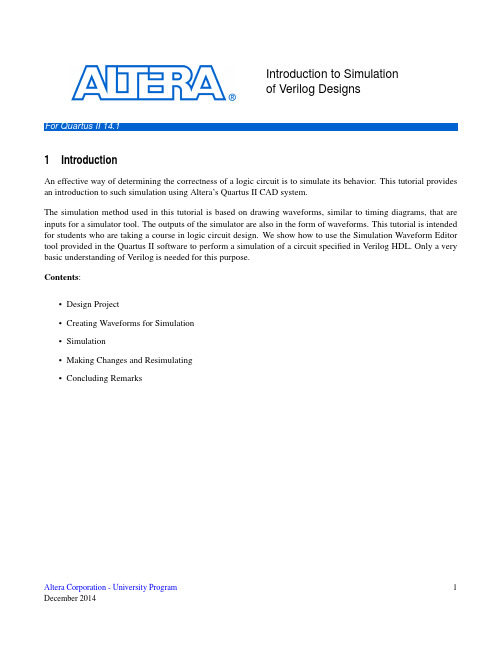
Introduction to Simulationof Verilog DesignsII14.11IntroductionAn effective way of determining the correctness of a logic circuit is to simulate its behavior.This tutorial provides an introduction to such simulation using Altera’s Quartus II CAD system.The simulation method used in this tutorial is based on drawing waveforms,similar to timing diagrams,that are inputs for a simulator tool.The outputs of the simulator are also in the form of waveforms.This tutorial is intended for students who are taking a course in logic circuit design.We show how to use the Simulation Waveform Editor tool provided in the Quartus II software to perform a simulation of a circuit specified in Verilog HDL.Only a very basic understanding of Verilog is needed for this purpose.Contents:•Design Project•Creating Waveforms for Simulation•Simulation•Making Changes and Resimulating•Concluding Remarks1 Altera Corporation-University ProgramDecember2014The Simulation Waveform Editor tool is available for use with Altera’s Quartus II software version13.0or later.It allows the user to apply inputs to the designed circuit,usually referred to as test vectors,in the form of waveforms and to observe the outputs generated in response.In this tutorial,the reader will learn about:•Test vectors needed to test the designed circuit•Using the Simulation Waveform Editor tool to draw test vector waveforms•Functional simulation,which is used to verify the functional correctness of a synthesized circuit•Timing simulation,which is used to verify the timing of signals in a synthesized circuitThis tutorial is aimed at the reader who wishes to simulate circuits defined by using the Verilog hardware description language.An equivalent tutorial is available for the user who prefers the VHDL language.2Design ProjectTo illustrate the simulation process,we will use a very simple logic circuit that implements the majority function of three inputs,x1,x2and x3.The circuit is defined by the expressionf(x1,x2,x3)=x1x2+x1x3+x2x3In Verilog,this circuit can be specified as follows:module majority3(x1,x2,x3,f);input x1,x2,x3;output f;assign f=(x1&x2)|(x1&x3)|(x2&x3);endmoduleThe desired circuit has to be implemented in a Quartus II project.To do so,create a new directory(folder)for the Quartus II project;in this tutorial we call the folder simulation_intro.Enter the Verilog code for the majority3module into afile called majority3.v in the project directory.Then,create a Quartus II project and call it majority3.For the project choose as the target device any FPGA chip of your choosing;for example,select the EP4CE115F29C7, which is the device on the Altera DE2-115board,or the5CSEMA5F31C6,which is the device on the DE1-SoC board.2Altera Corporation-University ProgramDecember20143Creating Waveforms for SimulationTo create test vectors for your design,select File>New...>Verification/Debugging Files>University Program VWF in the Quartus II window where the design project is open.This opens the Simulation Waveform Editor tool, shown in Figure1,which allows you to specify the desired input waveforms.Figure1.The Waveform Editor window.For our simple circuit,we can do a complete simulation by applying all eight possible valuations of the input signals x1,x2and x3.The output f should then display the logic values defined by the truth table for the majority function.We will run the simulation for800ns;so,select Edit>Set End Time...in the Waveform Editor and in the pop-up window that will appear specify the time of800ns,and click OK.This will adjust the time scale in the window of Figure1.Before drawing the input waveforms,it is necessary to locate the desired signals in the implemented circuit.In FPGA jargon,the term“node”is used to refer to a signal in a circuit.This could be an input signal(input node), output signal(output node),or an internal signal.For our task,we need tofind the input and output nodes.This is done by using a utility program called the Node Finder.In the Waveform Editor window,select Edit>Insert>Insert Node or Bus....In the pop-up window that appears, which is shown in Figure2,click on Node Finder.3 Altera Corporation-University ProgramDecember2014Figure2.The Insert Node or Bus dialog.The Node Finder window is presented in Figure3.Afilter is used to identify the nodes of interest.In our circuit, we are only interested in the nodes that appear on the pins(i.e.external connections)of the FPGA chip.Hence,the filter setting should be Pins:all.Click on List,which will display the nodes as indicated in thefigure.In a large circuit there could be many nodes displayed.We need to select the nodes that we wish to observe in the simulation. This is done by highlighting the desired nodes and clicking on the>button.Select the nodes labeled x1,x2,x3,and f,which will lead to the image in Figure4.Click OK in this window and also upon return to the window in Figure2. This returns to the Waveform Editor window,with the selected signals included as presented in Figure5.Figure3.The Node Finder dialog.4Altera Corporation-University ProgramDecember2014Figure4.The selected signals.Observe that in Figure5all input signals are at logic level0.The output,f is shown as undefined.Next,we have to draw the input waveforms.Then,we will simulate the circuit,which will produce the output waveform.To make it easier to draw the input waveforms,the Waveform Editor displays dashed grid lines.The spacing of the grid lines can be adjusted by selecting Edit>Grid Size...,and in the pop-up box in Figure6specifying the desired size.The spacing of grid lines in Figure5is20ns.Another convenience in drawing is to have transitions of a waveform snap on grid lines.This feature is activated by clicking on the Snap to Grid icon,or by selecting the command Edit>Snap to Grid.Figure5.Signals in the Waveform Editor window.Altera Corporation-University Program5 December2014Figure6.Specifying the grid spacing.Input waveforms can be drawn in different ways.The most straightforward way is to indicate a specific time range and specify the value of a signal.To illustrate this approach,click the mouse on the x1waveform near the400-ns point and then drag the mouse to the800-ns point.The selected time interval will be highlighted in blue,as depicted in Figure7.Change the value of the waveform to1by clicking on the Forcing High(1)icon,as illustrated in Figure8.Figure7.Selection of a time interval.6Altera Corporation-University ProgramDecember2014Figure8.Drawing the waveform for x1In creating the waveform for x1,we used the icon to implement the logic value1.Another possibility is to invert the value of the signal in a selected time interval by using the Invert icon.We will use this approach to create the waveform for x2,which should change from0to1at200ns,then back to0at400ns,and again to1at600ns. Select the interval from200to400ns and click on the icon.Then do the same for the interval from600to800ns, as illustrated in Figure9.Figure9.Drawing the waveform for x2.We will use a third approach to draw the waveform for x3.This signal should alternate between logic values0and 1at each100-ns interval.Such a regular pattern is indicative of a clock signal that is used in many logic circuits. Even though there is no clock signal in our example circuit,it is convenient to specify x3in this manner.Click on the x3input,which selects the entire800-ns interval.Then,click on the Overwrite Clock icon,as indicated in Figure10.This leads to the pop-up window in Figure11.Specify the clock period of200ns and the duty cycle of7 Altera Corporation-University ProgramDecember201450%,and click OK.The result is depicted in Figure12.Figure10.Drawing the waveform for x3.Figure11.Defining the clock characteristics8Altera Corporation-University ProgramDecember2014Figure12.The completed input waveforms.Save the waveformfile using a suitable name;we chose the name majority3.vwf.Note that the suffix vwf stands for vector waveformfile.VWFfiles that are added to the Quartus II project can be accessed at any time in the Project Navigator Widget’s Files tab.4SimulationThe Simulation Waveform Editor performs the simulation by using the simulation tool known as ModelSim.ModelSim-Altera Edition is strongly recommended for use with the Simulation Waveform Editor,as it contains the Altera de-vice libraries necessary for simulations.To use a standard version of ModelSim,the path to its executables must be specified in the Quartus II software under Tools>Options...>EDA T ool Options.If both ModelSim and ModelSim-Altera are available,the simulator will preferentially use ModelSim-Altera.4.1Functional SimulationNow that we have created the input vector waveform,we can simulate the circuit.In the Simulation WaveformEditor,select Simulation>Run Functional Simulation,or click on the icon.A pop-up window will show the progress of the simulation,then automatically close when it is complete.A second Simulation Waveform Ed-itor window then opens the output waveform,as depicted in Figure13.The output waveform is read-only,so any changes in simulation have to be done by modifying the majority3.vwffile and resimulating the circuit.Observe that the output f is equal to1whenever two or three inputs have the value1,which verifies the correctness of our design.9 Altera Corporation-University ProgramDecember2014Figure13.Result of the functional simulation.4.2Timing SimulationTo observe the actual propogation delays in our circuit,we have to perform a timing simulation.(Note that for FPGA devices with preliminary timing models that the timing simulation results may be the same as functional simulation results.)In the Simulation Waveform Editor,select Simulation>Run Timing Simulation,or click on the icon.A pop-up window will show the progress of the simulation,then automatically close when it is complete.A second Simulation Waveform Editor window then opens the output waveform.The output waveform is read-only,so any changes in simulation have to be done by modifying the majority3.vwffile and resimulating the circuit.The timing simulation shows that there are delays when signals change from one value to another.Figure14shows the waveform,zoomed in at300ns to show the propogation delay between x3and f.The waveform indicates that the maximum delay is approximately6ns.10Altera Corporation-University ProgramDecember2014Figure14.Result of the timing simulation,zoomed in at300ns.5Making Changes and ResimulatingChanges in the input waveforms can be made using the approaches explained above.The circuit can then be resimu-lated using the altered waveforms.For example,change the waveform for x1to have the logic value1in the interval from100to240ns,as indicated in Figure15.Now,simulate the circuit again.The result is given in Figure16.If errors in the circuit are discovered,then these errors can befixed by changing the Verilog code and recompiling the design using the Quartus II software.Figure15.Modified input waveforms.Figure16.Result of the new simulation.6Concluding RemarksThe purpose of this tutorial is to provide a quick introduction to the Simulation Waveform Editor,explaining only the rudimentary aspects of functional and timing simulations.Details about additional features of the Simulation Waveform Editor can be found in the appendix of this document.To learn about more about simulating circuits using ModelSim,please refer to the tutorials Introduction to Model-Sim’s Graphical Waveform Editor,and Using ModelSim to Simulate Logic Circuits,which are available on Altera’s University Program website.12Altera Corporation-University ProgramA Simulation Waveform EditorIn section3we introduced the Waveform Editor tool,which is used to view and edit waveforms that are used in simulation.Additional features of the Waveform Editor are described in this appendix.A.1Waveform Editor ToolbarThe Waveform Editor window is illustrated in Figure1.The tool includes several commands which can be accessed by using the mouse,including File,Edit,View,Simulation,and Help.Below these commands,as shown in the figure,there is a toolbar that contains a number of icons which are useful when manipulating waveforms.This toolbar should be visible by default,but if it is not visible,then right-click near the top of the window(below the title bar)and select Waveform Editor in the menu that appears.The toolbar icons are described below.Selection T oolThis tool is used to select waveform intervals and apply changes.To make a selection,click on any part of a waveform and drag the blue box across the desired interval.It’s possible to select multiple waveforms at the same time,as shown in Figure1,or select entire waveform(s)by clicking on its name(s).ing the Selection Tool to select a portion of multiple waveforms.Double clicking the selection tool anywhere on a waveform will select the largest interval with the same value from where the cursor points.Double clicking on a selected interval brings up the window to set arbitrary values for that interval.Zoom T oolThis tool is used to zoom in or zoom out in the waveform display,as indicated in Figure2.Left-clicking zooms into the display and right-clicking zooms out.ing the Zoom Tool.Forcing Unknown(X)This tool allows the selected part of a waveform to be set to the value Unknown(x).An example is given in Figure3,using the majority3function circuit that was described in section2.The value of the signal x3has been set to unknown for thefirst half of the simulation.Running the simulation with these input values results in the output waveform f that is shown in thefigure.Note that the value of f is unknown between200to400 ns.Figure3.Setting the value of an input to Unknown(X).Forcing Low(0)and Forcing High(1)These tools are used to force the selected part of a waveform to the value low(0)or high(1),as shown in Figures4and5,respectively.14Altera Corporation-University ProgramFigure4.Forcing x1to be low from0to400ns.Figure5.Forcing x1to be high from400to800ns.High Impedance(Z)This tool forces the selected waveform to the value High Impedance(Z),as shown in Figure6.The high impedance value represents a signal that has not been set to any specific value—that is,an input pin that is not connected.Forcing output waveforms to have high impedance does not affect the output simulation waveforms.Figure6.Setting a signal to high impedance.Weak Low(L)and Weak High(H)These tools are used to set a signal to the values Weak Low(L)or Weak High(H),which represents a circuit in which a bidirectional signal is pulled down or up by using a resistor.Examples are shown in Figures7and 8.Figure7.Changing the x1signal to be weak low from200to400ns.16Altera Corporation-University ProgramFigure8.Changing the x1signal to be weak high from400to600ns.InvertThis tool inverts the value of a selected waveform,as shown in Figure9.Low signals become high,weak low signals become weak high,and vice versa for both cases.The Invert tool has no effect on a signal that is set to high impedance or unknown.Figure9.Inverting the x1signal from100to260ns.Count ValueThis tool allows a waveform to be partitioned into sections,in which the value is incremented by a specified amount.The Count Value tool can only be applied to a single waveform or a grouped waveform(see sectionB.1).The options that are available when using the Count T ool are illustrated in Figure10.Figure10.Options available for for the Count Value tool.As an example,Figure11shows the3-bit input signal called count set to increment by one every100ns.Figure11.An example of using the Count Value tool.Overwrite ClockThis tool is used to generate a periodic waveform,which is often used as a clock signal.The options available when using the Overwrite Clock tool are shown in Figure12.18Altera Corporation-University ProgramFigure12.Options available for the Overwrite Clock tool.In the example of Figure13,the x3signal has been generated with a period of200ns,an offset of0ns,and a duty cycle of50%.Figure13.An exmaple of using the Overwrite Clock tool.Arbitrary ValueThis tool allows a signal to be set to an arbitrary value,which is particularly useful for specifying the value ofa multibit waveform.The options available when using the Arbitrary Value tool are shown in Figure14.Figure14.Options available for for the Arbitrary Value tool.As an example,in Figure15the count signal is set to three different arbitrary binary values as specified by theuser.Figure15.The Arbitrary Value tool is used to set values for the count signal.Random ValuesThis tool assigns random values to the selected waveform(s),with several options as shown in Figure16.Figure16.Various options available for the Random Value tool.For example,in Figure17,the signal x1has been given random values.20Altera Corporation-University ProgramFigure17.An example of the Random Value tool being used.Snap to GridThis option allows selections made with the Selection T ool to snap to the light grey grid lines running verti-cally down the waveform display.This option can be toggled on and off by pressing the Snap to Grid button.It is set to on by default.Figure18shows an example of the Selection Tool being used with the Snap to Grid option turned off.Figure18.An example of the Snap to Grid option turned off.Snap to T ransitionThis option allows the Selection Tool to automatically extend a selection to thefirst transition encountered on both sides of the selection of one or more waveforms.For example,with the Snap to T ransition option turned on,the Selection Tool rectangle shown in Figure19would be expanded to create the selections illustrated in Figure20.This option can be toggled on and off by pressing the Snap to T ransition button,and is set to off by default.Figure19.Making a selection with the Snap to T ransition option enabled.Figure20.The expanded selection resulting from Figure19.B Using Multibit SignalsThis section describes features of the Simulation Waveform Editor that are useful for dealing with multibit signals.B.1Grouping and Ungrouping SignalsIndividual signals can be grouped together to create a multibit waveform.This is done byfirst selecting the desired waveforms by clicking on their names in the leftside of the Waveform Editor with the key Ctrl pressed as indicated in Figure21.Then,as shown in thefigure,the grouping of signals is done by right-clicking on the selection and choosing Grouping>Group....22Altera Corporation-University ProgramFigure21.An example of grouping signals.In the options dialogue that opens,illustrated in Figure22,a name must be assigned to the group,as well as a radix.In the example shown,the name count has been chosen with a binary radix.The resulting group of signals is shown in Figure23.The multibit waveform can be expanded in the waveformeditor to display its individual signals.Figure23.An example of expanding a multibit signal.A multibit signal can be ungrouped by right-clicking on the group of signals and selecting Grouping>Ungroup.... It is also possible to create hierarchical groupings of signals as illustrated in Figure24.In this example,the two bit signal called level2is combined with the signal called x3to create the three bit signal called level1.It is only possible to group and ungroup top-level signals.Figure24.An example of hierarchical groups.It is also possible to group input and output signals,as shown in Figure25.24Altera Corporation-University ProgramFigure25.An example of grouping input and output signals.B.2Reverse Group or Bus Bit OrderIn Figure23,the three bit signal count is displayed as the3-tuple x1x2x3.It is possible to reverse the order in which the bits are displayed as illustrated in Figure26.This is done by right-clicking on the name of the multibit signal and selecting Reverse Group or Bus Bit Order,as seen in thefigure.Figure26.Reversing the bit order on a group of signals.The effects of the bit reversal can be seen in Figure27.The count waveform is now displayed as the3-tuple x3x2x1.Figure27.The result of reversing the bit order in Figure26.Copyright©2014Altera Corporation.26Altera Corporation-University Program。

.SNNOISERuns periodic AC noise analysis on nonautonomous circuits in a large-signal periodic steady state..SNNOISE output insrc frequency_sweep [N1, +/-1]+ [LISTFREQ=(freq1 [freq2 ... freqN ]|none|all]) [LISTCOUNT=num ]+ [LISTFLOOR=val ] [LISTSOURCES=on|off].HBAC / .SNACRuns periodic AC analysis on circuits operating in a large-signal periodic steady state..HBAC frequency_sweep .SNAC frequency_sweep.HBXF / .SNXFCalculates transfer function from the given source in the circuit to the designated output..HBXF out_var frequency_sweep .SNXF out_var frequency_sweep.PTDNOISECalculates the noise spectrum and total noise at a point in time..PTDNOISE output TIME=[val |meas |sweep ] +[TDELTA=time_delta ] frequency_sweep+[listfreq=(freq1 [freq2 ... freqN ]|none|all)] [listcount=num ]+[listfloor=val ] [listsources=on|off]RF OptionsSIM_ACCURACY=x Sets and modifies the size of the time steps. The higher the value, thegreater the accuracy; the lower the value, the faster the simulation runtime. Default is 1.TRANFORHB=n 1 Forces HB analysis to recognize or ignore specific V/I sources, 0 (default) ignores transient descriptions of V/I sources.HBCONTINUE=n Specifies whether to use the sweep solution from the previous simulation as the initial guess for the present simulation. 0 restarts each simulation in a sweep from the DC solution, 1 (default) uses the previous sweep solution as the initial guess.HBSOLVER=n Specifies a preconditioner for solving nonlinear circuits. 0 invokes the direct solver. 1 (default) invokes the- matrix-free Krylov solver. 2 invokes the two-level hybrid time-frequency domain solver.SNACCURACY=n Sets and modifies the size of the time steps. The higher the value, the greater the accuracy; the lower the value, the faster the simulation runtime. Default is 10.SAVESNINIT=”filename ” Saves the operating point at the end of SN initialization.LOADSNINIT=”filename ” Loads the operating point saved at end of SN initialization.Output Commands.BIASCHK .MEASURE .PRINT .PROBEFor details about all commands and options, see the HSPICE ® Reference Manual: Commands and Control Options.Synopsys Technical Publications 690 East Middlefield Road Mountain View, CA 94043Phone (650) 584-5000 or (800) Copyright ©2017 Synopsys, Inc. All rights reserved.Signal Integrity Commands.LINCalculates linear transfer and noise parameters for a general multi-port network..LIN [sparcalc [=1|0]] [modelname=modelname ] [filename=filename ]+ [format=selem|citi|touchstone|touchstone2] [noisecalc [=1|0]]+ [gdcalc [=1|0]] [dataformat=ri|ma|db]+ [listfreq=(freq1 [freq2 ... freqN ]|none|all)] [listcount=num ]+ [listfloor=val ] [listsources=1|0|yes|no].STATEYEPerforms Statistical Eye Diagram analysis..STATEYE T=time_interval Trf=rise_fall_time [Tr=rise_time ] + [Tf=fall_time ] Incident_port=idx1[, idx2, … idxN ]+ Probe_port=idx1[, idx2, … idxN ] [Tran_init=n_periods ] + [V_low=val ] [V_high=val ] [TD_In=val ] [TD_PROBE=val ]+ [T_resolution=n ] [V_resolution=n ] [VD_range=val ]+ [EDGE=1|2|4|8] [MAX_PATTERN=n ] [PATTERN_REPEAT=n ] + [SAVE_TR=ascii] [LOAD_TR=ascii] [SAVE_DIR=string ]+ [IGNORE_Bits=n ] [Tran_Bit_Seg=n ]+ [MODE=EDGE|CONV|TRAN] [XTALK_TYPE = SYNC|ASYNC|DDP|NO|ONLY]+ [Unfold_Length=n ] [TXJITTER_MODE = 1|2]RF Analysis Commands.ACPHASENOISEHelps interpret signal and noise quantities as phase variables for accumulated jitter for closed-loop PLL analysis..ACPHASENOISE output input [interval ] carrier=freq+ [listfreq=(freq1 [freq2 ... freqN ]|none|all)][listcount=num ]+ [listfloor=val ] [listsources=1|0].HBRuns periodic steady state analysis with the single and multitone Harmonic Balance algorithm..HB TONES=F1[,F2,…,FN ] [SUBHARMS=SH ] [NHARMS=H1[,H2,…,HN ]]+ [INTMODMAX=n ] [SWEEP parameter_sweep ].SNRuns periodic steady state analysis using the Shooting Newton algorithm..SN TRES=Tr PERIOD=T [TRINIT=Ti ] [MAXTRINITCYCLES=integer ]+ [SWEEP parameter_sweep ] [NUMPEROUT=val ].SN TONE=F1 [TRINIT=Ti ] NHARMS=N [MAXTRINITCYCLES=integer ]+ [NUMPEROUT=val ] [SWEEP parameter_sweep ].HBOSC / .SNOSCPerforms analysis on autonomous oscillator circuits..HBOSC TONE=F1 NHARMS=H1+ PROBENODE=N1,N2,VP [FSPTS=NUM,MIN,MA X]+ [SWEEP parameter_sweep ] [SUBHARMS=I ] [STABILITY=-2|-1|0|1|2].SNOSC TONE=F1 NHARMS=H1 [TRINIT=Ti ]+ [OSCTONE=N ] [MAXTRINITCYCLES=N ]+ [SWEEP parameter_sweep ].PHASENOISEInterprets signal / noise quantities as phase variables for accumulated jitter in closed-loop PLL analysis..PHASENOISE output frequency_sweep [method= 0|1|2]+ [listfreq=(freq1 [freq2 ... freqN ]|none|all)] [listcount=num ]+ [listfloor=val ] [listsources=1|0] [carrierindex=int ].HBNOISEPerforms cyclo-stationary noise analysis on circuits in a large-signal periodic steady state..HBNOISE output insrc parameter_sweep [N1, N2, ..., NK ,+/-1]+ [LISTFREQ=(freq1 [freq2 ... freqN ]|none|all]) [LISTCOUNT=num ]+ [LISTFLOOR=val ] [LISTSOURCES=on|off].NOISERuns noise analysis in frequency domain..NOISE v(out ) vin [interval ] [listckt[=1|0]]+ [listfreq=freq1 [freq2 ... freqN ]|none|all]) [listcount=num ]+ [listfloor=val ] [listsources=1|0|yes|no]] [listtype=1|0].ALTERReruns a simulation using different parameters and data from a specified sequence or block. The .ALTER block can contain element commands and .AC, .ALIAS, .DATA, .DC, .DEL LIB, .HDL, .IC (initial condition), .INCLUDE, .LIB, .MODEL, .NODESET, .OP, .OPTION, .PARAM, .TEMP, .TF, .TRAN, and .VARIATION commands..ALTER title_string.DCPerforms DC analyses..DC var1 START=start1 STOP=stop1 STEP=incr1Parameterized Sweep.DC var1 start1 stop1 incr1 [SWEEP var2 type np start2 stop2].DC var1 START=[par_expr1] STOP=[par_expr2] STEP=[par_expr3]Data-Driven Sweep.DC var1 type np start1 stop1 [SWEEP DATA=datanm (Nums )].DC DATA=datanm [SWEEP var2 start2 stop2 incr2].DC DATA=datanm (Nums )Monte Carlo Analysis.DC var1 start1 stop1 incr1 [SWEEP MONTE=MCcommand ].DC MONTE=MCcommand.OPCalculates the operating point of the circuit..OP format_time format_time ... [interpolation].PARAMDefines parameters. Parameters are names that have associated numeric values or functions..PARAM ParamName = RealNumber | ‘AlgebraicExpression’ | DistributionFunction (Arguments ) | str(‘string’) | OPT xxx (initial_guess, low_limit, upper_limit )Monte Carlo Analysis.PARAM mcVar = UNIF(nominal_val , rel_variation [, multiplier ]) | AUNIF(nominal_val , abs_variation [, multiplier ])| GAUSS(nominal_val , rel_variation , num_sigmas [, multiplier ]) | AGAUSS(nominal_val , abs_variation , num_sigmas [, multiplier ]) | LIMIT(nominal_val , abs_variation ).STOREStarts creation of checkpoint files describing a running process during transient analysis..STORE [file=checkpoint_file ] [time=time1]+ [repeat=checkpoint_interval ].TEMPPerforms temperature analysis at specified temperatures..TEMP t1 [t2 t3 ...].TRANPerforms a transient analysis.Single-Point Analysis.TRAN tstep1 tstop1 [START=val ] [UIC]Multipoint Analysis.TRAN tstep1 tstop1 [tstep2 tstop2 ... tstepN tstopN ]+ RUNLVL =(time1 runlvl1 time2 runlvl2...timeN runlvlN )+ [START=val ] [UIC] [SWEEP var type np pstart pstop ]Monte Carlo Analysis.TRAN tstep1 tstop1 [tstep2 tstop2 ... tstepN tstopN ]+ [START=val ] [UIC] [SWEEP MONTE=MCcommand ]Invoking HSPICESimulation Modehspice [-i] input_file [-o [output_file ]] [-hpp] [-mt #num ][-gz] [-d] [-case][-hdl filename ] [-hdlpath pathname ] [-vamodel name ]Distributed-Processing Modehspice [-i] input_file [-o [output_file ]] -dp [#num ][-dpconfig [dp_configuration_file ]] [-dplocation [NFS|TMP][-merge]Measurement Modehspice -meas measure_file -i wavefile -o [output_file ]Help Modehspice [-h] [-doc] [-help] [-v]Argument Descriptions-i input_file Specifies the input netlist file name.-o output_file Name of the output file. HSPICE appends the extension .lis.-hpp Invokes HSPICE Precision Parallel.-mt #num Invokes multithreading and specifies the number of processors. Works best when -hpp is used.-gz Generates compression output on analysis results for these output types: .tr#, .ac#, .sw#, .ma#, .mt#, .ms#, .mc#, and .print*.-d (UNIX) Displays the content of .st0 files on screen while running HSPICE.-case Enable case sensitivity.-hdl filename Specifies a Verilog-A file.-hdlpath pathname Specifies the search path for Verilog-A files.-vamodel name Specifies the cell name for Verilog-A definitions.-dp #num -dpconfig dpconfig_file -dplocation [NFS|TMP] Invokesdistributed processing and specifies number of processes, the configuration file for DP, and the location of the output files.-merge Merge the output files in the distributed-processing mode.-meas measure_file Calculates new measurements from a previous simulation.-h Outputs the command line help message.-doc Opens the PDF documentation set for HSPICE (requires Adobe Acrobat Reader or other PDF document reader).-help Invokes the online help system (requires a Web browser).-v Outputs HSPICE version information.HSPICE is fully integrated with the Synopsys® Custom Compiler™ Simulation and Analysis Environment (SAE). See the Custom Compiler™ Simulation and Analysis Environment User Guide .To use the HSPICE integration to the Cadence® Virtuoso® Analog Design Environment, go to /$INSTALLDIR/interface/ and follow the README instructions.Analysis Commands.ACPerforms AC analyses.Single / Double Sweep.AC type np fstart fstop.AC type np fstart fstop [SWEEP var+ [START=]start [STOP=]stop [STEP=]incr ].AC type np fstart fstop [SWEEP var type np start stop ]Sweep Using Parameters.AC type np fstart fstop [SWEEP DATA=datanm (Nums )].AC DATA=datanm.AC DATA=datanm [SWEEP var [START=]start [STOP=]stop [STEP=]incr ].AC DATA=datanm [SWEEP var type np start stop ]Monte Carlo Analysis.AC type np fstart fstop [SWEEP MONTE=MCcommand ].LSTBInvokes loop stability analysis..LSTB [lstbname ] mode=[single|diff|comm + vsource=[vlstb |vlstbp,vlstbn ]Data-Driven Sweep.TRAN DATA=datanm.TRAN DATA=datanm [SWEEP var type np pstart pstop ].TRAN tstep1 tstop1 [tstep2 tstop2 ... tstepN tstopN ]+ [START=val ] [UIC] [SWEEP DATA=datanm (Nums )]Time Window-based Speed/Accuracy Tuning by RUNLVL.TRAN tstep tstop [RUNLVL=(time1 runlvl1...timeN runlvlN )]Circuit Block-based Speed/Accuracy Tuning by RUNLVL.TRAN tstep tstop+ [INST=inst_exp1 RUNLVL=(time11 runlvl11...time1N runlvl1N )]+ [SUBCKT=subckt_exp2 RUNLVL=(time21 runlvl21...time2N runlvl2N )]Time Window-based Temperature Setting.TRAN tstep tstop [tempvec=(t1 Temp1 t2 Temp2 t3 Temp3...)+[tempstep=val ]].TRANNOISEActivates transient noise analysis to compute the additional noise variables over a standard .TRAN analysis..TRANNOISE output [METHOD=MC] [SEED=val ] [SAMPLES=val ] [START=x ]+ [AUTOCORRELATION=0|1|off|on] [FMIN=val ] [FMAX=val ] [SCALE=val ]+ [PHASENOISE=0|1|2] [JITTER=0|1|2] [REF=srcName ] [PSD=0|1]HSPICE Options.OPTION opt1 [opt2 opt3 …]opt1 opt2 … Specify input control options.General OptionsALTCC=n Enables reading the input netlist once for multiple .ALTER statements. Default is 0.LIS_NEW=x Enables streamlining improvements to the *.lis file. Default is 0. SCALE=x Sets the element scaling factor. Default is 1.POSTTOP=n Outputs instances up to n levels deep. Default is 0.POSTLVL=n Limits data written to the waveform file to the level of nodes specified by n .POST=n Saves results for viewing by an interactive waveform viewer. Default is 0.PROBE=n Limits post-analysis output to only variables specified in .PROBE and .PRINTstatements. Default is 0.RC Reduction OptionsSIM_LA=name Starts linear matrix (RC) reduction to the PACT, PI, or LNE algorithm. Defaultis off.Transient OptionsAUTOSTOP=n Stops transient analysis after calculating all TRIG-TARG, FIND-WHEN, andFROM-TO measure functions. Default is 0.METHOD=name Sets numerical integration method for a transient analysis to GEAR, or TRAP(default), or BDF.RUNLVL=n Controls the speed and accuracy trade-off; where n can be 1 through 6. The higher the value, the greater the accuracy; the lower the value, the faster the simulation runtime. Default is 3.Variability and Monte Carlo Analysis.AC .DC .TRAN .MEASURE .MODEL .PARAM .ACMATCHCalculates the effects of variations on the AC transfer function, with one or more outputs..ACMatch Vm(n1) Vp(n1) Vr(n1) Vi(n1) Vm(n1,n2) Im(Vmeas ).DCMATCHCalculates the effects of variations on the DC operating point, with one or more outputs..DCMatch V(n1) V(n1,n2) I(Vmeas )。

英语作文-集成电路设计师需要了解的基础知识与技术要点Integrated Circuit (IC) Designers are professionals responsible for creating and developing the complex electronic circuits found in various electronic devices. To excel in this field, a deep understanding of fundamental knowledge and technical skills is essential. This article aims to provide an overview of the basic knowledge and technical points that IC Designers need to be familiar with.1. Solid Foundation in Electronics:IC Designers must have a solid foundation in electronics, including knowledge of electronic components, circuit theory, and digital logic. They should understand the behavior of different electronic components such as resistors, capacitors, and transistors, and be able to analyze and design basic electronic circuits.2. Semiconductor Physics:Understanding semiconductor physics is crucial for IC Designers. They should be familiar with concepts such as energy bands, carrier concentration, doping, and junctions. Additionally, knowledge of the different semiconductor materials, such as silicon and gallium arsenide, is necessary for designing efficient and reliable integrated circuits.3. Digital Design:IC Designers must have a strong grasp of digital design principles. This includes understanding Boolean algebra, logic gates, flip-flops, and sequential and combinational circuits. They should be able to design and optimize digital circuits using hardware description languages (HDLs) like Verilog or VHDL.4. Analog Design:Analog design is another essential skill for IC Designers. They should be knowledgeable about operational amplifiers, filters, oscillators, and analog-to-digital anddigital-to-analog converters. Proficiency in simulation tools like SPICE (Simulation Program with Integrated Circuit Emphasis) is necessary to analyze and verify the performance of analog circuits.5. Circuit Simulation and Analysis:IC Designers need to be proficient in using circuit simulation tools to verify the functionality and performance of their designs. They should be able to simulate circuits, analyze their behavior, and optimize their performance. Tools like Cadence Virtuoso, Synopsys HSPICE, and Mentor Graphics are commonly used for circuit simulation and analysis.6. Layout Design:Layout design involves the physical placement and routing of transistors, interconnects, and other components on an integrated circuit. IC Designers should be skilled in using layout design tools like Cadence Virtuoso Layout Editor or Mentor Graphics Calibre to create compact and efficient layouts that meet the design specifications and performance requirements.7. Design for Manufacturability (DFM):IC Designers should be aware of Design for Manufacturability principles to ensure that their designs can be manufactured reliably and cost-effectively. They need to consider factors such as process variations, yield optimization, and design rules compliance during the design phase.8. Low Power Design Techniques:With the increasing demand for portable and energy-efficient devices, IC Designers should be familiar with low power design techniques. This includes power management, clock gating, voltage scaling, and optimizing power consumption at both the circuit and system level.9. Signal Integrity and Timing Analysis:IC Designers need to ensure that their designs meet the required signal integrity and timing specifications. They should be skilled in performing signal integrity analysis to minimize noise, crosstalk, and reflections. Timing analysis is also crucial to ensure that the circuit operates within the desired timing constraints.10. Design Verification and Testing:IC Designers should have knowledge of design verification and testing techniques to ensure the correctness and reliability of their designs. This includes functional verification, test pattern generation, and fault simulation. They should be able to perform thorough testing to detect and fix any design flaws or defects.In conclusion, becoming a successful IC Designer requires a strong foundation in electronics, semiconductor physics, digital and analog design, circuit simulation, layout design, DFM, low power design, signal integrity, timing analysis, and design verification. By mastering these fundamental knowledge areas and technical skills, IC Designers can create innovative and efficient integrated circuits that power the ever-advancing world of technology.。

目录摘要 IAbstract II1 引言 11.1 课题研究的背景 11.2 课题研究的国内外现状 12 短路故障分析 12.1 近年来短路故障 12.2 短路的定义及其分类 22.3 短路故障产生的原因及危害 42.4 预防措施 42.5 短路故障的分析诊断方法 53 仿真与建模 63.1 仿真工具简介 63.1.1 MATLAB的特点 63.1.2 Simulink简介 73.1.3 SPS(SimPowerSystems) 83.1.4 GUI(图形用户界面) 83.2 模型的建立 83.2.1 无限大电源系统短路故障仿真模型 83.2.2 仿真参数的设置 94 仿真结果分析 164.1 三相短路分析 164.2 单相短路分析(以A相短路为例) 18 4.3 两相短路(以A、B相短路为例) 224.4 两相接地短路(以A、B相短路为例) 255 结论 286 前景与展望 28参考文献 29致谢 30ContentsAbstract II1 Introduction 11.1 Project background to the study 11.2 The research situation at home and abroad 12 Analysis of short-circuit fault 12.1 Short-circuit fault in recent years 12.2 Definition and classification of short-circuit fault 2 2.3 Causes and damage of short-circuit fault 42.4 Precautionary measures 42.5 Method to analysis and diagnosis of short-circuit fault 53 Simulation and modeling 63.1 Introduction to simulation tools 63.1.1 Features of MATLAB 63.1.2 Introduction to simulink 73.1.3 SPS(SimPowerSystems) 83.1.4 GUI(Graphical User Interfaces) 83.2 Establishment of the model 83.2.1 Infinite power system short-circuit fault simulation model 83.2.2 Simulation parameter settings 94 Simulation analysis 164.1 Analysis of three-phase short-circuit 164.2 Analysis of single-phase short circuit 184.3 Analysis of two-phase short circuit 224.4 Analysis of two-phase short circuit to ground 255 Conclusions 286 Outlook and prospect 28References 29Acknowledgement 30基于MATLAB的电力系统短路故障分析与仿真刘继文(山东农业大学机械与电子工程学院泰安 271018)摘要:短路是电力系统中最容易发生的故障,每年因短路而引发的电气事故不计其数。
英语作文-探索集成电路设计中的数字电路与模拟电路技术The exploration of integrated circuit design is a journey through the intricate world of digital and analog circuit technologies. These two fundamental types of circuits are the building blocks of modern electronics, each with its unique characteristics and applications.Digital circuits are the backbone of computers and all sorts of digital devices. They operate using discrete signals to represent logical and numerical values. These circuits are designed using logic gates, flip-flops, and other digital components that create the framework for complex processing tasks. Digital circuits are characterized by their ability to maintain a clear distinction between high and low logic levels, which is crucial for the accurate processing of binary data.On the other hand, analog circuits deal with continuous signals that reflect the nuances and variations found in the real world. These circuits are essential for tasks that require a representation of varying quantities, such as temperature, speed, or sound. Analog circuit design often involves operational amplifiers, resistors, capacitors, and inductors to manipulate these continuous signals in various ways, such as amplification, filtering, and modulation.The distinction between digital and analog circuits is not just in their operation but also in their design methodologies. Digital circuit design is often associated with a structured approach, where logic synthesis and formal verification methods ensure the correctness of the design. In contrast, analog circuit design requires a more artistic touch, with designers relying on experience and intuition to achieve the desired performance, often iterating through simulations and prototypes.Despite their differences, digital and analog circuits often coexist within the same system, particularly in mixed-signal integrated circuits. These circuits harness the strengths of both worlds, allowing for sophisticated functionalities such as digital-to-analog conversion (DAC) and analog-to-digital conversion (ADC), which are vital for interfacing digital processors with the analog environment.The synergy between digital and analog circuit technologies has paved the way for advancements in various fields, from telecommunications to medical devices. For instance, in a smartphone, digital circuits manage the user interface and computational tasks, while analog circuits handle audio processing and signal reception.As technology progresses, the line between digital and analog circuits continues to blur, with innovations like digitally-assisted analog design and analog computation in digital domains. The integration of these technologies challenges designers to possess a deep understanding of both areas, fostering a new era of integrated circuit design that is more versatile and powerful than ever before.In conclusion, the exploration of digital and analog circuit technologies in integrated circuit design is a testament to the ingenuity and adaptability of engineers. It is a field that constantly evolves, driven by the endless pursuit of efficiency, precision, and functionality. As we delve deeper into the microscopic realms of silicon and beyond, the fusion of digital and analog circuits remains a cornerstone of innovation, shaping the future of technology in profound ways. 。
英语作文-如何进行集成电路设计中的模拟电路设计与验证The design and verification of analog circuits within integrated circuit (IC) design is a meticulous process that requires a deep understanding of both theoretical principles and practical considerations. Analog circuits are responsible for handling continuous signals, which represent real-world phenomena such as temperature, sound, and pressure. These circuits are essential components in a vast array of electronic devices, from simple amplifiers to complex signal processing systems.Designing Analog Circuits:。
The initial phase in designing an analog circuit involves defining the specifications and constraints of the circuit. This includes the operational range, power consumption, size limitations, and the intended application. Once these parameters are established, the next step is to select the appropriate components, such as resistors, capacitors, transistors, and operational amplifiers, based on their characteristics and how they interact with each other.Circuit simulation software plays a crucial role at this stage. It allows designers to model and simulate the behavior of the circuit under various conditions. This helps in identifying potential issues and optimizing the circuit's performance before any physical prototype is built. Tools like SPICE (Simulation Program with Integrated Circuit Emphasis) are widely used for this purpose.Verification of Analog Circuits:。
2053-15832D MATER 2D Materials2190-5738 3 BIOTECH 3 Biotech1619-45004OR-Q J OPER RES4OR-A Quarterly Journal of OperationsResearch管理科学0149-1423AAPG BULL AAPG BULLETIN 工程技术1550-7416AAPS J AAPS Journal 医学1530-9932AAPS PHARMSCITECH AAPS PHARMSCITECH 医学2330-5517AATCC J RES AATCC Journal of Research 1532-8813AATCC REV AATCC REVIEW工程技术0942-8925ABDOM IMAGING ABDOMINAL IMAGING医学0025-5858ABH MATH SEM HAMBUABHANDLUNGEN AUS DEM MATHEMATISCHENSEMINAR DER UNIVERSITAT HAMBURG数学1069-6563ACAD EMERG MED ACADEMIC EMERGENCY MEDICINE 医学1040-2446ACAD MED ACADEMIC MEDICINE 医学1876-2859ACAD PEDIATR Academic Pediatrics PEDIATRICS 1076-6332ACAD RADIOL ACADEMIC RADIOLOGY 医学0044-586X ACAROLOGIA ACAROLOGIA 0898-9621ACCOUNT RES Accountability in research MEDICAL ETHICS 0001-4842ACCOUNTS CHEM RES ACCOUNTS OF CHEMICAL RESEARCH 化学0949-1775ACCREDIT QUAL ASSU ACCREDITATION AND QUALITY ASSURANCE 工程技术0889-325X ACI MATER J ACI MATERIALS JOURNAL 工程技术0889-3241ACI STRUCT J ACI STRUCTURAL JOURNAL 工程技术0360-0300ACM COMPUT SURV ACM COMPUTING SURVEYS工程技术1550-4832ACM J EMERG TECH CACM Journal on Emerging Technologies inComputing Systems工程技术0146-4833ACM SIGCOMM COMP CACM SIGCOMM Computer Communication ReviewCOMPUTER SCIENCE,INFORMATION SYSTEMS 0362-1340ACM SIGPLAN NOTICE ACM SIGPLAN NOTICES工程技术1549-6325ACM T ALGORITHMS ACM Transactions on AlgorithmsCOMPUTERSCIENCE, THEORY & METHODS 1544-3558ACM T APPL PERCEPT ACM Transactions on Applied Perception工程技术1544-3566ACM T ARCHIT CODEACM Transactions on Architecture andCode Optimization工程技术1556-4665ACM T AUTON ADAP SACM Transactions on Autonomous andAdaptive Systems工程技术1946-6226ACM T COMPUT EDUC ACM Transactions on Computing Education1529-3785ACM T COMPUT LOG ACM Transactions on Computational Logic 工程技术0734-2071ACM T COMPUT SYST ACM TRANSACTIONS ON COMPUTER SYSTEMS工程技术ISSN 期刊名缩写期刊名全称类别1073-0516ACM T COMPUT-HUM I ACM Transactions on Computer-Human Interaction工程技术0362-5915ACM T DATABASE SYS ACM TRANSACTIONS ON DATABASE SYSTEMS工程技术1084-4309ACM T DES AUTOMATACM TRANSACTIONS ON DESIGN AUTOMATIONOF ELECTRONIC SYSTEMS工程技术1539-9087ACM T EMBED COMPUTACM Transactions on Embedded ComputingSystems工程技术0730-0301ACM T GRAPHIC ACM TRANSACTIONS ON GRAPHICS工程技术1046-8188ACM T INFORM SYST ACM TRANSACTIONS ON INFORMATION SYSTEMS 工程技术1094-9224ACM T INFORM SYSTACM Transactions on Information andSystem Security工程技术2157-6904ACM T INTEL SYST TACM Transactions on Intelligent Systems and Technology COMPUTERSCIENCE,ARTIFICIALINTELLIGENCE1533-5399ACM T INTERNET TEC ACM Transactions on Internet Technology 工程技术1556-4681ACM T KNOWL DISCOVACM Transactions on Knowledge Discovery from Data COMPUTERSCIENCE,INFORMATIONSYSTEMS0098-3500ACM T MATH SOFTWAR ACM TRANSACTIONS ON MATHEMATICALSOFTWARE工程技术1049-3301ACM T MODEL COMPUT ACM Transactions on Modeling andComputer Simulation工程技术1551-6857ACM T MULTIM COMPU ACM Transactions on MultimediaComputing Communications and Applications工程技术0164-0925ACM T PROGR LANG S ACM TRANSACTIONS ON PROGRAMMINGLANGUAGES AND SYSTEMS工程技术1936-7406ACM T RECONFIG TECACM transactions on reconfigurable technology and systems COMPUTERSCIENCE,HARDWARE &ARCHITECTURE1550-4859ACM T SENSOR NETWO ACM Transactions on Sensor Networks 工程技术1049-331XACM T SOFTW ENG ME ACM TRANSACTIONS ON SOFTWAREENGINEERING AND METHODOLOGY工程技术1553-3077ACM T STORAGE ACM transactions on storageCOMPUTER SCIENCE,HARDWARE &ARCHITECTURE1559-1131ACM T WEB ACM Transactions on the Web 工程技术1839-2571ACOUST AUST Acoustics Australia 1063-7710ACOUST PHYS+ACOUSTICAL PHYSICS 物理1944-8244ACS APPL MATER INT ACS Applied Materials & Interfaces 工程技术2373-9878ACS BIOMATER-SCI E ACS Biomaterials-Science & Engineering2155-5435ACS CATAL ACS catalysis CHEMISTRY,PHYSICAL 1554-8929ACS CHEM BIOLACS Chemical Biology生物1948-7193ACS CHEM NEUROSCI ACS Chemical Neuroscience BIOCHEMISTRY &MOLECULAR BIOLOGY 2156-8952ACS COMB SCIACS Combinatorial ScienceCHEMISTRY,APPLIED 2373-8227ACS INFECT DIS ACS Infectious Diseases 2161-1653ACS MACRO LETT ACS Macro Letters化学1948-5875ACS MED CHEM LETT ACS Medicinal Chemistry Letters CHEMISTRY,MEDICINAL 1936-0851ACS NANO ACS Nano工程技术2330-4022ACS PHOTONICSACS Photonics2168-0485ACS SUSTAIN CHEM E ACS Sustainable Chemistry & Engineering CHEMISTRY,MULTIDISCIPLINARY2161-5063ACS SYNTH BIOL ACS Synthetic Biology 生物1091-5397ACSMS HEALTH FIT J ACSMS HEALTH & FITNESS JOURNAL 医学1610-1928ACTA ACUST UNITED ACTA ACUSTICA UNITED WITH ACUSTICA 物理0001-5113ACTA ADRIAT ACTA ADRIATICA 生物0906-4702ACTA AGR SCAND A-A ACTA AGRICULTURAE SCANDINAVICA SECTIONA-ANIMAL SCIENCE农林科学0906-4710ACTA AGR SCAND B-S ACTA AGRICULTURAE SCANDINAVICA SECTIONB-SOIL AND PLANT SCIENCE农林科学0139-3006ACTA ALIMENT HUNG ACTA ALIMENTARIA 农林科学0044-5967ACTA AMAZON ACTA AMAZONICA 0001-5172ACTA ANAESTH SCAND ACTA ANAESTHESIOLOGICA SCANDINAVICA 医学0167-8019ACTA APPL MATH ACTA APPLICANDAE MATHEMATICAE 数学0065-1036ACTA ARITH ACTA ARITHMETICA 数学0094-5765ACTA ASTRONAUT ACTA ASTRONAUTICA 工程技术0001-5237ACTA ASTRONOM ACTA ASTRONOMICA 地学天文1672-9145ACTA BIOCH BIOPH S ACTA BIOCHIMICA ET BIOPHYSICA SINICA 生物0001-527X ACTA BIOCHIM POL ACTA BIOCHIMICA POLONICA 生物1509-409X ACTA BIOENG BIOMEC Acta of Bioengineering and Biomechanics BIOPHYSICS1726-569X ACTA BIOETHActa Bioethica医学0001-5296ACTA BIOL CRACOV BACTA BIOLOGICA CRACOVIENSIA SERIESBOTANICA生物0236-5383ACTA BIOL HUNG ACTA BIOLOGICA HUNGARICA 生物1742-7061ACTA BIOMATER Acta Biomaterialia工程技术0325-2957ACTA BIOQUIM CLIN Acta Bioquimica Clinica Latinoamericana0001-5342ACTA BIOTHEOR ACTA BIOTHEORETICA生物0102-3306ACTA BOT BRAS Acta Botanica Brasilica PLANT SCIENCES 0365-0588ACTA BOT CROAT Acta Botanica Croatica PLANT SCIENCES 1253-8078ACTA BOT GALLICA ACTA BOTANICA GALLICA生物0187-7151ACTA BOT MEX Acta Botanica Mexicana生物0001-5385ACTA CARDIOL ACTA CARDIOLOGICA 医学1011-6842ACTA CARDIOL SIN Acta Cardiologica Sinica 医学0583-6050ACTA CARSOLOGICA ACTA CARSOLOGICA 地学0567-7351ACTA CHIM SINICA ACTA CHIMICA SINICA 化学1318-0207ACTA CHIM SLOV ACTA CHIMICA SLOVENICA 化学0001-5458ACTA CHIR BELG ACTA CHIRURGICA BELGICA医学0001-5415ACTA CHIR ORTHOP TACTA CHIRURGIAE ORTHOPAEDICAE ETTRAUMATOLOGIAE CECHOSLOVACAORTHOPEDICS 1508-1109ACTA CHIROPTEROL ACTA CHIROPTEROLOGICA 生物1233-2356ACTA CHROMATOGR ACTA CHROMATOGRAPHICA 化学0102-8650ACTA CIR BRAS Acta Cirurgica Brasileira 医学1784-3286ACTA CLIN BELG ACTA CLINICA BELGICA 0353-9466ACTA CLIN CROAT Acta Clinica Croatica医学2053-2733ACTA CRYSTALLOGR AActa Crystallographica A-Foundation andAdvances2052-5206ACTA CRYSTALLOGR B Acta Crystallographica Section B-Structural Science Crystal Engineeringand Materials2053-2296ACTA CRYSTALLOGR CActa Crystallographica Section C-Structural Chemistry2059-7983ACTA CRYSTALLOGR DActa Crystallographica Section D-Structural Biology2053-230X ACTA CRYSTALLOGR FActa Crystallographica Section F-Structural Biology Communications1330-027X ACTA DERMATOVENER Acta Dermatovenerologica Croatica 医学0001-5555ACTA DERM-VENEREOL ACTA DERMATO-VENEREOLOGICA 医学0940-5429ACTA DIABETOL ACTA DIABETOLOGICA 医学1841-0987ACTA ENDOCRINOL-BU Acta Endocrinologica-Bucharest医学0374-1036ACTA ENT MUS NAT PActa Entomologica Musei NationalisPragaeENTOMOLOGY 0873-9749ACTA ETHOL ACTA ETHOLOGICA 生物0001-5644ACTA GASTRO-ENT BE ACTA GASTRO-ENTEROLOGICA BELGICA2213-5812ACTA GEOD GEOPHYS Acta Geodaetica et Geophysica GEOCHEMISTRY &GEOPHYSICS 1214-9705ACTA GEODYN GEOMAT Acta Geodynamica et Geomaterialia 地学1581-6613ACTA GEOGR SLOV Acta Geographica Slovenica-GeografskiZbornik地学0001-5709ACTA GEOL POLACTA GEOLOGICA POLONICA地学1000-9515ACTA GEOL SIN-ENGL ACTA GEOLOGICA SINICA-ENGLISH EDITION 地学1895-7455ACTA GEOPHYS Acta Geophysica 1861-1125ACTA GEOTECHActa GeotechnicaENGINEERING,GEOLOGICAL 1854-0171ACTA GEOTECH SLOV Acta Geotechnica Slovenica 地学0001-5792ACTA HAEMATOL-BASE ACTA HAEMATOLOGICA 医学1827-9635ACTA HERPETOLActa HerpetologicaZOOLOGY0065-1281ACTA HISTOCHEM ACTA HISTOCHEMICA 生物0044-5991ACTA HISTOCHEM CYT ACTA HISTOCHEMICA ET CYTOCHEMICA 生物0137-1592ACTA ICHTHYOL PISC Acta Ichthyologica et Piscatoria FISHERIES 0001-5903ACTA INFORM ACTA INFORMATICA工程技术1359-6454ACTA MATER ACTA MATERIALIA工程技术0168-9673ACTA MATH APPL SINActa Mathematicae Applicatae Sinica-English Series数学0236-5294ACTA MATH HUNG ACTA MATHEMATICA HUNGARICA 数学0252-9602ACTA MATH SCI ACTA MATHEMATICA SCIENTIA数学1439-8516ACTA MATH SIN ACTA MATHEMATICA SINICA-ENGLISH SERIES 数学0001-5962ACTA MATH-DJURSHOL ACTA MATHEMATICA 数学0001-5970ACTA MECH ACTA MECHANICA物理0567-7718ACTA MECH SINICA-P ACTA MECHANICA SINICA 物理0894-9166ACTA MECH SOLIDA S ACTA MECHANICA SOLIDA SINICA 物理0386-300X ACTA MED OKAYAMA ACTA MEDICA OKAYAMA 医学0393-6384ACTA MEDICA MEDITE Acta Medica Mediterranea1646-0758ACTA MEDICA PORT Acta médica portuguesa MEDICINE,GENERAL &INTERNAL 0412-1961ACTA METALL SIN ACTA METALLURGICA SINICA 工程技术1006-7191ACTA METALL SIN-ENActa Metallurgica Sinica (EnglishLetters)METALLURGY &METALLURGICAL ENGINEERING 0894-0525ACTA METEOROL SIN Acta Meteorologica Sinica地学1217-8950ACTA MICROBIOL IMM Acta Microbiologica et Immunologica IMMUNOLOGY 0798-4545ACTA MICROSC1335-1788ACTA MONTAN SLOVAC Acta Montanistica Slovaca 地学2075-8251ACTA NATURAE Acta Naturae农林科学0065-1400ACTA NEUROBIOL EXP ACTA NEUROBIOLOGIAE EXPERIMENTALIS 医学0001-6268ACTA NEUROCHIR ACTA NEUROCHIRURGICA 医学0300-9009ACTA NEUROL BELG ACTA NEUROLOGICA BELGICA 医学0001-6314ACTA NEUROL SCAND ACTA NEUROLOGICA SCANDINAVICA 医学0001-6322ACTA NEUROPATHOL ACTA NEUROPATHOLOGICA 医学1601-5215ACTA NEUROPSYCHIAT ACTA NEUROPSYCHIATRICA NEUROSCIENCES 0962-4929ACTA NUMER ACTA NUMERICA0001-6349ACTA OBSTET GYN SCACTA OBSTETRICIA ET GYNECOLOGICASCANDINAVICA医学0253-505X ACTA OCEANOL SIN ACTA OCEANOLOGICA SINICA 地学0001-6357ACTA ODONTOL SCAND ACTA ODONTOLOGICA SCANDINAVICA医学1146-609X ACTA OECOLACTA OECOLOGICA-INTERNATIONAL JOURNALOF ECOLOGY环境科学0284-186X ACTA ONCOL ACTA ONCOLOGICA医学1755-375X ACTA OPHTHALMOL ACTA OPHTHALMOLOGICA 医学0001-6454ACTA ORNITHOL ACTA ORNITHOLOGICA 生物1745-3674ACTA ORTHOP Acta Orthopaedica医学0001-6462ACTA ORTHOP BELG Acta Orthopaedica Belgica 医学1017-995X ACTA ORTHOP TRAUMAActa Orthopaedica et Traumatologica TurcicaORTHOPEDICS 1413-7852ACTA ORTOP BRAS Acta ortopedica brasileira Orthopedics0001-6489ACTA OTO-LARYNGOL ACTA OTO-LARYNGOLOGICA医学0392-100X ACTA OTORHINOLARYN Acta Otorhinolaryngologica Italica OTORHINOLARYNGO LOGY 0803-5253ACTA PAEDIATR ACTA PAEDIATRICA医学0567-7920ACTA PALAEONTOL PO ACTA PALAEONTOLOGICA POLONICA 地学1230-2821ACTA PARASITOL ACTA PARASITOLOGICA 医学0103-2100ACTA PAUL ENFERM Acta Paulista de Enfermagem NURSING 1000-0569ACTA PETROL SIN ACTA PETROLOGICA SINICAGEOLOGY1330-0075ACTA PHARMACEUT Acta Pharmaceutica PHARMACOLOGY &PHARMACY 1671-4083ACTA PHARMACOL SIN ACTA PHARMACOLOGICA SINICA 医学0587-4246ACTA PHYS POL A ACTA PHYSICA POLONICA A 物理0587-4254ACTA PHYS POL B ACTA PHYSICA POLONICA B 物理1000-3290ACTA PHYS SIN-CH E ACTA PHYSICA SINICA 物理0323-0465ACTA PHYS SLOVACA ACTA PHYSICA SLOVACA 物理1000-6818ACTA PHYS-CHIM SIN ACTA PHYSICO-CHIMICA SINICA 化学1748-1708ACTA PHYSIOL Acta Physiologica医学0231-424X ACTA PHYSIOL HUNG ACTA PHYSIOLOGICA HUNGARICA 医学0137-5881ACTA PHYSIOL PLANT ACTA PHYSIOLOGIAE PLANTARUM 生物0001-6837ACTA POL PHARM ACTA POLONIAE PHARMACEUTICA 医学1000-3304ACTA POLYM SIN ACTA POLYMERICA SINICA 化学1785-8860ACTA POLYTECH HUNG ACTA POLYTECHNICA HUNGARICA 0065-1583ACTA PROTOZOOL ACTA PROTOZOOLOGICA 生物0001-690X ACTA PSYCHIAT SCAN ACTA PSYCHIATRICA SCANDINAVICA 医学0284-1851ACTA RADIOL ACTA RADIOLOGICA 医学0303-464X ACTA REUMATOL PORT Acta Reumatologica Portuguesa医学1644-0692ACTA SCI POL-HORTOActa Scientiarum Polonorum-HortorumCultus农林科学1678-0345ACTA SCI VETActa Scientiae VeterinariaeVETERINARY SCIENCES 1807-8621ACTA SCI-AGRON Acta Scientiarum. Agronomy AGRONOMY 1806-2563ACTA SCI-TECHNOL ACTA SCIENTIARUM-TECHNOLOGY综合性期刊0001-6977ACTA SOC BOT POL ACTA SOCIETATIS BOTANICORUM POLONIAE 生物0001-7051ACTA THERIOL ACTA THERIOLOGICA生物0001-706X ACTA TROP ACTA TROPICA医学0001-7213ACTA VET BRNO ACTA VETERINARIA BRNO农林科学0236-6290ACTA VET HUNG ACTA VETERINARIA HUNGARICA 农林科学0044-605X ACTA VET SCAND ACTA VETERINARIA SCANDINAVICA 农林科学0567-8315ACTA VET-BEOGRAD ACTA VETERINARIA-BEOGRAD 农林科学0001-723X ACTA VIROL ACTA VIROLOGICA医学1217-8837ACTA ZOOL ACAD SCIACTA ZOOLOGICA ACADEMIAE SCIENTIARUMHUNGARICAE生物0324-0770ACTA ZOOL BULGAR ACTA ZOOLOGICA BULGARICA ZOOLOGY0001-7272ACTA ZOOL-STOCKHOL ACTA ZOOLOGICA生物1139-9287ACTAS ESP PSIQUIAT ACTAS ESPANOLAS DE PSIQUIATRIA 医学0210-4806ACTAS UROL ESP Actas Urologicas Espanolas UROLOGY &NEPHROLOGY 0964-5284ACUPUNCT MEDAcupuncture in MedicineINTEGRATIVE &COMPLEMENTARY MEDICINE 0360-1293ACUPUNCTURE ELECTR ACUPUNCTURE & ELECTRO-THERAPEUTICS RESEARCH医学1570-8705AD HOC NETW Ad Hoc Networks 工程技术1551-9899AD HOC SENS WIREL Ad Hoc & Sensor Wireless Networks 工程技术1280-8571ADANSONIA ADANSONIA 生物1059-7123ADAPT BEHAV ADAPTIVE BEHAVIOR 工程技术0736-5829ADAPT PHYS ACT Q ADAPTED PHYSICAL ACTIVITY QUARTERLY 医学0306-4603ADDICT BEHAV ADDICTIVE BEHAVIORS 医学1355-6215ADDICT BIOL ADDICTION BIOLOGY 0965-2140ADDICTION ADDICTION医学0214-4840ADICCIONESAdiccionesSUBSTANCE ABUSE 0263-6174ADSORPT SCI TECHNO ADSORPTION SCIENCE & TECHNOLOGY 工程技术0929-5607ADSORPTION ADSORPTION-JOURNAL OF THE INTERNATIONALADSORPTION SOCIETY工程技术0065-2113ADV AGRON ADVANCES IN AGRONOMY农林科学0301-5556ADV ANAT EMBRYOL CADVANCES IN ANATOMY EMBRYOLOGY AND CELLBIOLOGY生物1072-4109ADV ANAT PATHOL ADVANCES IN ANATOMIC PATHOLOGY 医学1743-6753ADV APPL CERAM Advances in Applied Ceramics工程技术0188-7009ADV APPL CLIFFORD Advances in Applied Clifford Algebras 数学0196-8858ADV APPL MATH ADVANCES IN APPLIED MATHEMATICS数学2070-0733ADV APPL MATH MECHAdvances in Applied Mathematics andMechanicsMATHEMATICS,APPLIED 0065-2156ADV APPL MECH ADVANCES IN APPLIED MECHANICS 工程技术0065-2164ADV APPL MICROBIOL ADVANCES IN APPLIED MICROBIOLOGY 生物0001-8678ADV APPL PROBAB ADVANCES IN APPLIED PROBABILITY数学1687-7969ADV ASTRON Advances in AstronomyASTRONOMY &ASTROPHYSICS 0256-1530ADV ATMOS SCIADVANCES IN ATMOSPHERIC SCIENCES 地学1049-250X ADV ATOM MOL OPT PADVANCES IN ATOMIC MOLECULAR ANDOPTICAL PHYSICS物理0724-6145ADV BIOCHEM ENG BIADVANCES IN BIOCHEMICAL ENGINEERING /BIOTECHNOLOGY工程技术0065-2296ADV BOT RES Advances in Botanical Research生物1864-8258ADV CALC VARAdvances in Calculus of VariationsMATHEMATICS,APPLIED 0065-230X ADV CANCER RES ADVANCES IN CANCER RESEARCH医学0065-2318ADV CARBOHYD CHEM ADVANCES IN CARBOHYDRATE CHEMISTRY ANDBIOCHEMISTRY生物0360-0564ADV CATAL ADVANCES IN CATALYSIS 化学0951-7197ADV CEM RES ADVANCES IN CEMENT RESEARCH 工程技术0065-2385ADV CHEM PHYS Advances in Chemical PhysicsPHYSICS,ATOMIC,MOLECULAR &CHEMICAL0065-2415ADV CHROMATOGR Advances in chromatography 1548-5595ADV CHRONIC KIDNEY ADVANCES IN CHRONIC KIDNEY DISEASE 医学0065-2423ADV CLIN CHEM ADVANCES IN CLINICAL CHEMISTRY 医学1899-5276ADV CLIN EXP MED Advances in Clinical and ExperimentalMedicineMEDICINE,RESEARCH &EXPERIMENTAL0001-8686ADV COLLOID INTERF ADVANCES IN COLLOID AND INTERFACESCIENCE化学0219-5259ADV COMPLEX SYST ADVANCES IN COMPLEX SYSTEMS 综合性期刊0963-6935ADV COMPOS LETT ADVANCED COMPOSITES LETTERS 0924-3046ADV COMPOS MATER ADVANCED COMPOSITE MATERIALS 工程技术0065-2458ADV COMPUT ADVANCES IN COMPUTERS 工程技术1019-7168ADV COMPUT MATH ADVANCES IN COMPUTATIONAL MATHEMATICS 数学1687-8108ADV COND MATTER PH Advances in Condensed Matter Physics PHYSICS,CONDENSED MATTER1862-5347ADV DATA ANAL CLASAdvances in Data Analysis andClassificationSTATISTICS &PROBABILITY 1687-1847ADV DIFFER EQU-NY Advances in Difference Equations MATHEMATICS,APPLIED1079-9389ADV DIFFERENTIAL E BULLETIN OF SYMBOLIC LOGIC MATHEMATICS,APPLIED 0169-409X ADV DRUG DELIVER R ADVANCED DRUG DELIVERY REVIEWS医学0065-2504ADV ECOL RESADVANCES IN ECOLOGICAL RESEARCH环境科学1582-7445ADV ELECTR COMPUTAdvances in Electrical and ComputerEngineering工程技术2199-160X ADV ELECTRON MATER Advanced Electronic Materials1614-6832ADV ENERGY MATER Advanced Energy Materials CHEMISTRY,PHYSICAL 1474-0346ADV ENG INFORM ADVANCED ENGINEERING INFORMATICS 工程技术1438-1656ADV ENG MATER ADVANCED ENGINEERING MATERIALS 工程技术0965-9978ADV ENG SOFTW ADVANCES IN ENGINEERING SOFTWARE工程技术0065-2598ADV EXP MED BIOLAdvances in Experimental Medicine andBiology1616-301X ADV FUNCT MATER ADVANCED FUNCTIONAL MATERIALS 工程技术0065-2660ADV GENET ADVANCES IN GENETICS 生物1615-715XADV GEOM ADVANCES IN GEOMETRY数学0065-2687ADV GEOPHYS Advances in GeophysicsGEOSCIENCES,MULTIDISCIPLINA RY 1382-4996ADV HEALTH SCI EDU ADVANCES IN HEALTH SCIENCES EDUCATION 医学2192-2640ADV HEALTHC MATER Advanced healthcare materials 工程技术0065-2725ADV HETEROCYCL CHE ADVANCES IN HETEROCYCLIC CHEMISTRY 化学1687-7357ADV HIGH ENERGY PH Advances in High Energy PhysicsPHYSICS,PARTICLES &FIELDS 0065-2776ADV IMMUNOL ADVANCES IN IMMUNOLOGY医学0898-8838ADV INORG CHEM ADVANCES IN INORGANIC CHEMISTRY 化学0065-2806ADV INSECT PHYSIOL ADVANCES IN INSECT PHYSIOLOGY生物0065-2881ADV MAR BIOL Advances in Marine BiologyMARINE &FRESHWATER BIOLOGY 0935-9648ADV MATERADVANCED MATERIALS 工程技术2196-7350ADV MATER INTERFAC Advanced Materials Interfaces 0882-7958ADV MATER PROCESS ADVANCED MATERIALS & PROCESSES工程技术1687-8434ADV MATER SCI ENGAdvances in Materials Science andEngineeringMATERIALS SCIENCE,MULTIDISCIPLINA RY 0001-8708ADV MATH ADVANCES IN MATHEMATICS 数学1930-5346ADV MATH COMMUNAdvances in Mathematics ofCommunications工程技术1687-9120ADV MATH PHYS Advances in Mathematical Physics 数学1687-8132ADV MECH ENG Advances in Mechanical Engineering 工程技术1896-1126ADV MED SCI-POLAND Advances in Medical Sciences 医学1687-9309ADV METEOROL Advances in Meteorology 地学天文0065-2911ADV MICROB PHYSIOL ADVANCES IN MICROBIAL PHYSIOLOGY生物2043-6254ADV NAT SCI-NANOSCAdvances in Natural Sciences-Nanoscience and Nanotechnology1536-0903ADV NEONAT CARE Advances in Neonatal Care 2191-9496ADV NONLINEAR ANAL Advances in Nonlinear Analysis 1536-1365ADV NONLINEAR STUD ADVANCED NONLINEAR STUDIES 数学0161-9268ADV NURS SCI ADVANCES IN NURSING SCIENCE医学2161-8313ADV NUTRAdvances in nutrition (Bethesda, Md.)医学2195-1071ADV OPT MATER Advanced Optical MaterialsMATERIALS SCIENCE,MULTIDISCIPLINA RY 1943-8206ADV OPT PHOTONICS Advances in Optics and Photonics OPTICS 0065-3055ADV ORGANOMET CHEM ADVANCES IN ORGANOMETALLIC CHEMISTRY 化学0065-308X ADV PARASIT ADVANCES IN PARASITOLOGY医学0001-8732ADV PHYSADVANCES IN PHYSICS物理0065-3160ADV PHYS ORG CHEM ADVANCES IN PHYSICAL ORGANIC CHEMISTRY 化学1043-4046ADV PHYSIOL EDUC ADVANCES IN PHYSIOLOGY EDUCATION 医学0065-3195ADV POLYM SCI ADVANCES IN POLYMER SCIENCE化学0730-6679ADV POLYM TECH ADVANCES IN POLYMER TECHNOLOGY 工程技术0921-8831ADV POWDER TECHNOL ADVANCED POWDER TECHNOLOGY工程技术1854-6250ADV PROD ENG MANAGAdvances in Production Engineering &Management0065-3276ADV QUANTUM CHEM ADVANCES IN QUANTUM CHEMISTRY 化学0169-1864ADV ROBOTICS ADVANCED ROBOTICS 工程技术2198-3844ADV SCI Advanced Science 1527-7941ADV SKIN WOUND CAR Advances in Skin & Wound Care DERMATOLOGY 0273-1177ADV SPACE RES ADVANCES IN SPACE RESEARCH地学天文1816-112X ADV STEEL CONSTR Advanced Steel Construction CONSTRUCTION &BUILDING TECHNOLOGY 1369-4332ADV STRUCT ENG ADVANCES IN STRUCTURAL ENGINEERING 工程技术0065-3454ADV STUD BEHAV ADVANCES IN THE STUDY OF BEHAVIOR 医学1615-4150ADV SYNTH CATAL ADVANCED SYNTHESIS & CATALYSIS 化学1095-0761ADV THEOR MATH PHY Advances in Theoretical and Mathematical Physics 物理0741-238X ADV THER ADVANCES IN THERAPY医学0972-5768ADV VIB ENGADVANCES IN VIBRATION ENGINEERINGENGINEERING,MECHANICAL 0309-1708ADV WATER RESOUR ADVANCES IN WATER RESOURCES 环境科学1875-9637AEOLIAN RESAeolian ResearchGEOGRAPHY,PHYSICAL 0001-9054AEQUATIONES MATH Aequationes Mathematicae MATHEMATICS,APPLIED 0393-5965AEROBIOLOGIA AEROBIOLOGIA环境科学0001-9240AERONAUT JAERONAUTICAL JOURNAL工程技术1680-8584AEROSOL AIR QUAL R Aerosol and air quality research ENVIRONMENTAL SCIENCES 0278-6826AEROSOL SCI TECH AEROSOL SCIENCE AND TECHNOLOGY 环境科学2375-6314AEROSP MED HUM PER Aerospace Medicine and HumanPerformance1270-9638AEROSP SCI TECHNOL AEROSPACE SCIENCE AND TECHNOLOGY 工程技术0740-722X AEROSPACE AM AEROSPACE AMERICA 工程技术0364-216X AESTHET PLAST SURG AESTHETIC PLASTIC SURGERY 医学1090-820X AESTHET SURG J Aesthetic Surgery JournalSURGERY 1434-8411AEU-INT J ELECTRONAEU-INTERNATIONAL JOURNAL OFELECTRONICS AND COMMUNICATIONS工程技术0001-9704AFINIDAD AFINIDAD 化学1021-3589AFR ENTOMOL AFRICAN ENTOMOLOGY生物1680-6905AFR HEALTH SCI African Health SciencesMEDICINE,GENERAL &INTERNAL1681-5556AFR INVERTEBR AFRICAN INVERTEBRATES生物1608-5914AFR J AQUAT SCI African Journal of Aquatic ScienceMARINE &FRESHWATER BIOLOGY 0141-6707AFR J ECOLAFRICAN JOURNAL OF ECOLOGY环境科学2156-4574AFR J HERPETOL AFRICAN JOURNAL OF HERPETOLOGY ZOOLOGY 1814-232X AFR J MAR SCI AFRICAN JOURNAL OF MARINE SCIENCE生物1022-0119AFR J RANGE FOR SCAfrican Journal of Range and ForageScienceECOLOGY0189-6016AFR J TRADIT COMPL African Journal of TraditionalComplementary and Alternative Medicines医学2305-7963AFR NAT HIST African Natural History1562-7020AFR ZOOL AFRICAN ZOOLOGY 生物0161-9152AGE AGE 医学0002-0729AGE AGEING AGE AND AGEING医学1568-1637AGEING RES REV AGEING RESEARCH REVIEWS 医学0096-140X AGGRESSIVE BEHAV AGGRESSIVE BEHAVIOR 医学1474-9718AGING CELL AGING CELL生物1594-0667AGING CLIN EXP RESAGING CLINICAL AND EXPERIMENTALRESEARCH医学2152-5250AGING DIS Aging and Disease 1368-5538AGING MALE Aging Male 医学1360-7863AGING MENT HEALTH AGING & MENTAL HEALTH 医学1945-4589AGING-US Aging CELL BIOLOGY 0169-5150AGR ECON-BLACKWELL AGRICULTURAL ECONOMICS管理科学0139-570X AGR ECON-CZECHAgricultural Economics-ZemedelskaEkonomikaAGRICULTURAL ECONOMICS &POLICY 0167-8809AGR ECOSYST ENVIRO AGRICULTURE ECOSYSTEMS & ENVIRONMENT 环境科学1459-6067AGR FOOD SCI AGRICULTURAL AND FOOD SCIENCE农林科学1461-9555AGR FOREST ENTOMOL AGRICULTURAL AND FOREST ENTOMOLOGY 农林科学0168-1923AGR FOREST METEORO AGRICULTURAL AND FOREST METEOROLOGY 农林科学0002-1482AGR HIST AGRICULTURAL HISTORY农林科学0889-048X AGR HUM VALUES AGRICULTURE AND HUMAN VALUES 农林科学0308-521X AGR SYST AGRICULTURAL SYSTEMS 农林科学0378-3774AGR WATER MANAGE AGRICULTURAL WATER MANAGEMENT农林科学1663-7852AGRARFORSCH SCHWEI AGRARFORSCH SCHWEIZAGRICULTURE,MULTIDISCIPLINA RY0303-1853AGREKON AgrekonAGRICULTURAL ECONOMICS &POLICY 0742-4477AGRIBUSINESSAgribusiness农林科学1722-6996AGRO FOOD IND HI T AGRO FOOD INDUSTRY HI-TECH 工程技术0002-1857AGROCHIMICA AGROCHIMICA农林科学1405-3195AGROCIENCIA-MEXICO AGROCIENCIA 农林科学2168-3565AGROECOL SUST FOODAgroecology and Sustainable FoodSystemsAGRICULTURE,MULTIDISCIPLINA RY0167-4366AGROFOREST SYST AGROFORESTRY SYSTEMS农林科学0002-1962AGRON J AGRONOMY JOURNAL农林科学1774-0746AGRON SUSTAIN DEV Agronomy for Sustainable Development 农林科学0921-7126AI COMMUN AI COMMUNICATIONS工程技术0890-0604AI EDAM AI EDAM-ARTIFICIAL INTELLIGENCE FORENGINEERING DESIGN ANALYSIS AND MANUFAC工程技术0738-4602AI MAG AI MAGAZINE工程技术0001-1452AIAA J AIAA JOURNAL 工程技术0001-1541AICHE J AICHE JOURNAL 工程技术0269-9370AIDS AIDS 医学1087-2914AIDS PATIENT CARE AIDS PATIENT CARE AND STDS 医学0889-2229AIDS RES HUM RETRO AIDS RESEARCH AND HUMAN RETROVIRUSES医学1742-6405AIDS RES THER AIDS Research and Therapy INFECTIOUS DISEASES 1139-6121AIDS REV AIDS REVIEWS 医学2158-3226AIP ADVAIP AdvancesNANOSCIENCE &NANOTECHNOLOGY 1873-9318AIR QUAL ATMOS HLT Air Quality, Atmosphere and Health ENVIRONMENTAL SCIENCES 1748-8842AIRCR ENG AEROSP TAIRCRAFT ENGINEERING AND AEROSPACETECHNOLOGY工程技术1608-5906AJAR-AFR J AIDS RE AJAR-African Journal of AIDS Research 医学0341-051X AKTUEL RHEUMATOL AKTUELLE RHEUMATOLOGIE 医学0001-7868AKTUEL UROL AKTUELLE UROLOGIE医学0311-5518ALCHERINGA ALCHERINGA 地学0741-8329ALCOHOL ALCOHOL 医学0735-0414ALCOHOL ALCOHOLISM ALCOHOL AND ALCOHOLISM医学0145-6008ALCOHOL CLIN EXP RALCOHOLISM-CLINICAL AND EXPERIMENTALRESEARCH医学0002-5100ALDRICHIM ACTA ALDRICHIMICA ACTA化学1980-0436ALEA-LAT AM J PROB Latin American Journal of Probability and Mathematical Statistics STATISTICS &PROBABILITY 1226-2617ALGAE-SEOUL ALGAE2211-9264ALGAL RES Algal Research-Biomass Biofuels and BioproductsBIOTECHNOLOGY &APPLIEDMICROBIOLOGY 1005-3867ALGEBR COLLOQALGEBRA COLLOQUIUM数学1472-2739ALGEBR GEOM TOPOL Algebraic and Geometric Topology 数学0002-5232ALGEBR LOG+Algebra and Logic 数学1937-0652ALGEBR NUMBER THEO Algebra and Number TheoryMATHEMATICS1386-923X ALGEBR REPRESENT T ALGEBRAS AND REPRESENTATION THEORY数学0002-5240ALGEBR UNIVALGEBRA UNIVERSALIS 数学1748-7188ALGORITHM MOL BIOL Algorithms for Molecular Biology 生物0178-4617ALGORITHMICA ALGORITHMICA工程技术0269-2813ALIMENT PHARM THER ALIMENTARY PHARMACOLOGY & THERAPEUTICS 医学0971-4693ALLELOPATHY J ALLELOPATHY JOURNAL农林科学0301-0546ALLERGOL IMMUNOPAT ALLERGOLOGIA ET IMMUNOPATHOLOGIA 医学1323-8930ALLERGOL INT ALLERGOLOGY INTERNATIONAL 0344-5062ALLERGOLOGIE ALLERGOLOGIE 医学0105-4538ALLERGY ALLERGY医学1710-1484ALLERGY ASTHMA CL Allergy Asthma and Clinical Immunology2092-7355ALLERGY ASTHMA IMM The American Academy of Allergy Asthmaand ImmunologyALLERGY 1088-5412ALLERGY ASTHMA PRO ALLERGY AND ASTHMA PROCEEDINGS 医学0002-5852ALLG FORST JAGDZTG ALLGEMEINE FORST UND JAGDZEITUNG 农林科学1664-2201ALPINE BOT Alpine BotanyPLANT SCIENCES 1078-6791ALTERN THER HEALTHAlternative therapies in health and medicineINTEGRATIVE &COMPLEMENTARY MEDICINE 1868-596X ALTEX-ALTERN ANIMALTEX-ALTERNATIVES TO ANIMAL EXPERIMENTATIONMEDICINE,RESEARCH &EXPERIMENTAL 0893-0341ALZ DIS ASSOC DIS ALZHEIMER DISEASE & ASSOCIATED DISORDERS医学1552-5260ALZHEIMERS DEMENT Alzheimers & Dementia 医学1758-9193ALZHEIMERS RES THE Alzheimer\'s Research and Therapy 医学0002-7685AM BIOL TEACH The American Biology Teacher BIOLOGY 0002-7812AM CERAM SOC BULL AMERICAN CERAMIC SOCIETY BULLETIN 工程技术0002-838X AM FAM PHYSICIAN AMERICAN FAMILY PHYSICIAN 医学0002-8444AM FERN J AMERICAN FERN JOURNAL 生物0002-8703AM HEART J AMERICAN HEART JOURNAL医学0002-9092AM J AGR ECONAMERICAN JOURNAL OF AGRICULTURALECONOMICS管理科学1533-3175AM J ALZHEIMERS DIAmerican Journal of Alzheimer\'sDisease and other DementiasGERIATRICS &GERONTOLOGY 1059-0889AM J AUDIOLAmerican Journal of AudiologyAUDIOLOGY &SPEECH-LANGUAGE PATHOLOGY 1526-5161AM J BIOETHICS AMERICAN JOURNAL OF BIOETHICS 社会科学0002-9122AM J BOT AMERICAN JOURNAL OF BOTANY 生物2156-6976AM J CANCER RES American Journal of Cancer ResearchONCOLOGY 0002-9149AM J CARDIOLAMERICAN JOURNAL OF CARDIOLOGY医学1175-3277AM J CARDIOVASC DRAmerican Journal of CardiovascularDrugs医学0192-415X AM J CHINESE MED AMERICAN JOURNAL OF CHINESE MEDICINE 医学1175-0561AM J CLIN DERMATOLAMERICAN JOURNAL OF CLINICALDERMATOLOGY医学0002-9165AM J CLIN NUTR AMERICAN JOURNAL OF CLINICAL NUTRITION 医学0277-3732AM J CLIN ONCOL-CAAMERICAN JOURNAL OF CLINICAL ONCOLOGY-CANCER CLINICAL TRIALS医学0002-9173AM J CLIN PATHOL AMERICAN JOURNAL OF CLINICAL PATHOLOGY 医学1062-3264AM J CRIT CARE AMERICAN JOURNAL OF CRITICAL CARE 医学0894-8275AM J DENT AMERICAN JOURNAL OF DENTISTRY 医学0193-1091AM J DERMATOPATH AMERICAN JOURNAL OF DERMATOPATHOLOGY 医学0095-2990AM J DRUG ALCOHOLAMERICAN JOURNAL OF DRUG AND ALCOHOLABUSESUBSTANCE ABUSE 0735-6757AM J EMERG MED AMERICAN JOURNAL OF EMERGENCY MEDICINE 医学0002-9254AM J ENOL VITICULT AMERICAN JOURNAL OF ENOLOGY AND VITICULTURE农林科学0002-9262AM J EPIDEMIOL AMERICAN JOURNAL OF EPIDEMIOLOGY医学0195-7910AM J FOREN MED PATAMERICAN JOURNAL OF FORENSIC MEDICINEAND PATHOLOGY医学0002-9270AM J GASTROENTEROL AMERICAN JOURNAL OF GASTROENTEROLOGY医学1064-7481AM J GERIAT PSYCHIAMERICAN JOURNAL OF GERIATRICPSYCHIATRY医学1079-2082AM J HEALTH-SYST PAMERICAN JOURNAL OF HEALTH-SYSTEMPHARMACY医学0361-8609AM J HEMATOL AMERICAN JOURNAL OF HEMATOLOGY医学1049-9091AM J HOSP PALLIAT American Journal of Hospice andPalliative MedicineHEALTH CARE SCIENCES &SERVICES 1042-0533AM J HUM BIOLAMERICAN JOURNAL OF HUMAN BIOLOGY生物0002-9297AM J HUM GENET AMERICAN JOURNAL OF HUMAN GENETICS 生物0895-7061AM J HYPERTENS AMERICAN JOURNAL OF HYPERTENSION医学0271-3586AM J IND MEDAMERICAN JOURNAL OF INDUSTRIAL MEDICINE 医学0196-6553AM J INFECT CONTRO AMERICAN JOURNAL OF INFECTION CONTROL 医学0272-6386AM J KIDNEY DIS AMERICAN JOURNAL OF KIDNEY DISEASES 医学1088-0224AM J MANAG CARE AMERICAN JOURNAL OF MANAGED CARE 医学0002-9327AM J MATH AMERICAN JOURNAL OF MATHEMATICS数学0002-9343AM J MEDAMERICAN JOURNAL OF MEDICINE医学1552-4825AM J MED GENET AAMERICAN JOURNAL OF MEDICAL GENETICSPART A生物1552-4841AM J MED GENET BAMERICAN JOURNAL OF MEDICAL GENETICSPART B-NEUROPSYCHIATRIC GENETICS 医学1552-4868AM J MED GENET CAMERICAN JOURNAL OF MEDICAL GENETICSPART C-SEMINARS IN MEDICAL GENETICS医学。