TI德州仪器代理
- 格式:docx
- 大小:349.79 KB
- 文档页数:6
产品分类及描述:该公司半导体产品分类较多,包括:存储器产品组、数字信号处理器(DSP)、电源管理IC、放大器和线性器件、微控制器、数据转换器、温度传感器和控制IC、标准线性器件等。
就我们日常所接到的询价情况来看,我将先主要介绍数字信号处理器(DSP)、微控制器、电源管理IC这三种。
◆数字信号处理器(DSP):DSP(digital singnal processor) 芯片,也称数字信号处理器,是一种具有特殊结构的微处理器。
DSP芯片的内部采用程序和数据分开的哈佛结构,具有专门的硬件乘法器,广泛采用流水线操作,提供特殊的DSP 指令,可以用来快速地实现各种数字信号处理算法。
根据数字信号处理的要求,DSP芯片一般具有如下的一些主要特点:(1)在一个指令周期内可完成一次乘法和一次加法。
(2)程序和数据空间分开,可以同时访问指令和数据。
(3)片内具有快速RAM,通常可通过独立的数据总线在两块中同时访问。
(4)具有低开销或无开销循环及跳转的硬件支持。
(5)快速的中断处理和硬件I/O支持。
(6)具有在单周期内操作的多个硬件地址产生器。
(7)可以并行执行多个操作。
(8)支持流水线操作,使取指、译码和执行等操作可以重叠执行。
与通用微处理器相比,DSP芯片的其他通用功能相对较弱些。
3、 TI品牌电子芯片命名规则:SN54LS×××/HC/HCT/或SNJ54LS/HC/HCT中的后缀说明:SN或SNJ表示TI品牌SN军标,带N表示DIP封装,带J表示DIP(双列直插),带D表示表贴,带W表示宽体SNJ军级,后面代尾缀F或/883表示已检验过的军级.CD54LS×××/HC/HCT:◆无后缀表示普军级◆后缀带J或883表示军品级CD4000/CD45××:后缀带BCP或BE属军品后缀带BF属普军级后缀带BF3A或883属军品级TL×××:后缀CP普通级IP工业级后缀带D是表贴后缀带MJB,MJG或带/883的为军品级TLC表示普通电压TLV低功耗电压TMS320系列归属DSP器件, MSP430F微处理器BB产品命名规则:前缀ADS模拟器件后缀U表贴P是DIP封装带B表示工业级前缀INA,XTR,PGA等表示高精度运放后缀U表贴P代表DIP PA表示高精度TI产品命名规则:SN54LS×××/HC/HCT/或SNJ54LS/HC/HCT中的后缀说明:1、SN或SNJ表示TI品牌2、SN军标,带N表示DIP封装,带J表示DIP(双列直插),带D表示表贴,带W表示宽体3、SNJ军级,后面代尾缀F或/883表示已检验过的军级。
德州仪器简介德州仪器公司(Texas Instruments,简称TI)成立于1930年。
TI设计并生产模拟器件、数字信号处理(DSP) 以及微控制器(MCU) 半导体芯片。
TI 是模拟器件解决方案和数字嵌入及应用处理半导体解决方案领先的半导体供应商。
总部位于美国得克萨斯州的达拉斯,并在25多个国家设有制造、设计或销售机构。
TI2008年营业额为125亿美元。
在财富(Fortune) 500强企业中名列第215位。
TI自1986年进入中国大陆以来,一直高度重视在中国市场的发展。
经过公司董事会批准的TI 中国发展战略于1996年正式实施。
此战略的目标是帮助中国企业建立合理的电子产品结构,提高高科技产品的设计创新能力,支持中国高科技企业走向世界。
为贯彻此战略,TI在北京、上海、深圳、成都、苏州、南京、西安、杭州、武汉、广州、青岛、厦门等地设立了分公司,并组建了强大的技术支持队伍,提供许多独特的产品及技术服务,包括DSP和模拟器件产品、硬件和软件开发工具以及设计咨询服务等。
TI与众多国内知名厂商紧密合作,帮助他们取得了令人瞩目的成果,包括推出无线通信、宽带接入及其它数字信息等众多产品。
我们的成功正是企业文化的完美体现:鼓励创新、磨练意志,而这正是在激烈竞争中占尽先机所必不可少的品质。
同时,TI 还勇于承担社会责任、积极关注公民思想、努力建设高道德标准、大力支持教育事业,并在研究与开发方面发挥领头作用,从而成为公司融入社会、服务社会的典范。
如欲了解更多信息,敬请登录全球网站/,或中文网站/。
2011德州仪器校园招聘半导体行业和中国市场蓬勃发展的今天,每一滴新鲜血液的注入都将为我们的成功带来推波助澜的效应。
公司对火热的中国半导体市场也作出积极回应。
在结束了今年预定的校园招聘后,公司决定继续扩大中国销售和研发团队。
新一轮的简历投递接收正如火如荼的展开,请各位同学抓紧时间,于12月12日前投递简历!谢谢!TI成就未来!请登陆以下网址在线投递简历:/ti关于简历投递以及其它招聘相关问题同学们可以投递邮件到邮箱:TI2011CAMPUS@,相关工作人员会尽量解答,谢谢!招聘职位:Technical Sales Associate/助理销售工程师(扩招)Sell all TI semiconductor products (Analog, Embedded Processing, etc.)Working Location: South Region(Shenzhen, Xiamen, Zhuhai, Dongguan…), Shenyang, Qingdao, Xi’anPrimary Responsibilities:-Builds customer relationships-Communicates effectively and projects credibility-Understands customer needs (business/technical), creates/proposes compellingsolutions, and influences decision making-Drives for results-Manages TI's interface and strategy at a particular account or set of accounts培训计划:一年培训,包括一个月的美国总部培训专业要求:不限专业,具有微电子,电子,电气,自动化,信息,机械电子等相关专业的知识背景更佳。
DSP Selection Guide5/01For a complete worldwide TI authorized distributor listing go to: /sc/distribu torsIntroduction to TI DSPsIntroduction to TI DSP Solutions . . . . . . . . . . . . . . . . . . . . . . . . . . . . . . . . . . . . . . . . . . . . . . . . . . . . . . . . . . . . .2DSP Developer’s Kits . . . . . . . . . . . . . . . . . . . . . . . . . . . . . . . . . . . . . . . . . . . . . . . . . . . . . . . . . . . . . . . . . . . . . . .3TMS320™ DSPsTMS320C6000™ DSP Platform – High Performance DSPsTMS320C64x™, TMS320C62x™, TMS320C67x™ DSPs . . . . . . . . . . . . . . . . . . . . . . . . . . . . . . . . . . . . . . . . .5Complementary Analog Products for the TMS320C6000 DSP Platform . . . . . . . . . . . . . . . . . . . . . . . . . . .10TMS320C5000™ DSP Platform – Industry’s Best Power EfficiencyTMS320C55x™, TMS320C54x™ DSPs . . . . . . . . . . . . . . . . . . . . . . . . . . . . . . . . . . . . . . . . . . . . . . . . . . . . . .12Complementary Analog Products for the TMS320C5000 DSP Platform . . . . . . . . . . . . . . . . . . . . . . . . . . .17TMS320C2000™ DSP Platform – Most Control-Optimized DSPsTMS320C28x™, TMS320C24x™ DSPs . . . . . . . . . . . . . . . . . . . . . . . . . . . . . . . . . . . . . . . . . . . . . . . . . . . . . .19Complementary Analog Products for the TMS320C2000 DSP Platform . . . . . . . . . . . . . . . . . . . . . . . . . . .24TMS320C3x™ DSP Generation . . . . . . . . . . . . . . . . . . . . . . . . . . . . . . . . . . . . . . . . . . . . . . . . . . . . . . . . . . . . . .26Complementary Analog Products for the TMS320C3x DSP Platform . . . . . . . . . . . . . . . . . . . . . . . . . . . . .29eXpressDSP™ Real-Time Software TechnologyeXpressDSP Real-Time Software Technology Overview . . . . . . . . . . . . . . . . . . . . . . . . . . . . . . . . . . . . . . . . .31Code Composer Studio™ Integrated Development Environment . . . . . . . . . . . . . . . . . . . . . . . . . . . . . . . . . .32DSP/BIOS™ Scalable Real-Time Kernel . . . . . . . . . . . . . . . . . . . . . . . . . . . . . . . . . . . . . . . . . . . . . . . . . . . . . .34TMS320™ DSP Algorithm Standard . . . . . . . . . . . . . . . . . . . . . . . . . . . . . . . . . . . . . . . . . . . . . . . . . . . . . . . . . .35TI DSP Third-Party Network . . . . . . . . . . . . . . . . . . . . . . . . . . . . . . . . . . . . . . . . . . . . . . . . . . . . . . . . . . . . . . . .36 eXpressDSP-Compliant Algorithms and Plug-Ins . . . . . . . . . . . . . . . . . . . . . . . . . . . . . . . . . . . . . . . . . . . . . .37Support ResourcesDSP Development Tools Decision Tree . . . . . . . . . . . . . . . . . . . . . . . . . . . . . . . . . . . . . . . . . . . . . . . . . . . . . . .40DSP Development Tools Feature Matrix . . . . . . . . . . . . . . . . . . . . . . . . . . . . . . . . . . . . . . . . . . . . . . . . . . . . . .42 Online Development Support . . . . . . . . . . . . . . . . . . . . . . . . . . . . . . . . . . . . . . . . . . . . . . . . . . . . . . . . . . . . . . .43 Training Resources . . . . . . . . . . . . . . . . . . . . . . . . . . . . . . . . . . . . . . . . . . . . . . . . . . . . . . . . . . . . . . . . . . . . . . .441For complete worldwide distributor information, go to /sc/distributorsDSP usage has become very diver-sified—from communications infrastructure to handheld, portable appliances. TI has worked with its customers and third par-ties to deliver DSP core architec-tures that are well established and optimized for diverging combina-tions of power-performance needs. Advantages of designingwith DSPs over other microprocessors:•Single-cycle multiply-accu-mulate operations•Real-time performance, simu-lation and emulation•Flexibility•Reliability•Increased systemperformance•Reduced system cost Advantages of TMS320 DSPs over the competition:•Highest performance DSPs•Lowest power DSPs•Market leaders in compatibleanalog and mixed signalsolutions•Manufacturing strength andcommitment•Wide variety of packagingoptions•Better support from conceptto completion•Low-cost starter kits andevaluation modules•Cycle-accurate simulators•Optimizing high-levellanguage compilers•Feature-rich integrateddevelopment environment•Real-time scan-basedemulators•Application software library•Technical hotline andInternet presence•Largest Third-Party Networkin the DSP industry•eXpressDSP: Industry award-winning open softwaredevelopment environmentTexas Instruments, the DSP market leader, created the first single-chip DSP in 1982. Since then, more than 50,000 designers have turned to TI for DSPs—plus complementary technology and support—to get to market quickly with next-generation, breakthrough systems.Our TMS320C6000™ DSP platform is optimized for highest performance and ease-of-use in high-level language programming. The C6000™ fixed- and floating-point DSPs anchor multi-service broadband infrastructure like 3G wireless, DSL and cable, plus other MIPS-intensive applications such as advanced digitized imaging. The new TMS320C64x™ DSP core scales oper-ating speeds beyond 1 GHz and achieves 10×performance improvements over the TMS320C62x™ DSP.The TMS320C5000™ DSP platform is optimized for the consumer digital market—the heart of the mobile Internet—and its convergence with other consumer electronics. The new TMS320C55x™ DSP generation delivers the most power-efficient DSPs ever, with a roadmap as low as 0.05 mW/MIPS and speeds of up to 300 MHz.The C55x™ DSPs are completely software compati-ble with existing TMS320C54x™DSPs, the established industry leader in power-efficient performance.The TMS320C2000™ DSP platform provides the digital control industry with the highest level of on-chip integration and powerful computational abilities that produce unparalleled improvements in energy efficiency. The TMS320C28x™ DSP core is the highest-performance solution for digital con-trol. The TMS320C24x™ DSP generation is the foundation for this diverse platform. This generation delivers power and control advantages that allow designers to implement advanced, cost-efficient control systems.For rapid DSP product development, the TMS320 DSP family is supported by our industry award-winning eXpressDSP™ Real-Time Software Technology that includes: Code Composer Studio™ Integrated Development Environment (IDE), DSP/BIOS™ real-time software kernel, TMS320 DSP Algorithm Standard and choices for reusable, modular software from the largest Third-Party Network in the industry. And because TI is the world leader in analog, we offer a range of complementary data converter and power management products to get your designs to market faster.The TMS320 DSP family offers the widest selection of DSPs available any-where, with a balance of general-purpose and application-specific processors to suit your needs.TMS320™ DSP Family OverviewIntroduction to TI DSP Solutions2For complete worldwide distributor information, go to /sc/distributors3For complete worldwide distributor information, go to /sc/distributorsD e v e l o p e r ’s K i t sTexas Instruments TMS320™ DSP-based Developer’s Kits offer complete, easy-to-use solutions that dramatically reduce development time and cost. Complete technical documentation and application software is included with each kit. Select Developer’s Kits include complete hardware tools as well.DSP Developer’s KitsTMS320C6000™ DSP Platform Developer’s KitsThe TMS320C6000 DSP-based Developer’s Kits pro-vide high-performance application designers witheasy-to-use development environments that jump start designs and get to market ahead of the plete technical documentation and application software is included in all kits so you can get started today.•TCP/IP Network Developer’s Kit (NDK): This complete software and hardware kit speeds manufacturers to market with solutions that require the connection of a TMS320C6000™ DSP to a network. The NDK can be used by manufacturers to test the function-ality and performance of TI’s TCP/IP stack, to get a head start on the software portion of their system design as well as serve as a reference platform to assist debugging applications. In addition, the TCP/IP NDK features an Ethernet daughter card with a media-access controller (MAC)/physicallayer (PHY) that eliminates the need for a host pro-cessor, thereby reducing overall unit cost by 40 per-cent. Contact your TI sales representative or autho-rized TI distributor to purchase your NDK today or visit our web site at /ndk•Imaging Developer’s Kit (IDK):A complete and easy-to-use development environment for rapid proto-typing of advanced video and imaging systems based on the C6000™ DSP platform. The IDK pro-vides real-time programmable performance to sup-port video and imaging industry trends towards high bandwidth streaming video and real-time image pro-cessing. The IDK brings together all of the hardware and software elements needed into one kit to speed new products to market and is complemented by third-party eXpressDSP™-compliant imaging algo-rithms. Contact your TI sales representative or authorized TI distributor to purchase your IDK today or visit our web site at /idk•Multi-Channel Vocoder Technology Demonstration Kit (TDK):Move into the fast track for multi-channel vocoder design with complete technical documenta-tion and application software that is ready to run on TI’s TMS320C6711 DSP Starter Kit (DSK) or TMS320C6211 DSK. To download the TDK, go to /mcvtdk–For a serious evaluation, eXpressDSP-compliant vocoders from TI’s third parties are available.These third-party vocoders are more optimized and will provide greater channel density than the examples included in the TDK from TI. These third parties also provide evaluation versions of their eXpressDSP Technology-compliant vocoders that will run on TI’s TDK platform so you can per-form your own benchmarking and determinewhich supplier best satisfies your requirements.TCP/IP Network Developer’s KitImaging Developer’s KitTo assist in the design of specific motor-control sys-tems, TI has created the first standardized Digital Motor Control (DMC) Software Library. This Library is a compilation of various DMC software modules and complete system solutions with thorough documenta-tion. These bundles of software are ready to run on TI’s TMS320LF2407 Evaluation Module (EVM).By combining these powerful software and hard-ware tools, a complete technology demonstration “kit”is formed.•DMC Software Library:A collection of DMC software modules (or functions) allows users to “build” orcustomize their own systems quickly. The Library supports the three motor types: ACI, BLDC andPMSM and comprises both peripheral-dependent (software drivers) and TMS320C24xx CPU-onlydependent modules.•System Solutions:Provide complete working refer-ence design based on a modular software approach.These solutions are offered both in Assembly and “C” source code. These are fully documented solu-tions. Example systems include:–ACI1-1, Single Phase Control with Constant V/Hz –BLDC3-2, 3-Phase Sensorless Trapezoidal Control –PMSM3-1, 3-Phase Sensored FOC–Plus others …For more information, please visit our web site at /c2000devkitThe TMS320 DSP Algorithm Standard Developer’s Kit provides all the information necessary for application developers and system integrators to understand and utilize algorithms that are compliant to the standard.TI’s TMS320 DSP Algorithm Standard is a single, standard set of coding conventions and application programming interfaces (APIs) for algorithm creators to “wrap” the algorithm for system-ready use. The standard includes algorithm programming rules that enable interoperability between different types of algorithms such as JPEG or MP3.TI also provides tools to assist the developer in cre-ating standardized algorithms.The TMS320 DSP Algorithm Standard Developer’s Kit has everything needed to get started. It contains:•The TMS320 DSP Algorithm StandardSpecification•Application notes for both producers and users of algorithms•Example code that builds on EVMs (evaluation modules) and DSKs (starter kits)•Tools to help with creation of standard header files•Demo that illustrates the simplicity of algorithm integration•Support for C5000, C6000 and C2000 platforms To download the TMS320DSP Algorithm Standard Developer’s Kit, go to/algostandevkit4For complete worldwide distributor information, go to /sc/distributors5For complete worldwide distributor information, go to /sc/distributors6For complete worldwide distributor information, go to /sc/distributorsSpecifications•100% code compatible DSPs:Fixed-point C62x™DSP—16-bit multiply, 32-bit instructions and Floating-point C67x™DSP—32-bit instructions, sin-gle and double precision •Four data memory access(DMA)channels with bootload-ing capability (enhanced DMA with 16 channels for C6211,C6711 and C6712)•Up to 7 Mbit on-chip memory •Two multi-channel buffered serial ports (McBSPs) (three McBSPs for C6202 and C6203)•16-bit host-port interface (HPI)(32-bit Expansion Bus for C6202, C6203 and C6204)•Two 32-bit timers•32-bit PCI interface (C6205 only)C62x™ DSP only:•Up to 2400 MIPS at 300 MHz •C6201 demonstrates typical power dissipation of 1.3 Watts (full chip at 200 MHz)C67x™ DSP only:•IEEE floating-point format •1 GFLOPS at 167 MHz•420 MFLOPS for double-preci-sion hardware supportApplications•Pooled modems•Digital Subscriber Line (xDSL)•Wireless basestations •Central office switches•Private Branch Exchange (PBX)•Digital imaging •Call processing •3D graphics•Speech recognition •Voice over PacketFeatures•C6000™ DSP Platform VelociTI™ advanced VLIW architecture•Up to eight 32-bit instructions executed each cycle•Eight independent, multi-pur-pose functional units and thir-ty-two 32-bit registers•Industry’s most advanced DSP C compiler and Assembly Optimizer maximize efficiency and performanceTMS320C62X ™ DSP Generation, Fixed Point TMS320C67X ™DSP Generation, Floating PointHigh Performance DSPsThe fixed-point C6201 DSP is pin-for-pin compatible with the floating-point C6701 DSP offering easy code transfer resulting in significant savings in development, resource and manufacturing costs. Pin compatibility between the C6202, C6203 and C6204 DSPs allow for easy migration between several memory, price and performance options. The C6205 DSP is the first TI DSPwith on-chip PCI.The C6211 and C6711 DSPs’ innovative two-level cache memory structure enables a breakthrough in system cost/performance. *The C6712 features a 16-bit EMIF and no HPI. All C6x1x devices are pin compatible.7For complete worldwide distributor information, go to /sc/distributorsTypical ActivityRAM (bits)CycleCPU Power Total Internal Power Voltage (V)DeviceData ProgMcBSPDMACOMMHz(ns)FLOPS(mA/MIPS)(W) (Full Device Speed)Core I/OPackaging$U.S./1KU +$U.S./10KU +TMS320C6701-150512K 512K 24HPI/16150 6.7900M 0.22 1.3 1.8 3.3352 BGA, 35 mm 99.2591.94TMS320C6701-167512K 512K 24HPI/1616761G 0.22 1.4 1.9 3.3352 BGA, 35 mm 142.61132.10TMS320C6711-10032Kb/32Kb/512Kb*216†HPI/1610010600M 0.220.8 1.8 3.3256 BGA, 27 mm 24.6122.80TMS320C6711-150 32Kb/32Kb/512Kb*216†HPI/16150 6.7900M 0.22 1.1 1.8 3.3256 BGA, 27 mm 33.8931.39TMS320C6712-10032Kb/32Kb/512Kb*216†–10010600M0.220.81.83.3256 BGA, 27 mm18.0616.73*The C6711’s 576 Kbits of cache memory is comprised of 32 Kbits data cache, 32 Kbits program cache and 512 Kbits unified cache memory.†Enhanced DMA.+Prices are quoted in U.S. dollars and represent year 2001 suggested resale pricing.Note:All devices include two timers.Typical ActivityRAM (bits)Cycle CPU Power Total Internal Power Voltage (V)DeviceData ProgMcBSP DMACOMMHz(ns)MIPS (mA/MIPS)(W) (Full Device Speed)Core I/OPackaging$U.S./1KU +$U.S./10KU +TMS320C6201-200512K 512K 24HPI/16200516000.15 1.3 1.8 3.3352 BGA, 35/27 mm 82.7076.61TMS320C6202-2001M 2M 34Exp. Bus/32200516000.15 1.7 1.8 3.3352 BGA, 27 mm 94.0387.10384 BGA, 18 mm TMS320C6202-2501M 2M 34Exp. Bus/32250420000.15 2.1 1.8 3.3352 BGA, 27 mm 110.08101.97384 BGA, 18 mm TMS320C6202B-2501M 2M 34Exp. Bus/32250420000.07 1.1 1.5 3.3352 BGA, 27 mm 64.7559.98384 BGA, 18 mm TMS320C6202B-3001M 2M 34Exp. Bus/32300 3.324000.07 1.3 1.5 3.3352 BGA, 27 mm 84.1877.98384 BGA, 18 mm TMS320C6203-2504M 3M 34Exp. Bus/32250420000.07 1.1 1.5 3.3352 BGA, 27 mm 84.1877.98384 BGA, 18 mm TMS320C6203-3004M 3M 34Exp. Bus/32300 3.324000.07 1.3 1.5 3.3352 BGA, 27 mm 110.08101.97384 BGA, 18 mm TMS320C6204-200512K 512K 24Exp. Bus/32200516000.070.8 1.5 3.3340 BGA, 18 mm 33.8131.32288 BGA, 16 mm 28.1826.10TMS320C6205-200512K512K24PCI/32200516000.070.8 1.5 3.3288 BGA, 16 mm 33.4731.00TMS320C6211-15032Kb/32Kb/512Kb*216†HPI/16150 6.712000.150.9 1.8 3.3256 BGA, 27 mm 27.9325.87TMS320C6211-16732Kb/32Kb/512Kb*216†HPI/16167613360.151.01.83.3256 BGA, 27 mm41.8938.80*The C6211’s 576 Kbits of cache memory is comprised of 32 Kbits data cache, 32 Kbits program cache and 512 Kbits unified cache memory.†Enhanced DMA.+Prices are quoted in U.S. dollars and represent year 2001 suggested resale pricing.Note:All devices include two timers.Internal RAM (bits)Typical ActivityL1 Program Cache/Enhanced Total InternalL1 Data Cache/DMA Cycle CPU Power Power (W) (Full Voltage (V)DeviceL2 Unified RAM/CacheMcBSP(Channels)COM°Timers MHz(ns)MIPS (mA/MIPS)Device Speed)Core I/OPackaging$US/1KU +‡TMS320C6414-400128Kb/128Kb/8Mb 364HPI 32/163400 2.532000.030.44 1.2 3.3532 BGA, 23 mm 117.27TMS320C6414-500128Kb/128Kb/8Mb 364HPI 32/163500240000.030.55 1.2 3.3532 BGA, 23 mm 179.00TMS320C6414-600128Kb/128Kb/8Mb 364HPI 32/163600 1.6748000.040.9 1.2 3.3532 BGA, 23 mm 240.73TMS320C6415-400128Kb/128Kb/8Mb 2+UTOPIA*64PCI/HPI 32/163400 2.532000.030.44 1.2 3.3532 BGA, 23 mm 129.00TMS320C6415-500128Kb/128Kb/8Mb 2+UTOPIA*64PCI/HPI 32/163500240000.030.55 1.2 3.3532 BGA, 23 mm 196.91TMS320C6415-600128Kb/128Kb/8Mb 2+UTOPIA*64PCI/HPI 32/163600 1.6748000.040.9 1.2 3.3532BGA, 23 mm 264.80TMS320C6416-400128Kb/128Kb/8Mb 2+UTOPIA*64PCI/HPI 32/163400 2.53200**0.030.44 1.2 3.3532 BGA, 23 mm 141.90TMS320C6416-500128Kb/128Kb/8Mb 2+UTOPIA*64PCI/HPI 32/16350024000**0.030.55 1.2 3.3532 BGA, 23 mm 216.58TMS320C6416-600128Kb/128Kb/8Mb2+UTOPIA*64PCI/HPI 32/1636001.674800**0.040.91.23.3532 BGA, 23 mm 291.29‡Pricing is for TMS devices only.*UTOPIA pins muxed with a third McBSP .**Plus on-chip Turbo (TCP) and Viterbi (VCP) coprocessors.†Prototype quantities are expected to be available in June 2001. Please contact your TI Field Sales Representative or preferred TI Distributor for pricing information.°HPI is selectable, 32-bit or 16-bit.+Prices are quoted in US dollars and represent 2001 suggested resale pricing.Note:Initial samples expected June 2001. Production quantities scheduled for late 1Q02.60008For complete worldwide distributor information, go to /sc/distributorsDescriptionPart #$U.S.+TMS320™ DSP Algorithm Standard Developer’s Kit*TMDX320DAIS-07 (included with CCStudio or from web)Free C6000 Code Composer Studio Integrated Development Environment (IDE)† TMDS324685C-072,995C6000 Code Composer Studio IDE 30-Day Free Evaluation Tools ‡ CD-ROMSPRC020Free§All C6000 tools support C62x™, C67x™ and C64x™ products.+Prices are quoted in U.S. dollars and represent year 2001 suggested resale pricing*The web address to access the Kit is ww w w /algostandevkit †Includes Code Composer Studio IDE, DSP/BIOS Kernel, code generation tools (C compiler/assembler/linker), XDS510 device drivers (emulation software), RTDX, simulator, target-specific device drivers and profile-based compiler.‡Includes full-featured Code Composer Studio IDE, code generation tools (C compiler/assembler/linker) and simulator all limited to 30 days.DescriptionPart #$U.S.+TMS320C6711 DSP Starter Kit (DSK)†TMDS320006711295Imaging Developer’s Kit TMDX320026711 (U.S. part number)4,500TMDX320026711E (European part number)TCP/IP Network Developer’s KitTMDX320036711 (U.S. part number)995TMDX320036711E (European part number)EVALUATION MODULES (EVMs)C62x™ EVM Bundle*TMDS3260062013,495C67x™ EVM Bundle*TMDS3260067013,495JTAG EMULATORSXDS510 Emulator for Windows™ (ISA) & JTAG CableTMDS005104,000XDS510 Emulator for UNIX® (Solaris™ and HP-UX) (SCSI) & JTAG Cable TMDS00510WS 6,000XDS510PP-Plus – Parallel Port Emulator for WindowsTMDS3P7010141,500+Prices are quoted in U.S. dollars and represent year 2001 suggested resale pricing.*Includes Code Composer Studio™ integrated development environment (IDE), DSP/BIOS™ Kernel, code generation tools (C compiler/assembler/linker), RTDX™, EVM board with device drivers.†Includes Code Composer Studio IDE, DSP/BIOS Kernel, code generation tools (C compiler/assembler/linker) with limited application size, RTDX, EVM board with device drivers and profile-based compiler.TMS320C6000 Programmer’s Guide SPRU198Evaluation Module Reference GuideSPRU269C6000 Software Tools Getting Started Guide SPRU185C6000 Assembly Language Tools User’s Guide SPRU186C6000 C Compiler User’s Guide SPRU187Code Composer User’s Guide SPRU296Debugger User’s GuideSPRU188C6000 Code Composer Studio Tutorial SPRU301C6000 DSP/BIOS User’s GuideSPRU303TMS320 DSP Algorithm Standard Rules and Guidelines SPRU352TMS320C6000 Free Evaluation Tools CD-ROMSPRC020eXpressDSP Real-Time Software Technology Demo CD-ROMSPRC0309For complete worldwide distributor information, go to /sc/distributorsTMS320C6201 Data SheetSPRS051TMS320C6202/TMS320C6202B Data Sheet SPRS104TMS320C6203 Data Sheet SPRS086TMS320C6204 Data Sheet SPRS152TMS320C6205 Data SheetSPRS106TMS320C6211 Fixed-Point /TMS320C6711 Floating-Point Data Sheet SPRS073TMS320C6701 Data Sheet SPRS067TMS320C6712 Data Sheet SPRS148TMS320C6414 Data Sheet SPRS134TMS320C6415 Data Sheet SPRS146TMS320C6416 Data Sheet SPRS164TMS320C6000 Technical BriefSPRU197TMS320C6000 CPU and Instruction Set Reference Guide SPRU189TMS320C6000 Peripherals Reference Guide SPRU190TMS320C6000 Programmer’s GuideSPRU198TMS320C6000 Peripheral Support Library Programmer’s Reference SPRU273TMS320C62x™ DSP Product Bulletin SPRT136TMS320C67x™ DSP Product BulletinSPRT153TMS320™ DSP Floating-Point Product Bulletin SPRT196TMS320C6000 Development Tools Product Bulletin SPRT137TMS320C64x™ DSP Technical Brief SPRT192TMS320C64x Technical OverviewSPRU395How to Begin Development Today with the TMS320C6414, C6415, and C6416 DSPsSPRA718Application Notes/c6000appnotes Benchmarks/c6000bench TMS320C6000 DSP Foundation Library /c6000dsplib TMS320C6000 DSP Chip Support Library /c6000chipsupportC62x DSP Library/c62xdsplibTCP/IP Network Developer’s Kit /ndk Imaging Developer’s Kit (IDK)/idk Multichannel Vocoder Technology Demonstration Kit/mcvtdkFree Trial of C6000 DSP Platform Software Evaluation Tools/freetools600010For complete worldwide distributor information, go to /sc/distributorsTI is bringing DSP expertise to bear on Data Converters:•8-, 16-, 32-, 64-bit dynamic external bus interface•Upgrade path to higher resolu-tion•Reduced power consumption •Unique device flexibility •DSP-friendly interfaces•Evaluation Modules and soft-ware drivers available on the InternetPower Management ProductsSwitching Regulators•Single- and dual-channel con-trollers support more than 20 A of system current•High efficiency for excellent thermal performance•Fast transient response time Low Dropout Regulators (LDOs)•High-current LDOs available for simpler power management solutions•Feature-rich products available offering Reset, Power Good pin,and ultra-low dropout voltages •TSSOP PowerPAD™ package improves thermal performance while saving space Supply Voltage Supervisors (SVS)•Designed to protect the DSP and maintain data integrity •Dual SVSs designed to monitor both C6000 DSP core and I/O voltage rails•Small packaging saves PCB space Plug-In Power Solutions •Complete power solution •EMI and reliability testedCodec Products•TI’s Codec products are opti-mized for interfacing to TMS320™ DSPs•Offer products for a variety of applications including those optimized for audio, modem,ADSL and videoData Converters and Power Management Products for the TMS320C6000™DSP PlatformAnalog-to-Digital Converters (< 1 MSPS) for the C6000™†DSP PlatformConversion Resolution Rate Supply Parallel or No. of Power SPI Device (Bits)(kSPS)(V)Serial Inputs (mW)Compatible?TLV15431038 3.3Serial 114Yes TLV1544*10855Serial 43Yes TLV1548*10855Serial 83Yes TLV1570*1012503/5Serial 88Yes TLV1572*1012503/5Serial 18Yes TLV2543*12663.3Serial113.3Yes*Evaluation Modules available.†Compatibility analysis done using the TMS320C6201 DSP .For a complete list of data converter evaluation modules, please see our web site at /sc/docs/tools/analog/dataconverterdevelopmentboards.htmlConversion Resolution Rate Supply Parallel or No. of Power SPI Device (Bits)(MSPS)(V)Serial Inputs (mW)Compatible?TLC876*10203/5Parallel 1107No TLV5510*810 3.3Parallel 140No TLV55808803.3Parallel1270No*Evaluation Modules available.†Compatibility analysis done using the TMS320C6201 DSP .For a complete list of data converter evaluation modules, please see our web site at /sc/docs/tools/analog/dataconverterdevelopmentboards.htmlAnalog-to-Digital Converters (≥1 MSPS)for the C6000†DSP PlatformDigital-to-Analog Converters (< 10 MHz) for the C6000†DSP PlatformSettling Power Resolution Supply Parallel or Time No. of (typ)Output SPI Device (Bits)(V)Serial (µs)DACs (mW)(V or I)Compatible?TLV5604103/5Serial 3–949V Yes TLV5614123/5Serial 3–949.6V Yes TLV5616123/5Serial 3–91 2.1V Yes TLV5619123/5Parallel114.5VNo†Compatibility analysis done using the TMS320C6201 DSP .For a complete list of data converter evaluation modules, please see our web site at /sc/docs/tools/analog/dataconverterdevelopmentboards.html11For complete worldwide distributor information, go to /sc/distributorsSupply CurrentSystem Level DSP Supply Dual-Channel DSP Power 5 A <4 – 20+ A <4 – 20+ A <8 A <8A DSP Device Voltage SVS Only LDO Switching Reg.Dual-Switching Reg.Plug-In Dual Plug-In TMS320C6201 1.8V core TPS3306-18TPS70451UC385-ADJ UCC3585 or TPS5120 or PT6526PT69313.3V I/O UC385-ADJ TPS5103TPS56300PT6521TMS320C6202 1.8V core UC385-ADJ UCC3585 or TPS5120 or PT65263.3V I/O TPS3306-18TPS70151UC385-ADJ TPS5103TPS56300PT6521PT6931TMS320C6202B 1.5V core TPS3306-15TPS767D318UC385-ADJ UCC3585 or TPS5120 or PT65223.3V I/O UC385-ADJ TPS5103TPS56300PT6521PT6931TMS320C6203 1.5V core UC385-ADJ UCC3585 or TPS5120 or PT65223.3V I/O TPS3306-15TPS70448UC385-ADJ TPS5103TPS56300PT6521PT6931TMS320C6204 1.5V core TPS3306-15TPS767D318UC385-ADJ UCC3585 or TPS5120 or PT65223.3V I/O UC385-ADJ TPS5103TPS56300PT6521PT6931TMS320C6205 1.5V core UC385-ADJ UCC3585 or TPS5120 or PT65223.3V I/O TPS3306-15TPS767D318UC385-ADJ TPS5103TPS56300PT6521PT6931TMS320C6211 1.8V core TPS3306-18TPS767D318UC385-ADJ UCC3585 or TPS5120 or PT65263.3V I/O UC385-ADJ TPS5103TPS56300PT6521PT6931TMS320C6701 1.8V core UC385-ADJ UCC3585 or TPS5120 or PT6526150-MHz version 3.3V I/O TPS3306-18TPS70351UC385-ADJ TPS5103TPS56300PT6521PT6931TMS320C6701 1.9V core TPS3707-33TPS70302UC385-ADJ UCC3585 or TPS5120 or PT6526167-MHz version 3.3V I/O (dual configuration)UC385-ADJ TPS5103TPS56300PT6521PT6931TMS320C6711 1.8V core UC385-ADJ UCC3585 or TPS5120 or PT65263.3V I/O TPS3306-18TPS767D318UC385-ADJ TPS5103TPS56300PT6521PT6931TMS320C6712 1.8V core TPS3306-18TPS767D318UC385-ADJ UCC3585 or TPS5120 or PT65263.3V I/O UC385-ADJ TPS5103TPS56300PT6521PT6931TMS320C64x 1.8V core TPS3124J12UC385-ADJ UCC3585 or TPS5120 or PT6522(@ 500 MHz)3.3V I/OTPS3801K33TPS70445UC385-ADJTPS5103TPS56300PT6521PT6931Evaluation Modules available. For more information and how to order, go to /sc/docs/tools/analog/index.htmlAnalog Digital Band Pass Filter Low Pass Sampling Rate Sin x/x Supply Supply Power Dissipation Device (3 dB)kHz Filter (3 dB) kHzMax (kSPS)Correction Voltage (V)Voltage (V)@ 5V (typ) (mW)TLC320AD50up to 9.92 9.9222.05No +5+5/+3.3120TLC320AD52up to 9.92 9.9222.05No +5+5/+3.3120TLC320AD56*up to 8.828.8222.05No +5+5/+3.3100TLC320AD535up to 4.96 4.9611.025No +5/+3.3+5/+3.3240TLC320AD545up to 4.96 4.9611.025No +5/+3.3+5/+3.3120TLV320AD543up to 4.964.9611.025No+3+390*Evaluation Modules available.For a complete list of data converter evaluation modules, please see our web site at /sc/docs/tools/analog/dataconverterdevelopmentboards.html6000。
TI(德州仪器)德州仪器,简称TI,全球约 30,300人,总部位于美国得克萨斯州的达拉斯,2008年营业额为185亿美元, 是全球领先的半导体公司,为现实世界的信号处理提供创新的数字信号处理(DSP)及模拟技术, 应用领域涵盖无线通讯、宽带、网络家电、数字马达控制与消费类市场。
TI(德州仪器)目录更多关于产品•MSP430系列单片机•TMS370系列单片机•TMS470系列单片机•Stellaris系列单片机•32位C2000单片机•C2000 DSP•C5000 DSP•C6000 DSP•达芬奇 DSP•A/D转换器•D/A转换器•电池管理•PWM控制器•DC/DC控制器MSP430系列单片机MSP430 系列是一个 16 位的、具有精简指令集的、超低功耗的混合型单片机,在 1996 年问世,由于它具有极低的功耗、丰富的片内外设和方便灵活的开发手段,已成为众多单片机系列中一颗耀眼的新星。
MSP430 系列单片机的迅速发展和应用范围的不断扩大,主要取决于以下的特点。
强大的处理能力 MSP430 系列单片机是一个 16 位的单片机,采用了精简指令集( RISC )结构,具有丰富的寻址方式( 7 种源操作数寻址、 4 种目的操作数寻址)、简洁的 27 条内核指令以及大量的模拟指令;大量的寄存器以及片内数据存储器都可参加多种运算;还有高效的查表处理指令;有较高的处理速度,在 8MHz 晶体驱动下指令周期为 125 ns 。
这些特点保证了可编制出高效率的源程序。
在运算速度方面, MSP430 系列单片机能在 8MHz 晶体的驱动下,实现 125ns 的指令周期。
16 位的数据宽度、 125ns 的指令周期以及多功能的硬件乘法器(能实现乘加)相配合,能实现数字信号处理的某些算法(如 FFT 等)。
MSP430 系列单片机的中断源较多,并且可以任意嵌套,使用时灵活方便。
当系统处于省电的备用状态时,用中断请求将它唤醒只用 6us 。
texas instruments 尾缀摘要:1.概述:什么是德州仪器(Texas Instruments)及其尾缀2.尾缀的作用:如何在文件名中使用尾缀3.常见尾缀:列举一些常用的德州仪器尾缀4.使用尾缀的好处:解释使用尾缀的优势5.结论:总结德州仪器尾缀的重要性正文:1.概述:什么是德州仪器(Texas Instruments)及其尾缀德州仪器(Texas Instruments,简称TI)是一家全球领先的半导体公司,成立于1930 年。
它致力于为客户提供各种创新的半导体技术,包括处理器、微控制器、传感器等。
在日常工作中,我们可能会接触到一些TI 相关的文件,如数据表、应用笔记等。
在这些文件名中,通常会出现一个代表德州仪器的尾缀。
2.尾缀的作用:如何在文件名中使用尾缀在文件名中使用尾缀可以帮助我们快速识别文件的来源和内容。
对于德州仪器的相关文件,通常会在文件名后添加一个代表公司或产品系列的尾缀。
例如,对于一个关于TI 处理器的数据表,文件名可能为“处理器数据表.pdf”。
通过这个尾缀,我们可以清楚地知道这个数据表是关于TI 处理器的。
3.常见尾缀:列举一些常用的德州仪器尾缀在实际应用中,德州仪器的尾缀有很多种。
以下是一些常见的尾缀:-.TI:代表德州仪器公司,可用于任何TI 相关的文件-.TMS:代表德州仪器的某个产品系列,如TMS320 系列DSP(数字信号处理器)-.TSP:代表德州仪器的软件开发工具,如TSP5x 系列编程器-.TIG:代表德州仪器的图形库,如TIG100 系列LCD 驱动器4.使用尾缀的好处:解释使用尾缀的优势使用尾缀有以下好处:- 方便识别:通过尾缀,我们可以快速判断文件的内容和来源,节省查找和筛选的时间- 提高效率:在处理大量文件时,使用尾缀可以提高我们的工作效率,避免因文件名混淆而导致的错误- 便于管理:对于德州仪器相关的文件,使用尾缀有助于我们进行分类和管理,使得文件更加井然有序5.结论:总结德州仪器尾缀的重要性总之,德州仪器尾缀在文件名中起着举足轻重的作用。
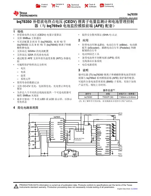
ProductFolderSample &BuyTechnicalDocumentsTools &SoftwareSupport &Communitybq78350ZHCSCR2–JULY2014 bq78350补偿放电终点电压(CEDV)锂离子电量监测计和电池管理控制器(与bq769x0电池监控模拟前端(AFE)配套)1特性•补偿放电终点电压(CEDV)电量计量算法•提供安全散列算法(SHA-1)认证•支持SMBus主机通信2应用•可灵活配置3到5节(bq76920)、6到10节•轻型电动车辆(LEV):电动自行车(eBike)、电动踏(bq76930)以及9到15节(bq76940)锂离子和磷板车(eScooter)、脚踏电动自行车(Pedelec)和踏酸铁锂电池板辅助自行车•支持高达320Ahr的电池配置•电动和园艺工具•支持高达320A的充放电电流•备用电池和不间断电源(UPS)系统•通过配套AFE支持外部负温度系数(NTC)热敏电•无线基站后备系统阻•电信电源系统•可编程保护特性的完全阵列–电压3说明–电流德州仪器(TI)bq78350锂离子和磷酸铁锂电池管理控–温度制器与bq769x0系列模拟前端(AFE)保护器件配套,–系统元件可提供全套电池管理系统(BMS)子系统,有助于加快•使用寿命的数据记录产品开发、缩短上市时间。
•支持CC-CV充电,包括预充电、充电禁止和充电暂停器件信息(1)•为多达八个不同的总线地址提供一个可选电阻器可部件号封装封装尺寸(标称值)编程SMBus从地址bq78350TSSOP(30)7.80mm x6.40mm •最多可驱动一个5段LED或LCD显示屏,以指示(1)要了解所有可用封装,请见数据表末尾的可订购产品附录。
充电状态4简化电路原理图bq78350ZHCSCR2–目录8.13Typical Characteristics (11)1特性 (1)9Detailed Description (12)2应用 (1)9.1Overview (12)3说明 (1)9.2Functional Block Diagram (12)4简化电路原理图 (1)9.3Feature Description (12)5修订历史记录 (2)9.4Device Functional Modes (14)6说明(续) (3)9.5Programming (15)7Pin Configuration and Functions (4)10Application and Implementation (16)8Specifications (6)10.1Application Information (16)8.1Absolute Maximum Ratings (6)10.2Typical Applications (16)8.2Handling Ratings (6)11Power Supply Recommendations (25)8.3Recommended Operating Conditions (6)12Layout (26)8.4Thermal Information (7)12.1Layout Guidelines (26)8.5Electrical Characteristics:Supply Current (7)12.2Layout Example (27)8.6Electrical Characteristics:I/O (7)13器件和文档支持 (28)8.7Electrical Characteristics:ADC (8)13.1相关文档 (28)8.8Electrical Characteristics:Power-On Reset (8)13.2商标 (28)8.9Electrical Characteristics:Oscillator (8)13.3静电放电警告 (28)8.10Electrical Characteristics:Data Flash Memory (8)13.4术语表 (28)8.11Electrical Characteristics:Register Backup (9)14机械封装和可订购信息 (28)8.12SMBus Timing Specifications (10)5修订历史记录日期修订版本注释2014年7月*最初发布版本bq78350 ZHCSCR2–JULY20146说明(续)bq78350控制器和bq769x0AFE支持3节到15节电池应用。
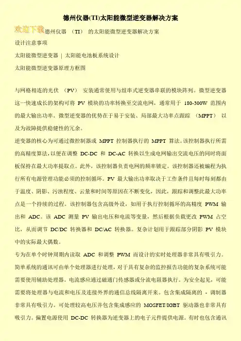
德州仪器(TI)太阳能微型逆变器解决方案德州仪器(TI)的太阳能微型逆变器解决方案设计注意事项太阳能微型逆变器| 太阳能电池板系统设计太阳能微型逆变器原理方框图与网格相连的光伏(PV)安装通常使用与组串式逆变器串联的模块阵列。
微型逆变器这一快速成长的架构可将PV 模块的功率转换至交流电网,通常用于180-300W 范围内的最大输出功率。
微型逆变器的优势在于易于安装、局部最大功率点跟踪(MPPT)以及为故障提供稳健性的冗余。
逆变器的核心为可通过微控制器或MPPT 控制器执行的MPPT 算法。
该控制器执行所需的高精度算法,以便在调整DC-DC 和DC-AC 转换以生成电网输出交流电压的同时将面板保持在最大功率提取点。
此外,该控制器负责电网的频率锁定。
该控制器还被编程为执行所有电源管理功能必须的控制循环。
PV 最大输出功率取决于工作条件且每时每刻都由于温度、阴影、污浊程度、云量和时间等原因在不断变化,因此,跟踪和调整此最大功率点是一个持续的过程。
该控制器包含高级外设,如用于执行控制循环的高精度PWM 输出和ADC。
该ADC 测量PV 输出电压和电流等变量,然后根据负载更改PWM 占空比,从而调节DC/DC 转换器和DC/AC 转换器。
复杂计划用于跟踪部分阴影PV 模块中的实际最大偶数。
专为在单个时钟周期内读取ADC 和调整PWM 而设计的实时处理器非常具有吸引力。
简单系统的通讯可由单个处理器进行处理,对于具有复杂的监控报告功能的复杂系统可能需要使用辅助处理器。
电流感应通过磁通门传感器或分流电阻器执行。
为安全起见,可能需要将处理器与电流和电压及连接外界的通信总线隔离开来。
包含集成隔离的- 调制器非常具有吸引力。
可处理较高电压并包含集成感应的MOSFET/IGBT 驱动器也非常具有吸引力。
偏置电源使用DC-DC 转换器为逆变器上的电子元件提供电源。
有时也包含通讯。
TI德州仪器EDI案例TI德州仪器市场占⽐的⽇益攀升与信息化不断成熟发展相遇,推动TI德州仪器与客户建⽴直接传输业务数据的⽅式,由此⼤量的客户可由从分销代理拿货转为直接向TI德州仪器下单——直供业务模式。
直供业务,利好双⽅。
为了完成直供业务模式的建⽴,2020年TI德州仪器⼤⼒推动了与客户的EDI对接。
直供模式下,TI德州仪器主要⾯临以下2个⽅⾯的挑战。
从业务层⾯看,挑战⼀是复杂的业务类型:订单、订单变更、发货、发票等;挑战⼆便是庞⼤的客户群,需要处理⼤量的业务数据。
这2个挑战放在⼀起,就意味着TI德州仪器需要解决内部数据管理、与客户间的数据传输的问题。
内部数据管理由成熟的业务系统来完成⾃动化的数据处理,⽽与客户之间进⾏的如此⼤量业务数据的传输,如果使⽤传统的邮件⽅式,必将带来由于⼤量⼈⼯操作导致失误的隐患,企业级的数据传输⽅案便就此登场——电⼦数据交换EDI。
TI德州仪器内部业务数据管理由业务系统来完成,⽽数据传输则需要供求双⽅共同对接来完成。
TI德州仪器在完成内部业务系统部署,并准备好⾜以对接成百上千客户的EDI系统后,便开始向客户⼤⼒推⼴EDI对接,以全⾯实现直供业务转型。
知⾏在2020年已协助数⼗家企业完成与TI德州仪器的EDI对接。
与TI德州仪器的EDI对接主要分为以下3个阶段:1、业务需求确认2、EDI业务测试3、EDI切⼊⽣产业务需求确认该阶段主要由TI德州仪器和客户两⽅的业务⼈员、IT(技术⼈员)⼀同进⾏线上会议。
需要注意的是,如果客户有业务系统,则由负责业务系统的IT和负责EDI的IT共同参会。
通过线上会议的⽅式,根据双⽅的实际业务需求,确认在EDI系统中所要传输的业务类型,及具体的业务场景所需求的业务数据。
TI德州仪器⽀持PO模式的客户在EDI中传输的业务类型包括:订单、订单响应、订单变更、订单变更响应、发货通知、发票;JIT模式下传输物料需求计划(长期)、物料需求计划响应、物料需求计划(短期)、发货通知、收货确认、发票。
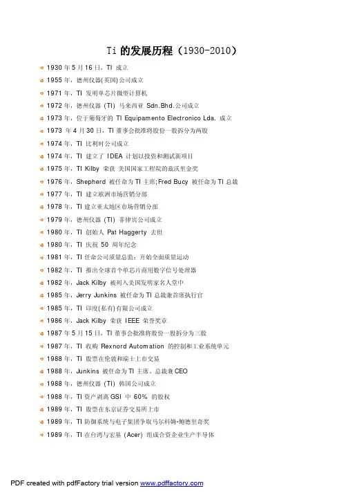
Ti的发展历程(1930-2010)1955年,德州仪器(英国)公司成立1972年,德州仪器(TI) 马来西亚Sdn.Bhd.公司成立1973 年4月30日,TI董事会批准将股份一股拆分为两股1974年,TI 建立了IDEA 计划以投资和测试新项目1976年,Shepherd 被任命为TI主席;Fred Bucy 被任命为TI总裁1978年,TI建立亚太地区市场营销分部1980年,TI 创始人Pat Haggerty 去世1981年,TI任命公司质量总监:开始全面质量运动1982年,Jack Kilby 被列入美国发明家名人堂中1985年,TI 印度(私有)有限公司成立1987年5月15日,TI董事会批准将股份一股拆分为三股1988年,TI 股票在伦敦和瑞士上市交易1988年,德州仪器(TI) 韩国公司成立1989年,TI 股票在东京证券交易所上市1989年,TI在台湾与宏基(Acer) 组成合资企业生产半导体1990年,TI 首次获得台湾质量奖1990年,TI在意大利阿维萨诺开办先进的晶圆厂1991年,德州仪器(TI) 新加坡公司获得国家品管圈奖1991年,TI在日本Tsukuba 建立研发中心1991年,德州仪器(TI) 英国公司全面质量获得Perkins 奖1992年,Materials & Controls Group 获得加拿大的全面质量奖1992年,TI防御系统与电子集团获得马尔科姆·鲍德里奇奖。
1993年,TI建立了主席办公室,Junkins 任主席、总裁兼CEO1993年,Jack Kilby 获得先进技术京都奖1995年,TI 创始人Erik Jonsson 去世1996年,TI收购Tartan, Inc.和Silicon Systems, Inc.1996年,Tom Engibous 被任命为TI总裁兼CEO;Jim Adams 被任命为TI主席1997年,荣获97年TI DSP产品推广奖1998年,TI 庆祝集成电路发明40 周年1998年,TI 丹麦公司成立1998年,TI收购:提供传感器和控制器的Integrated Sensor Solutions,Butterfly VLSI,Telogy Networks,ATL Research A/S,Libit Signal Processing,Unitrode,Power Trends六家半导体公司1998年,Engibous 被任命为TI主席、总裁兼CEO2000年,TI推出TMS320C64x DSP,每秒执行近90亿个指令,刷新DSP性能纪录2000年,Jack Kilby 获得诺贝尔物理奖,Jack Kilby 所发明的集成电路使微电子学成为所有现代技术的基础。
德州仪器(TI)产品命名规则产品分类及描述:该公司半导体产品分类较多,包括:存储器产品组、数字信号处理器(DSP)、电源管理IC、放大器和线性器件、微控制器、数据转换器、温度传感器和控制IC、标准线性器件等。
就我们日常所接到的询价情况来看,我将先主要介绍数字信号处理器(DSP)、微控制器、电源管理IC这三种。
◆数字信号处理器(DSP):DSP(digital singnal processor) 芯片,也称数字信号处理器,是一种具有特殊结构的微处理器。
DSP芯片的内部采用程序和数据分开的哈佛结构,具有专门的硬件乘法器,广泛采用流水线操作,提供特殊的DSP 指令,可以用来快速地实现各种数字信号处理算法。
根据数字信号处理的要求,DSP芯片一般具有如下的一些主要特点:(1)在一个指令周期内可完成一次乘法和一次加法。
(2)程序和数据空间分开,可以同时访问指令和数据。
(3)片内具有快速RAM,通常可通过独立的数据总线在两块中同时访问。
(4)具有低开销或无开销循环及跳转的硬件支持。
(5)快速的中断处理和硬件I/O支持。
(6)具有在单周期内操作的多个硬件地址产生器。
(7)可以并行执行多个操作。
(8)支持流水线操作,使取指、译码和执行等操作可以重叠执行。
与通用微处理器相比,DSP芯片的其他通用功能相对较弱些。
3、TI品牌电子芯片命名规则:SN54LS×××/HC/HCT/或SNJ54LS/HC/HCT中的后缀说明:SN或SNJ表示TI品牌SN军标,带N表示DIP封装,带J表示DIP(双列直插),带D表示表贴,带W表示宽体SNJ军级,后面代尾缀F或/883表示已检验过的军级.CD54LS×××/HC/HCT:◆无后缀表示普军级◆后缀带J或883表示军品级CD4000/CD45××:后缀带BCP或BE属军品后缀带BF属普军级后缀带BF3A或883属军品级TL×××:后缀CP普通级 IP工业级后缀带D是表贴后缀带MJB,MJG或带/883的为军品级TLC表示普通电压 TLV低功耗电压TMS320系列归属DSP器件, MSP430F微处理器BB产品命名规则:前缀ADS模拟器件后缀U表贴 P是DIP封装带B表示工业级前缀INA,XTR,PGA等表示高精度运放后缀U表贴 P代表DIP PA表示高精度TI产品命名规则:SN54LS×××/HC/HCT/或SNJ54LS/HC/HCT中的后缀说明:1、SN或SNJ表示TI品牌2、SN军标,带N表示DIP封装,带J表示DIP(双列直插),带D表示表贴,带W表示宽体3、SNJ军级,后面代尾缀F或/883表示已检验过的军级。
隔离测量系统TIVP1、TIVP05、TIVP02 数据表IsoVu 探头技术可在基准电压以 100V/ns 或更快速度回摆±60kV 时提供高达 ±2500V 的精确差分测量。
第二代探头采用IsoVu 第 2 代设计,其尺寸仅为第一代的五分之一,但却拥有所有的 IsoVu 技术优势。
凭借通用的 MMCX 连接器以及带宽、动态范围和共模抑制功能的结合,IsoVu Gen 2 探头为隔离探头技术树立了新标准,并能够通过 SiC 和 GaN 实现宽带隙电源设计。
IsoVu 探头的优势IsoVu 技术使用光纤供电和光模拟信号路径,以在测量系统和 DUT 之间实现完全光电隔离。
这种隔离的重要优势是允许探头在共模电压下独立浮动。
•DC 时 160 dB (100,000,000:1) CMRR•100 MHz 时高达 120 dB (1,000,000:1) CMRR • 1 GHz 时高达 80 dB (10,000:1) CMRR •±60 kV 共模电压范围•高达 ±2500 V 差分输入电压范围•高达 ±2500 V 偏置范围高电压和高带宽如果使用传统的差分探头,则必须在高带宽或高电压电平之间进行选择。
IsoVu 探头具有屏蔽同轴电缆和隔离层,可提供高带宽和 ±2500 V 的差分电压范围。
第 2 代 IsoVu 可提供200 MHz 、500 MHz 和 1 GHz 的带宽,以满足您的预算和性能要求。
高性能和便捷的连接IsoVu 探头端部具有一系列连接和附件,性能和可接入性较高。
探头可以直接连接到 MMCX 连接器,这种连接器价格便宜且使用广泛。
这样就可以提供稳定的、免提测试点,以及高带宽和共模抑制。
坚硬的金属主体屏蔽了中心导体,最大程度地减小了接地回路的面积,从而将干扰降至最低。
还可提供其他附件使探头端部能够用于多种连接方式。
另外还提供 0.100" 和 0.200" 间距的四方针端部以用于差分电压大于 ±250V 的场景。
使用德州仪器(TI )DLP ®结构光技术进行高精度3D 扫描Gina ParkDLP ® 产品工业经理Michael WangDLP Pico™ 产品营销Carey RitcheyDLP 产品工业业务发展经理德州仪器(TI )简介三维(3D)扫描是一种功能强大的工具,可以获取各种用于计量设备、检测设备、探测设备和3D 成像设备的体积数据。
当设计人员需要进行毫米到微米分辨率的快速高精度扫描时,经常选择基于 TI DLP® 技术的结构光系统。
3D 扫描系统的兴起简单的二维(2D)检测系统已经问世多年了,其工作机制通常是照亮物体并拍照,然后将拍摄图像与已知的标准 2D 参考件进行比较。
3D 扫描则增加了获取体积信息的能力。
引入 z 维数据可以测量物体的体积、平整度或粗糙度。
对于印刷电路板(PCB)、焊膏和机加工零件检测等行业而言,测量上述附加几何结构特征至关重要,而这是 2D 检测系统无法达到的。
此外,3D 扫描还可用于医疗、牙科和助听器制造等行业。
坐标测量机(CMM)是收集3D信息的首批工业解决方案之一。
探针物理接触物体表面,并结合每个点的位置数据来创建 3D 表面模型(图 1)。
后来出现了用于 3D 扫描的光学方法,如:结构光(图 2)。
结构光是将一组图案投射到物体上并用相机或传感器捕捉图案失真的过程。
然后利用三角计算方法计算数据并输出 3D 点云,从而生成用于测量、检查、检测、建模或机器视觉系统中各种计算的数据。
光学 3D 扫描受到青睐的原因在于不接触被测物体,并且可以非常快速甚至实时地获取数据。
借助 DLP 技术实现快速、智能的光图形生成对于光学 3D 扫描设备,DLP 技术通常在系统中用于产生结构光。
DLP 芯片是一种高反射铝微镜阵列,称为数字微镜器件(DMD)。
当 DMD 与照明光源和光学器件相结合时,这种精密复杂的微机电系统(MEMS)就可以为各种投影系统和空间光调制系统提供助力。
S T E L L A R I S E R R A T AStellaris ®LM3S1960RevA2ErrataThis document contains known errata at the time of publication for the Stellaris LM3S1960microcontroller.The table below summarizes the errata and lists the affected revisions.See the data sheet for more details.See also the ARM®Cortex™-M3errata,ARM publication number PR326-PRDC-009450v2.0.Table 1.Revision HistoryDescription Revision Date ■Added issue “Standard R-C network cannot be used on RST to extend POR timing”on page 5.■Clarified issue “General-purpose timer 16-bit Edge Count or Edge Time mode does not load reload value”on page 8to include Edge-Time mode.3.0August 2011■Added issue “Hibernation module does not operate correctly”on page 6,replacing previous Hibernation module errata items.■Minor edits and clarifications.2.10September 2010■Added issue “The RTRIS bit in the UARTRIS register is only set when the interrupt is enabled”on page 9.2.9July 2010■Added issue “External reset does not reset the XTAL to PLL Translation (PLLCFG)register”on page 5.2.8June 2010■Removed issue "Hibernation Module 4.194304-MHz oscillator supports a limited range of crystal load capacitance values"as it does not apply to this part.■Minor edits and clarifications.2.7May 2010■Removed issue "Writes to Hibernation module registers sometimes fail"as it does not apply to this part.■Added issue "Hibernation Module 4.194304-MHz oscillator supports a limited range of crystal load capacitance values."■Minor edits and clarifications.2.6April 2010■Removed issue "Setting Bit 7in I2C Master Timer Period (I2CMTPR)register may have unexpected results".The data sheet description has changed such that this is no longer necessary.■Minor edits and clarifications.2.5April 2010■Added issue “The General-Purpose Timer match register does not function correctly in 32-bit mode”on page 8.■Added issue "Setting Bit 7in I2C Master Timer Period (I2CMTPR)register may have unexpected results".2.4February 2010■"Hard Fault possible when waking from Sleep or Deep-Sleep modes and Cortex-M3Debug Access Port (DAP)is enabled"has been removed and the content added to the LM3S1960data sheet.2.3Jan 2010Started tracking revision history.2.2Dec 2009Stellaris LM3S1960A2Errata Table2.List of ErrataStellaris LM3S1960A2Errata1JTAG and Serial Wire Debug1.1JTAG pins do not have internal pull-ups enabled at power-on resetDescription:Following a power-on reset,the JTAG pins TRST,TCK,TMS,TDI,and TDO(PB7and PC[3:0])donot have internal pull-ups enabled.Consequently,if these pins are not driven from the board,twothings may happen:■The JTAG port may be held in reset and communication with a four-pin JTAG-based debugger may be intermittent or impossible.■The receivers may draw excess current.Workaround:There are a number of workarounds for this problem,varying in complexity and impact:1.Add external pull-up resistors to all of the affected pins.This workaround solves both issues ofJTAG connectivity and current consumption.2.Add an external pull-up resistor to TRST.Firmware should enable the internal pull-ups on theaffected pins by setting the appropriate PUE bits of the appropriate GPIO Pull-Up Select(GPIOPUR)registers as early in the reset handler as possible.This workaround addresses theissue of JTAG connectivity,but does not address the current consumption other than to limitthe affected period(from power-on reset to code execution).3.Pull-ups on the JTAG pins are unnecessary for code loaded via the SWD interface or via theserial boot loader.Loaded firmware should enable the internal pull-ups on the affected pins bysetting the appropriate PUE bits of the appropriate GPIOPUR registers as early in the resethandler as possible.This method does not address the current consumption other than to limitthe affected period(from power-on reset to code execution).Silicon Revision Affected:A21.2JTAG INTEST instruction does not workDescription:The JTAG INTEST(Boundary Scan)instruction does not properly capture data.Workaround:None.Silicon Revision Affected:A2Stellaris LM3S1960A2Errata2System Control2.1Clock source incorrect when waking up from Deep-Sleep mode insome configurationsDescription:In some clocking configurations,the core prematurely starts executing code before the main oscillator(MOSC)has stabilized after waking up from Deep-Sleep mode.This situation can cause undesirablebehavior for operations that are frequency dependent,such as UART communication.This issue occurs if the system is configured to run off the main oscillator,with the PLL bypassedand the DSOSCSRC field of the Deep-Sleep Clock Configuration(DSLPCLKCFG)register set touse the internal12-MHz oscillator,30-KHz internal oscillator,or32-KHz external oscillator.Whenthe system is triggered to wake up,the core should wait for the main oscillator to stabilize beforestarting to execute code.Instead,the core starts executing code while being clocked from thedeep-sleep clock source set in the DSLPCLKCFG register.When the main oscillator stabilizes,theclock to the core is properly switched to run from the main oscillator.Workaround:Run the system off of the main oscillator(MOSC)with the PLL enabled.In this mode,the clocksare switched at the proper time.If the main oscillator must be used to clock the system without the PLL,a simple wait loop at thebeginning of the interrupt handler for the wake-up event should be used to stall thefrequency-dependent operation until the main oscillator has stabilized.Silicon Revision Affected:A22.2PLL may not function properly at default LDO settingDescription:In designs that enable and use the PLL module,unstable device behavior may occur with the LDOset at its default of2.5volts or below(minimum of2.25volts).Designs that do not use the PLLmodule are not affected.Workaround:Prior to enabling the PLL module,it is recommended that the default LDO voltage setting of2.5Vbe adjusted to2.75V using the LDO Power Control(LDOPCTL)register.Silicon Revision Affected:A22.3I/O buffer5-V tolerance issueDescription:GPIO buffers are not5-V tolerant when used in open-drain mode.Pulling up the open-drain pinabove4V results in high current draw.Stellaris LM3S1960A2ErrataWorkaround:When configuring a pin as open drain,limit any pull-up resistor connections to the3.3-V power rail.Silicon Revision Affected:A22.4PLL Runs Fast When Using a3.6864-MHz CrystalDescription:If the PLL is enabled,and a3.6864-MHz crystal is used,the PLL runs4%fast.Workaround:Use a different crystal whose frequency is one of the other allowed crystal frequencies(see thevalues shown for the XTAL bit in the RCC register).Silicon Revision Affected:A22.5External reset does not reset the XTAL to PLL Translation(PLLCFG)registerDescription:Performing an external reset(anything but power-on reset)reconfigures the XTAL field in theRun-Mode Clock Configuration(RCC)register to the6MHz setting,but does not reset the XTALto PLL Translation(PLLCFG)register to the6MHz setting.Consider the following sequence:1.Performing a power-on reset results in XTAL=6MHz and PLLCFG=6MHz2.Write an8MHz value to the XTAL field results in XTAL=8MHz and PLLCFG=8MHz3.RST asserted results in XTAL=6MHz and PLLCFG=8MHzIn the last step,PLLCFG was not reset to its6MHz setting.If this step is followed by enabling thePLL to run from an attached6-MHz crystal,the PLL then operates at300MHz instead of400MHz.Subsequently configuring the XTAL field with the8MHz setting does not change the setting ofPLLCFG.Workaround:Set XTAL in PLLCFG to an incorrect value,and then to the desired value.The second changeupdates the register correctly.Do not enable the PLL until after the second change.Silicon Revision Affected:A22.6Standard R-C network cannot be used on RST to extend POR timingDescription:The standard R-C network on RST does not work to extend POR timing beyond the10ms on-chipPOR.Instead of following the standard capacitor charging curve,RST jumps straight to3V at powerStellaris LM3S1960A2Errataon.The capacitor is fully charged by current out of the RST pin and does not extend or filter thepower-on condition.As a result,the reset input is not extended beyond the POR.Workaround:Add a diode to block the output current from RST.This helps to extend the RST pulse,but alsomeans that the R-C is not as effective as a noise filter.Silicon Revision Affected:A23Hibernation Module3.1Hibernation module does not operate correctlyDescription:The Hibernation module on this microcontroller does not operate correctly.Workaround:This errata item does not apply to many Stellaris devices,including the LM3S1166,LM3S1636,LM3S1969,and LM3S2919.Refer to the Stellaris Product Selector Guide(/stellaris_search)and Errata documents to find an alternative microcontroller that meetsthe design requirements for your application.Silicon Revision Affected:A24Flash Controller4.1MERASE bit of the FMC register does not erase the entire FlasharrayDescription:The MERASE bit of the Flash Memory Control(FMC)register does not erase the entire Flash array.If the contents of the Flash Memory Address(FMA)register contain a value less than0x20000,only the first128KB of the Flash array are erased.If bit17(value of0x20000)is set,then only theupper address range of Flash(greater than128KB)is erased.Workaround:If the entire array must be erased,the following sequence is recommended:1.Write a value of0x00000000to the FMA register.2.Write a value of0xA4420004to the FMC register,and poll bit2until it is cleared.3.Write a value of0x00020000to the FMA register.4.Write a value of0xA4420004to the FMC register,and poll bit2until it is cleared.The entire array can also be erased by individually erasing all of the pages in the array.Stellaris LM3S1960A2ErrataSilicon Revision Affected:A25GPIO5.1GPIO input pin latches in the Low state if pad type is open drainDescription:GPIO pins function normally if configured as inputs and the open-drain configuration is disabled.Ifopen drain is enabled while the pin is configured as an input using the GPIO Alternate FunctionSelect(GPIOAFSEL),GPIO Open Drain Select(GPIOODR),and GPIO Direction(GPIODIR)registers,then the pin latches Low and excessive current(into pin)results if an attempt is made todrive the pin High.The open-drain device is not controllable.A GPIO pin is not normally configured as open drain and as an input at the same time.A user maywant to do this when driving a signal out of a GPIO open-drain pad while configuring the pad as aninput to read data on the same pin being driven by an external device.Bit-banging a bidirectional,open-drain bus(for example,I2C)is an example.Workaround:If a user wants to read the state of a GPIO pin on a bidirectional bus that is configured as anopen-drain output,the user must first disable the open-drain configuration and then change thedirection of the pin to an input.This precaution ensures that the pin is never configured as an inputand open drain at the same time.A second workaround is to use two GPIO pins connected to the same bus signal.The first GPIOpin is configured as an open-drain output,and the second is configured as a standard input.Thisway the open-drain output can control the state of the signal and the input pin allows the user toread the state of the signal without causing the latch-up condition.Silicon Revision Affected:A25.2GPIO pins may glitch during power supply ramp upDescription:Upon completing a POR(power on reset)sequence,the GPIO pins default to a tri-stated inputcondition.However,during the initial ramp up of the external V DD supply from0.0V to3.3V,theGPIO pins are momentarily configured as output drivers during the time the internal LDO circuit isalso ramping up.As a result,a signal glitch may occur on GPIO pins before both the external V DDsupply and internal LDO voltages reach their normal operating conditions.This situation can occurwhen the V DD and LDO voltages ramp up at significantly different rates.The LDO voltage ramp-uptime is affected by the load capacitance on the LDO pin,therefore,it is important to keep this loadat a nominal1µF value as recommended in the data sheet.Adding significant more capacitanceloading beyond the specification causes the time delay between the two supply ramp-up times togrow,which possibly increases the severity of the glitching behavior.Workaround:Ensuring that the V DD power supply ramp up is a fast as possible helps minimize the potential forGPIO glitches.Follow guidelines for LDO pin capacitive loading documented in the electrical sectionStellaris LM3S1960A2Errataof the data sheet.System designers must ensure that,during the V DD supply ramp-up time,possibleGPIO pin glitches can cause no adverse effects to their systems.Silicon Revision Affected:A26General-Purpose Timers6.1General-purpose timer Edge Count mode count error when timeris disabledDescription:When a general-purpose timer is configured for16-Bit Input Edge Count Mode,the timer(A or B)erroneously decrements by one when the Timer Enable(TnEN)bit in the GPTM Control(GPTMCTL)register is cleared(the timer is disabled).Workaround:When the general-purpose timer is configured for Edge Count mode and software needs to“stop”the timer,the timer should be reloaded with the current count+1and restarted.Silicon Revision Affected:A26.2General-purpose timer16-bit Edge Count or Edge Time mode doesnot load reload valueDescription:In Edge Count or Edge Time mode,the input events on the CCP pin decrement the counter until thecount matches what is in the GPTM Timern Match(GPTMTnMATCHR)register.At that point,aninterrupt is asserted and then the counter should be reloaded with the original value and countingbegins again.However,the reload value is not reloaded into the timer.Workaround:Rewrite the GPTM Timern Interval Load(GPTMTnILR)register before restarting.Silicon Revision Affected:A26.3The General-Purpose Timer match register does not functioncorrectly in32-bit modeDescription:The GPTM Timer A Match(GPTMTAMATCHR)register triggers a match interrupt when the lower16bits match,regardless of the value of the upper16bits.Workaround:None.Stellaris LM3S1960A2ErrataSilicon Revision Affected:A27UART7.1The RTRIS bit in the UARTRIS register is only set when the interruptis enabledDescription:The RTRIS(UART Receive Time-Out Raw Interrupt Status)bit in the UART Raw Interrupt Status(UARTRIS)register should be set when a receive time-out occurs,regardless of the state of theenable RTIM bit in the UART Interrupt Mask(UARTIM)register.However,currently the RTIM bitmust be set in order for the RTRIS bit to be set when a receive time-out occurs.Workaround:For applications that require polled operation,the RTIM bit can be set while the UART interrupt isdisabled in the NVIC using the IntDisable(n)function in the StellarisWare Peripheral Driver Library,where n is21,22,or49depending whether UART0,UART1or UART2is used.With thisconfiguration,software can poll the RTRIS bit,but the interrupt is not reported to the NVIC.Silicon Revision Affected:A28PWM8.1PWM pulses cannot be smaller than dead-band timeDescription:The dead-band generator in the PWM module has undesirable effects when receiving input pulsesfrom the PWM generator that are shorter than the dead-band time.For example,providing a4-clock-wide pulse into the dead-band generator with dead-band times of20clocks(for both risingand falling edges)produces a signal on the primary(non-inverted)output that is High except for40clocks(the combined rising and falling dead-band times),and the secondary(inverted)output isalways Low.Workaround:User software must ensure that the input pulse width to the dead-band generator is greater thanthe dead-band delays.Silicon Revision Affected:A28.2PWM interrupt clear misses in some instancesDescription:It is not possible to clear a PWM generator interrupt in the same cycle when another interrupt fromthe same PWM generator is being asserted.PWM generator interrupts are cleared by writing a1to the corresponding bit in the PWM Interrupt Status and Clear(PWMnISC)register.If a write toclear the interrupt is missed because another interrupt in that PWM generator is being asserted,Stellaris LM3S1960A2Erratathe interrupt condition still exists,and the PWM interrupt routine is called again.System problemscould result if an interrupt condition was already properly handled the first time,and the softwaretries to handle it again.Note that even if an interrupt event has not been enabled in the PWMInterrupt and Trigger Enable(PWMnINTEN)register,the interrupt is still asserted in the PWMRaw Interrupt Status(PWMnRIS)register.Workaround:In most instances,performing a double-write to clear the interrupt greatly decreases the chancethat the write to clear the interrupt occurs on the same cycle as another interrupt.Because eachgenerator has six possible interrupt events,writing the PWMnISC register six times in a rowguarantees that the interrupt is cleared.If the period of the PWM is small enough,however,thismethod may not be practical for the application.Silicon Revision Affected:A28.3PWM generation is incorrect with extreme duty cyclesDescription:If a PWM generator is configured for Count-Up/Down mode,and the PWM Load(PWMnLOAD)register is set to a value N,setting the compare to a value of1or N-1results in steady state signalsinstead of a PWM signal.For example,if the user configures PWM0as follows:■PWMENABLE=0x00000001–PWM0Enabled■PWM0CTL=0x00000007–Debug mode enabled–Count-Up/Down mode–Generator enabled■PWM0LOAD=0x00000063–Load is99(decimal),so in Count-Up/Down mode the counter counts from zero to99and back down to zero(200clocks per period)■PWM0GENA=0x000000b0–Output High when the counter matches comparator A while counting up–Output Low when the counter matches comparator A while counting down■PWM0DBCTL=0x00000000–Dead-band generator is disabledIf the PWM0Compare A(PWM0CMPA)value is set to0x00000062(N-1),PWM0should output a2-clock-cycle long High pulse.Instead,the PWM0output is a constant High value.If the PWM0CMPA value is set to0x00000001,PWM0should output a2-clock-cycle long negative(Low)pulse.Instead,the PWM0output is a constant Low value.Stellaris LM3S1960A2ErrataWorkaround:User software must ensure that when using the PWM Count-Up/Down mode,the compare valuesmust never be1or the PWMnLOAD value minus one(N-1).Silicon Revision Affected:A28.4PWMINTEN register bit does not function correctlyDescription:In the PWM Interrupt Enable(PWMINTEN)register,the IntPWM0(bit0)bit does not functioncorrectly and has no effect on the interrupt status to the ARM Cortex-M3processor.This bit shouldnot be used.Workaround:PWM interrupts to the processor should be controlled with the use of the PWM0-PWM2Interruptand Trigger Enable(PWMnINTEN)registers.Silicon Revision Affected:A28.5Sync of PWM does not trigger"zero"actionDescription:If the PWM Generator Control(PWM0GENA)register has the ActZero field set to0x2,then theoutput is set to0when the counter reaches0,as expected.However,if the counter is cleared bysetting the appropriate bit in the PWM Time Base Sync(PWMSYNC)register,then the"zero"actionis not triggered,and the output is not set to0.Workaround:None.Silicon Revision Affected:A28.6PWM"zero"action occurs when the PWM module is disabledDescription:The zero pulse may be asserted when the PWM module is disabled.Workaround:None.Silicon Revision Affected:A2August04,2011/Rev.3.011Texas Instruments9QEI 9.1QEI index resets position when index is disabledDescription:When the QEI module is configured to not reset the position on detection of the index signal (thatis,the ResMode bit in the QEI Control (QEICTL)register is 0),the module resets the position whenthe index pulse occurs.The position counter should only be reset when it reaches the maximumvalue set in the QEI Maximum Position (QEIMAXPOS)register.Workaround:Do not rely on software to disable the index pulse.Do not connect the index pulse if it is not needed.Silicon Revision Affected:A29.2QEI hardware position can be wrong under certain conditionsDescription:The QEI Position (QEIPOS)register can be incorrect if the QEI is configured for quadrature phasemode (SigMode bit in QEICTL register =0)and to update the position counter of every edge ofboth PhA and PhB (CapMode bit in QEICTL register =1).This error can occur if the encoder isstepped in the reverse direction,stepped forward once,and then continues in the reverse direction.The following sequence of transitions on the PhA and PhB pins causes the error:PhBAssuming the starting position prior to the above PhA and PhB sequence is 0,the position after thefalling edge on PhB should be -3,however the QEIPOS register will show the position to be -1.Workaround:Configure the QEI to update the position counter on every edge on PhA only (CapMode bit in QEICTLregister =0).The effective resolution is reduced by 50%.If full resolution position detection is requiredby updating the position counter on every edge of both PhA and PhB ,no workaround is available.Hardware and software must take this into account.Silicon Revision Affected:A2August 04,2011/Rev.3.0Texas Instruments12Stellaris LM3S1960A2ErrataCopyright©2007-2011Texas Instruments Incorporated All rights reserved.Stellaris and StellarisWare are registered trademarks of Texas Instruments Incorporated.ARM and Thumb are registered trademarks and Cortex is a trademark of ARM Limited.Other names and brands may be claimed as the property of others.Texas Instruments Incorporated108Wild Basin,Suite350Austin,TX78746/stellaris/sc/technical-support/product-information-centers.htmAugust04,2011/Rev.3.0Texas Instruments13IMPORTANT NOTICETexas Instruments Incorporated and its subsidiaries(TI)reserve the right to make corrections,modifications,enhancements,improvements, and other changes to its products and services at any time and to discontinue any product or service without notice.Customers should obtain the latest relevant information before placing orders and should verify that such information is current and complete.All products are sold subject to TI’s terms and conditions of sale supplied at the time of order acknowledgment.TI warrants performance of its hardware products to the specifications applicable at the time of sale in accordance with TI’s standard warranty.Testing and other quality control techniques are used to the extent TI deems necessary to support this warranty.Except where mandated by government requirements,testing of all parameters of each product is not necessarily performed.TI assumes no liability for applications assistance or customer product design.Customers are responsible for their products and applications using TI components.To minimize the risks associated with customer products and applications,customers should provide adequate design and operating safeguards.TI does not warrant or represent that any license,either express or implied,is granted under any TI patent right,copyright,mask work right, or other TI intellectual property right relating to any combination,machine,or process in which TI products or services are rmation published by TI regarding third-party products or services does not constitute a license from TI to use such products or services or a warranty or endorsement e of such information may require a license from a third party under the patents or other intellectual property of the third party,or a license from TI under the patents or other intellectual property of TI.Reproduction of TI information in TI data books or data sheets is permissible only if reproduction is without alteration and is accompanied by all associated warranties,conditions,limitations,and notices.Reproduction of this information with alteration is an unfair and deceptive business practice.TI is not responsible or liable for such altered rmation of third parties may be subject to additional restrictions.Resale of TI products or services with statements different from or beyond the parameters stated by TI for that product or service voids all express and any implied warranties for the associated TI product or service and is an unfair and deceptive business practice.TI is not responsible or liable for any such statements.TI products are not authorized for use in safety-critical applications(such as life support)where a failure of the TI product would reasonably be expected to cause severe personal injury or death,unless officers of the parties have executed an agreement specifically governing such use.Buyers represent that they have all necessary expertise in the safety and regulatory ramifications of their applications,and acknowledge and agree that they are solely responsible for all legal,regulatory and safety-related requirements concerning their products and any use of TI products in such safety-critical applications,notwithstanding any applications-related information or support that may be provided by TI.Further,Buyers must fully indemnify TI and its representatives against any damages arising out of the use of TI products in such safety-critical applications.TI products are neither designed nor intended for use in military/aerospace applications or environments unless the TI products are specifically designated by TI as military-grade or"enhanced plastic."Only products designated by TI as military-grade meet military specifications.Buyers acknowledge and agree that any such use of TI products which TI has not designated as military-grade is solely at the Buyer's risk,and that they are solely responsible for compliance with all legal and regulatory requirements in connection with such use. TI products are neither designed nor intended for use in automotive applications or environments unless the specific TI products are designated by TI as compliant with ISO/TS16949requirements.Buyers acknowledge and agree that,if they use any non-designated products in automotive applications,TI will not be responsible for any failure to meet such requirements.Following are URLs where you can obtain information on other Texas Instruments products and application solutions:Products ApplicationsAudio /audio Communications and Telecom /communicationsAmplifiers Computers and Peripherals /computersData Converters Consumer Electronics /consumer-appsDLP®Products Energy and Lighting /energyDSP Industrial /industrialClocks and Timers /clocks Medical /medicalInterface Security /securityLogic Space,Avionics and Defense /space-avionics-defense Power Mgmt Transportation and Automotive /automotiveMicrocontrollers Video and Imaging /videoRFID OMAP Mobile Processors /omapWireless Connctivity /wirelessconnectivityTI E2E Community Home Page Mailing Address:Texas Instruments,Post Office Box655303,Dallas,Texas75265Copyright©2011,Texas Instruments Incorporated。
TI终面!德州仪器主要竞争对手包括微型芯片技术公司、Cypress半导体公司、集成设备技术公司、三星电子以及Xilinx公司。
面试题:角色:面试者扮演诚信半导体有限公司的销售工程师刘佳(新人) 刘佳主管A宏瑞公司技术总监B(面试官扮演)公司背景:刘佳主要负责诚信半导体消费类芯片的销售,宏瑞公司主要生产智能手机,在前期产品S2.S3上,宏瑞应用了大量诚信生产的电源管理芯片、触摸屏管理芯片等,交易额大概前期4000万左右,诚信近期刚开发了一款移动终端处理芯片hero5.希望能用在宏瑞生产的S4智能手机上,宏瑞近期发展较快,这两年每年都有超过15%的增长。
在终端处理芯片上,诚信拥有主要竞争对手HT B因为要参加另一个大公司的商务投标,本来已经约好了要和A商谈,临时决定派遣刘佳进行和A进行会面。
任务:询问hero在S4上的最近的测试情况,及S4的量产计划。
相关信息:1、hreo5最近六个月已经在宏瑞进行了相关测试,发现的问题得到了反馈并已经由公司的工程师处理2、hreo5的报价为每颗30美元3、由于产能紧张,最近两个月能提供给宏瑞的芯片数量为10万片。
(貌似还有其他的,记不清楚了)大体上就是这个样子了,然后就是各种刁难,为什么价格高,不能做决定为什么你还来,如果价格不能低的话那你现在就可以回去了等等。
各地案例应该会不一样,各位好运.价格高:一分价钱一分货,良品率好,性能稳定,主流旗舰手机首选。
不能做决定:来的目的是做一个前期交流,了解测试情况和量产情况。
并且把你们的需求(价格,性能,技术支持)上做个了解并反馈。
价格不能低:价格这个由多个因素决定的,我个人现在目前不能给明确答复。
但宏瑞公司如何很在在意这块芯片的价格的话,我会把你们的需求明确反馈,和A 总及其他人员商量,尽最大努力给你们一个合适的价位,降低你们的成本。
其他公司有没有用:目前很多家主流手机公司都在测试我们的芯片,反馈很好。
其中有不少公司有进一步的合作意愿。
德州仪器公司(TI)简介
德州仪器(TI)公司是世界上最大的半导体公司之一。
TI始终致力于提供创新半导体技术,帮助客户开发世界最先进的电子产品。
其模拟、嵌入式处理以及无线技术不断深入至生活的方方面面,从数字、通信、娱乐到医疗服务、汽车系统以及各种广泛的应用,无所不在。
在 TI 发展之初,公司的目标是利用公司独有的技术能力从根本上颠覆传统市场,创造全新的市场。
TI的发展历程中始终贯穿一条清晰的主线,就是运用越来越先进的实时信号处理技术,实现从量变到质变的进步,真真切切地不断改变世界。
∙TI 是第一家全球化的半导体公司;
∙TI 模拟芯片被广泛用于各种电子产品,从便携式超声波设备到机顶盒,从电子书到计算机服务器,从机器人到 LED 路灯。
∙一个 100 瓦灯泡的功耗相等于 6,000 万个 MSP430 微处理器。
∙TI无线连接芯片组出货量已经超过 10 亿片。
∙TI 的 Jack Kilby 于 1958 年发明集成电路。
∙TI 于 1967 年发明手持计算器。
∙图形计算器的使用让学生对数学的态度大为改善。
∙DLP® 影像技术非常灵活,可以驱动30米的电影屏幕或把手机变成投影仪。
∙TI 拥有两项DLP® 技术艾美奖。
∙TI 是首家赢得美国绿色环保建筑委员会 (the U.S. Green Building Council) 认证的可建造环保制造设施的半导体企业。
∙2011 年 TI 的废弃物回收利用率达 92%。
电子元器件采购网 -万联芯城,提供一站式电子元器件配单业务,原装全现货TI代理_德州仪器代理品牌元件优势供应,货源渠道均来自原厂及代理商。
当天报价,当天发货。
解决终端客户采购需求。
点击进入万联芯城
TI代理_德州仪器代理是一家美国技术公司,设计和制造半导体和各种集成电路,并将其销售给全球的电子设计师和制造商。
[4] TI总
部位于美国德克萨斯州达拉斯市,根据销售量,是全球十大半导体公司之一。
[5]TI代理_德州仪器代理的重点是开发模拟芯片和嵌入式处理器,德州仪器占其收入的80%以上。
[6] TI还生产TI数字光处理(DLP)技术和教育技术[6]产品,包括计算器,微控制器和多核处理器。
迄今为止,TI在全球拥有43,000多项专利。
[7]
德州仪器于1951年重组了地球物理服务公司,该公司成立于1930年,该公司生产用于地震工业的设备以及国防电子设备。
[8] TI代理_德州仪器代理于1954年制造了世界上个商用硅晶体管[9],并于1954年设计并制造了个晶体管收音机.Jack Kilby于1958年在TI中央研究实验室工作时发明了集成电路。
TI还于1967年发明了手持式计算器,并于1970年推出了款单片微控制器(MCU),它将计算的所有元素组合到一块硅片上。
[10]
1987年,TI发明了数字光处理器件(也称为DLP芯片),作为该公司屡获殊荣的DLP技术和DLP Cinema的基础。
[10] 1990年,TI推出了流行的TI-81计算器,使其成为图形计算器行业的领导者。
1997年,其防务业务被出售给雷神公司,这使得TI能够加强对数字解决方案的关注。
[11]在2011年收购美国国家半导体后,该公司拥有近45,000个模拟产品和客户设计工具的组合,[12]使德州仪器成为全球大的模拟技术组件制造商。
德州仪器由Cecil H. Green,J。
Erik Jonsson,Eugene McDermott 和Patrick E. Haggerty于1951年创立.McDermott是1930年地球物理服务公司(GSI)的原始创始人之一.McDermott,Green和Jonsson 是1941年收购该公司的GSI员工。
1945年11月,Patrick Haggerty 被聘为实验室和制造(L&M)部门的总经理,专注于电子设备。
[13]到1951年,拥有国防合同的L&M部门的增长速度超过了GSI的地球物理部门。
该公司进行了重组,初更名为通用仪器公司。
由于已经有一家名为General Instrument的公司,该公司同年更名为德州仪器。
从1956年到1961年,达拉斯的Fred Agnich,后来成为德克萨斯众议院的共和党成员,是德州仪器公司的总裁。
Geophysical Service,Inc。
成为德州仪器的子公司。
1988年初,大部分GSI被出售给了Halliburton公司。
德州仪器致力于创造,德州仪器制造和营销有用的产品和服务,以满足全球客户的需求。
[14]
- Patrick Haggerty,德州仪器目的声明
地球物理服务公司[编辑]
1930年,J。
Clarence Karcher和Eugene McDermott创立了地球物理服务公司,这是石油工业地震勘探服务的早期提供商。
1939年,该公司重组为Coronado Corp.,一家拥有地球物理服务公司(GSI)的石油公司,现为子公司。
1941年12月6日,McDermott和其他三位GSI员工J. Erik Jonsson,Cecil H. Green和H.B.孔雀购买了
GSI。
在第二次世界大战期间,GSI扩大了德州仪器的服务范围,包括美国陆军,Signal Corps和美国海军的电子设备。
1951年,公司更名为德州仪器,GSI成为新公司的全资子公司。
TI-GSI的早期成功故事发生在1965年,当时GSI能够(根据高机密政府合同)监测苏联在Vela Uniform(海拉项目的一个子集)海洋下的地下核武器测试,以验证部分核禁试条约。
[15]
德州仪器还继续生产用于地震行业的设备,GSI继续提供地震服务。
在销售(并重新购买)GSI之后,TI终于在1988年将该公司卖给了Halliburton,此时GSI不再作为一个独立的实体存在。
半导体[编辑]
1952年初,TI代理_德州仪器代理以25,000美元的价格购买了AT&T制造部门Western Electric Co.生产锗晶体管的专利许可,并于年底开始生产。
[引证需要]
1953年1月1日,Haggerty将Gordon Teal带到德州仪器担任研究主管。
戈登带来了他在种植半导体晶体方面的专业知识。
Teal的个任务是组织TI的中央研究实验室(CRL),Teal基于他之前在贝尔实验室的经验。
[引证需要]
在他的新员工中,Willis Adcock于1953年初加入TI.Adcock喜欢Teal是一名物理化学家,他开始领导一个专注于制造“生长结硅单
晶小信号晶体管”的小型研究小组.Adcock后来成为位TI首席研究员。
[16]
个硅晶体管和集成电路[编辑]
晶体管“逻辑”芯片,TI生产的集成电路
1954年1月贝尔实验室的Morris Tanenbaum创造了个可用的硅晶体管。
[17]这项工作是在1954年春季的IRE非固态设备非正式会议上报道的,后来发表在应用物理学杂志上。
1954年4月,TI的Gordon Teal独立工作,德州仪器创建了个商用硅晶体管并于1954年4月14日对其进行了测试。
1954年5月10日,在俄勒冈州代顿的无线电工程师协会(IRE)全国机载电子会议上,蒂尔提交了一篇论文:“硅和锗材料和器件的新发展”,[18]
1954年,德州仪器设计并制造了台晶体管收音机。
Regency TR-1使用锗晶体管,因为硅晶体管在当时要贵得多。
这是Haggerty努力增加市场对晶体管的需求。
TI代理_德州仪器代理中央研究实验室的员工Jack Kilby于1958年发明了集成电路。
[1]基尔比在1958年7月记录了他关于集成电路的初步想法,并于1958年9月12日成功演示了世界上个工作集成电路。
[19]六个月后,Fairchild Semiconductor的Robert Noyce(继续共同创立英特尔)独立开发了集成互连的集成电路,并且也被认为是集成电路的发明者。
[20] 1969年,Kilby被授予国家科学奖章,并于1982年入选国家发明家名人堂。
[21] Kilby还因其发明集成电路而
获得2000年诺贝尔物理学奖。
[22] Noyce的芯片由Fairchild制造,由硅制成,而Kilby的芯片则由锗制成。
2008年,TI代理_德州仪器代理在Jack Kilby之后将其新开发实验室命名为“Kilby Labs”。
[23]
2011年,英特尔,三星,LG,ST-Ericsson,华为HiSilicon Technologies子公司Via Telecom以及其他三家未公开的芯片制造商获得了Arteris Inc.和德州仪器公司开发的C2C链接规范的许可。