埃斯顿RES56-A旋转变压器选型手册
- 格式:pdf
- 大小:340.84 KB
- 文档页数:1
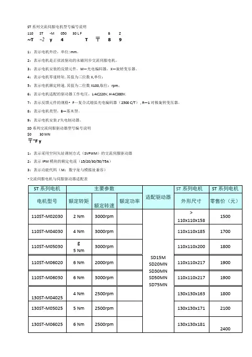
ST系列交流伺服电机型号编号说明110 ST -M 050 30 L F B Z~T ~2y 4 T 〒8 91:表示电机外径,单位:mm。
2:表示电机是正弦波驱动的永磁同步交流伺服电机。
3:表示电机安装的反馈元件,M—光电编码器,X—旋转变乐器。
4:表示电机零速转矩.其值为三位数X,单位:5:表示电机额定转速.其值为二位数X100,取位:rpm。
6:表示电机适配的驱动器工作电圧,L-AC220V, H-AC380V.7:表示反馈元件的规格• F—复合式増虽光电编码器(2500 C/T) , R—1对极旋转变压器。
8:表示电机类型,B—基木型。
9:表示电机安装J'失电制动器。
SD系列交流伺服驱动器型号编号说明$0 30 MN〒"F y1:表示采用空间矢址调制方式(SVPWM)的交流伺服驱动器2:表示IPM模块的额定电流(15/20/30/50/75A)3:表示功能代码(M:数字址与模拟址兼容)•交流伺服电机与伺服驱动器适配表ST系列交流伺服电机安装尺寸nd 系列电|flL¥辿斡超(Kt>24 5 615S (3W> 185(227| )200 C212)217 <25^>H(»ti)7G102118)34注:M 墟内的牧的人爲久也衲型净的K 及.13()屆列电机多毬其M (»!)j 56 ■ *w 1. 1 10 15 A ((■«>163 ⑴09〉171 <21J)181 (223)I9» C237> 219 C261 )2E7 <31»)B (ran?80«9113135IMil>捂£闯的说血奶& X »t 丸功紳K 收SD15M 伺服驱动器安装尺寸110205«0^546 130ON1电机倍号反馀 61维制话号辑入214.5a■Cn§tn讣T 讥R 远VU r r耳©ru 弋WTSR 用^^^缪SD20MN 、30MN用能zn4CN1<机伯号反馈 CW2桧制佶号输凡相关标签:电札伺服5相关产品WA-99UZ步进电机的简収原相关新闻2011电源管理及LED粘彩方案且看海默科技2011 年03 }] 18 日安淼羌半导体将在HC-China 2011展出多种岛能效方案2011年03丿J 18日步进电机发热问題及对策2011年03丿J 18日泽野驱动器2011隆重上市2011 年03 )\ 18 13Allegro推出汽乍级可编程双极步进电动机驱动器IC2011年03丿J 18日泽野电机34系列步进电机上市2011 年03 Jj 15 日步进电机14问2011 年03 月15 EI用集成脉冲输出触发步进电机驱动器2011 年03 )\ 15 13白山机电一DM系列产品荣登2011SIAF展•…2011 <1 0315 I I加快电机动力系统技术创新 .............................. 2011年03丿J 15 11交流伺服系统在许女性能方面都优于步进电机 ...................... 2011勺03丿J 09交流伺服电机传动技术实现了高精度的位宜控制 ...................... 2011 <| 03丿J 09 I I低速大扭矩交流伺服电机驱动单•嫖杆挤出机 ...................... 2011年03 09日北仑伺服电机产业蓬勃兴起 .............................. 2011年03丿J 09日伺服电机与变频电机的区别 .............................. 2011年03丿J 09日哈电填补世界“百万级"水轮发电机通风技术空白 ...................... 2011年03丿]02 I I日木电器零吿商山ID电机6月进津............................ 2011年03丿]02日联宜电机续发行亿元短期融资券 .......................... 2011 if 03 JJ 02 II对决:优派Pro8200vs 三菱电机HC4000 .................................................... 2011 年03 }\ 02 I三菱电机放电加工机技术交流会举办 ......................... 2011 i] 03丿]02 F-I步进电机和交流伺服电机性能比较 ........................... 2011 <| 01 14 EI伺服电机被步进脉冲控制的优点 ............................ 2011年01 JJ 14 0三菱电梯创新成产业发展新动力 ............................ 2011年01丿J 14日威力变频洗衣机智能洗涤见节能 ............................ 2011年01 )] 14 IEI西门子电气传动有限公司牵引电机及风力发电机扩大产能 .................. 2011年01丿J 14 II 交流伺服电机传动技术实现了高精度的位宜控制 .................... 2011角01丿j 12 I I伺服电机被步进脉冲控制的优点 ............................ 2011年01 JJ 12 H2010年推出具有运动控制功能的伺服专用芯片...................... 2011 01 JJ 12伺服电机满足运动过程中精准的控制方式 ........................ 2011 01丿J 12日环形变圧器的应用指南 ................................. 2011年01丿J 12 13宙赛:步进伺服专家运动控制先锋 ........................... 2011年01丿]07 II交流伺服电机传动技术实现了高精度的位宜控制 .................... 2011卸01丿J 07 EI 瑞萨电子32位MCU在伺服电机中的应用.......................... 2011年01 J1 07申力步进电机二相八线接线方法 ............................ 2011年01丿J 07 :如何用简单的方法调整两相步进电机通电后的转动方向 .................. 2011 01丿]05 IJ 一种步进电机及其驱动器干扰问题解决措施 ........................ 2011〈01 05 II 14届中国(国际)小电机展掠影…....... 2011 •! 01 d 05 II 线切割机床驱动选型支招 ............................... 2011年01丿J 05日步进马达市场总结分析及发展趋魁 ........................... 2010年12丿J 31 H步进电机应用2010年12丿J 31 H运动控制系统简介 (2010)年12丿J 31日发现步进电机定位不准怎么办 .............................. 2010年12 J] 31 I I何为驱动器的细分. ................................ 2010年12 JJ 31日步进电机使用时的注意事项 ............................. 2010年12丿J 29日解决步进电机干拢问題的发法 .............................. 2010年12丿]29日关于步进电机的发热 ................................. 2010年12丿J 29 II关于步进电机和伺服电机的区别 ............................ 2010年12丿J 29日乐创自动化推出三相混合式步进电机驱动器 ........................ 2010年12 29 II步进电机原理及使用说明 ............................... 2010年12丿J 22日2010 年 12 /J 22 13 201012月22日2010年12丿]22日 2010 年 12 }] 15 日2010 年 11 )\ 242010 年 11 JJ 03 E1 2010年n 丿J oi 日2010 年 10 JJ 21 日步进电机控制器的设计 一体化步进电机驱动器全电动注塑机电控原理步进电机的种类和特点关于步进电机的发热步进电机的一些基木参数步进也机驱动器的故障分析 步进电机的最新技术发展60ST-M 系列交流伺服电机技术参详 绝缘电阴 ----- 500VDC 100MW Min绝缘强度 ------- 1500VAC IMinute环境温度——-2O°C 〜+50C 绝缘等级一一B 级60ST-M 系列交流伺服电机优点1、 无电刷和换向器•因此工作可靠,对维护和保养要求低。
NSC 560系列数字式变压器保护装置技术说明书国电南京自动化股份有限公司2005年6月* 本公司保留对此说明书修改的权利,请注意最新版本资料目次1 装置简介 (1)2 装置硬件 (3)2.1机箱结构 (3)3 保护原理 (4)3.1变压器(差动)保护原理(最大可判五侧差动) (4)3.2 二次谐波制动 (6)3.3TA断线报警及闭锁 (6)3.4非电量保护的事件记录及延时 (6)3.5 三段式复合电压闭锁方向过流保护 (8)3.6零序过电流元件 (9)3.7间隙保护元件 (9)3.8过负荷元件 (10)3.9TV断线检测 (10)3.10数据记录 (10)4 定值及整定说明 (11)4.1NSC565数字式变压器差动保护装置的整定值清单及说明 (11)4.2NSC566数字式变压器后备保护装置的整定值清单及说明 (12)5 附图 (16)附图1:NSC565主变差动保护装置背板端子图 (116)附图2:NSC566主变后备保护装置背板端子图 (12)1 装置简介NSC 560系列数字式变压器保护装置是适用于110kV及以下电压等级的成套变压器保护,提供二次谐波制动的比率差动保护,开关量保护,及反应相间故障的后备保护。
整套装置在硬件上由几个独立的单元构成:差动保护单元、开关量保护单元及按侧配置的后备保护单元,各部分在电气及结构上均互相独立,各侧的后备保护单元同时完成该侧的测量控制功能。
本保护装置每个电气保护单元的基本配置为两个CPU插件,其一为由32位微处理器构成的保护功能单元,该单元配置了大容量的RAM和Flash Memory,具有极强的数据处理、逻辑运算和信息存储能力;另一CPU由总线不出芯片的单片机构成通用的人机接口单元。
两个CPU插件之间相互独立,无依存关系。
各种保护功能及自动化功能均由软件实现。
1)装置特点1:全中文汉化液晶显示,人机界面友善,操作方面。
2:专用测量模块,包括电度计量在内的各种测量及计量精度可达0.5级3:提供累计脉冲电度的接入端4:配置了充足的开关量输入端,方便外部遥信量的接入5:装置自带操作回路及就地操作把手,不需附加其它设备即可直接跳合开关6:设置了高精度的时钟芯片,并配置有GPS硬件对时回路,便于全系统时钟同步7:配备高速以太网络通信接口,并集成了IEC 60870-5-103标准通信规约8:完善的故障录波功能2)完备的保护功能配置表1 本系列产品的型号及功能配置表功能NSC 565 NSC 566差动速断√二次谐波制动的比率差动√TA(1)断线闭锁差动√过流保护√过负荷√负序过电压闭锁√低电压闭锁√零序过流√间隙过流√间隙过压保护√电流启动风扇√电流闭锁调压过负荷告警√功能NSC 565 NSC 566 重瓦斯√调压重瓦斯√冷却故障√压力释放√轻瓦斯√调压轻瓦斯√油温高√遥控功能压板√遥测测量级TA √保护级TV √遥信√√遥控√电度脉冲计量√GPS对时√√防误闭锁√√远方管理√√3)NSC566装置的监控功能1:遥测:Ia,Ib,Ic,Ua,Ub,Uc,P,Q,f 等模拟量的遥测2:遥控:正常断路器的遥控分合3:遥信:16路遥信开入量的采集、装置遥信变位、事件遥信等4:遥脉:2路电度脉冲输入5:开出:装置具有13路开出,其中10路由于驱动出口跳闸继电器,3路用于预告警信号驱动。

Type DTL, De-energized Tap Changer Application, Installation & Selection GuideIZUA 4643-212Instruction LeafletScopeThis leaflet contains general information about ordering and installing the type DTL de-energized tap changer. These in-structions do not describe all possible contingencies that may arise during installation, operation, or maintenance of the tap changer, nor does it describe all details and variations of the equipment. If you require additional information regarding this installation and the operation or maintenance of your equip-ment, contact the local representative of ABB.Safety DefinitionsSafety notations are intended to alert personnel of possible personal injury, property damage, or even death. They have been inserted in this instructional text prior to the step in which the condition is cited.The safety notations are headed by one of three hazard intensity levels, which are defined as follows:DANGER- immediate hazard that will result in severe personal injury, property damage, or death.WARNING- hazard or unsafe practice that could result in personal injury, property damage, or death. CAUTION- hazard or unsafe practice, which could result in minor personal injury, or property damage. IntroductionT he type DTL de-energized tap changer is one of a family of ABB tap changers for power transformers. A de-energized tap changer is a switch that is connected to the winding taps of the transformer. When the tap changer is moved from one position to another the amount of the tap winding connected into the circuit is changed. This permits the adjustment of the voltage ratio of the transformer to best suit the voltage require-ments at the transformer’s installation site. The de-energized tap changer is usually installed into the high voltage circuit of the transformer, and most of the time, it is used to adjust the primary voltage of the transformer within a 10 percent range in 5 steps.D A N GE RTHE TYPE DTL TAP CHANGER IS A DE-ENERGIZED TAP CHANGER AND MUST BE OPERATED ONLY WHEN THE TRANSFORMER IS COMPLETEL Y DE-ENERGIZED. THIS TYPE OF TAP CHANGER MUST NEVER BE OPERATED WHEN THE TRANS FORMER IS ENERGIZED. OPERA-TION WHEN THE TRANS FORMER IS ENERGIZED IS DANGEROUS AND WILL RESULT IN SEVERE PERSONAL INJURY, PROPERTY DAMAGE, OR DEATH.The type DTL tap changer is a modular, electrically, linear-type tap changer with an external operating mechanism. It is most commonly available as a 5-position device. (See Figure 1) The DTL is designed to be mounted in the space between adjacent transformer coils and to be held in place by an insu-lating framework, which is attached to the transformer super-structure. Figure 2 shows a typical DTL installation.RatingsThe type DTL tap changer is available in two basic current ratings, 500 A (Figure 3) and 1000 A ( Figure 4), and is of-fered with, or without, electrostatic shielding (see page 3). The ability to locate the type DTL tap changer in between each phase coil permits very direct tap lead routing with a minimum of bends.Figure 1.Tank Wall or GroundFigure 2.2ABBABB31See Figure 42This is dependant on how the tap changer is applied to the transformer (electrical clearance distances) and electronstatic shielding used.3Based on a steady state contact temperature of 15º C at a continous current equal to 120% of the rated current.Figure 3. Type DTL 500 AFigure 4. Type DTL 1000 ATable 1. Presents the ratings4ABBConstruction Details and FeaturesBasic InformationThe type DTL de-energized tap changer is constructed from six major components:1. Main Housing2. Sliding Rack3. Moving Contact (Sliding Contact)4. Common Contact5. Stationary Contacts6. Drive Shaft and External Operating Mechanism Figure 5 shows the first six major components and somemounting details.Main HousingThe main housing consists of two flat insulating plates fastened together with insulating bolts and spacers to form a sandwich-like structure. The stationary contacts and the common contact are bolted to the main housing at its upper end and the driving gear pinion and shaft connector are attached at its lower end. The main housing contains two sets of mounting holes, which are used to bolt the tap changer to the transformer framework. The flat insulat-ing plates are machined from high strength, electrical grade, low power factor Micarta™. This structure carries all of the mechanical loads created by the weight of the tap leads and the thrust and weight of the drive shafts.Sliding RackThe sliding rack rides in the space between the two main housing plates. The moving contacts are attached to the sliding rack at its top end. The bottom end of the sliding rack is machined into a linear Geneva gear, which is moved vertically by the rotary actionFigure 5. Major Components of the DTL Tap Changerof the drive pinion. One full turn of the drive pinion moves the sliding rack from one stationary contact to the next. The sliding rack is machined from the same Micarta™ material as the main housing plates.ContactsThe stationary contacts and the common contact are machined from 3/4 of an inch (19 mm) diameter copper bar stock.In the 500-Ampere switch, these contacts are bolted between two Micarta plates of the main housing. Two bolts are used for each contact. The bolt heads and nuts are shielded with special toroidially shaped washers to minimize electrical stress concentration.In the 1000-Ampere switch, there is a set of two stationary and two moving contacts for each tap position. A copper connector is bolted between each pair of stationary contacts. Four bolts are used to secure each set of stationary contacts and connector.The connection between the stationary contacts and the transformer’s tap leads is made using the standard ABB UZ tap changer cable lug (see UZ technical guide 1ZSE 5492-104). This lug accepts the tap cable into a tubular recess; the cable can be held in place by either crimping or brazing to the lug. The other end of the lug contains a captive steel, M10 (0.40 inch) bolt with a hex recess. The cable lug attaches to the stationary contact by means of this bolt, which is threaded into a tapped cross-hole on the end of the stationary contact. In the 1000-Ampere switch, the tap lead is connected to the copper connector between the contacts. The cable lug is available in several sizes to suit the tap cable diameter.The moving contact assembly is a clam-shell type of contact. The spring loaded contact plates slide over the stationary contacts. All stationary and moving contacts are made from silver plated cop-per.Two springs precisely control contact pressure. These springs are designed to interact with the contact plates and the support struc-ture to provide uniform and consistent contact pressure. This fea-ture permits the tap changer to have a relatively low driving torque and high fault current withstand capability by preventing contact bounce and arcing during faults.The action of the sliding contact over the moving contact during a tap change creates a good wiping action that cleans contact sur-faces. This wiping action insures a solid, low resistance electrical connection.2. Sliding Rack4. Common Contact Linear Geneva GearElectrostatic Shield5. Stationary Contacts (5)6.Drive Shaft1. Main Housing Lower Mounting Holes (2)Upper Mounting Holes (2)3. Sliding Contact AssemblyABB5tap action allows the driving mechanism system to absorb any backlash in the entire tap changer structure and still provide pre-cise positioning of the tap changer contacts.To make a tap change the operator must perform two separate actions:1. Pull a fixing pin which frees the mechanism shaft2. Turn the operating handle 360 degreesA number on a Geneva wheel that is visible through a view-port indicates the position number. A position number is only fully vis-ible when the tap changer is in position. Positive mechanical stops are built into the tap changing mechanism that will prevent turning past the lowest and highest positions. The external mechanism can be padlocked in any position.Electrostatic ShieldingElectrical spacing requirements between the tap decks and the tank wall and between the tap decks and adjacent phases or other metallic objects is a complex subject. When designing the transformer, required distances should be calculated between phases and between phase and ground for the DTL tap changer.Two levels of shielding and insulation are available for the tap decks.1. Unshielded decks are typically used for applications that have an impulse voltage withstand requirement of 250 kV or less (Figure 8).2. For applications that require an impulse voltage withstand of greater than 250 kV , up to 650 kV , two epoxy coated, aluminum electrostatic shields are bolted to the tap deck (Figure 9).Figure 8. No Shield The linear Geneva gear is machined into the sliding rack that carries the sliding contacts. The drive gear pinion is installed between the two main plates such that the drive pinion engages the linear Geneva gear.The interphase shafts are Micarta tubes that are attached to the drive pinions by means of a bolt through a slotted hole in the shaft. The main drive shaft is a telescoping tube assembly. This assembly connects the first tap deck drive pinion to the ball joint coupling on the inner end of the operating mechanism.The combination of slotted interphase shaft connections and telescoping drive tube allows for minor misalignments between tap changer components and permits the shafts and operating mechanism to adjust to the dimensional changes that occur as the transformer responds to temperature variations.The operating mechanism uses a packing gland backed up by a secondary o-ring to form a redundant shaft seal between the transformer and the atmosphere. The flange of the operating mechanism is gasketed and bolted to a mounting boss, which is welded to the transformer tank.The external operating mechanism drives the tap changer’s operating shafts so that one complete revolution of the external handle indexes each tap deck one position. This one-turn-per-Figure 9. With ShieldsContact Plating:•The sliding contacts are silver plated.•The stationary contacts are silver plated.•The common contact is silver plated.Details of the contact system can be seen in Figure 6.Driving SystemThe drive system consists of four parts:1. Linear Geneva gear 2. Drive pinion3. Interphase shafts (insulating material)4. Main drive shaft and external mechanism These parts are illustrated in Figure 7.4. External Mechanism2. Drive Pinion and Shaft3. Interphase Drive Shaft1. Linear Geneva Gear Telescoping Drive ShaftFigure 7.6ABBStandard ConfigurationsThe type DTL tap changer is built in one standard configuration. The operating mechanism may be ordered for mounting on either the left or right hand side of the tap decks.An ordering data sheet is provided to permit the customer to specify mechanism location, critical spacing dimensions, and crimp lug sizes.The standard switch configuration consists of three vertically mounted single tap decks (three tap decks total). The vertical units are connected together by interphase shafts (two). One of the vertical decks is also connected to the external operating mechanism.This configuration is shown in Figure 10.Figure 10.Installation and MountingInspection Upon Receiving• Check for visible damage.• All DTL tap changers are shipped with moving contacts of all decks in the same position. Please check to verify that the moving contacts are indeed in the same position before continuing.• Verify that the shipment is complete and contains all compo- nents ordered.• Check that the type designation and shop order number agree with the delivery documents (i.e. the packing list or ABB’s ordering acknowledgement). The shop order number is stamped on the rating plate.Required Tools and MaterialsOnly standard tools are required.Pre-Installation Work Required by Customer• Make the appropriate size hole in the transformer tank according to the dimensions shown in the tap changer outline drawing.• Weld mounting boss (not supplied by ABB) to the transformer wall. This weld must be gas tight.• Prepare the superstructure with holes for the assembly of each DTL deck.The DTL is usually mounted vertically, parallel to the windings.The information that follows is intended for this type of installation.If some other orientation is being considered, please consult ABB.The type DTL tap changer requires a support structure constructed of appropriate insulating materials to secure the tap changer decks vertically. This structure, which is part of the transformer design,usually also supports the HV cleats and leads. Clearance must be provided for the tap changer shaft operating system that is lo-cated at the lower end of the deck frames.Refer to the DTL dimension drawings for complete mounting details.Installation of tap changer decks:1. Make sure that all decks are in the same position.2. Install the first deck with bolts of insulating material through the two mounting holes at the top and bottom ends.3. To mount the second deck, insert one bolt of insulating material at the top to loosely hold it in place.4. Install the operating shaft between the first and second decks as follows ( Figure 11):•Slide the end of the inter-phase shaft over the U-joint ball,lining up the holes in the switch shaft and the operating shaft.•Place the spring washer, shield washer and spacer over the bolt.•Insert the spacer and bolt through the slotted hole in the operating shaft and thread into the threaded hole in the switch shaft.•In the same manner, attach the shaft to the second deck.Figure 11.5. Repeat this process for the third deck.6. To confirm that the installation has been done correctly, turn the operating shaft and observe the movement of the bridging contacts. All three phases should move together smoothly from one end to the other.7. The operating shaft between the outside deck, left or right end depending on what was ordered, and the external operating mechanism is installed after the active part has been installed in the tank. This shaft is slotted to provide some flexibility in the length to compensate for the expan- sion and contraction of the transformer tank during operation.ABB78. For attachment of the drive shaft to the first deck, first slide the slotted drive shaft back to allow for aligning the drive shaft with the switch shaft, then slide the drive shaft over the switch shaft. Insert the spacer and bolt through the slotted hole in the operating shaft and thread into the threaded hole in the switch shaft.9. Connecting tap leads:•Cut tap leads to the correct length for connection to the appropriate tap changer terminal. Crimp the supplied connectors to the tap leads. Connect the tap leads to the correct tap changer terminal. The tap leads are connected to alternate sides of the switch ( See Figure 12)Installation TipTo ease the installation of the tap changer ABB recommends that the assembly technician build a replica of the tap changer and the connection points. This replica can be installed in the place of the tap changer, allowing the tap leads and insulation to be cut to the proper length and installed without risk of damaging the tap changer. After the tap leads have been fully assembled on the replica, undo the connectors, remove the replica and then install the tap changer in its place.External Mounting BossAn external mounting boss must be fabricated and welded to the transformer tank in order to seat the operating mechanism.Processing TemperaturesT he type DTL tap changer is designed to operate properly in the transformer environment. However, the transformer manufacturer must not thermally over-stress the tap changer during transformer manufacturing and processing. The maximum temperature that the DTL tap changer can be exposed to during transformer manu-facturing is 125°C. If the tap changer will be exposed to tempera-tures greater than 125°C during manufacture, ABB should be consulted for technical guidance. Processing within the tempera-ture range of 105°C to 125°C should not exceed 48 hours total exposure time.Renewal PartsIf renewal parts are required, order them through the nearest ABB Inc. representative. Please provide the item description and the identification numbers (model, style, catalog).RepairsIn normal use, the DTL tap changer will not require repairs. We recommend that the transformer manufacturer be contacted before any repairs are made.MaintenanceABB de-energized tap changers require little or no mainte-nance to ensure proper mechanical and electrical operation of the switch. The transformer should be de-energized before operating the tap changer. The external operating mechanism should be inspected for any damage and gears should be lubricated to ensure proper operation. Operate the tap changer across its full range a minimum of twenty times to assure proper mechanical operation and cleaning of the contacts. The above should be performed if the position of the switch is changed for any reason.W A R N I N GBEFORE ATTEMPTING ANY DIS AS SEMBLY OR RE-PAIRS, DE-ENERGIZE THE TRANSFORMER AND THE AUXILIARY POWER S OURCE. FAILURE TO DO S O COULD RES ULT IN PERS ONAL INJURY, PROPERTY DAMAGE, OR DEATH.Technical SupportIf a technical question arises regarding the product detailed in this Technical Product Literature contact customer service at the address below.CommentsABB Inc. continually strives to make its instruction literature current, accurate, and easy to understand. Suggestions to improve this document may be sent to: Literature Coordinator fax (731) 696-5269 or use the mailing address below. For a reply, please include name, company, phone number, and/or fax number.ABB Inc.1128 S. Cavalier Drive Alamo, TN 38001-5561Tel: (731) 696-5561Fax: (731) Figure 12.DISCLAIMER OF WARRANTIESAND LIMITATION OF LIABILITYTHERE ARE NO UNDERS TANDINGS, AGREEMENTS, REPRES ENTATIONS OR WARRANTIES, EXPRES S ED OR IMPLIED, INCLUDING WARRANTIES OF MERCHANTABILITY OR FITNESS FOR A PARTICULAR PURPOSE OTHER THAN THOSE SPECIFICALLY SET OUT BY AN EXIS TING CONTRACT BETWEEN THE PARTIES. ANY SUCH CONTRACT STATES THE ENTIRE OBLIGATION OF S ELLER. THE CONTENTS OF THIS DOCUMENT S HALL NOT BECOME PART OF OR MODIFY ANY PRIOR OR EXIS TING AGREEMENT, COMMITMENT OR RELATIONSHIP.THE INFORMATION, RECOMMENDATIONS, DESCRIP-TION AND SAFETY NOTATIONS IN THIS DOCUMENT ARE BASED ON OUR EXPERIENCE AND JUDGEMENT. THIS INFORMATION SHOULD NOT BE CONSIDERED TO BE ALL INCLUSIVE OR COVERING ALL CONTINGENCIES. IF FURTHER INFORMATION IS REQUIRED, ABB INC. SHOULD BE CONSULTED.NO WARRANTIES, EXPRESSED OR IMPLIED, INCLUDING WARRANTIES OF FITNES S FOR A PARTICULAR PURPOSE OR MERCHANTABILITY, OR WARRANTIES ARISING FROM COURSE OF DEALING OR USAGE OF TRADE, ARE MADE REGARDING THE INFORMATION, RECOMMENDATIONS, DESCRIPTIONS, AND SAFETY NOTATIONS CONTAINED HEREIN. IN NO EVENT WILL ABB INC. BE RESPONSIBLE TO THE USER IN CON-TRACT, IN TORT (INCLUDING NEGLIGENCE), STRICT LI-ABILITY OR OTHERWISE FOR ANY SPECIAL, INDIRECT, INCIDENTAL, OR CONSEQUENTIAL DAMAGE OR LOSS WHATSOEVER INCLUDING BUT NOT LIMITED TO DAM-AGE TO OR LOSS OR USE OF EQUIPMENT, PLANT OR POWER SYSTEM, COST OF CAPITAL, LOSS OF PROF-ITS OR REVENUES, COST OF REPLACEMENT POWER, ADDITIONAL EXPENSES IN THE USE OF EXISTING POWER FACILITIES, OR CLAIMS AGAINST THE USER BY ITS CUSTOMERS RESULTING FROM THE USE OF THE INFORMATION, RECOMMENDATIONS, DESCRIPTION, AND SAFETY NOTATIONS CONTAINED HEREIN.ABB Inc.1128 S. Cavalier Drive Alamo, TN 38001, USA Telephone: 731-696-5561 Fax: 731-696-5269 I Z U A 4 6 4 3 -2 1 2 e n , M a r c h 2 0 0 4 N e w d o c u m e n t P r i n t e d i n U S A b y T e n n e s s e e I n d u s t r i a l P r i n t i n g S e r v i c e s , I n c.。
变压器试验程序1 .绕组绝缘电阻吸收比和极化指数测量 1.1 概述本项目主要是检查变压器的绝缘是否有受潮、脏污以及贯穿性的集中缺 陷。
在测量变压器的绝缘电阻时应将变压器从电网上断开,宜待其上、下层油 温基本一致后,再进行测量。
1.2 拆开各侧绕组连线。
按规程规定使用兆欧表,测量线圈和接地部位见表1。
表1测量线圈和接地部位序号 双线圈变压器 三线圈变压器 测量线圈 接地部位 测量线圈 接地部位1 低压 高压线圈和外 壳低压 高压、中压线圈和外壳 2 高压低压线圈和外 壳中压 高压、低压线圈和外壳 3高压 中压、低压线圈和外壳 4 高压和低压外壳高压和中压 低压线圈和外壳5高压、中压和低压外壳1.3 测量方法按表1的要求接好试验线。
启动兆欧表后,分别读取15s 、1min 的数据, 以便计算吸收比。
当需要测量极化指数时,应读取1min 和10min 的数据。
极化指数=JR1min1.4 注意事项a )测量引线应绝缘良好;b )测量前、后应充分放电。
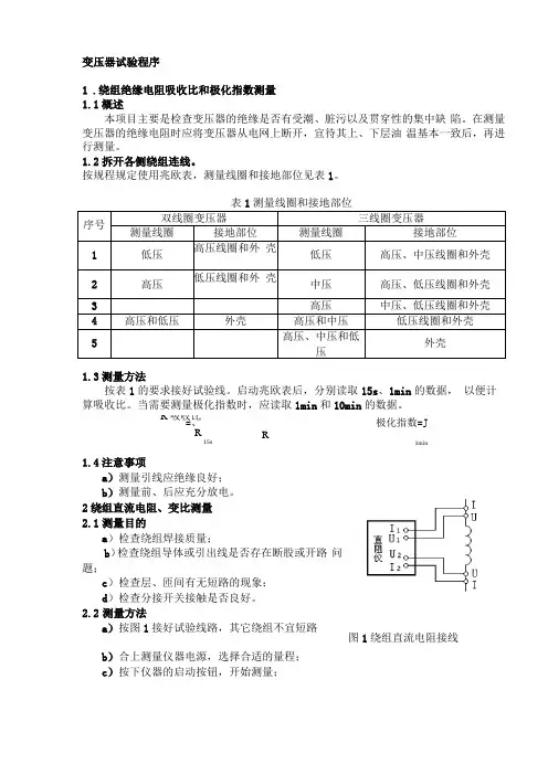
2绕组直流电阻、变比测量 2.1 测量目的a )检查绕组焊接质量;b )检查绕组导体或引出线是否存在断股或开路 问题;c )检查层、匝间有无短路的现象;d )检查分接开关接触是否良好。
2.2 测量方法a )按图1接好试验线路,其它绕组不宜短路b )合上测量仪器电源,选择合适的量程;c )按下仪器的启动按钮,开始测量;R 吸收比=、 R15s图1绕组直流电阻接线d)待仪器显示的数据稳定后,读取测量数据;e)读完数据后,按下复位或放电按钮;f)仪器放电结束后,方可进行改接线或拆线。
2.4注意事项a)测量前应记录变压器绕组温度和绝缘油温度;b)测量端子应接触良好,必要时应打磨测点表面;c)调节无载分接开关时,应来回转动几次触头,使触头接触良好;d)测量时非被测绕组不宜短路,各绕组间也不能通过接地开关与大地形成短路;e)当测量线的电流引线和电压引线分开时,应将电流引线夹于被测绕组的外侧,电压引线夹于被测绕组的内侧,如图1所示;f)试验设备应可靠接地,被试品试验完毕后充分放电。

变压器绕组变形测量仪标准说明书安全事项非专业人员请勿拆开维修,以免触电及扩大故障范围!请勿拆下仪器的盖板:以免产生电击危险警告!为避免伤害人身及设备,使用测试仪前请先阅读“安全须知”和“警告”以及“注意”等相关资料的内容。
安全须知请遵循本手册的说明使用本测试仪,否则测试仪所提供的保护可能会受到损坏。
本手册中,警告是指对使用者构成危险的情况或操作。
小心是指对测试仪或被试变压器可能造成损坏的情况或操作。
注意是指对测试结果可能造成误差的情况或操作。
安全工作准则请参阅安全须知资料,并遵循下列说明的安全工作准则。
警告、小心和注意!为了避免人身伤害,同时为避免测试仪或被试变压器受到损坏,请遵循以下准则进行操作:使用前,请先检查测试仪的外观,检查电源开关位置是否在“关”的位置、各接线端子是否正常。
测试仪的“接地”没有连接正确前,请不要开始绕组变形测试。
试验前应将被试变压器线端充分放电。
绕组变形测试应在解开变压器所有引线(包括架空线、封闭母线和电缆)的前提下进行,并使这些引线尽可能的远离变压器套管(周围接地体和金属悬浮物需离开变压器套20cm以上),尤其是与封闭母线连接的变压器。
测试时必须正确记录分接开关的位置。
应尽可能将被试变压器的分接开关放置在第1分接,特别对有载调压变压器,以获取较全面的绕组信息。
对于无载调压变压器,应保证每次测量在同一分接位置,便于比较。
变压器铁心必须与外壳可靠接地。
测试仪外壳、测量阻抗外壳必须与变压器外壳可靠接地。
应保证测量阻抗的接线钳与套管线夹紧密接触。
如果套管线夹上有导电膏或锈迹,必须使用砂布或干燥的棉布擦拭干净。
目录一、仪器概述 (3)二、主要技术特点 (4)三、主要技术参数 (5)扫描方式 (5)其他技术参数 (5)四、使用特点 (6)五、仪器使用方法 (7)仪器面板介绍 (7)变压器的几种常用检测接线方式 (7)六、三相Yn形测量接线 (8)七、三相Y形测量接线 (9)八、三相△形测量接线 (11)九、单相X、Y、Z测量接线 (12)十、测试软件界面介绍 (14)十一、测试软件使用流程 (16)十二、试验程序及注意事项 (17)十三、变压器绕组变形试验作业指导书 (17)一、仪器概述变压器绕组变形频率响应测试仪根据对变压器内部绕组特征参数的测量,采用目前世界发达国家正在开发完善的内部故障频率响应分析(FRA)方法,能对变压器内部故障作出准确判断。
PDF 文件使用 "pdfFactory Pro" 试用版本创建 Taikai Electric Group Co., Ltd is a large-scale ent erpri se of researc hi ng & devel opi ng, m anu fac t u ri ng an d s el l i ng of c om p l et e eq ui p m en t s of p ow er t ran sm i s si on and di st r i bu t i on, up t o 55 0kV as w el l as a professional EPC contractor of transmission and transformation projects. Taikai Group with 1. 55 billion yuan of registered capital and 4.60 billion yuan of total capital, occupies 450,000 square meters of building area, and has more than 6700 employees. The group subordinated wit h 12 c om panies is ranked top 3 in the switchgear line of the whole country, with its comprehensive economic targets and the No. 1 position in Shandong province. The sales revenue has reached 1.05 billion USD last year. The day after the establishment, Taikai has been actively prom oting cultrue-advancingenterprise strategy, to im prove the company core com petence, and construct “animate enterprise, well-known products, and employee with great morale” development environment. The en t erpri se s pi ri t “Honest , Credi t , Prac tic al, and Innovative” and business , object ives “Pursuing Perfect and Repay Society.” Have been to the common corporate values and philosophy. Taikai uses the advanced MIS i nform ation system, and the design and m anufacture of products adopts CAD and CAM technology. All the subordi nated fi liales have passed t he ISO9001-2008 quality managem ent system,OHSAS18001-1999 occupational health and safety managem ent system, and ISO140012004 environmental management system, and “China Compulsory Certification”certification of l ow -vol t el ec t ri c appl i anc e and P CCC c erti fic at ion of nat ional energy produc ts. According to GB/T19001:2000 international quality standard, group has established strict quality management system. Our corporation perseveres in “intensive products and sincere desire service” quality service philosophy, pursues the im provem ent of product and service quality, and devotes our attention to supplying zero-defec t product s and zerodistance highly-efficient service. Taikai insists on independent innovation and technology strengthening enterprise, and the products consist of 5 catagories: switches, switch cubicles, transformers, automatic control, and wires and cables. It covers 6 voltage levels with 550kV and below, more than 180 kinds and over 2000 models. Adheres to the sustainable development informatization, innovative and hi gh t ec hnol ogy, professi onal izat ion, and economization, the group puresues the business pol i cy of Quali t y Devel opi ng Market and Integrity Casting Brand, and devotes itself to band m anagement strategy to build “TK” band. There are more than 30 kinds of products which fill in gaps of country and province, over 20 kinds of products listed in “Chinese National Key New Products Plan and Torch Plan” and ,more than 10 kinds of products have the honour to get national pantent. In rec ent years, Taikai has been chievi ng hypernom al and striding developm ent, and awarded as nationalwide “Key High and New Tech Enterprises” “Nationalwide Torch Plan , Key Enterprise of Tai’an Transm ission and Transformation Products Manufacture Base” , “Nationalwide Enterprise Adhering to Heavy Credi t of Cont ract s” , “Nat ional Model Harmonious Enterprise in Labor Relation” one , of the fifty powerful enterprises in paying taxes by mechanical industry of Shandong province, one of the ten prop enterprises in economy of Tai’an city, the “civilized unit” by Shandong prov i nc e for c ont i nu ous fou r years, t he advanced unit i n m aki ng peopl e ric h and vitalizing Shandong province. According to the category of transmission and t rans for m at i on eq ui p m ent s , Tai k ai has establ ished 12 w holly-owned subsidiaries, which are all enterprises above designated size. Standing one the area of over 1,333, 333m 2 , with the professional and dedicated at t i t u d e, Tai k ai p eo p l e s p eed u p t h e development step of these 12 companies. W e are trying our best to promote“Taikai” from equipment m anufacture to overall design and installation of substations, and the dom estic l eadi ng and i nt ernat i onal advanc ed transmission and transformation manufacture base.Enterprise Spirit: Honest, Credit, Practical, and Innovative Enterprise Tenet: Pursuing perfect to repay society Operation Principle: Maintaining the domestic leading position, and Achieve world top-ranking Quality Policy: For all the positions, prevention should come first, and improve the quality management system continuously. To provide the electric system excellent product with better performance, quality and price to make more contributes to the society.PDF 文件使用 "pdfFactory Pro" 试用版本创建 Shandong Taikai Power Engineering Co., Ltd (hereinafter briefed as TKPE), subordinated to Taikai Electric Group, is an economic entity of independent corporation, and enjoys right in foreign trade & power engineering business. TKPE is the leading company in supplying complete equipments for high-volt power transmission and transformation substation, including: Transformer, GIS, Circuit Breaker, Disconnector, Current Transformer, Voltage Transformer, Switch Cubicle, Prefabricated Substation, and Integrated Protection Devices. TKPE is an EPC c ontractor of power transmission and transformation substation projects and the incorporated facilities for thermal station, hydropower station and combined cycle power station and the supplying of professional international trade service, which is approved by China Ministry of Construction. TKPE possesses credential of import and export enterpris, economic cooperation concerning foreign interests, and construction permit of contracting installation, maintenance, and commission. TKPE adopts firs t-c las s engineer management technology, internal computer network, internet, CAD drawing software and comprehensive management software. “TK” brand complete products, reputable all over the world, have been exported to Poland, Russia, Sudan, Vietnam, Myanmar, Turkey, Pakistan, Kazakhstan, Mongolia, Nigeria, Algeria, Nepal, India and etc. TKPE would establish and perfect the quality control and internal management system for a project under the condition of guarantying the quality and reliability of the equipment to meet customer’s requirements in safety, sanitary, environment protection, risk control and etc. TKPE sincerely wishes to cooperate with y ou f or m u t ual b en ef it an d f u r th er development, we promise to provide you qualified product and considerate service.PDF 文件使用 "pdfFactory Pro" 试用版本创建 TRANSFORMER10~35kV Oil-immersed Power Transformer SC(B) Serial Epoxy Casting Dry Transformer SCBZ9-315~2500/10 Serial Epoxy Casting Dry Transformer with OLTCINSTRUMENT TRANSFORMER1 7LVQB-35~500 Series SF6 Current Transformer Oil-immersed Vertical Current Transformer LVB(T)-35~220 Oil-immersed Inverted Current Transformer51 54 57 60 63 65 67 68 6912 13JDQXF-35~220 Voltage Transformer TYD-35~220 Capacitor Voltage Transformer JLSQ-10(35) Combined Transformer Metallic Oxide Lightning Arrester Compound-Bushing Zero-Clearance LA Porcelain Bushing LASG10 Type-H Insulating Dry TransformerSCBH10 Series Amorphous Alloy Dry Type Transformer15 35~500kV Oil-immersed Power Transformer Commutator Transformer17 28 29Furnace TransformerREACTORBKGKL Shunt Reactor30 32 41 46 48 50CKGKL Dry-type Air-lore Reactor XKGKL Current Limiting Reactor Dry-type core Reactor LKGKL Filter Reactor 330kV,550kV Oil-Immersed ReactorPDF 文件使用 "pdfFactory Pro" 试用版本创建 10~35kVOil-immersed Power Transformer1 OverviewThis product applies to 3-phases, 50Hz, 35kV and below power system, and is the main transformation equipment of small and medium enterprise. The product has widely used in agricultural and industrial power distribution, power and lighting. The company draw on advanced technology, using new materials and optimized design to make the products more reasonable, the electric strength, mechanical strength, and heat dissipation capacity of the product to be significantly improved. The product meets GB1094.1~2-1996, GB1094.3~4-2003, GB/T6451-1999.2 Model and DefinitionsS(F)Z □-M- □/ □ Rated voltage (kV) Rated power (kVA) Full seal Design series no. On-load switch Cooling method (air cooling) Number of phase (three phases)3 Service and Installation ConditionsAltitude:≤1000m Environment temperature:The maximum temperature:+40℃,the maximum monthly average temperature:+30℃,the maximum yearly average temperature:+20℃,The lowest temperature:-45℃ (3) Power demand:approximate sine wave, three-phase symmetrical (4) Installation site:outside or inside, the environment has no significant contamination Note: it should be explained if the transformer is used in special conditions in order.4 Main ParametersS9 serial 35kV oil-immersed power transformer with OCTCVoltage group and tap Type S9-50 S9-80 S9-100 S9-125 S9-160 S9-200 S9-250 S9-315 S9-400 S9-500 S9-630 S9-800 S9-1000 S9-1250 S9-1600 S9-2000 S9-2500 35 38.5 ± 5% or 0.4 Yyn0 or Dyn11 HV HV tap LV Vector No load group loss 0.21 0.28 0.29 0.34 0.36 0.43 0.51 0.61 0.73 0.86 1.04 1.23 1.44 1.76 2.12 2.65 2.96 Load loss 1.27/1.21 1.81/1.72 2.12/2.02 2.5/2.38 2.97/2.83 3.5/3.33 4.16/3.96 5.01/4.77 6.05/5.76 7.28/6.93 8.28 9.90 12.15 14.67 17.55 20.7 24.5 No load Short-circuit Weight current impedance 2.0 1.8 1.8 1.70 1.60 1.50 1.40 1.30 1.30 1.20 1.10 1.00 1.00 0.90 0.80 0.70 0.60 6.5 900 1020 1100 1220 1320 1580 1780 1795 2230 2460 2970 3595 4010 4795 5760 6000 6830 Dimension (mm) L 1220 1220 1220 1220 1810 1990 2010 2020 2020 2040 2320 2365 2390 2470 2660 2670 2500 W 950 1070 1070 1250 1020 1020 1120 1120 1200 1220 1190 1510 1520 1530 1600 1650 3000 H 1710 1770 1800 1900 1930 2080 2130 2200 2290 2400 2410 2365 2425 2610 2650 2730 2700 1070 × 1070 820 × 820 660 × 660 Gauge(mm)± 2 × 2.5% 0.69Note: (1) For the transformer capacity of 500kVA and below, the load loss values of table slash top apply to Dyn11 vector group, the load loss values of table bottom apply to Yyn0 vector group. (2) Dimensions only for reference. (3) Making special parameter power transformer according to customer’s demand.P 1.PDF 文件使用 "pdfFactory Pro" 试用版本创建 S11 type 35kV oil-immersed power transformer with OCTCVoltage group and tapTypeHVHV tapLVVector No load group loss 0.17 0.22 0.24 0.27 0.29 0.34 0.41 0.49 0.58 0.69 0.83 0.98 1.15 1.41 1.7 1.98 2.35Load loss 1.21/1.15 1.72/1.63 2.01/1.92 2.38/2.26 2.82/2.69 3.33/3.16 3.95/3.76 4.76/4.53 5.75/5.47 6.92/6.58 7.87 9.41 11.54 13.94 16.68 19800 23000No load Short-circuit Weight current impedance 1.6 1.44 1.44 1.36 1.28 1.2 1.12 1.04 1.04 0.96 0.88 0.80 0.80 0.72 0.64 0.56 0.48 6.5 785 920 1100 1245 1470 1510 1615 2010 2170 2565 2980 3680 4490 4860 5580 6090 6900Dimension (mm)L W HGauge(mm)S11-50 S11-80 S11-100 S11-125 S11-160 S11-200 S11-250 S11-315 S11-400 S11-500 S11-630 S11-800 S11-1000 S11-1250 S11-1600 S11-2000 S11-2500 35 ± 5% or 0.4 38.5 ± 2 × 2.5% 0.69 Yyn0 or Dyn111070 1090 1165 1265 1310 1350 1400 1640 1720 2030 2070 2220 2370 2390 2430 2550 2630830 850 900 1080 1080 1100 1120 1130 1140 1160 1220 1260 1290 1340 1420 1700 18001770 1790 1870 1950 1970 1980 2040 2080 2120 2160 2240 2340 2440 2580 2620 2700 3050 1070 × 1070 820 × 820 660 × 660(1) For the transformer capacity of 500kVA and below, the load loss values of table slash top apply to Dyn11 vector group, the load loss values of table bottom apply to Yyn0 vector group. (2) Dimensions only for reference. (3) Making special parameter power transformer according to customer’s demand. S9 type 10kV oil-immersed power transformer with OCTCVoltage group and tapTypeHVHV tapLVVector No load group loss 0.13 0.17 0.20 0.25 0.29 0.34 0.40Load loss 0.63/0.60 0.91/0.87 1.09/1.04 1.31/1.25 1.58/1.50 1.89/1.80 2.31/2.20 2.73/2.60 3.20/3.05 3.83/3.65 4.52/4.30 5.41/5.15 6.20 7.50 10.3 12.0 14.5 19.8 23.0No load Short-circuit Weight current impedance 2.3 2.0 1.9 1.9 1.8 1.7 1.6 1.5 1.4 1.4 1.3 1.2 1.1 1.0 1.0 0.9 0.8 0.7 0.6 4.0 320 400 440 490 560 670 770 920 1110 1260 1550 1780 2240 2495 2930 3380 4090 5280 6370Dimension (mm)L W HGauge(mm)S9-30 S9-50 S9-63 S9-80 S9-100 S9-125 S9-160 S9-200 S9-250 S9-315 S9-400 S9-500 S9-630 S9-800 S9-1000 S9-1250 S9-1600 S9-2000 S9-2500 6 6.3 10 11 Yyn0 ± 5% or 0.4 or Dyn111050 1100 1110 1110 1110 1190 1250 1250 1540 1560 1600 1630 1760 2135 2140 2200 2380 2420 2460610 770 770 780 790 800 830 840 990 1010 1040 1200 1230 1250 1370 1370 1385 1450 27001080 1120 1150 1210 1220 1370 1400 1440 1500 1530 1590 1650 1760 1835 1945 1990 2080 2405 2600 1070 × 1070 820 × 820 660 × 660 550 × 550 400 × 4000.48 0.56 0.67 0.80 0.96 1.20 1.40 1.70 1.95 2.40 2.60 3.000.69 10.5 ± 2 × 2.5%Note: (1) For the transformer capacity of 500kVA and below, the load loss values of table slash top apply to Dyn11 vector group, the load loss values of table bottom apply to Yyn0 vector group. (2) Dimensions only for reference. (3) Making special parameter power transformer according to customer’s demand.P 2.PDF 文件使用 "pdfFactory Pro" 试用版本创建 SZ9 type 10kV oil-immersed power transformer with OLTCVoltage group and tap Type SZ9-100 SZ9-125 SZ9-160 SZ9-200 SZ9-250 SZ9-315 SZ9-400 SZ9-500 SZ9-630 SZ9-800 SZ9-1000 SZ9-1250 SZ9-1600 6 6.3 10 10.5 11 ± 4 × 2.5%0.4 0.69HVHV tapLVVector No load group loss 0.29 0.34 0.40 0.48 0.56 Yyn0 or Dyn11 0.67 0.80 0.96 1.20 1.40 1.70 1.95 2.40Load loss 1.58 1.89 2.31 3.06 3.6 4.32 5.22 6.21 7.65 9.36 10.98 13.05 15.57No load Short-circuit Weight current impedance 1.8 1.7 1.6 1.5 1.4 1.4 1.3 1.2 1.1 1.0 1.0 0.9 0.8 4.5 4.0 880 960 1080 1200 1400 1600 1870 2190 2620 3100 3660 4160 4880Dimension (mm)L W HGauge(mm)1630 1660 1710 1740 1940 1980 2050 2060 2590 2620 2650 2720 2880800 850 870 870 880 900 1000 1070 1130 1290 1380 1410 14901370 1380 1410 1450 1560 1610 1680 1760 1970 2070 2120 2190 2210 820 × 820 660 × 660Note: (1) Above parameter applies to 400V of LV. (2) Dimensions only for reference. (3) Making special parameter power transformer according to customer’s demand.S9-M type 10kV oil-immersed power transformer with OCTCVoltage group and tapTypeHVHV tapLVVector No load group loss 0.13 0.17 0.20 0.25 0.29 0.34 0.40Load loss 0.63/0.60 0.91/0.87 1.09/1.04 1.31/1.25 1.58/1.50 1.89/1.80 2.31/2.20 2.73/2.60 3.20/3.05 3.83/3.65 4.52/4.30 5.41/5.15 6.20 7.50 10.3 12.0 14.5 19.8 23.0No load Short-circuit Weight current impedance 2.3 2.0 1.9 1.9 1.8 1.7 1.6 1.5 1.4 1.4 1.3 1.2 1.1 1.0 1.0 0.9 0.8 0.7 0.6 4.5 4.0 360 440 480 530 600 680 790 900 1080 1250 1500 1700 2180 2395 2850 3370 4060 5160 6390Dimension (mm)L W HGauge(mm)S9-M-30 S9-M-50 S9-M-63 S9-M-80 S9-M-100 S9-M-125 S9-M-160 S9-M-200 S9-M-250 S9-M-315 S9-M-400 S9-M-500 S9-M-630 S9-M-800 S9-M-1000 S9-M-1250 S9-M-1600 S9-M-2000 S9-M-25006 6.3 10 10.5 11820 870 880 900 910 950 990 1250 1280 1370 1440 1440 1600 1715 1910 1980 1980 2100 2180670 670 670 680 690 700 720 730 750 780 810 820 860 960 1250 1280 1280 1450 1490990 1030 1060 1120 1170 1190 1210 1320 1380 1400 1470 1530 1570 1585 1700 1740 1830 2020 2230 1070 × 1070 820 × 820 660 × 660 550 × 550 400 × 400Yyn0± 5% or ± 2× 2.5% 0.4 0.690.48 0.56 0.67 0.80 0.96 1.20 1.40 1.70 1.95 2.40 2.60 3.00or Dyn11Note: (1) For the transformer capacity of 500kVA and below, the load loss values of table slash top apply to Dyn11 vector group, the load loss values of table bottom apply to Yyn0 vector group. (2) Dimensions only for reference. (3) Making special parameter power transformer according to customer’s demand.P 3.PDF 文件使用 "pdfFactory Pro" 试用版本创建 S11 type 10kV oil-immersed power transformer with OCTCVoltage group and tapType S11-30 S11-50 S11-63 S11-80 S11-100 S11-125 S11-160 S11-200 S11-250 S11-315 S11-400 S11-500 S11-630 S11-800 S11-1000 S11-1250 S11-1600 S11-2000 S11-2500 6 6.3 10 10.5 11HVHV tapLVVector No load group loss0.10 0.13 0.15 0.18 0.20 0.24 0.28Load loss0.63/0.60 0.91/0.87 1.09/1.04 1.31/1.25 1.58/1.50 1.89/1.80 2.31/2.20 2.73/2.60 3.20/3.05 3.83/3.65 4.52/4.30 5.41/5.15 6.20 7.50 10.3 12.0 14.5 19.8 23.0No load Short-circuit Weight current impedance1.84 1.6 1.52 1.52 1.44 1.36 1.28 1.20 1.12 1.12 1.04 0.96 0.88 0.8 0.8 0.72 0.64 0.56 0.48 4.5 4.0 320 410 470 510 570 700 800 950 1080 1290 1530 1800 2330 2680 3130 3650 4430 4730 6100Dimension (mm)L 1050 1100 1110 1110 1110 1190 1250 1250 1540 1560 1460 1520 1740 2120 2170 2340 2470 2130 2270 W 610 770 770 780 790 800 830 830 990 1010 1030 1190 1230 1240 1420 1450 1510 1710 2100 H 1080 1150 1180 1230 1240 1410 1430 1490 1510 1580 1600 1670 1840 1940 2010 2040 2290 2550 2600Gauge(mm)400 × 400Yyn0 ± 5%or ± 2× 2.5%0.4 0.690.34 0.40 0.48 0.57 0.68 0.81 0.98 1.15 1.36 1.64 1.98 2.35550 × 550or Dyn11660 × 660820 × 820Note: (1) For the transformer capacity of 500kVA and below, the load loss values of table slash top apply to Dyn11 vector group, the load loss values of table bottom apply to Yyn0 vector group. (2) Dimensions only for reference. (3) Making special parameter power transformer according to customer’s demand. S11-M type 10kV oil-immersed power transformer with OCTCVoltage group and tapTypeHVHV tapLVVector No load group loss 0.10 0.13 0.15 0.18 0.20 0.24Load loss 0.63/0.60 0.91/0.87 1.09/1.04 1.31/1.25 1.58/1.50 1.89/1.80 2.31/2.20 2.73/2.60 3.20/3.05 3.83/3.65 4.52/4.30 5.41/5.15 6.20 7.50 10.3 12.0 14.5No load Short-circuit Weight current impedance 1.84 1.6 1.52 1.52 1.44 1.36 1.28 1.20 1.12 1.12 1.04 0.96 0.88 0.8 0.8 0.72 0.64 4.5 4.0 360 485 500 540 610 710 810 960 1050 1280 1430 1690 2270 2580 3060 3560 4470Dimension (mm)L W HGauge(mm)S11-M-30 S11-M-50 S11-M-63 S11-M-80 S11-M-100 S11-M-125 S11-M-160 S11-M-200 S11-M-250 S11-M-315 S11-M-400 S11-M-500 S11-M-630 S11-M-800 S11-M-1000 S11-M-1250 S11-M-1600 6 6.3 10 10.5 11 ± 5%or ±2× 2.5% 0.4 0.69 Yyn0 or Dyn11820 870 880 900 910 950 990 1030 1320 1370 1410 1440 1580 1700 1840 1980 2000670 670 670 680 690 700 720 730 750 780 790 800 870 960 1220 1330 1340990 1060 1090 1140 1180 1220 1240 1310 1330 1400 1420 1490 1650 1690 1760 1790 1910 820 × 820 660 × 660 550 × 550 400 × 4000.28 0.34 0.40 0.48 0.57 0.68 0.81 0.98 1.15 1.36 1.64Note: (1) For the transformer capacity of 500kVA and below, the load loss values of table slash top apply to Dyn11 vector group, the load loss values of table bottom apply to Yyn0 vector group.(2) Dimensions only for reference.(3) Making special parameter power transformer according to customer’s demand.P 4.PDF 文件使用 "pdfFactory Pro" 试用版本创建 S11-M.R serial 10kV oil-immersed power transformer with OCTCVoltage group and tapTypeHVHV tapLVVector No load group loss 0.10 0.13 0.15 0.18Load loss 0.60 0.87 1.04 1.25 1.50 1.80 2.20 2.60 3.05 3.65 4.30 5.10 6.20No load Short-circuit Weight current impedance 1.00 0.90 0.80 0.70 0.60 0.60 0.55 0.55 0.50 0.50 0.45 0.45 0.40 4.5 4.0 350 440 510 550 650 730 810 960 1110 1310 1630 1880 2280Dimension (mm)L W HGauge(mm)S11-M.R-30 S11-M.R-50 S11-M.R-63 S11-M.R-80 S11-M.R-100 S11-M.R-125 S11-M.R-160 S11-M.R-250 S11-M.R-315 S11-M.R-400 S11-M.R-500 S11-M.R-630 6 6.3 10 11 ± 5%or ± 2 × 2. 5% 0.4 0.69 Yyn0 or Dyn111040 1080 1110 1130 1150 1180 1200 1250 1310 1390 1460 1490 1580640 640 650 660 660 670 680 700 720 770 800 810 840990 1050 1100 1150 1210 1250 1280 1390 1420 1480 1550 1620 1700 660 × 660 550 × 550 400 × 4000.20 0.24 0.27 0.33 0.40 0.48 0.57 0.68 0.81S11-M.R-200 10.5Note: (1) Above parameter applies to 400V of LV. (2) Dimensions only for reference. (3) Making special parameter power transformer according to customer’s demand.SH11-M serial 10kV oil-immersed power transformer with OCTCVoltage group and tapTypeHVHV tapLVVector No load group loss 0.033 0.043 0.060 0.075 0.085 0.100Load loss 0.60 0.87 1.25 1.50 1.80 2.20 2.60 3.05 3.65 4.30 5.10 6.20 7.50 10.3 12.0 14.5 17.4No load Short-circuit Weight current impedance 1.50 1.40 1.20 1.10 1.00 0.90 0.90 0.80 0.80 0.70 0.70 0.60 0.60 0.50 0.40 0.40 0.40 5.5 4.5 4.0 480 620 800 880 955 1095 1240 1450 1680 2070 2330 2800 3340 3555 4270 4860 6160Dimension (mm)L W HGauge(mm)SH11-M-30 SH11-M-50 SH11-M-80 SH11-M-100 SH11-M-125 SH11-M-160 SH11-M-200 6 ± 5%or ±2× 2.5% 0.4 0.69 Dyn11 SH11-M-250 6.3 SH11-M-315 10 SH11-M-400 10.5 SH11-M-500 11 SH11-M-630 SH11-M-800 SH11-M-1000 SH11-M-1250 SH11-M-1600 SH11-M-2000885 1215 1310 1320 1360 1410 1465 1540 1580 1705 1655 1840 1950 2110 2290 2040 2330780 830 840 885 920 910 910 910 910 945 1000 1140 1170 1250 1370 1410 16501005 1035 1125 1060 1095 1140 1200 1240 1300 1360 1400 1415 1485 1420 1530 1560 1680 1070 × 1070 820 × 900 660 × 660 550 × 6600.120 0.140 0.170 0.200 0.240 0.320 0.380 0.450 0.530 0.630 0.750Note: (1) Above parameter applies to 400V of LV. (2) Dimensions only for reference. (3) Making special parameter power transformer according to customer’s demand.P 5.PDF 文件使用 "pdfFactory Pro" 试用版本创建 5 Structure and FeaturesCore:the core lamination made from high permeability sheet is cutted on GEORG-line imported from Germany, using step-by-step lapped joint and colligating structure, and meets the demand of low no load loss and low noise level. Winding:using low resistivity oxygen-free copper, and linking the reasonable transposition of the parallel wire, load loss of transformer is greatly reduced. Tank:using barrel structure and large corrugated. The company adopts the technology of carbon dioxide protection, selects sealing material perfectly, machines the seal surface and carries on a strict leak detection procedure. All these assure that the transformer are leakage-free. The new style radiators and coolers improve external appearance quality of transformer greatly. Surface treatment and coating: fine processing to the oil tank surface and using special anti-fouling paint, all these assure that the surface coating does not fall off, and the steel structure does not rust away.6 Outline and Installation Size1.Oil level indicator 2.High voltage bushing 3.LV bushing 4.OCTC 5.LV neutral bushing 6.Pressure relief valve 10kV Oil-immersed Power TransformerP 6.PDF 文件使用 "pdfFactory Pro" 试用版本创建 SC(B) Serial Epoxy Casting Dry Transformer1 OverviewThis serial epoxy casting dry transformer uses high-quality materials, scientific formula and advanced technology. The product has high reliability and long life characteristics. It can be configured with different levels of protection, or does not configure the shell casing depending on the use of the environment. It applies to high-rise buildings, commercial centers, airports, tunnels, chemical plants, nuclear power plants, ships and other important or special place. Using dry-type transformers proprietary technology and casting stress control technology, controlling casting dry-type transformers internal insulation in the best condition, ensures key performance of dry-type transformers. The product calculated field strength during the design process. Make the various components field strength to 75% or less of insulating materials by adjusting the relevant parameters and ensure the product's advanced technical performance. Leading rated performance to relevant links in advance during the product design, so that the product design inputed has included relevant requirements and made the output meet the need.2 Model and DefinitionsS C(B)□ - □ / □Voltage class (kV) Rated capacity (kVA) Design series no. Opal winding circles Castresin type transformer Three-phase transformer3 Service and Installation ConditionsAltitude:1000m Environment temperature The maximum temperature:+40 The maximum monthly average temperature:+30 The maximum yearly average temperature:+20 The lowest yearly temperature:-5 Power voltage waveform: power voltage waveform approximate sine. The symmetry of multi-phase power voltage: connected power voltage of multi-phase transformershould be approximately symmetrical. Protection class:IP00, IP20, IP23. Cooling style:air cold and forced air-cooled Note: it should be explained if the transformer is used in special conditions in order.4 Main ParametersThe core using high-quality cold-rolled silicon steel sheet, 45 degrees inclined ladder joint structure, and cutting processes, the core for curing and surface with the insulating resin sealing process. HV coil using high-quality F insulating copper wire and internationally advanced insulation materials, and the large capacity coil equipped with cooling along the axial airway. LV coil using foil structure, the coil end sealed curing resin after winding, avoiding variety of foreign matter and moisture to enter. Safety, anti-fire, no pollution, it can be directly run the load center.P 7.PDF 文件使用 "pdfFactory Pro" 试用版本创建 Using Germany HTT technical, high mechanical strength, and high anti-short-circuit capability. Partial discharge is small. High thermal stability, high reliability and long service life. Low loss, low noise, energy-saving effect obviously, and maintenance-free. Good moisture-proof performance, and adapt to high humidity and other harsh environments running. Equipped with improved temperature detection and protection systems. Small size, light weight, occupies less space, and lower installation costs. SC10-5~100/10 serial epoxy casting dry transformer SC(B)9-125~2500/10 serial epoxy casting dry transformer SC(B)10-125~2500/10 serial epoxy casting dry transformer SC(B)9-30~2500/35 serial epoxy casting dry transformer.5 Outline DimensionsSC10-5~100/10 epoxy casting dry transformerOutline Dimensions Type SC10-5/10 SC10-10/10 SC10-15/10 SC10-20/10 SC10-25/10 SC10-30/10 SC10-50/10 SC10-63/10 SC10-80/10 SC10-100/10 a 515 515 575 575 585 585 585 785 785 855 b 400 400 400 400 400 400 400 500 500 500 c 300 300 400 400 400 400 400 400 400 550 d 300 300 300 300 300 300 300 400 400 400 j 175 175 195 195 200 205 210 265 265 290 h 540 550 550 550 580 580 655 800 800 860 k 100 100 110 110 110 110 110 100 100 150a:ontic length b:ontic width c:ontic landscape interface dimension d:ontic Longitudinal installation dimensions j:mo k The LV outgoing line spacing distance h: this data is outer dimension for normal product,which will alter if ording data changes,Parties through consultation. Reference SpecificationsRated Power (kVA) 30 50 63 80 100 H.V(kV) 6 6.3 6.6 10 10.5 11 Voltage Combination Tapping Range L.V(kV) Connection Symbol Short circuit No-Load impedance Loss (%) (W) 220 ± 5% ± 2 × 2.5% 0.4 Y yn0 D yn11 310 4 380 410 450 Load Losses 75℃(W) 650 920 1050 1270 1450 Load Losses 120℃(W) 750 1060 1202 1460 1670 No-Load Current (%) 2 1.5 1.5 1.1 1.1 LPA Noise Level (dB) 45 45 46 46 46 Weight (kg) 225 300 470 500 620P 8.PDF 文件使用 "pdfFactory Pro" 试用版本创建 SC(B)9-125~2500/10 Epoxy Casting Dry TransformerType SC(B)9-125/10 SC(B)9-160/10 SC(B)9-200/10 SC(B)9-250/10 SC(B)9-315/10 SC(B)9-400/10 SC(B)9-500/10 SC(B)9-630/10 SC(B)9-630/10 SC(B)9-800/10 SC(B)9-1000/10 SC(B)9-1250/10 SC(B)9-1600/10 SC(B)9-2000/10 SC(B)9-2500/10 Outline Dimensions c d 550 550 550 660 660 660 660 660 660 660 820 820 820 820 820 550 550 550 550 720 720 720 720 720 720 820 820 1070 1070 1070 Shield cap m 550 550 660 660 660 660 660 660 660 820 820 820 820 820 820a 990 1050 1100 1140 1180 1220 1240 1270 1400 1400 1460 1570 1720 1800 1950b 650 650 650 650 820 820 820 820 820 820 920 920h 1050 1080 1130 1150 1250 1300 1350 1410 1400 1460 1580 1620 1860 2050 2200A 1550 1550 1550 1550 1550 1550 1700 1700 1700 1700 1800 1950 2000 2100 2400B 1200 1200 1200 1200 1200 1200 1300 1300 1300 1300 1400 1400 1500 1500 1500n 1150 1150 1150 1150 1150 1150 1250 1250 1250 1250 1350 1350 1450 1450 1450H 1800 1800 1800 1800 1800 1800 1900 1900 1900 1900 1900 2000 2200 2400 26001200 1270 1270a:ontic length b:ontic width c:ontic landscape interface dimension d:ontic Longitudinal installation dimensions h:ontic height, A:outskin’s length, B: outskin’s width, m:outskin’s landscape interface dimension, n:outskin’s Longitudinal interface dimension, H:outskin’s heightReference SpecificationsRated Power (kVA) 125 160 200 250 315 400 500 630 630 800 1000 1250 1600 2000 2500 6 6.3 6.6 10 10.5 11 6 ± 5% ± 2 × 2.5% 0.4 Y yn0 D yn11 4 Voltage Combination Short circuit Load No-Load Connection Losses impedance Tapping Loss (W) H.V.(kV) L.V(kV) Symbol 75℃(W ) (%) Range 530 170 610 700 810 990 1100 1300 1500 1460 1700 1990 2350 2750 3400 4000 1960 2330 2540 3200 3680 4500 5420 5500 6427 7510 8960 10829 13360 15870 Load No-Load LPA Noise Weight Current Losses Level (dB) (Kg) (%) 120℃(W ) 1960 2250 2680 2920 3670 4220 5170 6220 6310 7360 8610 10260 12400 15300 18180 1 0.9 0.9 0.9 0.8 0.8 0.7 0.6 0.6 0.5 0.5 0.4 0.4 0.3 0.3 46 46 47 48 48 49 49 49 50 51 52 53 54 55 56 650 850 870 1100 1400 1550 1700 2200 2300 2500 2900 3550 4600 5500 6200P 9.PDF 文件使用 "pdfFactory Pro" 试用版本创建 。

变压器检修作业指导书目录一、适用范围 (3)二、引用标准 (3)三、天气及作业现场要求 (3)四、检修管理流程 (4)五、“三措”基本要求 (5)六、标准化作业流程 (9)七、工器具、材料 (11)八、主变压器大修工艺、质量标准 (15)九、大修报告 (25)一、适用范围本指导书适用于电压等级在35kV~220kV的国产油浸式主变、6kV及以上厂用变压器和同类设备的大修(吊罩或吊芯),对国外进口的油浸式变压器及同类设备、全密封变压器可参照本指导书执行。
二、引用标准1、GB1094.1~1094.5-85 电力变压器2、GB6451.1~6451.5-86 油浸式电力变压器技术参数和要求3、GB7665-87 变压器油4、DL/T 573-95 电力变压器检修导则5、DL/T 574-95 有载分接开关运行维护导则6、DL/T 572-95 电力变压器运行规程7、DL/T 596-1996 电力设备预防性试验规程三、天气及作业现场要求1、主变大修天气要求:①放附件油(油枕、散热器、连管等)、放油至上夹件:天气状况良好(晴)②主变吊罩(或器身):天气晴朗,器身暴露在空气中的时间应不超过如下规定:相对温度≤65%为16h;相对温度≤75%为12h2、主变大修作业现场要求:应选在无尘飞扬及其它无污染的晴天进行。
使用的工器具、设备、材料按定制图摆放整齐,方便使用,随时保持现场清洁、卫生。
四、检修管理流程五、“三措”基本要求1、组织措施作业人员职责分工施工总负责人:负责工程现场工作总的管理、指挥和协调工作负责人:负责组织施工前的现场查勘,履行开竣工手续,作业人施工过程中的安全监护,施工工器具、设备、材料的准备工作,施工人员的组织,按施工进度进行每日工作安排,协助工程施工总负责人协调、管理现场工作工程技术负责人:负责大修前主变历史资料的收集,协调工程组长、副组长进行状态诊断,作出大修方案,协调、解决现场工作所遇到的技术性问题,指导现场施工工程安全负责人:负责监督作业人员按安全规程作业,纠正违规,对违规人员进行安全思想教育,检查现场安全措施是否完善工程起吊负责人:负责检查吊绳、吊具、被吊物的绑扎,起吊的指挥其他工作项目负责人(高压试验、化学试验、电测热工、物资运输、物资组织、引下线改搭):按施工进度进行相关工作,服从工作负责人的现场指挥、协调,负责相关所辖工作范围工作人员的安全监护,编制相关调试报告工作人员:在各项目工作负责人的安排下按规程、规定、工艺要求进行工作2、安全措施1、在工程进行具体施工前,组织全部施工人员进行安全学习,反习惯性违章的学习和开工前的动员会,交代好各方面的安全措施等。

伺服电机技术解答三相交流永磁同步伺服电机简称交流伺服电机(AC server motor)或伺服电机,由于它具有高响应、高精度、运行平稳、恒转矩输出、能过载、低噪声、结构简介、可靠性高、免维护等优点,是目前旋转电机中最佳的控制电机。
本章以EDB驱动器和其配套伺服电机为例,简述伺服电机在应用中的有关问题及注意事宜,其原则和方法同样适用于其它型号的驱动器配伺服电机。
伺服电机选型:伺服电机的选型是多个因素综合考虑、合理选择的过程,一般应着重注意这几个参数的选择:电机的额定转矩、电机运行的最高转速、负载惯量及电机转子惯量、加减速时所需要的过载能力、电机起停频率等。
通过机械传动机构加在电机上的负载有二种,即负载转矩和负载惯量。
负载转矩如由下图运动方式形成:则:图中Ta为因加速时间t1形成的加速转矩,Tb为由于减速时间t3形成的制动转矩,Tf 为在t2时间内产生的负载转矩,T0为在停止时间t4产生的锁定转矩,n为工作时电机的转速。
Ta、Tb、Tf、T0、n均为通过机械传动装置折算到电机轴上的参数。
Ta、Tb可参见下式确定:式中:Jm—电机转子惯量(),Jl—折算到电机轴上的负载惯量(),t单位:sec,n单位:rpm,Ta、Tf单位:Nm。
由下式确定一个周期电机转矩的均方根值:确定预选电机的额定转矩大于Trms值;确定预选电机的额定转速大于实际运行的最高转转速;其过载转矩大于Ta、Tb中最大值,即可选定伺服电机。
加在电机轴上的负载惯量,对伺服电机的灵敏度及快速移动、精确定位有很大的影响。
较大的负载惯量,当指令速度发生变化时,电机达到指令速度的时间会较长;多轴同时运动时,会使形成的轨迹偏离指令轨迹过大,造成较大的误差。
所以,选择机械传动机械,使折算到电机轴上的负载惯量合适,是伺服电机选型中重要的过程。
机械传动不仅要满足脉冲当量、转矩(功率)放大等技术要求,更要注重负载惯量与电机的适配。
负载惯量是否与电机相适配的标准,是指负载惯量折算到电机轴上的负载惯量Jl,其数值与电机转子惯量的倍数关系。
旋转变压器( r e s o l v e r ) 原理§4—1旋转变压器旋转变压器是一种常用的转角检测元件,由于它结构简单,工作可靠,且其精度能满足一般的检测要求,因此被广泛应用在数控机床上。
一、旋转变压器的结构旋转变压器的结构和两相绕线式异步电机的结构相似,可分为定子和转子两大部分。
定子和转子的铁心由铁镍软磁合金或硅钢薄板冲成的槽状心片叠成。
它们的绕组分别嵌入各自的槽状铁心内。
定子绕组通过固定在壳体上的接线柱直接引出。
转子绕组有两种不同的引出方式。
根据转子绕组两种不同的引出方式,旋转变压器分为有刷式和无刷式两种结构形式。
图4-1是有刷式旋转变压器。
它的转子绕组通过滑环和电刷直接引出,其特点是结构简单,体积小,但因电刷与滑环是机械滑动接触的,所以旋转变压器的可靠性差,寿命也较短。
图4-1有刷式旋转变压器图4-2无刷式旋转变压器图4—2是无刷式旋转变压器。
它分为两大部分,即旋转变压器本体和附加变 压器。
附加变压器的原、副边铁心及其线圈均成环形,分别固定于转子轴和壳体 上,径向留有一定的间隙。
旋转变压器本体的转子绕组与附加变压器原边线圈连在 一起,在附加变压器原边线圈中的电信号,即转子绕组中的电信号,通过电磁耦 合,经附加变压器副边线圈间接地送出去。
这种结构避免了电刷与滑环之间的不良 接触造成的影响,提高了旋转变压器的可靠性及使用寿命,但其体积、质量、成本 均有所增加。
常见的旋转变压器一般有两极绕组和四极绕组两种结构形式。
两极绕组旋转变 压器的定子和转子各有一对磁极,四极绕组则有两对磁极,主要用于高精度的检测 系统。
除此之外,还有多极式旋转变压器,用于高精度绝对式检测系统。
旋转变压器的工作原理由于旋转变压器在结构上保证了其定子和转子 (旋转一周)之间空气间隙内磁通 分布符合正弦规律,因此,当激磁电压加到定子绕组时,通过电磁耦合,转子绕组 便产生感应电势。
图4—3为两极旋转变压器电气工作原理图。
CA08104001E For more information, visit: /consultantsSeptember 2011Sheet 13 Transformer Product Selector—Liquid-Filled Types001September 2011Sheet 13 Transformer Product Selector—Dry Types002 Table 13.0-1A. Transformer Product Selector (Continued)TransformerMaximum Voltage AvailablekVACAGTabTypes ApplicationConsiderationsPrimary SecondaryUnit Substation Transformer—Dry-TypePrimary UnitSubstation(Steps down utilityservice voltage)34.5 kV15 kV500 kV A–10 MV A13VPI—Vacuum pressureimpregnation with polyesterresin. Used in commercialconstruction and industrialapplication.VPE—Vacuum PressureEncapsulated with silicon resin.Applied where MIL-1-24092spec is required (salt-sprayapplication).Cast Coil—Uses the electricaland mechanical strengthof epoxy to provide higherlevels of performance andenvironmental protection inhigh moisture, dust-ladenand chemical environments.Windings are hermeticallysealed in epoxy.Resibloc—Coils insulatedwith epoxy and reinforcedwith roving glass fiber. Highlyresistant to short-circuit forces,severe climate conditions andcycling loads.Transformer is part of aclose-coupled assemblythat includes both primaryand secondary equipment.Explosion resistant, fireresistant and nonpollutingto the environment.SecondaryUnit Substation(Provides second-ary system voltage)34.5 kV600V112.5 kV A– 3750 kV A14Network Transformer (Spot Networks)—Dry-TypeSecondarySpot Network34.5 kV480V500 kV A–3000 kV A18VPI—Vacuum pressureimpregnation with polyesterresin. Used in commercialconstruction and industrialapplication.VPE—Vacuum PressureEncapsulated with silicon resin.Applied where MIL-1-24092spec is required (salt-sprayapplication).Cast Coil—Uses the electricaland mechanical strengthof epoxy to provide higherlevels of performance andenvironmental protection inhigh moisture, dust-ladenand chemical environments.Windings are hermeticallysealed in epoxy.Resibloc—Coils insulatedwith epoxy and reinforcedwith roving glass fiber. Highlyresistant to short-circuit forces,severe climate conditions andcycling loads.Network transformers arepart of a commercial spotnetwork system where multipletransformer units feed largepotential loads in parallel, suchas four 2500 kV A units feeding480/277 volt loads. Dry-typenetwork transformers donot have an integral switch.Network protectors are fieldmounted on the secondaryflange, or assembly mountedin switchgear sections.Installations are usuallyindoors, and multiple primarycircuits and sources that can beparalleled must exist upstream,usually supplied by the utility.Government buildings withhigh levels of loads at theutilization voltage meritthese systems.The loads are not adverselyaffected by one primarycircuit outage, and may not beaffected by two being downin four transformer spotnetwork systems.For more information, visit: /consultants CA08104001E。
Eaton 007364Eaton Moeller® series ZW7 Current transformer-operated overloadrelay, 110-160A, 1N/O+1N/CEaton Moeller® series ZW7 Currenttransformer-operated overload relay0073644015080073642162.5 mm97 mm200.5 mm0.724 kgCSA File No.: 012528CSA-C22.2 No. 14CSAULUL 508IEC/EN 60947UL File No.: E29184UL Category Control No.: NKCR VDE 0660IEC/EN 60947-4-1CSA Class No.: 3211-03CE Rated operational current: Switch-on and switch-off conditions based on DC-13, time constant as specified.Product Name Catalog NumberEANProduct Length/Depth Product Height Product Width Product Weight Certifications Catalog NotesTrip-free releaseProtection with heavy starting duty Reset pushbutton manual/auto Test/off button -25 °C50 °C25 °C40 °COtherDamp heat, constant, to IEC 60068-2-78Damp heat, cyclic, to IEC 60068-2-30IP00Separate positioningSeparate mountingAs required27 mm110 A160 AIII3ZW7 current transformer-operated overload relaysFinger and back-of-hand proof, Protection against direct contact when actuated from front (EN 50274)Features Ambient operating temperature - minAmbient operating temperature - maxAmbient operating temperature (enclosed) - minAmbient operating temperature (enclosed) - maxClassClimatic proofingDegree of protectionMounting methodMounting positionOpening diameterOverload release current setting - minOverload release current setting - maxOvervoltage categoryPollution degreeProduct categoryProtectionRated impulse withstand voltage (Uimp)8000 V AC4000 V (auxiliary and control circuits)10 g, Mechanical, Sinusoidal, Shock duration 10 ms Branch circuits, (UL/CSA)Continuous 1 x (0.75 - 2.5) mm²2 x (0.75 - 2.5) mm²1 x (0.75 - 4) mm²2 x (0.75 - 4) mm²2 x (18 - 14)8 mmM3.5, Terminal screw2, Terminal screw, Pozidriv screwdriver1 x 6 mm, Terminal screw, Control circuit cables, Standard screwdriver1.2 Nm, Screw terminals, Control circuit cables6 A 1.5 A 1.5 A 0.9 A 0.4 A 0.2 A 0.9 A With overload relay in conjunction with a transformer as required for the contactor, Max. Fuse, Main conducting pathsMax. 6 A gG/gL, Fuse, Auxiliary contacts111Shock resistanceSuitable forTemperature compensation Terminal capacity (flexible with ferrule) Terminal capacity (solid)Terminal capacity (solid/stranded AWG) Stripping length (control circuit cable) Screw sizeScrewdriver sizeTightening torqueConventional thermal current ith of auxiliary contacts (1-pole, open)Rated operational current (Ie) at AC-15, 120 VRated operational current (Ie) at AC-15, 220 V, 230 V, 240 V Rated operational current (Ie) at AC-15, 380 V, 400 V, 415 V Rated operational current (Ie) at DC-13, 110 VRated operational current (Ie) at DC-13, 220 V, 230 VRated operational current (Ie) at DC-13, 24 VRated operational current (Ie) at DC-13, 60 V Short-circuit protectionShort-circuit protection ratingNumber of auxiliary contacts (change-over contacts) Number of auxiliary contacts (normally closed contacts) Number of auxiliary contacts (normally open contacts) Number of contacts (normally closed contacts)0.75 A690 V240 V AC, Between auxiliary contacts, According to EN 61140 440 V AC, Between main circuits, According to EN 61140440 V AC, Between auxiliary contacts and main contacts, According to EN 61140R300, DC operated (UL/CSA)B300 at opposite polarity, AC operated (UL/CSA)B600 at opposite polarity, AC operated (UL/CSA)600 VAC600 VAC 16.3 W0 W2.1 W160 A0 WMeets the product standard's requirements.Meets the product standard's requirements.Meets the product standard's requirements.Meets the product standard's requirements.Meets the product standard's requirements.Does not apply, since the entire switchgear needs to be evaluated.Does not apply, since the entire switchgear needs to be evaluated.Meets the product standard's requirements.Does not apply, since the entire switchgear needs to be evaluated.Rated operational voltage (Ue) - maxSafe isolationSwitching capacity (auxiliary contacts, pilot duty) Voltage rating - maxVoltage rating - max Number of contacts (normally open contacts)Equipment heat dissipation, current-dependent PvidHeat dissipation capacity PdissHeat dissipation per pole, current-dependent PvidRated operational current for specified heat dissipation (In) Static heat dissipation, non-current-dependent Pvs10.2.2 Corrosion resistance10.2.3.1 Verification of thermal stability of enclosures10.2.3.2 Verification of resistance of insulating materials to normal heat10.2.3.3 Resist. of insul. mat. to abnormal heat/fire by internal elect. effects10.2.4 Resistance to ultra-violet (UV) radiation10.2.5 Lifting10.2.6 Mechanical impact10.2.7 Inscriptions10.3 Degree of protection of assemblies10.4 Clearances and creepage distancesMeets the product standard's requirements.Does not apply, since the entire switchgear needs to beevaluated.Does not apply, since the entire switchgear needs to be evaluated.Is the panel builder's responsibility.Is the panel builder's responsibility.Is the panel builder's responsibility.Is the panel builder's responsibility.Is the panel builder's responsibility.The panel builder is responsible for the temperature rise calculation. Eaton will provide heat dissipation data for the devices.Is the panel builder's responsibility. The specifications for the switchgear must be observed.Is the panel builder's responsibility. The specifications for the switchgear must be observed.The device meets the requirements, provided the information in the instruction leaflet (IL) is observed.eaton-tripping-devices-zw7-characteristic-curve-009.epseaton-tripping-devices-tripping-characteristic-zw7-characteristic-curve.epseaton-tripping-devices-current-zw7-dimensions.epseaton-tripping-devices-current-zw7-dimensions-002.epseaton-tripping-devices-current-zw7-3d-drawing.epsIL04210001Zeaton-tripping-devices-circuit-zw7-wiring-diagram.eps10.5 Protection against electric shock10.6 Incorporation of switching devices and components 10.7 Internal electrical circuits and connections10.8 Connections for external conductors10.9.2 Power-frequency electric strength10.9.3 Impulse withstand voltage10.9.4 Testing of enclosures made of insulating material 10.10 Temperature rise10.11 Short-circuit rating10.12 Electromagnetic compatibility10.13 Mechanical function Characteristic curve DrawingsInstallation instructions Wiring diagramsEaton Corporation plc Eaton House30 Pembroke Road Dublin 4, Ireland © 2023 Eaton Eaton is a registered trademark.All other trademarks areproperty of their respectiveowners./socialmedia。