电力新能源英语(1)
- 格式:doc
- 大小:37.00 KB
- 文档页数:4
电力英语单词Electricity英语单词包括:1. Electricity2. Power3. Voltage4. Current5. Circuit6. Generator7. Transformer8. Conductor9. Insulator10. SwitchElectricity is the flow of electric power or charge. It is a form of energy that comes from the movement of electrons. When these electrons are in motion, they create an electric current. This current can be harnessed to power various devices and systems.Electricity is measured in units of voltage, current, and resistance. Voltage is the force that pushes the electric charge through a circuit, while current is the rate of flow of electric charge. Resistance is the opposition to the flow of electric charge.A circuit is a closed loop through which an electric current can flow. It consists of a source of electrical energy, such as a battery or generator, and various components such as wires, switches, and resistors.Generators are devices that convert mechanical energy into electrical energy. They work on the principle of electromagnetic induction, where a conductor moving through a magnetic field generates an electric current.Transformers are devices used to change the voltage of an electric current. They are essential for transmitting electricity over long distances and for stepping up or stepping down the voltage as needed.Conductors are materials that allow electric current to flow through them easily, while insulators are materials that do not allow electric current to pass through them.This property of materials is crucial in designingelectrical systems and devices.Switches are devices used to control the flow ofelectric current in a circuit. They can open or close the circuit, thus controlling the flow of electricity tovarious components.电力是电力或电荷的流动。
新能源专业英语通过整理的新能源专业英语相关文档,渴望对大家有所扶植,感谢观看!新能源专业英语1.Put the following phrase into English. Unit 1 1.温室效应the greenhouse effect 2.可再生能源renewable energy 3.太阳能电池solar cell 4.风力发电系统wind turbine system 5.核能nuclear energy 6.海洋能ocean energy Unit 2 1.辐射度irradiance 2.负载load 3.耐候性weather fastness 4.光电效应photoelectric effect 5.光生伏打效应photovoltaic effect Unit 3 1.风电场wind farm 2.装机容量installed capacity 3.涡轮机turbine 4.水泵water pumping 5.风光互补wind and photovoltaic hybrid power 6.混合动力装置hybrid power system 7.电网utility grid 8.电池battery Unit 4 1.热交换器heat exchanger 2.核反应堆nuclear reactor 3.浓缩铀enriched uranium 4.低温冷却水subcooled water 5.千瓦kilowatt 6.沸水反应堆boiling water reactor 7.商用发电站commercial power plant 8.快速中子反应堆 a fast neutron reactor Unit 5 1.生物质biomass 2.植物vegetation 3.肥料manure 4.残留物residue 5.光合作用photosynthesis 6.碳水化合物carbohydrate 7.化石燃料fossil fuels 8.固定碳carbon fixed Unit 6 1.万有引力gravitational pull 2.潮汐tide 3.大陆架continental shelf 4.海岸线coastline 5.农历lunar6.港湾harbor7.月亮角度正交moon quadrature8.局部共振local resonance Unit 7 1.火山爆发volcanic eruption 2.放射性衰变radioactive decay 3.间歇岩geyser 4.注射injection 5.水库reservoir 6.裂纹crack Unit 8 1.利用harness 2.盐度salinity 3.潮汐tide 4.动能kinetic energy 5.水力发电hydro-electric power 6.引力gravitational pull 2.Translate the following sentences. Unit 1 1. Energy is an important material and energy foundation of human survival and development , its plays a vital role in the development of human civilization . New energy usually refers to the new energy technologies based on new development and utilization of energy , including solar , biomass , wind , geothermal , ocean energy and hydrogen etc. 能源是人类生存和发展的重要材料和能量基础,它在人类文明的发展中扮演着至关重要的角色。

(1)元件设备三绕组变压器 three-column transformer ThrClnTrans双绕组变压器 double-column transformer DblClmnTrans 电容器 capacitor并联电容器 shunt capacitor电抗器 reactor母线 busbar输电线 transmissionLine发电厂 power plant断路器 breaker刀闸(隔离开关) isolator分接头 tap电动机 motor(2)状态参数有功 active power无功 reactive power电流 current容量capacity电压 voltage档位tap position有功损耗reactive loss无功损耗active loss功率因数power-factor功率power功角power-angle电压等级voltage grade空载损耗no-load loss铁损iron loss铜损copper loss空载电流no-load current阻抗impedancepositive sequence impedance 负序阻抗negative sequence impedance 零序阻抗zero sequence impedance电阻resistor电抗reactance电导conductance电纳susceptance无功负载reactive load或者QLoad有功负载active load PLoad遥测YC(telemetering)遥信YX励磁电流(转子电流) magnetizing current定子stator功角power-angle上限upper limit下限lower limit并列的apposable高压high voltage低压low voltage中压middle voltage电力系统power systemgenerator励磁excitation励磁器excitor电压voltage电流current母线bus变压器transformer升压变压器step-up transformer高压侧high side输电系统power transmission system输电线transmission line固定串联电容补偿fixed series capacitor compensation 稳定stability电压稳定voltage stability功角稳定angle stability暂态稳定transient stability电厂power plant能量输送power transfer交流AC装机容量installed capacity电网power system落点drop pointtch station双回同杆并架double-circuit lines on the same tower 变电站transformer substation补偿度degree of compensation高抗high voltage shunt reactor无功补偿reactive power compensation故障fault调节regulation裕度magin三相故障three phase fault故障切除时间fault clearing time极限切除时间critical clearing time切机generator triping高顶值high limited value强行励磁reinforced excitation线路补偿器LDC(line drop compensation)机端generator terminal静态static (state)动态dynamic (state)单机无穷大系统one machine - infinity bus system机端电压控制AVR电抗reactanceresistance功角power angle有功(功率)active power无功(功率)reactive power功率因数power factor无功电流reactive current下降特性droop characteristics 斜率slope额定rating变比ratio参考值reference value电压互感器PT分接头tap下降率droop rate仿真分析simulation analysis传递函数transfer function框图block diagram受端receive-side裕度margin同步synchronization失去同步loss of synchronization 阻尼dampingng保护断路器circuit breaker 电阻resistance电抗reactance阻抗impedance电导conductance 电纳susceptance 导纳admittance电感inductance电容capacitance。
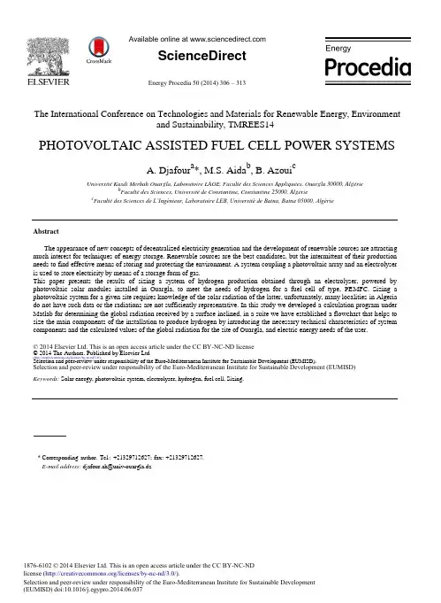
Available online at ScienceDirectEnergy Procedia 50 (2014) 306 – 313The International Conference on Technologies and Materials for Renewable Energy, Environmentand Sustainability, TMREES14PHOTOVOLTAIC ASSISTED FUEL CELL POWER SYSTEMSA. Djafour a*, M.S. Aida b,B. Azoui cUniversité Kasdi Merbah Ouargla, Laboratoire LAGE, Faculté des Sciences Appliquées, Ouargla 30000, Algérieb Faculté des Sciences, Université de Constantine, Constantine 25000, Algériec Faculté des Sciences de L’Ingénieur, Laboratoire LEB, Université de Batna, Batna 05000, AlgérieAbstractThe appearance of new concepts of decentralized electricity generation and the development of renewable sources are attracting much interest for techniques of energy storage. Renewable sources are the best candidates, but the intermittent of their production needs to find effective means of storing and protecting the environment. A system coupling a photovoltaic array and an electrolyser is used to store electricity by means of a storage form of gas.This paper presents the results of sizing a system of hydrogen production obtained through an electrolyser, powered by photovoltaic solar modules installed in Ouargla, to meet the needs of hydrogen for a fuel cell of type, PEMFC. Sizing a photovoltaic system for a given site requires knowledge of the solar radiation of the latter, unfortunately, many localities in Algeria do not have such data or the radiations are not sufficiently representative. In this study we developed a calculation program under Matlab for determining the global radiation received by a surface inclined, in a suite we have established a flowchart that helps to size the main components of the installation to produce hydrogen by introducing the necessary technical characteristics of system components and the calculated values of the global radiation for the site of Ouargla, and electric energy needs of the user.© 2014 Elsevier Ltd. This is an open access article under the CC BY-NC-ND license© 2014 The Authors. Published by Elsevier Ltd.(/licenses/by-nc-nd/3.0/).Selection and peer-review under responsibility of the Euro-Mediterranean Institute for Sustainable Development (EUMISD).Selection and peer-review under responsibility of the Euro-Mediterranean Institute for Sustainable Development (EUMISD)Keywords: Solar energy, photovoltaic system, electrolyser, hydrogen, fuel cell, Sizing.*Corresponding author. Tel.: +21329712627; fax: +21329712627.E-mail address: djafour.ah@univ-ouargla.dz1876-6102 © 2014 Elsevier Ltd. This is an open access article under the CC BY-NC-NDlicense (/licenses/by-nc-nd/3.0/).Selection and peer-review under responsibility of the Euro-Mediterranean Institute for Sustainable Development(EUMISD) doi:10.1016/j.egypro.2014.06.037A. Djafour et al. / Energy Procedia 50 (2014) 306 – 313 3071. IntroductionAlgeria is well endowed with both conventional (non renewable) and non conventional (renewable) sources of energy. The largest non-renewable energy source found in Algeria is fossil (i.e. oil and gas), which is being actively exploited. Renewable sources of energy are also abundant in Algeria, the most important one being the solar. Indeed, the mean yearly sunshine duration varies from a low of 2650 h on the coastal line to 3500 h in the South, the potentialof daily solar energy is important. It varies from a low average of 4.66 kWh/m2 in the north to a mean value of 7.26 kWh/m2in the south. This means that the yearly energy potential on 80% of the territory is of the order of 2650 kWh/m2. The total daily available energy is of the order of 16.56×10¹⁵ Wh [1]. The availability of solar energy is limited only on shiny days. Therefore, it is important to store the solar energy in other form of energy for the usage at night and gloomy weather. Hydrogen has been identified to be an ideal medium for this purpose with an important energy carrier with low harmful emissions, high –efficiency conversions into useful energy forms [2, 3]. The Photovoltaic conversion is one of the most interesting uses of solar energy modes. It provides electricity directly and independently with reliable equipment and duration of relatively high life, allowing reduced maintenance. The combination of this mode of production to the fuel cell through the production of hydrogen to be used by the fuel cellis therefore presented as an ecological mean of energy production. The objective of this work is the study and designof a hybrid photovoltaic system for electrical energy production. Mainly with the production of hydrogen needed to make worked a fuel cell of type, PEMFC, (proton exchange membrane fuel cell). In this work we have developed a mathematical model to design the main elements of the system for producing hydrogen by introducing the technical characteristics necessary as well as climate and solar data of the implantation site of the system.2. System descriptionThe installation is composed of a photovoltaic generator, a proton exchange membrane electrolyser and electronic interfaces between the power sources and the electrolyser, it produces hydrogen and oxygen those are stored and subsequently consumed by the fuel cell. Fig. 1 shows the system with the option of storing electrical energy in batteries for the cloudy days.Photovoltaic Load Management ElectricalGenerator & LoadControl UnitElectricityHydrogenBatteriesWaterElectrolyser H2 Storage Tank Fuel CellO2H2OO2 or Air Fig1.The Hybrid system (PV-PEMFC) for energy production2.1. Photovoltaic FieldPhotovoltaic generator (PV) transforms sunlight directly into electricity. It is composed by several photovoltaic modules, which are composed of solar cells. The maximum load current depends on the size and number of series - parallel modules [4].308 A. Djafour et al. / Energy Procedia 50 (2014) 306 – 3132.2. Fuel Cell (PEMFC)A fuel cell is a generator that directly converts the internal energy of a fuel into electrical energy using anelectrochemical controlled process. Proton exchange membrane fuel cell (PEMFC) is composed of an assembly of cells which include a cathode chamber and an anode chamber separated by two electrodes and an intermediate electrolyte (proton conducting polymer) [5]. Molar gas flow consumed by the fuel cell is represented by [6]:Fgas,pac n cυ Iυ1(1) n υ FK FpacWhere Fgas , pac : Gas flow consumed (mol / s),n c : Cells number,I : Current (A)n : Number of moles of electrons exchanged per mole of water (n = 2 for hydrogen, n = 4 for oxygen) F : Faraday constant, (96485 C/mol),K F pac: Faraday efficiency (%)2.3. Electrolyser (PEME)The principle of operation of a Proton Exchange Membrane Electrolyser (PEME) is based on the same concept as a PEM fuel cell. The water electrolysis using polymer electrolyte membrane presents the advantages of highly pure hydrogen at the output with only water and electricity at the input. This process does not require electrolyte recycling or corrosive electrolyte [2]. Molar flow of gas produced by the electrolyser is represented by [6, 7]:F gas,El =n c× I×ȘF El (2) n × FWhere Fgas,El : gas flow consumed (mol / s), K F El: Faraday efficiency (%)2.4. Storage systemEnergy storage in the autonomous photovoltaic systems is usually provided by batteries, components used in the majority of cases, [8]. The technical characteristics of storage systems can result in significant operational constraints and reduce their field of use. The coupling technologies or hybridizing with complementary properties in certain cases is necessary to circumvent the difficulties associated with the use of a single device. In our case we will consider a system with hybrid storage (storage via hydrogen and storage in the batteries).3.SOLAR RADIATION3.1.Site location and measurementTo determine the solar radiation on the surface of the panels, we have used the coordinates of Ouargla site (latitude 31° 52ƍ N, longitude 5° 24ƍ E with an altitude of 141m). Measurement data of insulation are provided from the National Office of Meteorology of Ouargla for a period of ten years of observation (2000-2009), see Table1,[9]. Table 1. Monthly average of insulation hours for Ouargla [9]Months Jan Feb Mar Apr May Jun Jul Aug Sep Oct Nov Dec Insulation(h) 249.9 246.5 264.3 283.1 279.8 296.9 335 322.6 257.9 256.8 249.2 202.2A. Djafour et al. / Energy Procedia 50 (2014) 306 – 313 3093.2. Model for calculation of solar radiation on a tilted surfaceUsing the Liu and Jordan model, the monthly average daily global radiation on a tilted surface may be computed from the following equation, [9,10, 11].__ ________(3)HcpH 0 K t R__Where H cp : Monthly average daily global radiation on a tilted surface, (Wh/m 2. day) ___H 0 : Monthly average daily extraterrestrial radiation on a horizontal surface. (Wh/m 2. day)_____R : Ratio of the average beam radiation on tilted surface, K t : Monthly-average clearness index(a)(b)Fig.2 Monthly average daily global radiation in function of the tilt angle (ȕ°), (a) January – June, (b) July - December310 A. Djafour et al. / Energy Procedia 50 (2014) 306 – 313Fig.2 shows the results of calculating of the monthly average daily global radiation incident on a south facing surface in Ouargla with the different tilt angles with respect to the horizontal surface (-15 ° to 90 °) with step of 1°.According to Fig. 2 it is clear that the unique optimal angle for each month of the year is the maximum points of each curve. By using El-Kassaby model [12], we have calculated the seasonal optimal angles and by using Gladius model [13], we have calculated the annual optimal angle and by using our chart we have calculated the corresponding global radiation for a south-facing sensor. See Table 2. With an optimum inclination ȕopt (°) annual of 39.14°, the maximum average daily radiation received in Ouargla is equal to 5.889 kWh/m2.day, which gives an average energy of 2149.6 kWh/m2.year,[9].Table 2. Monthly average daily global radiations at monthly, seasonal and annual optimum tilt anglesMonth Dec Jan Feb Mar Apr May Jun Jul Aug Sep Oct Nov ȕopt(°)62 61 52 36 17 0 -7 -4 11 29 47 59 Hcp 5271.6 6157.8 6347.8 6092.6 6454.7 6501.6 6953.1 7162.3 6777 6014.2 5994.5 6209.5 (wh/m².day)Season Winter Spring Summer Autumnȕopt(°)57°15.37°-2.2°43.5°Hcp 5255.4 6146.8 6326.8 5800.8 6451.9 6373.3 6889.8 7132.9 6730.3 5881.8 5986.5 6034.2 (wh/m².day)ȕopt(°)39.14° (Annual optimum tilt angle)Hcp 4939 5803.5 6229.5 6087.9 6152.9 5670.5 5705 6013.3 6247.3 5949.4 5953.2 5920.3 (wh/m².day)4.Sizing of the generator4.1.The descriptive parametersThe most important parameters needed to know for the calculation of the necessary size of the photovoltaic generator in our system are the electrolyser consumption Ec (kWh / day) and the average daily global radiation incident on the collector or the surface of the modules Ei (kWh / m². day). To complete the design of our generator we have based on the following assumptions:-The molar flux produced by the electrolyser is the same as the molar flow consumed by the fuel cell.-The demand is constant during the study period (it can change during the day, but the daily average value remains constant).-Efficiencies of system components are constants.4.2.Evaluation of Electric Power needsIn the present work we choose the use of an electrolyser with a power of 1.920kW to produce the hydrogen needs for the work of a fuel cell with power of 0.5 kW for 6.5 hours each night. According to the assumptions listed in the previous section we have calculated the electrolyser operating duration by using the equations (1) and (2), further to the results of the calculation, to produce the needs of hydrogen, the electrolyser may be obliged to operate for four hours each day with a consumption of 7.68 kWh/day which must be provided by the photovoltaic generator, see Table 3, for the specifications of the electrolyser and of the fuel cell.Table 3. Specifications of the PEM electrolyser and the PEMFC Fuel cell [6].Specifications PEM Electrolyser PEMFC cell bsc 500WRated power 48 V 20VRated power 1920 W 500 WA. Djafour et al. / Energy Procedia 50 (2014) 306 – 313 311Maximal power 2000 W 600 WNumber of cells 26 32Operating Pressure 15 barsOperating current 40 A 25 AOperating temperature 70°C 60°CH2 gas production 0.45 m3/hVoltage by cell 1.84VH2 gas pressure 1atmO2 gas pressure 0.2095 atm4.3. Generator peak powerFrom the electric power needs calculated in previous section and the average daily solar radiation, the corresponding peak power of the generator (Pc) in kWc is calculated by the following equation [14].P cE c(4) KEiWhere:Ec: Energy consumed per day (kWh / day)Ei: The average daily global radiation corresponding to optimal modules slops (kWh / m². day)K: Correction coefficient for systems with battery his value is between 0.55 and 0.75 [14]. The value used in our calculations (system with battery) is equal to 0.68.4.4. Generator sizing resultsThe peaks powers of the generator calculated by the equation (4) for each month with an annual optimum tilt panels, 39.14 °, are shown in Fig. 3. To meet the daily energy needs throughout the year, the minimum of peak power needed to be installed is, Pc = 2.1578 kWc. In this work we choose to use the photovoltaic modules TE 1800 Q from Total Energy, see Table 4, for the specifications of these modules.Table 4. Specifications of the PV module [19]Model type TE1800Q from Total EnergyPeak power, P op 180 WcPeak power voltage, V op 26.8VPeak power current, I op 6.8 AOpen circuit voltage, V oc 33 VShort circuit current, I sc 7.3 AThe sizes 1462mm*973mm*35mmTolerance (%) +/-3Warranty 25 year Fig.3 The peak power required for each month with a 39.14° tilt panels312 A. Djafour et al. / Energy Procedia 50 (2014) 306 – 313In order to ensure the system operation over all the year, the required configuration of the photovoltaic generator is calculated as follow, [6]:The number maximal of modulesN TPc= 2159.7 / 180 = 11.99 modules, ( Pc mod ule : Module peak power (Wc)) Pcmod uleThe number of series modules in each branchN s V L= 48 / 26.8 = 1.79 modules, (V L : Load voltage (V) and V op : Module peak power voltage (V)) V opThe number of branchesN p I L= 40 / 6.8 = 5.88 modules, ( I L : Load current (A) and I op : Module peak power current (A)) I opThen we choose to install twelve modules (six branches in parallel with two series modules in each branch), with the total area of 17.07 m² and a peak power of 2160 Wc.5. Estimating of the storage capacityDetermining the Battery Park (storage capacity) is made taking into account a number of days of autonomy to ensure with zero production. The number of days varies depending on the application and geographical situation [15, 16, 17].CsEc υJ Aut(5) R bυ P dυUWhere:C s: Storage capacity (Ah)Ec : Energy consumed per day (kWh / day)J Aut: Autonomy (day)R b: Battery efficiency (%)P d: Depth of discharge (%)U : Working voltage (V)The capacity in C10 what is necessary to store is evaluated by the next formula [18].C10C S(6)F CSF CS: Is the correction factor (factor used to deduct the capacity in C10 by correcting the calculated capacity), [18].F CS= 1.25 for 1 J Aut 4.5.1. Batteries sizing results and the choice of a regulatorThe number of branches of the batteries can be, Nb (C10/C10batterie), so for our case with an autonomy of one day we found With batteries of 6V and 160 Ah, the number of branches, Nb 2 branches, and for set the voltage of the storage system with the working voltage, we find the number of batteries in series, Ns = 8 batteries. See Table 5, for the specifications of batteries.For the choice of the regulator, the first parameter to consider is the power of regulator, or the maximum current that can be controlled for a given voltage. For the voltage, the regulator will be able to supporter about the double of its rated voltage, value near the open voltage, Voc, of the panel at a low temperature, [8]. For the characteristics of the chosen regulator, see Table 6, for the regulator specifications.A. Djafour et al. / Energy Procedia 50 (2014) 306 – 313 313Table 5. Datasheet of batteries [6] Table 6. Datasheet of the regulator [6]Capacity in C10 160 Ah Maximal current of the generator 45 AEfficiency (Șb)80% Maximal power of the generator 2160 W Overcharge level 6.3 V Maximal operating current 60 AExcessive level of discharge 5.7 V Maximal operating power 2880 W Maximal depth of discharge (PD) 60% Efficiency (Șr) 85%6. ConclusionSolar hydrogen system as an Energy supply is a good solution to solve fuel logistic problem for remote, desert areas in Algeria that can at least be capable of providing necessary light and energy. In this study we have showed an example of sizing of a solar generator that can make a stand-alone hybrid power generation system, mainly with the production of hydrogen needed to run a PEMFC fuel cell, for the purpose of proper management of the electrical energy produced by the PV system, we can say that the results of this design are perfectly theoretical (in the absenceof an experiment). The supposition of some assumptions makes these results approximate.As a perspective, a design based on technical criteria for a realistic case can lead to an acceptable result on the one hand the sizing of the PV array, the storage tank of gas, the storage batteries, and on the other hand, the global efficiency of the system.References[1]R. Boudries, R. Dizene. Potentialities of hydrogen production in Algeria. Int J Hydrogen Energy 2008; 33 (17): 4476 - 4487[2]F. Barbir. PEM electrolysis for production of hydrogen from renewable energy sources. Solar Energy 78, pp.661-669, 2005.[3]R.E. Clarke, S Giddey, F.T. Ciachi, S.P.S. Badwal, B. Paul, J. Andrews. Direct coupling of an electrolyser to a solar PV system for generatinghydrogen. International Journal of Hydrogen Energy 34, pp. 2531-2542, 2009.[4]B. Omar, A. Guen-Bouazza, B. Bouazza, T. Boussoukaia, N. E Chabane-Sa ri. Conception et dimensionnement d’une installation solaireautonome alimentant un poste radio téléphonique mobile de type Emetteur/Récepteur (E/R). 6ème séminaire international sur la physique énergétique, Bechar, 21- 23 Octobre, 2002.[5]P. Stevens, F. Novel-Cattin, A. Hammou, C. Lamy M. Cassir. Pile à combustible. Technique de l’ingénieur, Doc. D3340, 10 Août 2000.[6]H. Abdi, N. Ait Messaoudene, M. Omari, Y. Bekhta. Etude et dimensionnement d’une installation solaire de production d’hydrogène. 2èmeWIH2 Ghardaïa, 2007.[7]Q. Ulleberg. Modeling of advanced alkaline electrolysers a system simulation approach. Int J Hydrogen Energy 28, 2003, pp. 21 - 33.[8]A. Labouret, M. Villoz. Energie solaire photovoltaïque, Manuel du professionnel. Dunod, Paris, 2003.[9]A. Djaf our. Etude d’un système de production d’hydrogène solaire. Thèse de Doctorat, Université d’Ouargla 2013.[10]Beckman W.A, Duffie J.A. Solar engineering of thermal processes. A wiley- interscience, publication, New York. 1980.[11]K. Messaitfa. Evaluation de l’apport quantitatif des inclinaisons optimales d’un système de pompage photovoltaïque. Enersole 01, Adrar,Algérie, 30-31 Octobre 2001, pp255-272.[12]M.M. Kassaby. Monthly and daily optimum tilt angle for south facing solar collectors, theoretical model, experimental and empiricalcorrelations. Solar and Wind Technology, Vol. 5, N°6, pp. 589 –596, 1988.[13]G. Lewis. Optimum sizing on a Collector for a Domestic Water Heating System. Solar and Wind Technology, Vol. 4, N°3, pp. 411 - 414, 1987.[14]L. Chancelier et E. L aurent. L’Electricité Photovoltaïque. Editeur Gret, France, 1996.[15]M. Benbitour, A. Gamma, M. belhamel. Logiciel de dimensionnement des systèmes PV. Bulletin des énergies renouvelables N°10, Décembre2006.[16]J. Royer et al. Le Pompage Photovoltaïque. Manuel de cours, Institut de l’Énergie des Pays ayant en commun l’usage du Français, Québec,Canada, 1998.[17]H. Belmili, M. Ayad, E. M. Berkouk, M. Haddadi. Optimisation de dimensionnement des installations photovoltaïques autonomes - Exemplesd’applications, éclairage et pompage au fil du soleil. Revue des Energies Renouvelables CICME’08 Sousse, 2008, pp. 27 – 39.[18]O. Kebour . Etude et Analyse d’un Habitat Solaire Photovoltaïque. Mémoire de Magister, (Blida) 2004.[19]Web site, http://www.kelvin-solartechnik.de/te.htm. (Site visited in Mai 2006).。
电力行业词汇动力工程潮汐能Ti da l po w e r地热能Geothermal energy地下热能Subterranean heat energy电力需求Power demand电能Electric energy动力需求Power demand二次能源Secondary energy source发电能源构成Compositiono fen ergyfo rel ectricityg eneration发电能源在一次能源消费中的比重Shaero fen ergyfo rel ectircityg enerationin to talpr imary energy废热Waste heat风力能源Wind energy风能Wind energy工业余热Industiralex hausthe at海洋能Marine energy海洋热能Marine thermo energy海洋温差能Marine thermo energy核能Nuclear energy节能Energy savingEn erg y c on se rv atio n节约能源Energy saving聚变能Fusion energy可再生能源Renewable energy source能量平衡Energy balance能量损失Energy loss能源Energy source能源构成Energy source composition能源管理Energy management能源规划Energy source planning能源基地Base of energy source能源开发Energy source development能源强度Energy intensity能源弹性系数Energy elasticity能源消耗Energy consumption能源消费结构Energy consumption structure能源需求Energy demand能源政策Energy policy清洁能源Clean energy resource燃料动力基地Fuelan dp owerba se燃料消耗Fuel consumption燃料消耗率Specific fuel consumption燃料需求Fuel demand生物能Biologicalen ergy生物能源Biological energy水电基地Hydropower base水利能源Hydraulic energy水能Hydropower, Hy dr oen er gy , W a te rp ow er太阳能Solar energy无污染能源Pollution-freee nergy resource新能源New energy resource余热Residualh eat, Af te r-h e at ( rea ct or )原子能Atomic energy再生能源Renewable energy source分布能源Distributed Energy Resource (DER )能源储存、消耗和转换超导储能Superconducting energy storage超导能量储存Superconductive energy storage抽水蓄能Pumped storage线能量转移Linear energy transfer地热能转换Geothermalen ergyc onversion地下储存Underground storage地下气化Underground gasification地下蓄气库Underground compressed air storage reservoir电力系统储能Energy storage for electric power system电容能量储存装置Capacitive energy storage equipment飞轮储能Flywheelen ergys torage由飞轮、变频器、发电电动机和磁悬浮轴承等组成飞轮储能装置。
电能的英语单词1. 定义与释义- 单词:electric energy- 1.1词性:名词- 1.2释义:电荷定向移动所具有的能量,是一种清洁、便捷的能源形式,可用于驱动各种电器设备和提供动力等。
- 1.3英文释义:The energy that is generated by the movement of electric charges and can be used to power various electrical devices and provide kinetic energy.- 1.4相关词汇:electric power(电力),electrical energy(电能,与electric energy常可互换),electric current(电流),voltage (电压)2. 起源与背景- 2.1词源:“electric”一词源于古希腊语“elektron”,意为琥珀。
古希腊人发现用毛皮摩擦琥珀后,琥珀能吸引轻小物体,这是人类对电现象的早期认识。
后来随着科学技术的发展,人们对电的本质和电能的利用有了更深入的了解,从而有了“electric energy”这个词汇来描述电所具有的能量。
- 2.2趣闻:1831年,英国物理学家法拉第发现了电磁感应现象,这一发现为电能的大规模产生和应用奠定了基础。
在早期,电能的应用非常有限,主要用于一些简单的实验和少数特殊场合。
据说,当时有人用电能来电击治疗一些疾病,虽然现在看来这种方法缺乏科学依据,但也反映了人们对电能神奇力量的探索和好奇。
3. 常用搭配与短语- 3.1短语:generate electric energy(产生电能)- 例句:Power plants use various methods to generate electric energy.- 翻译:发电厂使用各种方法来产生电能。
- 3.2短语:store electric energy(储存电能)- 例句:Batteries are devices that can store electric energy.- 翻译:电池是可以储存电能的装置。
不同形式的能源英语能源是现代社会必不可少的资源,它不仅是人们日常生活的基础,同时也是推动经济发展和技术进步的关键因素。
不同形式的能源拥有各自的特点和应用领域,在不同的场合中所涉及的英语也不尽相同。
本文将围绕不同形式的能源英语进行阐述。
第一步:化石能源英语化石能源是指天然产生的矿物质资源,如煤炭、石油和天然气。
这些能源在人类生产生活中占据着非常重要的地位。
当涉及到化石能源的英语时,常常会出现以下几种词汇:1. Coal:煤炭2. Oil:石油3. Natural gas:天然气4. Fossil fuel:化石燃料5. Hydrocarbon:碳氢化合物6. Petroleum refinery:炼油厂7. Oil well:油井8. Coal mine:煤矿第二步:可再生能源英语随着环保意识逐渐加强,可再生能源越来越受到人们的重视。
可再生能源指的是人类一直在使用的能源,如风能、太阳能、水能、地热能等。
在涉及可再生能源的英语表达时,常常会出现以下几种词汇:1. Renewable energy:可再生能源2. Solar energy:太阳能3. Wind energy:风能4. Hydro power:水能5. Geothermal energy:地热能6. Biomass energy:生物质能源7. Solar panel:太阳能电池板8. Wind turbine:风力发电机第三步:核能源英语核能源是指通过核反应释放出来的能量,它的发展受到极大的争议。
当涉及到核能源的英语表达时,常常会出现以下几种词汇:1. Nuclear energy:核能2. Nuclear power plant:核电站3. Nuclear reactor:核反应堆4. Nuclear waste:核废料5. Radiation:辐射6. Uranium:铀7. Plutonium:钚8. Nuclear fusion:核聚变总之,不同形式的能源在英语中所涉及的词汇也各不相同,因此在学习英语的过程中,我们需要根据能源类型来适当地学习相关的词汇和知识,以便更好地理解和表达与能源有关的话题。
新能源常用语中英文对照新能源常用语对照英文传统能源Conventional energy source可再生能源Renewable energy sources高能效技术Energy-efficient technology环境友好型Environmentally friendly可持续性发展Sustainable development生态平衡系统Balanced ecological system生物燃料Biofuel矿物燃料Fossil fuel绿色电力Green power温室气体Greenhouse gases (GHG)温室气体减排GHG emission reduction生态系统Ecosystem全球变暖Global warming京都议定书Kyoto Protocol风力发电场Wind power plant地热发电厂Geothermal power plant光伏发电Photovoltaic power generation水力发电Hydroelectric generation潮汐发电厂Tidal power station核电站Nuclear power plant垃圾电厂Refuse power plant国际固体废物协会International Solid Waste Association (ISWA)0.风力发电Wind Power Generation风力机、风轮机Wind turbine风力发电机Wind-driven generator风力发电机组Wind turbine generator system (WTGS) 风能发电机集群Wind farm风能利用率Utilization rate of wind energy风矢量Wind velocity海上风力发电场Offshore wind farm标准大气压Standard/normal atmospheric pressure 标准风速Standardized wind speed风场布置Wind farm layout风地图Wind atlas电力汇集系统(风力发电机组)Power collection system (for WTGS)电网连接点(风力发电机组)Network connection point ( for WTGS) 电网阻抗相角Network impedance phase angle风力机端口Wind turbine terminal马格努斯效应式风力机Magnus effect type wind turbine风车Windmill风轮实度Rotor solidity风轮尾流Rotor wake风轮偏侧式调速机构Regulating mechanism of turning wind rotor out of the wind sideward尾翼Tail fins顺桨Feathering桨距角Pitch angle节圆Pitch circle, nodal circle节点Pitch point, nodal point变速箱Gearbox旋转采样风矢量Rotationally sampled wind velocity 变速风力发电机Variable speed wind turbine变桨距调节机构Regulating mechanism by adjusting the pitch of blade定桨距失速调节型Constant pitch stall regulated type 变桨距调节型Variable pitch regulated type主动失速调节型Active stall regulated type双馈型风力发电机Double-fed wind turbine generator永磁直驱风力发电机Permanent magnetic direct-driven wind turbine generator恒速恒频Constant speed and frequency变速恒频Variable speed constant frequency 节距角Pitch angle叶尖速比Tip speed ratio叶轮Blade整流罩Spinner, nose cone叶片数Number of blades叶片安装角Blade angle, setting angle of blade 齿数Number of teeth齿市Tooth depth齿面Tooth flank工作齿面Work flank齿槽Tooth space齿根圆Root circle齿顶圆Tip circle柱销套Roller叶根Blade root蜗轮Worm wheel叶片展弦比Aspect ratio叶片根梢比Ratio of tip section chord to root section chord等截面叶片Constant chord blade变截面叶片Variable chord blade叶片扭角Twist of blade增强型玻璃钢翼型叶片Enhanced GRP/FRP airfoil blade叶片几何攻角Angle of attack of blade叶片投影面积Projected area of blade瑞利分布Rayleigh distribution威布尔分布Weibull distribution平均几何弦长Mean geometric chord of airfoil机械寿命Mechanical endurance啮合干涉Meshing interference比恩法Method of bins滑块联接Oldham coupling前缘Leading edge弯度Degree of curvature弯度函数Curvature function of airfoil弯曲刚度Flexural rigidity升力系数Lift coefficient背风Leeward软并网Soft cut-in自动/人工解缆Automatic /manual cable untwisting 停车机构Halt gear风电场Wind farm, wind field, wind power station 风力气象站Wind synoptic station气流Wind stream, airflow气流畸变Flow distortion颤振Flutter外部动力源External power source外推功率曲线Extrapolated power curve自由流风速Free stream wind speed风气候Wind climate风玫瑰图、风向图Wind rose风系、风况Wind regime横向风Cross wind风能潜势Wind energy potential风能密度Wind energy density风功率密度Wind power density风能利用率Utilization rate of wind energy 风资源评估Wind resource assessment启动风速Start-up wind speed切入风速Cut-in wind speed切出风速Cut-out wind speed短时切出风速Short term cut-out wind speed 极端风速Extreme wind speed额定风速Rated wind velocity距离常数Distance constant位移幅值Displacement amplitude对数风切变律Logarithmic wind shear law风廓线风切变律Wind profile wind shear law 对数变幂律Power low for wind shear声的基准风速Acoustic reference wind speed 视在声功率级Apparent sound power level 衰减Attenuation齿啮式联接Dynamic coupling齿宽Face width, tooth width齿廓修形Profile modification齿向修形Axial modification径向销联接Radial pin coupling支撑结构Support structure下风向Downwind direction上风向Upwind direction指向性Directivity (for WTGS)风轮扫掠面积Rotor swept area风剪切Wind shear塔影效应Tower-shadow effect三维旋转效应Three-dimensional (3-D) rotational effect非定常空气动力特征Unsteady aerodynamic characteristic风切变影响Influence by the wind shear风切变指数Wind shear exponent大风安全保护Security protection against gale (strong wind) 迎风机构Orientation mechanism, windward rudder风速表、风速计Anemometer,anemograph风速测定站Anemometry station安全风速Survival wind speed极端风速Extreme wind speed参考风速Reference wind speed水平轴风力机Horizontal axis wind turbine垂直轴风力机Vertical axis wind turbine翼型族The family of airfoil可变几何翼型风力机Variable geometry type wind turbine文丘里管式风力机Venturi tube wind turbine风机控制器Controller for wind turbine全永磁悬浮风力发电机All-permanent magnet suspension wind power generator风场电气设备Site electrical facilities湍流强度、扰动强度、紊流强度Turbulence intensity湍流尺度参数Turbulence scale parameter湍流惯性负区Inertial sub range环境温度Ambient temperature空气动力学Aerodynamics空气制动系统Air braking system室内气候Indoor climate透气性Air permeability防滴Protected against dropping water防溅Protected against splashing防浸水Protected against the effect of immersion 风轮空气动力特性Aerodynamic characteristics of rotor基准粗糙长度Reference roughness length容量可信度Capacity confidence level光电器件Photoelectric device太阳轮Sun gear内齿圈Annulus gear,ring gear内齿轮副Internal gear pair圆柱齿轮Cylindrical gear人字齿轮Double helical gear柔性齿轮Flexible gear刚性齿轮Rigid gear从动齿轮Driven gear主动齿轮Driving gear变位齿轮Gear with addendum modification 小齿轮Pinion大齿轮Gearwheel, main gear行星齿轮Planet gear单级行星齿轮系Single planetary gear train多级行星齿轮系Multiple stage planetary gear train 行星齿轮传动机构Planetary gear drive mechanism 增速齿轮副Speed increasing gear pair非工作齿轮Non working flank齿轮扳手Ratcher spanner柔性滚动试验Flexible rolling bearing空载最大加速度Maximum bare table acceleration 过载度Ratio of overload风力机最大功率Maximum power of wind turbine 最大转速Maximum rotational speed最大系数Maximum torque coefficient风轮最高转速Maximum turning speed of rotor 风轮仰角Angle of rotor shaft空转Idling锁定blocking停机Parking静止Standstill尾迹损失Wake loss轮毂高度Hub height变桨系统Pitch system变桨调节Pitch regulation活动桨Active pitch调向系统Yaw system静音离网型Silent off-network主动偏航Active yawing被动偏航Passive yawing风轮偏航角Yawing angle of rotor shaft气动弦线Aerodynamic chord of airfoil轴向齿距Axial pitch球头挂环Ball eye球头挂钩Ball hook可调钳Adjustable pliers联板Yoke plate接闪器Air termination system发动机舱Engine nacelle微观选址Micro-siting集网风能Central-grid wind energy孤网风能Isolated-grid wind energy 离网风能Off-grid wind energy风柴混合互补系统Wind-diesel hybrid system 潜伏故障Latent fault, dormant failure 严重故障Catastrophic failure使用极限状态Serviceability limit state最大极限状态Ultimate limit state。
1.2.3.4.5.6.7.8.9.10.11.12.13.14.15.16.17.18.19.20.21.22.23.24.25.26.27.28.29.30.31.32.33.34.35.36.37.38.39.40.精心整理87.88.89.90.91.92.93.94.95.96.97.98.99. 100.101.功102. 103. 104. 105. 106. 107. 108. 109. 110. 111. 112. 113. 114. 115. 116. 117. 118. 119. 120. 121. 122. 123. 124. 125. 126. 127.128.精心整理178. 179. 180. 181. 182. 183. 184. 185. 186. 187. 188. 189. 190. 191. 192. 193. 194. 195. 196. 197. 198. 199. 200. 201. 202. 203. 204. 205. 206. 207. 208.209.210.精心整理299.精心整理346.347. 348. 349. 350. 351. 352. 353. 354. 355. 356. 357. 358. 359. 360. 361. 362. 363. 364. 365. 366. 367. 368. 369. 370. 371. 372. 373. 374. 375. 376. 377. 378. 379. 380. 381. 382. 383. 384.385.精心整理468. 469. 470.471.精心整理528. 529. 530. 531. 532. 533. 534. 535. 536. 537. 538. 539. 540. 541. 542. 543. 544. 545. 546.伏-547. 548. 549. 550. 551. 552. 553. 554. 555. 556. 557. 558.559.精心整理651.精心整理737.精心整理793. 794. 795. 796. 797. 798. 799. 800. 801. 802. 803. 804. 805. 806. 807. 808. 809. 810. 811.1.2.3.4.瓦5.安6.7.周8.9.周/10.伏安精心整理18.19.机20.21.22.23.24.25.26.27.28.29.30.31.32.33.34.35.36.37.38.39.40.41.42.43.44.45.1.2.3.4.5.6.7.8.9.10.精心整理50.51.52.1.2.3.4.5.6.7.8.9.10.11.12.13.14.15.16.17.18.19.20.21.22.23.24.25.26.27.28.29.30.31.32.33.34.35.36.37.38.39.精心整理26.27.28.29.1.2.3.4.5.6.7.8.9.10.11.12.13.14.15.16.17.18.19.20.1.2.3.4.5.6.7.8.9.10.11.12.精心整理19.20.21.22.23.24.25.26.27.28.29.30.31.32.33.34.3536.37.38.39.40.41.42.43.44.45.46.47.48.49.50.51.52.53.54.55.56.57.58.精心整理2.3.4.5.6.7.8.9.10.11.12.13.14.15.16.1718.19.20.21.22.23.24.25.ction26.27.28.29.30.31.32.33.34.35.3637.38.精心整理4.5.6.7.8.9.10.11.12.13.14.硅(15.挤接1.2.3.4.5.6.7.8.9.10.11.12.13.14.15.16.17.18.19.20.21.22.1.2.精心整理6.7.8.9.10.11.12.13.14.15.1.2.3.4.5.6.7.8.9.10.11.12.1.插头2.插座3.4.5.6.7.8.9.10.11.12.13.14.15.精心整理8.9.10.11.12.13.14.15.16.17.18.19.20.21.22.23.24.25.26.1.2.3.交流(4.5.6.7.8.9.10.11.12.13.14.15.精心整理59.60.61.62.63.64.65.66.67.68.69.70.71.72.73.74.75.76.77.78.79.80.81.82.83.84.85.86.87.88.89.90.电桥91.92.93.94.95.96.97.98.99. 100. 101.102.精心整理153. 154.155. 156. 157. 158. 159. 160. 161. 162. 163. 164. 165. 166. 167. 168. 169. 170. 171. 172. 173. 174. 175. 176. 177. 178. 179. 180. 181.182.精心整理28.29.30.31.32.33.34.35.36.37.38.39.40.41.42.43.44.1.光源2.照明3.照度4.流明5.6.朗伯7.8.9.10.水银11.钠灯12.氖灯13.彩灯14.15.16.17.18.19.20.21.22.23.24.25.精心整理62.63.矿烛64.65.66.67.68.69.70.71.桅灯72.73.74.75.76.77.78.灯罩79.80.81.82.83.84.85.86.87.88.89.90.91.92.93.94.95.96.灯架97.98.99.精心整理口148. 149. 150. 151. 152. 153. 154. 155. 156. 157. 158. 159. 160.161. 162. 163. 164. 165. 166. 167. 168. 169.1.2.瓷瓶;3.4.瓷管5.瓷嘴(6.7.8.9.精心整理43.44.45.46.47.48.49.50.51.52.53.54.55.56.57.58.59.60.61.62.63.套管1.2.3.电线;4.铜线5.硬线6.7.8.裸线9.母线10.11.12.13.14.15.精心整理55.56.57.58.59.60.61.62.63.64.65.66.67.接线68.69.70.71.72.天线73.74.75.76.77.78.铝线79.80.81.铝排82.83.84.铜排85.86.87.88.89.90.钢丝91.92.93.94.铁丝95.96.97.98.镍丝精心整理151.1.2.3.4.5.6.T7.8.9.10.11.12.13.14.15.16.17.18.U19.U20.21.22.23.24.精心整理68.接地线精心整理。
电力新能源英语Unit 1replenish 再填装满biomass (单位面积或体积内)生物的数量,生物质photovoltaic 光电的megawatt(MW)百万瓦特(电学)geothermal 地热的geysers 间歇泉rated 额定的ethanol 乙醇sugar cane 甘蔗intermittment 间歇的,断断续续的unsightly 难看的couple with 外加,加上legislation 立法incentive 刺激,动机commercialization 商品化,商业化equilibrium 平衡,均衡hydrosphere 水界,水圈latitude 纬度dissipate 消散precipitation 降水,降水量biofuel 生物燃料hydrogen 氢inexhaustible 无穷无尽的,永不枯竭的trough 水槽fossil fuels 矿物燃料alleviation 缓和Unit 2cycle 周期biogas 生物气,沼气trail 跟踪,追踪geothermal power plant 地热发电站extract 榨取tidal power station 潮汐发电站ebb 退潮reversible 可翻转的silicon cell 硅电池irrigation 灌溉atomic reactor原子反应堆mediumOcean thermal energy conversion 海洋热能转换系统conventional 常规的Magneto-hydrodynamic power generator 磁流体发电机conducting fluid 导电流体magnetic field 磁场storage power plant 蓄能电站pure daily-regulated pumped storage power plant 日调节纯抽水蓄能电站water conveyance system 输水系统powerhouse complex 厂房generator motor 发电电动机Unit 3elevation 海拔,高度head 水头earthwork 土方工程draw off 排出spillway 泄洪道flood-discharge gate 泄洪闸silt-discharge gate 冲沙闸catchment 集水crest 顶,鸡冠penstock 水渠shaft 竖井bucket 涡轮叶片impulse turbine 冲击式水轮机reaction turbine 反击式水轮机peak hours 高峰时间off-peak hours 低谷时间drainage 排水runoff 流走之物tidal plants 潮汐发电站ebb 退潮barrage 拦河坝,堰estuary 河口,江口Unit 4organism 生物体incandescent 白热的hydrogen nuclei 氢核helium nuclei 氦核payback 偿还displace 取代untapped 未使用的,未开发的chip 基片,芯片photon 光子photovoltaic(PV)effect 光电效应sparse 稀少的cost-effective 成本效益比collector 聚集器ash disposal 灰渣处理stack emission 咽气(尾气)排放thermal pollution热污染aquaic 水的perturbation 紊乱Unit 5pump water 用泵抽水grind grain 碾碎谷物mill lumber 碾磨木材spinning rotor 旋转转子nacelle 连接舱aerodynamics 空气动力学prolong 延长blade 叶轮backup 支持auxiliary 辅助的offline 脱机的,离线的maintenance 维护longevity 寿命propeller 螺旋桨horizontal-shaft 水平轴address 演说,演讲swishing sound 嗖嗖的声音mask 掩盖shrub 灌木,灌木丛Unit 6bioenergy 生物能bioethanol 生物乙醇biodiesel 生物柴油rapeseed 油菜籽landfill 垃圾Arundo donax 芦竹(Spanish cane)pyrolysis 高温分解deplete 耗尽,使衰竭nitrogen oxide 氯氧化物coconut oil 椰子油caster oil 蓖麻油sugar beet 糖用甜菜maize 玉米carbon monoxide 一氧化碳additive 添加剂MTBE 甲基叔丁基醚gasohol 酒精—汽油混合燃料petroleum spirit 汽油,石精油anaerobic 厌氧的slurry 泥浆dung 粪便toxic chemical 有毒化学物质Unit 7nucleus 原子核deficiency 缺乏,不足fission 裂变fusion 聚变protons 质子neutrons 中子electron 电子strontium 锶iodine 碘xenon 氙trigger 引发,触发self-sustaining 自激的plasma 等离子ionize 电离,使电子化availability 有效性boron 硼control rod 控制棒criticality 临界点graphite moderated reactors 石墨反应堆heavy water moderated reactor 重水反应堆coolant 冷却液fissile 裂变的shield 掩体,护罩lead 铅dilute 稀释disperse 分散uranium 铀Unit 8furnaces 燃烧室step-up transformer 升压变压器substation 变电站load dispatch center 调度中心flue gas 烟气evaporate 蒸发economizer 省煤器water cooling wall 水冷壁super-heater 过热器feed-water 给水conform to 符合,到达drum 汽包down comer 下降管saturated steam 饱和蒸汽lower header 下联箱natural circulation 自然循环pulverize 制粉stator 定子rotor 转子shaft gland 轴封blade wheel 叶轮assembly 装配,组装frame 框架magnet core 磁芯,铁芯winding 绕组rated 额定的transient 暂时的be subjected to 遭受nozzle 喷口steam inlet 进汽口diaphragm 叶片spray 喷射multi-stage turbines 多级汽轮机electromagnetic induction 电磁感应reverse 相反,倒转electric charge 电荷electrical circuit 电路reciprocating 来回的,交替的handcrank 动摇把,手动曲柄compressed air 压缩空气DC(direct current)直流电EMF(electromotive force)电动势armautre 电枢。
就电气新能源英语作文Now the electric vehicle more refers to a pure electric vehicle, which uses a single energy storage battery as the power source to provide power for the car. It uses the battery as the energy storage power source, and provides power to the motor through the battery to drive the motor to run and drive the car forward. From the appearance, the electric vehicle and the electric vehicle complement each other, and the daily vehicle does not see any The main difference lies in the power source and drive system, that is, the engine of pure electric vehicle is the traditional automobile engine, and the battery is equivalent to the original tank electric vehicle, including six parts: chassis, body, battery, motor, controller and battery auxiliary facilities.Because the motor has good traction characteristics, it does not need the transmission clutch and transmission of the battery vehicle The speed is controlled by the controller. The speed control system of the motor can realize the impact on the environment because of its relatively small speed control. The prospect is generally optimistic, but the current technology is not mature.。
1.一次能源:一次能源是指取自自然界没有经过加工转换的各种能源。
二次能源:经过一次能源加工后得到的能源产品称为二次能源终端能源:供给社会生产、非生产和生活中直接用于消费的各种能源2.分布式能源:建立在用户端的能源供应模式,即可独立运行,也可并网运行,而不论规模大小,使用什么燃料或应用的技术分布式能源主要特征:高效性、环保性、能源利用多样性、调峰作用、可靠性、减少国家配电投资、解决边远地区供电。
3.风的四部分:1.基本风。
2.随机风。
3.造变风。
4.脉动风4.并网型风力发电机组控制有定桨失速调节、变桨距调节、主动失速调节。
5.风力机分为:水平风力机,垂直风力机6.风力发电系统控制的目标有4个:1.保证系统运行可靠性。
2.能量利用率最大。
3.电能质量高。
4.机组寿命长。
7.变速恒频风力发电系统的控制策略:低于额定风速时,跟踪最大风能利用系数,以获得最大能量。
高于额定风速时,跟踪最大功率,并保持输出功率稳定。
8.风力发电机组并网条件:1.波形相同。
2.幅值相同。
3.频率相同4.相序相同。
5.相位相同9.风力发电经济性指标:风力发电的经济性指标主要有:单位千瓦造价、单位千瓦时投资成本、财务内部收益率和财务净现值、投资回收期及投资源利润率。
10风力异步发电机并网方式:1.直接并网。
2.降压并网。
3.晶闸管软并网。
11.无刷双馈异步发电机的变速恒频风力发电系统工作原理:取消了电刷和集电环,系统运行可靠性增大,系统体积变大。
功率控制器根据功率给定与反馈值频率检测信号按一定的控制规则输出频率和电流控制信号,无刷双馈发电机的转子的转速随风速的变化而变化,以保证系统运行在最佳工况下,提高风能转化效率。
当发电机转速变化时,由变频器来改变控制绕组频率,以使发电机的输出频率与电网一致。
12.太阳能转换与应用包括:太阳能采集、转换、储存、传输与应用等方面太阳能转换方式:太阳能—热能、太阳能—电能、太阳能—氢能、太阳能—生物质能、太阳能—机械能13.光伏发电原理:根据光伏效应,利用太阳能电池将太阳能直接转化为电能。
New and emerging developments in solar energyD.Y.Goswami *,S.Vijayaraghavan,S.Lu,G.TammSolar Energy and Energy Conversion Laboratory,Department of Mechanical and Aerospace Engineering,University of Florida,P.O.Box 116300,Gainesville,FL 32611-6300,USAAbstractSolar energy can potentially play a very important role in providing most ofthe heating,cooling and electricity needs ofthe world.With the emergence ofsolar photocatalytic detoxification technology,solar energy also has the potential to solve our environmental problems.However,we do not see widespread commercial use ofsolar energy.Some ofthe emerging developments in solar may change that situation.This paper describes some ofthe new and emerging de-velopments,with special emphasis on:(1)nanoscale antennas for direct conversion of sunlight to electricity with po-tential conversion efficiencies approaching 80–90%;(2)new thermodynamic cycles for solar thermal power,that have the potential to reduce capital costs by 50%;and (3)solar photocatalytic oxidation for cleanup of industrial wastewater,drinking water,soil and air.The paper describes the f undamentals ofeach ofthese developments,their potential,present status and future opportunities for research.(1)Nanoscale antenna solar energy conversion:The current photovoltaic technologies rely on the quantum nature of light and semiconductors which are fundamentally limited by the band-gap energies.A revolutionary new approach suggested by Professor Robert Bailey in 1972revolves around the wave nature of light.Professor Bailey suggested that broadband rectifying antennas could be used for solar to d.c.conversion.These rectennas would not have the fun-damental limitation ofsemiconductor band-gap limiting their conversion efficiencies.Rectennas f or solar conversion would have dimensions ofthe order ofthe wavelengths ofsolar radiation which f alls mostly in the sub-micron range.The challenges in actually achieving the objectives are many.This paper describes the challenges and approaches to their solution.(2)New thermodynamic cycles for solar thermal power:It is recognized that the capital costs of solar thermal power will have to be reduced by about 50%in the near future in order to make it competitive with fossil fuels (especially natural gas)based power systems.Potential exists for meeting this goal by reducing the costs and improving the thermodynamic performance of power cycles by hybridization and combined cycle approaches and by employing new and innovative ideas in thermal power cycles.This paper describes the new thermodynamic approaches with an em-phasis on an innovative new thermodynamic cycle using ammonia and water mixtures as the working fluids.(3)Solar photocatalytic detoxification and disinfection of water and air:Although the potential of solar radiation for disinfection and environmental mitigation has been known for years,only recently has this technology been sci-entifically recognized and researched.Solar photocatalytic oxidation has been demonstrated to effectively treat groundwater,drinking water,and industrial wastewater.In some applications such as decoloration and reduction of COD it may be the only effective method oftreatment.Treatment ofindoor air by the photocatalytic method has been demonstrated as the most effective technology for that application.This paper describes the recent developments and identify challenges and future research opportunities.Ó2003Elsevier Ltd.All rights reserved.1.Antenna solar energy conversionDirect solar energy conversion to electricity is con-ventionally done using photovoltaic cells,which makes use ofthe photovoltaic effect.The photovoltaic effect*Corresponding author.Fax:+1-352-392-1071.E-mail address:goswami@ufl.edu (D.Y.Goswami).0038-092X/$-see front matter Ó2003Elsevier Ltd.All rights reserved.doi:10.1016/S0038-092X(03)00103-8Solar Energy 76(2004)33–43/locate/solenerdepends on interaction ofphotons,with energy equal to, or more than the band-gap ofthe photovoltaic materi-als.Over many years ofresearch,the efficiency of photovoltaic cells has incrementally increased.Although silicon is the most commonly used material till date, other materials such as GaAs have also been used. Compound(multiple junction)cells have been devel-oped with two or more layers ofcells.Some ofthe losses due to the band-gap limitations are avoided by cascad-ing semiconductors ofdifferent band-gaps.The antenna concept,on the other hand,relies on the fact that solar radiation is electromagnetic in nature.In other words,the waves are oscillating electric and mag-neticfields propagating from the sun to the earth.The use ofantennas f or signal(and power)transmission and re-ception is a very well-developed science in the microwave frequencies.Brown(1984),of the Raytheon Company,a pioneer ofmicrowave power transmission,coined the term‘‘rectenna’’,for rectifying antenna.Reception and conversion ofmicrowave radiation(at2.45G Hz)at close to90%efficiencies have been recorded in the literature.The advantage ofthe antenna approach to solar en-ergy conversion is that,primarily,conversion would not be band-gap limited as in photovoltaic cells.It is as-sumed while making this assertion that the process of rectifying these high frequency electromagnetic waves will not involve any such lossy quantum effects.The idea ofconverting solar energy into usef ul d.c. electricity using antennas wasfirst patented by J.C. Fletcher ofNASA,and R.L.Bailey ofthe University of Florida,based on a summer project at the NASA Goddard Center in the late1960s.The patent describes the idea as a device for converting electromagnetic wave energy into electric power consisting ofa number of relatively close spaced electromagnetic wave absorber elements having tapered portions responsive to a wide band electromagnetic wave radiation.A fewfigures of the proposed device from the patent(Fletcher and Bai-ley,1973)are shown in Fig.1.Pyramidal antennas were tested at microwave fre-quencies(100–1000MHz)to verify their broadband characteristics and to provide some preliminary concept validity evidences(Bailey,1972).It is in this paper that Bailey proposed the use ofhis electromagnetic wave energy converter as a solar energy converter.Subse-quently,Bailey et al.(1975)did some initial theoretical work and literature search,to identify important pa-rameters and to determine the future direction of re-search.The study focused on the absorption(or reception)ofEM radiation by the antennas,while in-dicating that rectification ofthe signals was an equally critical issue and a tough challenge.Some analogies to insect antennas and to the rods and cone structures present in the eye were drawn.These antennas were also used as a basis to predict the geometry and materials of solar antenna construction.Subsequently,Farber(1988)worked on the antenna based energy conversion concept at the University of Florida’s Solar Energy and Energy Conversion Labo-ratory.As a part ofhis work,he transmitted microwave radiation in the0.2–3GHz range using broadband metallic pyramidal antenna elements across the labora-tory,where it was picked up by pyramidal dielectric antennas and rectified to d.c.This d.c.power was used to run a small motor as a proofofconcept.Farber’s work covered three frequency ranges,0.2–3,10and100 G Hz.Bulk ofhis work was done at10G Hz,where he characterized hollow dielectric pyramidal antennas to determine parameters such as optimum base size,length over base ratio,array spacing etc.Some spot checks of those results were performed at100GHz.Farber also used a suitably modified carborundum paper in which the paper backing was scraped thin and metallic current collector wires randomly applied,to test undervisible Fig.1.A descriptivefigure showing the tapered broadband EWEC elements connected to a rectification arrangement (Fletcher and Bailey,1973).34 D.Y.Goswami et al./Solar Energy76(2004)33–43light.The grade ofthe paper was such that the SiC particles were approximately ofthe right size as deter-mined from his earlier experimentation.Some output was observed on his instruments by testing,but it is not clear as to whether that was because ofthe antenna ef-fect.Lin et al.(1996)reported seeing a short circuit cur-rent using a fabricated sub-nanostructure consisting of a parallel dipole array connected to a rectification ar-rangement.This is possibly thefirst and only experi-mental observation ofresonance light absorption and rectification in the visible light range.The idea ofcon-verting optical radiation to electrical energy was also suggested by Gustafson and Billman(1974).Much of their research in the past had been focused on optical diodes.Brown(1984)reviews the development ofmicrowave rectennas(rectifying antennas).Most of the initial test-ing was done at2.45GHz.Dipole antenna arrays cou-pled to semiconductor rectifier bridges were placed in the front of a microwave beam to absorb the energy and convert to d.c.Over time,very good microwave to d.c. efficiencies were obtained.For instance,at a demon-stration at the JPL Goldstone Facility,the power was transmitted over a distance ofmore than1mile.Over 30kW ofd.c.power was obtained f rom the rectenna with a ratio ofd.c.output to incident microwave power of0.84.All these results go to prove that high efficiency microwave to d.c.conversion is possible.Dipole antennas are linearly polarized antennas.Suh et al.(2000)obtained a maximum conversion efficiency of60%using a circularly polarized truncated-corner square patch microstrip antenna at5.8GHz.Yoo and Chang(1992)also tested rectennas at10and35GHz with conversion efficiencies of60%and39%,respec-tively.The limitation in these tests was found to be with the diodes used for rectification.A primary question is whether antennas can be used to receive high frequency,small wavelength signals. There are several references in the literature to antenna coupled radiation detectors(see Codreanu et al.,1999; Chong and Ahmed,1998;Osterman et al.,1997).These detectors use several kinds ofantennas,such as bow-tie, log-periodic,and spiral antenna,etc.The antennas are coupled to a resistance which dissipates the power picked up by the antenna into heat.Therefore,it does appear feasible that conversion of solar radiation from electromagnetic radiation to useful electric power is possible.In the past,one ofthe biggest factors preventing any significant development in this area has been the ability to work at the length scales of the wavelengths ofthe visible radiation.With the advent ofnanotechnology and the improvements in semicon-ductor processing technologies,we might be at a point where experiments can be done to test this concept.It is hypothesized that EM wave to d.c.conversion can be done at solar frequencies with potentially much higher conversion efficiencies than with present day photovoltaic technologies.The challenges in actually achieving this objective are many.They are summarized below:•Scale:Antennas for solar conversion have to have di-mensions ofthe order ofwavelengths ofsolar radia-tion that falls in the sub-micron range.This size range brings up the associated challenges off abrica-tion,interconnection,quality control,mass-manufac-turing and such.•Material:What type ofmaterials are best suited f or working at solar frequencies?The antennas will prob-ably have to be made ofdielectric materials,the choice being decided by the effect on antenna losses.•Rectification:The received waves will have to be rec-tified to d.c.to be useable.Such high frequency recti-fication would be quite a challenge,which will have to be overcome.•Antenna properties:The antenna array will have to be optimized in order to achieve good conversion effi-ciencies.The antenna geometry and materials will have to be selected such that the array is broadband, ofgood beam-width,circularly polarized,and with a center frequency in the solar range.•Impedance matching:Good impedance matching while working with broadband signals will be an-other challenge to be overcome.The length scales for the antennas have to be of the order ofthe wavelength ofthe radiation as seen in Table 1.The antenna length for solar radiation would be in the range ofless than a micron to a f ew microns while the width at its broadest point(assuming a conical struc-ture)would be in the sub-micron down to nanometerTable1Length and time scales ofelectromagnetic radiationFrequency(Hz)Wavelength(in vacuum)(m)Time period(s)Regime/source 1093·10À11·10À9Microwave 10113·10À31·10À11Millimeter wave 10123·10À41·10À12Far infrared 10143·10À61·10À14Infrared10153·10À71·10À15UltravioletD.Y.Goswami et al./Solar Energy76(2004)33–4335range.The structures would evidently have high aspect ratios.The diode structures would be sized again depending on the wavelengths involved.Typically,most devices have to be made such that their physical dimensions are small compared to the wavelength ofthe signals prop-agating through them.For lumped rectifying structures,the dimensions could easily slip into the nanoregime.The work in mo-lecular electronics and nanoelectronics could prove to be useful,in achieving antenna solar energy conversion (ASEC)goals.In fact,molecular diodes are already a reality.Work in the field ofnanotechnology has resulted in molecular diodes,molecular wires,carbon nanotubes and many such technologies that open up exciting op-portunities in the area molecular or nanoelectronics.The diodes developed so far have demonstrated very poor high frequency characteristics.Fig.2shows an array ofcarbon nanotubes that could form the antenna array for ASEC concept.Alterna-tively,biological antenna array could be formed from algae cells (Yamazaki et al.,1988).Fig.3shows a schematic representation ofmulti-layered structures ofa biological antenna ofalgae (Fig.3a)and an antenna made up ofLangmuir–Blodgett (L–B)films (Fig.3b).Yamazaki et al.(1988)have shown experimentally that energy transfers at wavelengths of 620and 560nm are possible.They also showed that biological antennas are more efficient in energy transfer than the artificial L–B films.1.1.MaterialAt higher frequencies,the losses are higher in metallic antennas.Metals have very high conductivities,which,based on solutions to Maxwell’s equations and electro-magnetic property models,would imply a very lossy propagation through the medium.For this reason,at higher frequencies,the tendency is to use dielectric an-tennas.Dielectric antennas are generally oftwo types,dielectric loaded antennas and ‘‘true’’dielectric anten-nas.Dielectric loaded antennas consist ofa dielectric structure between the metallic part (wires)and free space.True dielectric antennas are lens-like structures without any metals involved in guiding the wave in.1.2.RectificationThe biggest stumbling block in achieving the ASEC concept is the ability to rectify electromagnetic waves at the high frequency range of visible and IR radiation.Conventional rectification devices are available forfre-Fig.2.Array ofcarbon nanotubes that could f orm the antenna array for ASEC concept.(Courtesy :Dr.A.Rao,Clemson,University).Fig.3.(a)Schematic representation ofmulti-layered structures ofa biological antenna ofalgae;and (b)an antenna made up ofL–B films (from Yamazaki et al.,1988,p.5036).36 D.Y.Goswami et al./Solar Energy 76(2004)33–43quencies that are several orders ofmagnitude lower.As stated earlier,recent developments in nanotechnologies and molecular electronics could prove to be very useful.In addition,a search ofthe literature reveals two areas ofwork that may be ofinterest.In the1970s, Professor Javan’s group at MIT and Professor Gustaf-son and colleagues at UC Berkeley worked on metal–oxide–metal(MOM)devices.These devices consist ofa thin barrier layer,an oxide,sandwiched between two metal electrodes.The device works when a large enough field causes the tunneling ofelectrons across the barrier layer.Initially these devices consisted ofafine tungsten wire(‘‘cat whisker’’)pressed against a metal plate.Some dirt or other insulating material caught between the whisker and the plate provided the barrier.Such diodes were difficult to fabricate reproducibly.Heiblum et al. (1978)reviewed the state ofthe art until then and de-scribed some MOM diodes fabricated using microfab-rication techniques.The performance of these diodes appears promising,and has been shown up to the far infrared frequencies.The other rectification idea is that ofIshii(1969) where Ishii proposed a‘‘distributed parameter power rectifier’’(DPPR).In a more recent paper,Ishii(1991), proposed a design for a DPPR for use in a‘‘Tokamak’’nuclear fusion reactor for the conversion of1–30THz radiation into d.c.power––this is just a few orders of magnitude below optical frequencies.In general,diodes have to have certain characteristics that would enable their efficient operation at such high frequencies.The diodes should have a size that makes them lumped devices.They should have incredibly small switching times.The space charge layer(ifthat is the type energy band used for rectification)should not ab-sorb the incoming radiation.Just as in transmitting or receiving antennas,it will be necessary to implement impedance matching ar-rangements between the antenna and the rectifier,or between the antenna and the transmission line.The broadband nature further increases the complications in implementing impedance matching.Impedance match-ing is important to ensure maximum power transfer between components and thus to minimize reflection losses.In conclusion,the concept ofantenna solar energy conversion is an extremely challenging and interesting idea.Ifthe conversion can be achieved,and ifit turns out that the conversion process is actually as effective as it appears to be,based on the current optimistic pre-dictions,that would mean a revolution in solar energy utilization.It needs to be stressed that most ofthe an-alyses as oftoday have been rather simplistic.They have not answered the key question ofwhether antenna the-ory would actually hold at the extremely high frequen-cies involved,even theoretically.Solar frequency rectification is a problem,the domain ofwhich lies at frequencies several orders of magnitude above current capabilities.In a way,what is sought is a way to imitate the mechanisms in nature,such as the eye,except that the goal,like in photosynthesis is to collect energy,ef-ficiently.That statement alone should bring into focus the enormous magnitude ofthe challenge.It would re-quire an interdisciplinary team ofresearchers and some very well-focused,innovative research.Needless to say, such an endeavor would be quite expensive.2.Novel combined power/refrigeration thermodynamic cycleDuring the last two decades a number ofresearchers have worked on developing new thermodynamic cycles or improving existing ones.One approach to improve thermal power cycles is to use multi-component working fluids(Goswami,1998).A single component working fluid,such as steam,boils isothermally at constant pressure.However,a multi-component workingfluid boils at variable temperatures with a change in the liquid composition ofthe components.This variable temper-ature boiling process yields a better thermal match with sensible heat sources than a constant temperature boil-ing process and therefore improves the resource effec-tiveness.An important type ofmulti-componentfluid is ammonia/water mixture.Kalina(1983)proposed theuse Fig.4.Schematic ofcombined power/ref rigeration cycle(Xu et al.,2000).D.Y.Goswami et al./Solar Energy76(2004)33–4337ofammonia/water mixtures as working fluids in the bottoming cycle ofa combined cycle power plant.Other investigators who have analyzed Kalina cycle using ammonia–water mixtures include Marston (1990),Park and Sonntag (1990),Ibrahim and Klein (1996)and Rogdakis and Antonopoulos (1991).Goswami and Xu (1999)have given a detailed review ofthe literature.Goswami (1995,1998)proposed a new thermody-namic cycle,which is an ammonia-based combined power/refrigeration cycle.In addition to combining the advantages ofmixed working fluids,the novel cycle uses very high concentration ammonia vapor in the turbine,which allows the vapor to be expanded to a much lower temperature without condensation,thus providing re-frigeration.The ammonia vapor is then condensed by absorption.This cycle will be able to use low quality heat sources,including geothermal energy and solar energy,while achieving high thermal efficiency.The proposed cycle is shown schematically in Fig.4.The relatively strong basic solution ofammonia–water leaves the absorber as saturated liquid at the cycle lowpressure.It is pumped to the system high pressure and is preheated before entering the boiler by recovering heat from the weak solution returning to the absorber.As the boiler operates between the bubble and dew point tem-peratures ofthe mixture at the system high pressure,partial boiling produces a high concentration saturated ammonia vapor and relatively low concentration saturated liquid.The liquid weak solution gives up heat in the re-covery unit and is throttled into the absorber.The rec-tifier condenses out water to further purify the vapor,by rejecting heat to a secondary strong solution line before entering the boiler.The vapor is superheated and ex-panded through the turbine to produce work.Due to the low boiling point ofammonia the vapor expands to low temperatures yielding the potential for refrigeration.The vapor is finally absorbed back into the liquid giving offheat,which is rejected to the ambient environment.Xu et al.(2000)conducted an analysis ofthe cycle and concluded that the cycle can utilize low temperature heat sources,such as solar and geothermal energy,and produce both power and refrigeration at efficiencies approaching the Carnot efficiency.Goswami and Xu (1999)conducted a parametric study to analyze the effect of cycle parameters on the performance and found that the cycle maybe optimized for thermal performance.Fig.5shows an example that points out that optimum conditions may be found to maximize the efficiency.In fact,the cycle may be optimized for second law efficiency or other performance parameters,such as power output,refrigeration output,etc.Lu and Goswami (2002)optimized the cycle using a generalized reduced gradient (GRG)algorithm.They analyzed the performance of this cycle under optimized conditions for a heat source temperature of 360K which is achievable by using high efficiency flat plate collectors,and 440K which is achievable by using inexpensive parabolic trough e ofsuch collectors has the potential to reduce the cost ofa solar thermal power plant by 30–50%.Lu and Goswami (2002)optimizedtheFig.5.Efficiencies ofthe optimized cycle at various heat source temperatures,optimized for second law efficiency (Tamm et al.,in press).Table 2Optimum working conditions for maximum second law efficiency (360K heat source temperature,290K ambient temperature)Point T (K)P (bar)h (kJ/kg)s (kJ/kg K)X Flow-rate (kg/s)1295.0 5.5)105.10.198920.6733 1.00002295.113.0)104.10.19890.6733 1.00003325.213.045.70.68050.6733 1.00004333.113.01371.9 4.49560.99350.20665311.113.0102.90.59230.89490.01106311.113.01302.7 4.27930.99900.19567311.113.01302.7 4.27930.99900.19568280.6 5.51195.5 4.27930.99900.19569285.0 5.51278.3 4.57300.99900.195610333.113.045.20.73050.59420.804411300.113.0)106.80.25000.59420.804412300.25.5)106.80.25320.59420.804438 D.Y.Goswami et al./Solar Energy 76(2004)33–43cycle forfirst law and second law efficiencies defined by Eqs.(1)and(2),respectively,using a COP of1:g1¼W netþQ cool=COPm hsðhhsÀhhsÞð1Þg 2¼W netþQ cool=COPm hs½ðh inhsÀh0ÞÀT0ðs inhsÀs0Þð2ÞTables2and3show the optimum working condi-tions and cycle performance parameters optimized for maximum second law efficiency for a source temperature of360K and a sink temperature of290K.It is seen that for a workingfluidflow-rate of1kg/s,the ideal cycle produces about20kW ofpower and16.2kW ofre-frigeration at a second law efficiency of54.22%.Fig.5 shows efficiencies ofthe optimized cycle at various heat source temperatures,optimized for second law effi-ciency,using the energy removed from the heat source in the denominator and a Carnot COP in Eq.(2).3.Photocatalytic detoxification and disinfection of water and airAlthough the potential ofsolar radiation f or disin-fection and environmental mitigation has been known for years,only recently has this technology been scientifically recognized and researched.This research is especially important in view ofthe enormous environmental prob-lems created by industrial development.In the United States alone,more than30000hazardous-waste sites have been identified as causing groundwater contami-nation,and more than100million tons ofaqueous pro-cess waste is estimated to be generated by industry each year.Also,it is well known that underground petroleum storage tanks have contaminated soil and groundwater by leakage at sites all over the world.Conventional treatment methods such as activated charcoal absorption and air stripping simply transfer the pollutants from one medium to another.Solar photocatalytic technology,on the other hand,breaks up the toxic chemicals and com-pletely mineralizes them.In many cases,such as removal ofcolor or reduction ofchemical oxygen demand(COD) in industrial wastewater,solar technology may provide the only effective treatment that does not cause any ad-ditional problems.Potential applications ofthe solar detoxification process include groundwater remediation,industrial wastewater treatment,soil decontamination,disinfec-tion ofhospital waste,disinf ection ofdrinking water, and detoxification ofindoor air.Because ofthe enor-mous potential ofthe process,extensive research is being conducted all over the world(Blake,1995).A number of review articles have been published covering the funda-mental aspects ofthe photochemistry,reactor designs, and engineering systems.Blake et al.(1992),Hoffmann et al.(1995),Kamat(1993),Legrini et al.(1993),Lins-ebigler et al.(1995),Ollis et al.(1989),Ventaktadri and Peters(1993)and Goswami(1995,1997)have described in detail engineering aspects ofthe photocatalytic pro-cess,practical solar reactor designs and an engineering system design methodology for wastewater treatment, and will not be repeated here.Despite the great potential for detoxification of wa-ter,there has been very little commercial or industrial use ofthis technology.Published literature shows only three engineering scale demonstrations for groundwater treatment in the USA and one industrial wastewater treatment in Spain.Engineering scalefield experiments were conducted by National Renewable Energy Labo-ratory at Lawrence Livermore National Laboratory to treat groundwater contaminated with trichloroethylene (TCE)(Mehos and Turchi,1993).Thefield system consisted of1700f t2(158m2)ofparabolic trough reac-tors,using Degussa P25TiO2particles as the catalyst in a slurryflow configuration.With0.1%TiO2concentra-tion in the slurry,the TCE concentration was reduced from220to less than5ppb.Engineering scale demonstration ofthe nonconcen-trating solar reactor technology was conducted at Tyn-dall Air Force Base in1992(Goswami et al.,1993). Groundwater contaminated with fuel,oil and lubricants leaking from underground storage tanks was treated. Contaminants ofinterest included benzene,toluene, ethylbenzene and xylenes(BTEX)although there were other chemicals also present in the groundwater.The field tests were successful in demonstrating the feasibility ofdestroying BTEX in the groundwater(G oswami et al., 1993),as seen in Fig.6.In a recent commercial application,Goswami(1998) used nonconcentrating reactors to treat groundwaterTable3Cycle performance for optimum conditions in Table2Boiler heat input272.9kJ/sSuperheat input0kJ/sAbsorber heat rejection269.1kJ/sTurbine work output21.0kWVapor quality at turbine exit93.93%Pump work input 1.0kWRefrigeration capacity16.2kWTotal heat input272.9kJ/sNet work output19.99kWFirst law efficiency13.26%Heat sourceflow-rate 2.183kg/sHeat source entrance temperature360KHeat source exit temperature330.2KWork output per1kg/s massflow-rateofheat sourcefluid9.16kWRefrigeration output per1kg/s massflow-rate ofheat sourcefluid7.42kWSecond law efficiency54.22%D.Y.Goswami et al./Solar Energy76(2004)33–4339。
电力行业词汇动力工程潮汐能Ti da l po w e r地热能Geothermal energy地下热能Subterranean heat energy电力需求Power demand电能Electric energy动力需求Power demand二次能源Secondary energy source发电能源构成Compositiono fen ergyfo rel ectricityg eneration发电能源在一次能源消费中的比重Shaero fen ergyfo rel ectircityg enerationin to talpr imary energy废热Waste heat风力能源Wind energy风能Wind energy工业余热Industiralex hausthe at海洋能Marine energy海洋热能Marine thermo energy海洋温差能Marine thermo energy核能Nuclear energy节能Energy savingEn erg y c on se rv atio n节约能源Energy saving聚变能Fusion energy可再生能源Renewable energy source能量平衡Energy balance能量损失Energy loss能源Energy source能源构成Energy source composition能源管理Energy management能源规划Energy source planning能源基地Base of energy source能源开发Energy source development能源强度Energy intensity能源弹性系数Energy elasticity能源消耗Energy consumption能源消费结构Energy consumption structure能源需求Energy demand能源政策Energy policy清洁能源Clean energy resource燃料动力基地Fuelan dp owerba se燃料消耗Fuel consumption燃料消耗率Specific fuel consumption燃料需求Fuel demand生物能Biologicalen ergy生物能源Biological energy水电基地Hydropower base水利能源Hydraulic energy水能Hydropower, Hy dr oen er gy , W a te rp ow er太阳能Solar energy无污染能源Pollution-freee nergy resource新能源New energy resource余热Residualh eat, Af te r-h e at ( rea ct or )原子能Atomic energy再生能源Renewable energy source分布能源Distributed Energy Resource (DER )能源储存、消耗和转换超导储能Superconducting energy storage超导能量储存Superconductive energy storage抽水蓄能Pumped storage线能量转移Linear energy transfer地热能转换Geothermalen ergyc onversion地下储存Underground storage地下气化Underground gasification地下蓄气库Underground compressed air storage reservoir电力系统储能Energy storage for electric power system电容能量储存装置Capacitive energy storage equipment飞轮储能Flywheelen ergys torage由飞轮、变频器、发电电动机和磁悬浮轴承等组成飞轮储能装置。
电力新能源英语
Unit 1
replenish 再填装满
biomass (单位面积或体积内)生物的数量,生物质photovoltaic 光电的
megawatt(MW)百万瓦特(电学)
geothermal 地热的
geysers 间歇泉
rated 额定的
ethanol 乙醇
sugar cane 甘蔗
intermittment 间歇的,断断续续的
unsightly 难看的
couple with 外加,加上
legislation 立法
incentive 刺激,动机
commercialization 商品化,商业化
equilibrium 平衡,均衡
hydrosphere 水界,水圈
latitude 纬度
dissipate 消散
precipitation 降水,降水量
biofuel 生物燃料
hydrogen 氢
inexhaustible 无穷无尽的,永不枯竭的
trough 水槽
fossil fuels 矿物燃料
alleviation 缓和
Unit 2
cycle 周期
biogas 生物气,沼气
trail 跟踪,追踪
geothermal power plant 地热发电站
extract 榨取
tidal power station 潮汐发电站
ebb 退潮
reversible 可翻转的
silicon cell 硅电池
irrigation 灌溉
atomic reactor原子反应堆
medium
Ocean thermal energy conversion 海洋热能转换系统
conventional 常规的
Magneto-hydrodynamic power generator 磁流体发电机
conducting fluid 导电流体
magnetic field 磁场
storage power plant 蓄能电站
pure daily-regulated pumped storage power plant 日调节纯抽水蓄能电站water conveyance system 输水系统
powerhouse complex 厂房
generator motor 发电电动机
Unit 3
elevation 海拔,高度
head 水头
earthwork 土方工程
draw off 排出
spillway 泄洪道
flood-discharge gate 泄洪闸
silt-discharge gate 冲沙闸
catchment 集水
crest 顶,鸡冠
penstock 水渠
shaft 竖井
bucket 涡轮叶片
impulse turbine 冲击式水轮机
reaction turbine 反击式水轮机
peak hours 高峰时间
off-peak hours 低谷时间
drainage 排水
runoff 流走之物
tidal plants 潮汐发电站
ebb 退潮
barrage 拦河坝,堰
estuary 河口,江口
Unit 4
organism 生物体
incandescent 白热的
hydrogen nuclei 氢核
helium nuclei 氦核
payback 偿还
displace 取代
untapped 未使用的,未开发的
chip 基片,芯片
photon 光子
photovoltaic(PV)effect 光电效应sparse 稀少的
cost-effective 成本效益比
collector 聚集器
ash disposal 灰渣处理
stack emission 咽气(尾气)排放thermal pollution热污染
aquaic 水的
perturbation 紊乱
Unit 5
pump water 用泵抽水
grind grain 碾碎谷物
mill lumber 碾磨木材
spinning rotor 旋转转子
nacelle 连接舱
aerodynamics 空气动力学
prolong 延长
blade 叶轮
backup 支持
auxiliary 辅助的
offline 脱机的,离线的maintenance 维护
longevity 寿命
propeller 螺旋桨
horizontal-shaft 水平轴
address 演说,演讲
swishing sound 嗖嗖的声音
mask 掩盖
shrub 灌木,灌木丛
Unit 6
bioenergy 生物能
bioethanol 生物乙醇
biodiesel 生物柴油
rapeseed 油菜籽
landfill 垃圾
Arundo donax 芦竹(Spanish cane)pyrolysis 高温分解
deplete 耗尽,使衰竭
nitrogen oxide 氯氧化物
coconut oil 椰子油
caster oil 蓖麻油
sugar beet 糖用甜菜
maize 玉米
carbon monoxide 一氧化碳
additive 添加剂
MTBE 甲基叔丁基醚
gasohol 酒精—汽油混合燃料
petroleum spirit 汽油,石精油
anaerobic 厌氧的
slurry 泥浆
dung 粪便
toxic chemical 有毒化学物质
Unit 7
nucleus 原子核
fission 裂变
fusion 聚变
protons 质子
neutrons 中子
electron 电子
strontium 锶
iodine 碘
xenon 氙
trigger 引发,触发
self-sustaining 自激的
plasma 等离子
ionize 电离,使电子化
availability 有效性
boron 硼
control rod 控制棒
criticality 临界点
graphite moderated reactors 石墨反应堆heavy water moderated reactor 重水反应堆coolant 冷却液
fissile 裂变的
shield 掩体,护罩
lead 铅
dilute 稀释
disperse 分散
uranium 铀。