digi2005操作手册
- 格式:pdf
- 大小:9.73 MB
- 文档页数:45
USER MANUALDIGI BROADCAST (Rev. 3.1.0 Eng)CONTENT1INTRODUCTION (3)2DIGI-SETUP (3)2.1S OURCES (3)2.2D EVICES (6)2.3C OMMUNICATION M ANAGER (8)3ON-AIR (10)4PLAYLIST (13)5FUNCTIONS (15)5.1F ILLER (15)5.2H OT K EYS (16)5.3M ACRO (17)5.4E MERGENCY (18)5.5D EVICES (19)5.6S CHEDULE (21)6FINAL CONSIDERATION AND AXEL TECHNOLOGY CONTACT (23)1 INTRODUCTIONDigi-Broadcast is a dedicated software suite for the automatic multichannel broadcasting of multimedia files elaborated from Digiware.It’s composed by:DIGI-SETUP - System configurationDIGI-BROADCAST - Schedule broadcastingDIGI-VIEWER – Logs viewerDigi-Broadcast controls Vcr, robots, and external devices automatically. It’s a high level software and needs to be set up from expert on television systems, broadcasting devices with an advanced knowledge of signal routing. Digi-Broadcast w orks with a routing IP managed by “Communication server” that is an Axel Technology software. For the recording, it uses DML.Before installing it, you have to set all the net units, where installation files and videos will be placed. Normally, we use to set that unit as “W”.Now you’re ready to run the Digi-tv setup and follow the install shield:At the end of the installations, it will appear on the desktop the icon that will aim you to configure all the television system: video switchers, video cards, VCR, recording devices, macro and datas.2 DIGI-SETUPThe default installation is set for a basic composition composed by a server, a video switcher (identified as Switcher1) and DeckLink video card from Black Magic.Opening the Setup dialog window it will aim you to configure all the devices you will use to broadcast your TV channel, grouped in Sources, Devices, Digibroadcast, Digimedia, Macro input and output.2.1 SOURCESWith “Sources” we identify input videos, such as files, satellite signals, feed from editing suites, control rooms etcDigi-Tv set by default three sources:HDR: with the information about the path’s directory “W:\VIDEO\” and “W:\GRAFICA\”LINEIMPORT: with the path where the video clips you will use into the schedule are storedTo add more sources:Selecting “Insert” it will open a new window where it will be possible to define the name of the new input.For example, a satellite feed will be inserted in the category “Line” and in “Command default” you will be able to set the link and the communication to the video switcher.For any source you can define: Name – (typed from the user) Type – 5 categories: HDR (File) Line VTR Import Import DMLPath – to set the net path for video and graphicClicking on the row “Scheduler#” it will open the new engine “Digi -Brodcast”At “Level 0” it will aim you to set the source path: GPI, video switchers, or a MacroWhile at “Level 1” you will be able tochoose from several different optionsWith “Level 0”we mean all the events that can’t be timed but that coincide with the start of a video clip, and for this reason can’t be associated to “Broadcast event” such as Video Switchers, devices, commands. With “Level 1” we mean all that operations that can be ti med also after the start of the video clip such as the overlapping of a logo.For example: choosing “Pos i tioning Logo” it will open this specific dialog window:2.2 DEVICESWith “Devices” we identify all the physical equipments linked to the broadcasting system.Digisetup will show two main category of equipments.- Switcher 1- DeckLink Video Card- DS-LOCAL- DM-OnairThe first one is dedicated to the Video Switcher and the signal routing, where it will be necessary to set:Name of the PC/ IP address IP PortTime OutThe second one, shown as “Direct Show”, includes all the multimedia drivers used on Windows.“Insert”.2.3 COMMUNICATION MANAGERThe management of all the linked equipments is operated by “Communication Server” a specific software that manages the IP communications between all the devices that compose the broadcasting system.All the settings defined from the “Communication Server”will be used from Digi-Broadcast to control the deviceon all the On-air operations.INTRODUCTIONDigi-Broadcast is an automatic broadcast software that plays video files elaborated from Digiware and controls automatically, video switchers, VCR, robots and external devices.The following screenshot represents the main Digi-Broadcast window and could be divided into three main parts:On-AirPlaylistFunctions3 ON -AIRThis is the section that contains all the elements information, options and commands connected to the played clip and the daily schedule.1 Date and Time of the systemSystem Status2 Total length of the On-air clip Position of the On-air clipRemaining time of the On-air clipAdvance / Delay of the played clip calculated from the Exported Digiware’s scheduleAdvance/Delay in comparison with the next locked clip3Schedule’s date and time exported from DigiwareEffective date and time of playoutCategory (the information is loaded from the clip’s form edited in Digiware) Name of the clip.4Macro (command) linked to the played clip.5Manual stopBroadcasted clip statusClip parameters 63 4124 5876Audio Level and On-air monitor of the on-air clip.7On-air clip A/V parameters (values can be also modified inside the clip form into Digimedia section)7.1Modify the audio level of the on-air clip.7.2Define and change the order of the fields.7.3Resolution resizing of the on-air clip7.4Zoom FunctionFormat 4:3 / 16:9In this section it will show the main functions from the buttons “Play”, “Stop” etc.. The “On” status is shown as the same button in green version.8Places the schedule at the current time, prepares clips and starts broadcasting theschedule with time delay 0 (automatically trim the clip to be transmitted).Places the schedule at the current time.Plays the scheduled clip.Gets in pause the on-air clip.Stops the on-air clip.Stops the on-air clip, plays the next one scheduled and re-starts the previous clip from the break point (it will be added next).Stops the on-air clip and re-starts it from the beginning.Stops the on-air clip and jumps to the next one.Force the insertion of a “Filler Clip” into the schedule (when not inserted automatically from the automation).Automatic insertion of a “Filler Clip” when the player is in advance respect to the scheduled time.NB: It will consider for inclusion the next clip with locked hour, this control is carried out in the next 20 clips from the one onair at this momentForce the pre-loading of the next clip to allow the operator to jump on it and go on-air quickly.Shows the “mode” the system is playing the scheduleNB: when “manual” mode is ON, the counter “Remaining Time” will be displayed in red toalert that at the end of the played clip the system will be stopped.4 PLAYLISTUnder the “Play”, “Stop” and “Position” buttons are displayed the following six events on the schedule. Each event has specific buttons and information:1Clip number on the schedule, reference thumbinal and lenght of the clip.2Skip the selected clip.Manual Start of the event.Manual Stop of the event.3 Playout count down of that clip.Schedule Date and Time of the clip exported from Digiware.Date and time of the effective playout of the clip.Clip category (the information is loaded from the clip’s form edited in Digiware)4Name of the clip.The clip has been checked and preloaded, ready to be played. NB: The preload function forces the preloading if not preloaded automatically.The clip was checked and is waiting to be preloaded.Clip properties.The clip has a locked “On -air time” (min and max range time). NB: This function could be defined also from the operator in this section and not only from Digiware.1234Type of device that will be used for playing.Video format.Show the list of the “Filler clips”.Selecting one clip from the schedule and pressing “Filler”, the selected clip will be replaced with the selected filler.Show the list of the “Emergency clips”. Selecting one clip from theschedule and pressing “Emergency”, the selected clip will be replaced with the selected emergency clip.5 FUNCTIONSIn the lowest part of the screen are placed the buttons that allow you to get into other Digi Broadcast sections.Show all the processes done from the system.5.1 FILLERPressing “Filler” button, will be displayed the following section:It will show the complete list of filler clips (defined by Digiware) available to be automatically added, if “AUTOFILL” is on, or manually by the button “Insert Filler”.For each clip it will display the following information:Name of the clip.Lengtht of the clip.Marked point where the clip can be stopped.Device used for the playout.123 45 6“Interruptible clip”. If the led is green, means that the clip could be interrupted, otherwise, if the led is red, the clip will be added to the schedule only if it can be played for the complete length.5.2 HOT KEYSPressing “Hot Key” button, will be disp layed the following section:Through the “Hot Key” function, it will be possible to combine videoclips to the key from F1 to F12 of your keyboard. In this way you’ll be able to use the system in a live mode or as a Jingle Machine. It is possible to set and save several keyboards.Dropdown menu where you can select the clip to link to a key.Key button linked to the clip.Dropdown menu where you can select the clip tolink to a key.(for each button is possible to set more than a clip).5.3 MACROPressing “Macro” button, will be displayed the following section:A Macro is a command that could be connected to a key, or a clip. It is a useful way to automate operations you can select from a dropdown menu.These automatic commands could generate: switching function on an external video switcher, GPI, start and stop of logos and crawls etc..For each “Macro” it will display the following information:Name of the clip.Associated command.Displayed in two status. If the macro is on (green led) ordisabled (red led).5.4 EMERGENCYPressing “Emergency” button, will be displayed the following section:For each clip will be displayed the following information:Name of the clip.Length of the clip.Marked point where the clip can be stopped.Device used for the playout.Displays if the clip is interruptible (green led) or not (red led).5.5 DEVICESPressing “Devices” button, will be displayed the following section: For each device will be displayed the following information:1 Reference thumbinal.In this sample is represented a Blackmagic DeckLink video card (HDR). Video Switcher thumbinal.GPI Device (General Purpose Interface).Clicking two times on the icon “Video Switcher” it is possible to see the status of the video cross connections.Clicking two times on the icon “GPI” it is possible to see the status of the inputs and outputs.When the device is not active, it will be displayed with a red cross on it. Device Status. Display the command associated to the device.Display the command associated to the relativesource.5.6 SCHEDULEPressing “Schedule” button, it will display the schedule previously exported from Digiware.For each row of the schedule will be shown the following information:Displays if the clip has a locked playout time.Displays if the clip is recorded and stored in the videoserver(green led) or not (red led).Displays if the clip was recorded and marked (green led) or not(red led).Date and time of the clip setted and exported from Digiware.Effective date and time of playoutLenght of the clipName of the clipAdvance / Delay of the clip calculated from the exportedDigiware schedule and the current status of broadcasting.Displays possible instances that could compromise the correctplayout of the clip. If everything is running in the right way, thefield will be displayed empty of information.Display the current status of the scheduled clips.Device used for the playout.Video file’s name of the clipIn the lowest portion of the screen there are more buttonsThis buttons allow you to filter theclips into the database thanks to themetadata added into Digiware.Choosing one of them you’ll be able to choose quickly the file you want to play.The trim button will open the section named Digi-Edit.The control board of Digi-Edit allows you to trim and modify only the selected clip.It is not a global change, but the modification will be applied for that specific line of schedule.Allows to surf the list with “Up” and “Down”Reload the schedule refreshing all theparameters.Displays all the invalid clips (missing, unmarked) and that can’t be broadcasted.The list of the invalid clips will be displayed in the following window.6 FINAL CONSIDERATION AND AXEL TECHNOLOGY CONTACT________________________________________________________________________________________________ ________________________________________________________________________________________________ ________________________________________________________________________________________________ ________________________________________________________________________________________________ ________________________________________________________________________________________________ ________________________________________________________________________________________________ ________________________________________________________________________________________________ ________________________________________________________________________________________________ ________________________________________________________________________________________________ ________________________________________________________________________________________________ ________________________________________________________________________________________________ ________________________________________________________________________________________________ ________________________________________________________________________________________________ ________________________________________________________________________________________________ ________________________________________________________________________________________________ ________________________________________________________________________________________________ ________________________________________________________________________________________________ ________________________________________________________________________________________________ ________________________________________________________________________________________________ ________________________________________________________________________________________________ ________________________________________________________________________________________________ ________________________________________________________________________________________________ ________________________________________________________________________________________________ ________________________________________________________________________________________________ ________________________________________________________________________________________________ ________________________________________________________________________________________________ ________________________________________________________________________________________________ ________________________________________________________________________________________________ ________________________________________________________________________________________________ ________________________________________________________________________________________________ ________________________________________________________________________________________________ ________________________________________________________________________________________________ ________________________________________________________________________________________________ ________________________________________________________________________________________________ ________________________________________________________________________________________________ ________________________________________________________________________________________________ ________________________________________________________________________________________________ ________________________________________________________________________________________________ Main Office BOLOGNA: Via Caduti Di Sabbiuno 6/F40011 Anzola Emilia - Bologna - ItalyTel. +39 051 736555 - Fax. +39 051 736170For Technical information or support**************************For General information and Sales dept************************。
DIGIZON簡易說明手冊目錄一、硬體安裝說明…………………………………………………P.02二、遙控器對應說明………………………………………………P.08三、軟體安裝說明…………………………………………………P.10四、軟體使用說明…………………………………………………P.13五、錄影功能說明…………………………………………………P.26六、預約錄影功能說明……………………………………………P.27七、取用錄影檔案說明……………………………………………P.30八、使用視訊會議說明……………………………………………P.32九、珍典影帶轉檔說明……………………………………………P.34十、MP4檔案播放說明…………………………………………P.35一、硬體安裝說明1、首先確認是否配件全部齊全2、將有線電視的纜線裝上DIGIZON所附的訊號轉接頭(配件6)後,再將該接頭接上DIGIZON的天線輸入端,並再將線路有輸出端將訊號接到電視上3、使用網路線將DIGIZON接上網路。
(建議先確認家中網路是否可正常上網)4、將DIGIZON接上電源,並按下黃色電源開關將電源開啟5、按下開關後,先確定電源燈是否有正常點亮,如按下後無反應,可將按壓的速度放慢即可,而網路如果正常接通,網路燈也會正常亮起。
6、硬體安裝完成後,如下圖:二、遙控器對應說明1、DIGIZON PLAYER和DVN遙控器對應按鍵2、DVN遙控器說明三、軟體安裝說明1、首先將附贈光碟放入電腦光碟機內,電腦即會出現以下之安裝畫面。
如無自行出現此畫面,請進入到我的電腦中,並在光碟機上按滑鼠右鍵、並點下自動撥放即可。
2、按下軟體安裝之按鍵以開始播放軟體安裝,畫面中English為安裝英文版本的撥放器,此時請選擇Chinese(Taiwan)以安裝中文版本的撥放器,選好後即可按下ok之按鍵以繼續安裝。
3、於此步驟請直接按下一步即可。
3、最後按下Finish即可完成軟體安裝。
CL2005通讯屏管理系统使用说明(V1.3)12006年3月2目录第一章概述 (5)第二章安装与运行 (5)第一节安装 (5)第二节运行 (6)第三章系统设置 (8)第一节通讯设置 (8)第二节显示屏规格、自动开关屏时间设置 (8)第四章节目制作 (9)第一节选择要播放的图片 (9)第二节设定图片的播放顺序 (10)第三节设计图片的播放效果 (11)第四节编辑原始文件 (12)第五章通讯 (12)第一节发送数据 (12)第二节控制显示屏电源 (13)第三节汉字点阵库 (13)第六章时钟版面设计 (14)第一节显示时钟 (15)第二节显示“安全天数” (16)第七章多屏信息管理、多用户管理及日志 (17)第一节多屏信息管理 (17)3第二节多用户管理 (18)第三节日志 (19)4第一章概述CL2005通讯屏管理系统是一套全新的节目制作管理系统。
用户使用它制作节目时简单直接。
节目的数据来源可以是图片、文本文件或Word文档,更可以直接输入颜色字体可变化的文本信息。
CL2005系统可播放安全天数,可实现精确到分的定时播放,还可以实现每天的定时开关显示屏。
对已经上载到显示屏的图片或文字信息,CL2005还提供点播功能,即只播放其中的部分节目内容。
CL2005系统支持RS232通讯模式和RS422、RS485通讯模式。
通过外接的扩展设备,CL2005系统还支持调制解调器、以太网等有线远程通讯模式和GPRS无线远程通讯模式。
运行CL2005系统需要Microsoft Office 2000或Microsoft Office XP 的支持。
推荐在Windows XP以及Office XP环境下运行。
第二章安装与运行第一节安装在计算机上运行CL2005Setup.exe程序,屏幕上出现如下的画面:5点击[开始]即可将CL2005通讯屏管理系统安装到计算机上。
第二节运行在[开始]菜单中,选择[程序]->[CL2005通讯屏管理系统]->[CL2005]即可启动CL2005通讯屏管理系统。
2005+ NR 用户手册目录目录 (2)第一章前言 (4)1.1感谢 (4)1.2用途 (4)1.3约定 (4)1.4版权声明 (4)第二章认识宽带路由器 (5)2.1面板布置 (5)2.1.1后面板 (5)2.1.2前面板 (6)2.1.3侧面板 (7)第三章连接到宽带路由器 (8)3.1建立LAN口连接 (8)3.2建立WAN口连接 (8)3.3连接电源 (8)3.3应用示例 (9)第四章配置宽带路由器 (10)4.1基本配置指南 (10)4.1.1 配置您的计算机 (10)4.1.2 ISP 配置 (11)4.1.2.2 WAN配置 (11)4.1.3 局域网配置 (14)4.2高级配置指南 (15)4.2.1路由表配置 (15)4.2.2 NAT 和DMZ 配置 (16)4.2.2.1 DMZ 主机设置 (16)4.2.2.2 虚拟服务配置 (16)4.2.3 防火墙 (17)4.2.3.1 MAC 过滤配置 (17)4.2.3.2 互联网访问控制 (18)4.2.3.3 安全防御 (19)4.2.5动态域名设置 (19)4.2.5.1 DYNDNS DDNS (19)4.2.5.2 每步 DDNS (20)4.2.5.3 花生壳 DDNS (20)4.2.5综合设置 (21)4.2.5.1管理密码修改 (21)4.2.5.1远程管理端口 (21)4.2.5.2 UPnP 设置 (21)4.2.5.3 WAN口链路状态设置 (22)4.2.5.4 恢复缺省参数 / 重启系统 (22)4.2.5.5 固件升级 (23)4.2.6 统计信息 (23)4.2.7 系统日志 (24)附录 (25)附录A常见问题回答 (25)附录B配件清单 (27)附录C W INDOWS 95/98/2000/XP环境下TCP/IP设置 (28)Windows XP 系统的配置 (28)Windows 2000 系统的配置 (30)Windows 98/95/Me 系统的配置 (33)Windows NT4.0 系统的配置 (35)建立正确的网络设置 (38)附录D特性与规格说明 (39)主要特性 (39)规格 (40)附录E技术支持 (40)第一章前言1.1感谢非常感谢您选用Netcore 2005+ NR SOHO宽带路由器产品!Netcore 2005+ NR 宽带路由器是集路由器、防火墙于一身,专为满足需要共享上网及网络资源分享的家庭、家庭办公、小型办公室而设计产品。
00000034证号:沪制号执行标准:GB/T7722-2005TM-A系列条码打印计价秤SY-Ab/Ac/Ad/Ae系列电子收银秤TM-H系列价格标签秤电脑软件使用手册上海大华电子秤厂(2014)目录一、软件安装 (1)二、通讯设置 (4)2.1 通讯模式 (4)2.2 以太网设置 (4)2.3 串行设置 (4)2.4 秤网卡设置 (4)三、操作指南 (6)3.1 商品设置 (6)3.1.1 刷新 (6)3.1.2 查询 (6)3.1.3 过滤 (7)3.1.4 删除 (7)3.1.5 下载 (8)3.1.6 回收 (8)3.1.7 导入 (9)3.1.8 导出 (10)3.2 标签设置 (10)3.2.1 新建 (10)3.3 热键设置 (11)3.4 特殊信息设置 (11)3.5 文本设置 (12)3.6 时钟设置 (13)3.7 系统参数设置 (13)3.8 电子秤初使化 (14)四、进销存 (15)4.1 采购 (15)4.1.1 进货 (15)4.1.2 查询 (16)4.1.3 退(调)货 (16)4.1.4 撤单 (16)4.1.5 导出 (17)4.2 销售 (17)4.2.1 回收 (17)4.2.2 导出 (17)4.2.3 查询 (18)4.2.4删除 (19)4.3 盘点 (19)4.3.1盘点 (20)4.3.2导出 (20)4.3.3查询 (21)4.3.4撤单 (21)4.4 库存 (21)五、报表 (22)5.1 采购报表 (22)5.2 销售日报表 (22)5.3 销售月报表 (22)5.4 销售秤报表 (23)5.5 销售秤报表 (23)5.6 损耗报表 (23)5.7 利润分析 (23)六、系统 (24)2一、软件安装上位机软件安装步骤如下:首先电子秤所附带光盘放入电脑光驱中,打开文件夹,将带有大华安装包标志的图标双击,出现如下界面,如图1.1:图1.1单击:“Next”进入下一步,出现如下界面,如图1.2所示:图1.2单击:“Next”进入下一步,单击“Change“浏览安装路径,如安装到d盘,出现如下界面,如图1.3所示:图1.3注:一般将软件安装到未安装系统的硬盘,一盘系统盘安装在C盘。
00000034证号:沪制号执行标准:GB/T7722-2005TM-A系列条码打印计价秤SY-Ab/Ac/Ad/Ae系列电子收银秤TM-H系列价格标签秤电脑软件使用手册上海大华电子秤厂(2014)目录一、软件安装 (1)二、通讯设置 (4)2.1 通讯模式 (4)2.2 以太网设置 (4)2.3 串行设置 (4)2.4 秤网卡设置 (4)三、操作指南 (6)3.1 商品设置 (6)3.1.1 刷新 (6)3.1.2 查询 (6)3.1.3 过滤 (7)3.1.4 删除 (7)3.1.5 下载 (8)3.1.6 回收 (8)3.1.7 导入 (9)3.1.8 导出 (10)3.2 标签设置 (10)3.2.1 新建 (10)3.3 热键设置 (11)3.4 特殊信息设置 (11)3.5 文本设置 (12)3.6 时钟设置 (13)3.7 系统参数设置 (13)3.8 电子秤初使化 (14)四、进销存 (15)4.1 采购 (15)4.1.1 进货 (15)4.1.2 查询 (16)4.1.3 退(调)货 (16)4.1.4 撤单 (16)4.1.5 导出 (17)4.2 销售 (17)4.2.1 回收 (17)4.2.2 导出 (17)4.2.3 查询 (18)4.2.4删除 (19)4.3 盘点 (19)4.3.1盘点 (20)4.3.2导出 (20)4.3.3查询 (21)4.3.4撤单 (21)4.4 库存 (21)五、报表 (22)5.1 采购报表 (22)5.2 销售日报表 (22)5.3 销售月报表 (22)5.4 销售秤报表 (23)5.5 销售秤报表 (23)5.6 损耗报表 (23)5.7 利润分析 (23)六、系统 (24)2一、软件安装上位机软件安装步骤如下:首先电子秤所附带光盘放入电脑光驱中,打开文件夹,将带有大华安装包标志的图标双击,出现如下界面,如图1.1:图1.1单击:“Next”进入下一步,出现如下界面,如图1.2所示:图1.2单击:“Next”进入下一步,单击“Change“浏览安装路径,如安装到d盘,出现如下界面,如图1.3所示:图1.3注:一般将软件安装到未安装系统的硬盘,一盘系统盘安装在C盘。
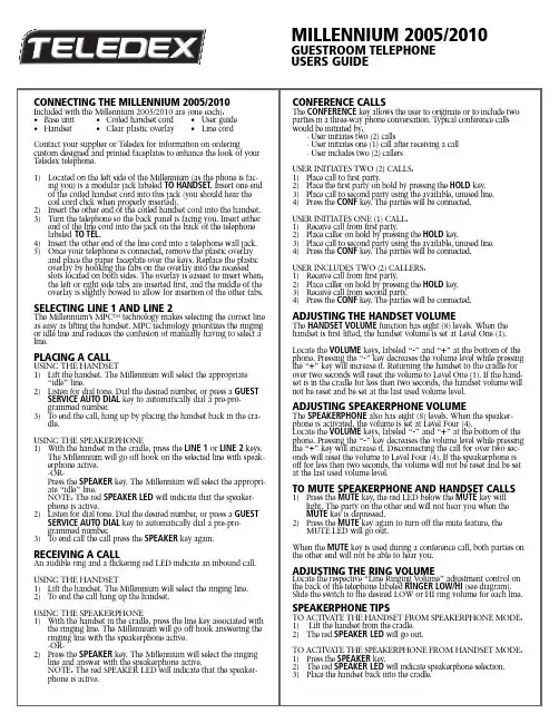
CONNECTING THE MILLENNIUM 2005/2010 Included with the Millennium 2005/2010 are (one each):•Base unit•Coiled handset cord•User guide •Handset•Clear plastic overlay•Line cord Contact your supplier or Teledex for information on ordering custom designed and printed faceplates to enhance the look of your Teledex telephone.1)Located on the left side of the Millennium (as the phone is fac-ing you) is a modular jack labeled TO HANDSET.Insert one end of the coiled handset cord into this jack (you should hear thecoil cord click when properly inserted).2)Insert the other end of the coiled handset cord into the handset.3)Turn the telephone so the back panel is facing you. Insert eitherend of the line cord into the jack on the back of the telephonelabeled TO TEL.4)Insert the other end of the line cord into a telephone wall jack.5)Once your telephone is connected, remove the plastic overlayand place the paper faceplate over the keys. Replace the plastic overlay by hooking the tabs on the overlay into the recessedslots located on both sides. The overlay is easiest to insert when;the left or right side tabs are inserted first, and the middle of the overlay is slightly bowed to allow for insertion of the other tabs. SELECTING LINE 1 AND LINE 2The Millennium’s MPC TM technology makes selecting the correct line as easy as lifting the handset. MPC technology prioritizes the ringing or idle line and reduces the confusion of manually having to select a line.PLACING A CALLUSING THE HANDSET1)Lift the handset. The Millennium will select the appropriate“idle” line.2)Listen for dial tone. Dial the desired number, or press a GUESTSERVICE AUTO DIAL key to automatically dial a pre-pro-grammed number.3)T o end the call, hang up by placing the handset back in the cra-dle.USING THE SPEAKERPHONE1)With the handset in the cradle, press the LINE 1or LINE 2keys.The Millennium will go off hook on the selected line with speak-erphone active.-OR-Press the SPEAKER key. The Millennium will select the appropri-ate “idle” line.NOTE: The red SPEAKER LED will indicate that the speaker-phone is active.2)Listen for dial tone. Dial the desired number, or press a GUESTSERVICE AUTO DIAL key to automatically dial a pre-pro-grammed number.3)T o end call the call press the SPEAKER key again. RECEIVING A CALLAn audible ring and a flickering red LED indicate an inbound call. USING THE HANDSET1)Lift the handset. The Millennium will select the ringing line.2)T o end the call hang up the handset.USING THE SPEAKERPHONE1)With the handset in the cradle, press the line key associated withthe ringing line. The Millennium will go off hook answering the ringing line with the speakerphone active.-OR-2)Press the SPEAKER key. The Millennium will select the ringingline and answer with the speakerphone active.NOTE: The red SPEAKER LED will indicate that the speaker-phone is active.CONFERENCE CALLSThe CONFERENCE key allows the user to originate or to include two parties in a three-way phone conversation. T ypical conference calls would be initiated by;- User initiates two (2) calls- User initiates one (1) call after receiving a call- User includes two (2) callersUSER INITIATES TWO (2) CALLS:1)Place call to first party.2)Place the first party on hold by pressing the HOLD key.3)Place call to second party using the available, unused line.4)Press the CONF key. The parties will be connected.USER INITIATES ONE (1) CALL:1)Receive call from first party.2)Place caller on hold by pressing the HOLD key.3)Place call to second party using the available, unused line.4)Press the CONF key. The parties will be connected.USER INCLUDES TWO (2) CALLERS:1)Receive call from first party.2)Place caller on hold by pressing the HOLD key.3)Receive call from second party.4)Press the CONF key. The parties will be connected. ADJUSTING THE HANDSET VOLUMEThe HANDSET VOLUME function has eight (8) levels. When the handset is first lifted, the handset volume is set at Level One (1). Locate the VOLUME keys, labeled “-” and “+” at the bottom of the phone. Pressing the “-” key decreases the volume level while pressing the “+” key will increase it. Returning the handset to the cradle for over two seconds will reset the volume to Level One (1). If the hand-set is in the cradle for less then two seconds, the handset volume will not be reset and be set at the last used volume level. ADJUSTING SPEAKERPHONE VOLUMEThe SPEAKERPHONE also has eight (8) levels. When the speaker-phone is activated, the volume is set at Level Four (4).Locate the VOLUME keys, labeled “-” and “+” at the bottom of the phone. Pressing the “-” key decreases the volume level while pressing the “+” key will increase it. Disconnecting the call for over two sec-onds will reset the volume to Level Four (4). If the speakerphone is off for less then two seconds, the volume will not be reset and be set at the last used volume level.TO MUTE SPEAKERPHONE AND HANDSET CALLS 1)Press the MUTE key, the red LED below the MUTE key willlight. The party on the other end will not hear you when theMUTE key is depressed.2)Press the MUTE key again to turn off the mute feature, theMUTE LED will go out.When the MUTE key is used during a conference call, both parties on the other end will not be able to hear you.ADJUSTING THE RING VOLUMELocate the respective “Line Ringing Volume” adjustment control on the back of the telephone labeled RINGER LOW/HI(see diagram). Slide the switch to the desired LOW or HI ring volume for each line. SPEAKERPHONE TIPSTO ACTIV ATE THE HANDSET FROM SPEAKERPHONE MODE:1)Lift the handset from the cradle.2)The red SPEAKER LED will go out.TO ACTIV ATE THE SPEAKERPHONE FROM HANDSET MODE:1)Press the SPEAKER key.2)The red SPEAKER LED will indicate speakerphone selection.3)Place the handset back into the cradle. MILLENNIUM 2005/2010 GUESTROOM TELEPHONEUSERS GUIDEUSING THE HOLD KEYThe HOLD key places the call on hold locally at the Millennium tele-phone.TO PLACE A CALL ON HOLD1)With a call active press the red HOLD key.2)The red line LED will change to a slow blink indicating the callis on hold.TO REMOVE A CALL FROM HOLD1)Press the line key of the call on hold. This will remove the callfrom hold making the call activate on either speakerphone orhandset.2)The red line LED will return to steady in-use condition.TO CHANGE PHONES AFTER PLACING A CALL ON HOLD1)Place the call on hold at the Millennium.2)Pickup the call at another telephone. The Millennium will detectthe pickup and remove the hold condition at the originalMillennium.REDIALTO REDIAL THE LAST TELEPHONE NUMBER DIALED:1)Lift the handset from the cradle, or press the SPEAKERPHONE key.2)Press the REDIAL key.GUEST SERVICE AUTO DIAL KEYSThe Millennium has five programmable AUTO DIAL keys. These keys can be programmed to automatically dial telephone numbers, or activate telephone system features.PROGRAMMING GUEST SERVICE / AUTO DIAL KEYS1)Connect the Millennium to a live telephone line.2)Lift the handset from the cradle or press the SPEAKERPHONE key.3)Press the recessed STORE key and release it. (Please see diagramfor key location).4)Enter the telephone number including PAUSE* as required. Thesequence can be up to 15 digits.5)Press the AUTO DIAL key where the number is to be stored.6)Place the handset back in the cradle or press the SPEAKER-PHONE key to disconnect.*A 3.6 second pause is entered in a dialing sequence by pressing the REDIAL key for each PAUSE required.RMA PROCEDURESThe following procedure should be followed with all Teledex telephone products prior to sending the telephone to the factoryfor repair.1)Please perform the tests listed below:a. Test the telephone on a different telephone jack.b. Test telephone with a different line cord.c. Test with a different handset cord (coiled cord).d. For two line products, please ensure that one of the linebuttons is pressed (if both line buttons are in the UP position,the telephone will not operate).2)If the steps listed above do not provide a remedy for the suspecttelephone, please place a tag on the individual telephonedescribing the defect. Next, call the Teledex Repair Department at 1 (800) 875-8539for an RMA number. You must have anRMA number to return products to Teledex.3)Kindly note: An RMA number is unique to each returnshipment. Do not duplicate this number on any future shipments. SHIPPING INSTRUCTIONS:Please print the RMA number clearly on the outside of your shipping carton(s). Please ship to the following address:Teledex LLC / RMA#___________6311 San Ignacio Avenue, San Jose, CA 95119FREIGHT CHARGES:The Customer is responsible for shipping products for repair toT eledex. After repair, T eledex will return telephone products to the Customer freight prepaid in the same manner in which is was sent (i.e. Freight sent to T eledex UPS Blue, will be returned via 2 day shipping). **Please note: When telephones are returned for repair due to misuse (i.e. liquid spills, abuse, or Customer modification - warranty label broken), the Customer will be charged the standard repair fee, regard-less of warranty status.SAFETYIMPORTANT SAFETY INSTRUCTIONSWhen using your telephone equipment, basic safety precautions should always be followed to reduce the risk of fire, electric shock and injury to persons. Including the following:1) Read and understand all instructions.2) Follow all warnings and instructions marked on the product.3) Unplug the product from the wall outlet before cleaning. Do not use liquid cleaner or aerosol clean-ers. Use a damp cloth for cleaning.4) Do not use this product near water for example near a bathtub, wash bowl, kitchen sink or laundrytub, in a wet basement, or near a swimming pool.5) Do not place this product on an unstable cart, stand or table. The product may fall, causing seriousdamage to the product.6) Slots and openings in the cabinet and the back of bottom are provided for ventilation, to protect itfrom overheating, these openings must not be blocked or covered. The openings should never be blocked by placing the product on the bed, sofa, rug or any other similar surface. This product should never be placed near or over a radiator or heat register. This product should not be placed in a built-in installation unless proper ventilation is provided.7) Never push objects of any kind into this product through cabinet slots as they may touch danger-ous voltage points or short out parts that could result in a risk of fire or electric shock. Never spill liquid of any kind on the product.8) T o reduce the risk of electric shock do not disassemble this product but take it to a qualified ser-vicemen when some service or repair work is required. Opening or removing covers may expose you to dangerous voltages or other risks. Incorrect reassemble can cause electric shock when the appliance is subsequently used.9) Unplug this product from the wall outlet and refer servicing to qualified service personnel under thefollowing conditions.· When the power supply cord or plug is damaged or frayed· If liquid has been spilled into the product.· If the product has been exposed to rain or water.· If the product does not operate normally by following the operating instructions. Adjust only those controls that are covered by the operating instructions because improper adjustment of other controls may result in damage and will often require extensive work by a qualified tech cian to restore the product to normal operation.· If the product has been dropped or the cabinet has been damaged.· If the product exhibit a distinct change in performance.10)Avoid using a telephone (other than a cordless type) during an electrical storm. There may be aremote risk of electric shock from lighting.11) Do not use the telephone to report a gas leak in the vicinity of the leak.SAVE THESE INSTRUCTIONSREGULATIONSREQUIREMENTS OF PART68 - FCC RULESThis device has been granted a registration number by the Federal Communications Commission, under Part 68 rules and regulations for direct connection to the telephone lines. In order to comply with these FCC rules, the following instructions must be carefully read and applicable portions fol-lowed completely:1) Direct connection to the telephone lines may be made only through the standard modular cord fur-nished, to the utility installed jack. No connection may be made to party or coin phone lines. On the bottom of the phone is a label that contains among other information, the FCC Registration Number and the Ringer Equivalence number (REN) for this equipment. If requested this informa-tion must be provided to the telephone company. The USOC Jack for this equipment is RJ11C. 2) The telephone company, under certain circumstances, may temporarily discontinue and make changes in facilities and services which may affect the operation of the users' equipment: however, the user shall be given adequate notice in writing to allow the user to maintain uninterrupted serv-ice.3) In certain circumstances, it may be necessary for the telephone company to request information from you concerning the equipment which you have connected to your telephone line. Upon request of the telephone company, provide the FCC registration number and the ringer equiva-lence number of the equipment which is connected to your line; this information will be found on the device.4) If any of your telephone equipment is not operating properly, you should immediately remove it from the telephone line. It may cause harm to the telephone network.5) If the telephone company notes a problem, they may temporarily discontinue service. When practi-cal, they will notify you in advance disconnection. If advance notice is not feasible, the telephone company must; promptly notify you of such temporary discontinuance; afford the opportunity to cor-rect the condition; inform you of your rights to bring a complaint to the FCC under their rules.6) Repairs to the device may be made only by the manufacturer or an authorized service agency. This applies at any time during and after warranty. If unauthorized repair is performed, registration, connection to the telephone lines and remainder of warranty period all become null and void.7) This equipment is hearing aid compatible.8) This telephone must be connected behind a PBX.REQUIREMENTS OF PART 15 - FCC RULESNOTE: This equipment has been tested and found to comply with the limits for a Class B digital device, pursuant to Part 15 of the FCC Rules. These limits are designed to provide reasonable pro-tection against harmful interference in a residential installation. This equipment generates, uses, and can radiate radio frequency energy and, if not installed and used in accordance with the instruction, may cause harmful interference to radio communications. However, there is not a guarantee that interference will not occur in a particular installation. If this equipment does cause harmful interfer-ence to radio or television reception, which can be determined by turning the equipment off and on, the user is encouraged to try to correct the interference by one or more of the following measures: - Move the telephone away from the receiver.-Consult the dealer or an experienced radio/TV technician for help.Any changes made by the user not approved by the manufacturer can void the user's authority to operate the telephone.INDUSTRY OF CANADA REQUIREMENTSNOTICE: The Industry Canada label identifies certified equipment. This certification means that the equipment meets certain telecommunications network protective operational and safety requirements as prescribed in the appropriate T erminal Equipment T echnical Requirements documents. The department does not guarantee the equipment will operate to the users satisfaction.Before installing this equipment, users should ensure that it is permissible to be connected to the facilities of the local telecommunications company. The equipment must also be installed using an acceptable method of connection. The customer should be aware that compliance with the above conditions may not prevent degradation of service in some situations.Repairs to certified equipment should be coordinated by a representative designated by the supplier. Any repairs or alterations made by the user to this equipment, or equipment malfunctions, may give the telecommunications company cause to request the user to disconnect the equipment. Users should ensure for their own protection that the electrical ground connections of the power utility, tele-phone lines, and internal metallic water pipe systems, if present, are connected together. This pre-caution may be particularly important in rural areas.Caution: Users should not attempt to make such connections themselves, but should contact the appropriate electric inspection authority or electrician, as appropriate. The Ringer Equivalence Number (REN) of this device is Z.Notice: The Ringer Equivalence Number (REN) assigned to each terminal device provides an indica-tion of the maximum number of terminals allowed to be connected to a telephone interface. The ter-mination on an interface may consist of any combination of devices subject only to the requirement that the sum of the Ringer Equivalence Numbers of all the devices does not exceed 5. This tele-phone connects to the telephone network under the connecting arrangement code CA11A.FOR CUSTOMER SERVICE CALL1-800-783-8353Teledex,LLC6311 San Ignacio Avenue San Jose,CA 95119Telephone:(408) 363-3100Fax:(408) 363-3136email:*****************Internet:Part Number 606-2010-00ALED Red/Flashing = Ringing Line LED Red/solid = Line on HOLD LED Green = Active LineActivates speakerphone.When LED is illuminated,speakerphone is active.。
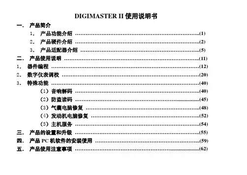
DIGIMASTER II使用说明书一.产品简介1.产品功能介绍 (1)2.产品硬件介绍 (2)3.产品适配器介绍 (5)二.产品使用说明 (11)1.器件编程 (12)2.数字仪表调校 (20)3.特殊功能 (40)(1)音响解码 (40)(2)防盗读码 (45)(3)气囊电脑修复 (48)(4)发动机电脑修复 (52)(5)主机服务 (54)三.产品的设置和升级 (55)四.产品PC机软件的安装使用 (59)五.产品使用注意事项 (62)一.产品简介:(一)产品功能介绍:仪器性能:1、本地操作:触摸屏、键盘2、远程操作:PC网上连接操作3、LCD:320*240 TFT 真彩屏4、端口:USB接口,适配器接口5、电源:12V DC6、存储卡:1G7、多语言版本选择功能特点:1、里程表调校2、音响解码3、气囊电脑修复4、原始密码读取5、ECU电脑编程6、网上升级7、支持各种最新软件8、手持机直接浏览图片本产品适用于汽车音响解码、读取防盗密码、气囊电脑修复、数字里程表调校、控制电脑的数据程序修复和存储器件的编程。
(二)DIGIMASTER II 硬件说明:(1). 主机说明1 显示屏:用于显示图片和操作步骤,触摸屏:用于操作仪器2 键盘:用于操作仪器3 电源指示灯:用于指示仪器的工作状态.4 电源开关:用于仪器电源接通和断开5 触摸笔:用于操作仪器的触摸屏6 电源插座:用于提供给仪器+12V的直流工作电源7 CF存储卡:用于存储程序和数据8 25针插座:用于仪器连接适配器的接口9 USB接口:用于仪器和计算机的USB接口通信(二)适配器和连接线说明1通用适配器(OBP) 适用于需要拆焊码片(EEPROM)的仪表、气囊电脑、音响、ECU等,如下图1免拆适配器(ICP) 适用于免拆线的93系列、25系列、35080码片( EEPROM),CPU的仪表、气囊电脑、音响、ECU 等,如下图2、下图3图1 图2 图3A 8芯连接排线适用于93系列,25系列,35080码片的免拆连接,如下图4图4 图5B CPU免拆线适用于摩托罗拉的CPU免拆连接,如上图53 NEC适配器(NEC-Adapter)(如下图1),适用于NEC系列的CPU免拆连接,NEC14针连接线(如下图2):配合NEC适配器(NEC-Adapter)使用,用于NEC系列的CPU免拆连接图1 图24 凌志LS400适配器(LS400-Adapter):适用于1992-1994年的凌志LS400的仪表IC(457C),如下图35 大切诺基适配器(Grand Cherokee) :适用于1999-2001年的大切诺基的仪表CPU,如下图4图3 图46 奔驰C/E CLASS适配器(C/E Class diagadp):适用于奔驰C/E CLASS中电子底盘为W203 /W211/W209的仪表如下图1图1 图27奔驰W203/W220适配器(W203/W220):适用于奔驰C/S CLASS中电子底盘为W203/W220(2002-2004年)的EIS 电脑模块的处理,如上图2图3 图48奔驰W211适配器(W211):适用于奔驰E CLASS电子底盘为W211(2002-2005年)的EIS电脑模块的处理,如上图39 宝马E65/E66适配器(E65/E66):用于宝马7系中电子底盘为E65/E66(2002-2004年)的CAS电脑模块的处理,如上图410 摩托罗拉9S12适配器(9S12):适用于宝马3/5/7系中电子底盘为E90/E60/E66(2005年后)CAS电脑模块的处理,奔驰S/E/C系列中电子底盘为W220/W211/W203(2005年后)的EIS电脑模块的处理等,如图下111 诊断座免拆适配器(Diagnostic Adapter):适用于大众、奥迪、奔驰、宝马等车款的免拆调校,如下图2图1 图2A 大众诊断座OBDII连接线:配合诊断座免拆适配器(Diagnostic Adapter)使用,适用于宝马、大众、奥迪K线通讯的车款,如下图3B 奔驰OBD连接线:配合诊断座免拆适配器(Diagnostic Adapter)使用,适用于奔驰SLK系列(2000年前)等车款免拆调校,如下图4图3 图4G 奔驰95S CLASS接头:配合诊断座免拆适配器(Diagnostic Adapter)使用,适用于奔驰95年S CLASS仪表插座连线调校12 宝马CAS OBDII免拆适配器(BMW CAS OBDII):适用于宝马7系中电子底盘为E65/E66(2002-2005年)CAS 电脑模块OBDII免拆调校(连接线采用“大众诊断座OBDII连接线”)二、产品使用说明DIGIMASTER II分为以下几大模块:器件编程读取和修改码片(EEPROM)和CPU数据仪表调校调校修复里程表特殊功能音响解码获取音响密码,解除音响锁定防盗读码读取防盗密码气囊修复恢复气囊电脑数据ECU修复修复ECU电脑的数据器件编程是特别针对汽车上使用的一些存储器EEPROM(俗称码片)和CPU(是存储汽车常用数据、密码的器件)的数据进行读出、显示、保存及改写的专用工具。
风雅音乐软件系列作曲大师2005(简谱版说明书)本手册免费发布,供免费用户学习本软件的基本使用方法,只包含完整版本的基础部分3-4章,正式版本有完整的使用手册。
武汉风雅软件有限公司目录第一章软件的安装及安装疑难 ............... 错误!未定义书签。
第二章软件的注册 ......................... 错误!未定义书签。
第三章基本使用方法 . (6)3.1 作曲大师整体印象 (6)3.2 使用作曲大师作简单的乐曲 (7)3.2.1 选择调性 (7)3.2.2 选择任意拍号 (8)3.2.3设置乐曲的速度、音色及音量 (9)3.2.4设置小节线的间隔 (9)3.2.5 开始创作 (10)3.2.6 输入音符与删除音符 (10)3.2.7 输入点的概念 (11)3.2.8 快捷键输入法 (11)3.2.9 音符的删除 (11)3.2.10 换页与增减行数 (11)3.2.11 撤销(UNDO)和恢复(REDO) (11)3.2.12添加升降号和附点 (12)3.2.13 添加和删除小节线 (13)3.2.14 组合音符 (13)3.2.15 连线的输入和删除 (13)3.2.16 添加重音记号、持续音记号 (14)3.2.17 添加歌词 (14)3.2.18 中间插入空行和歌词整体移动 (15)3.2.19 输入文本 (16)3.2.20 添加声部 (16)3.2.21添加连谱线和花括号 (17)3.3 运行与调试乐曲 (17)3.4 其他功能介绍 (17)3.4.1 保存歌曲 (17)3.4.2 调出旧曲 (18)3.4.3 转换MIDI (18)第四章新功能介绍 (20)4.1 MIDI键盘输入 (20)4.2 读取MIDI文件 (22)4.3 民族乐器和戏曲符号的输入 (22)4.4 多行和少行的混排 (22)4.5 圆滑线和延音线的自动检测 (23)4.6 首行缩进的调整 (24)4.7 多声部的音色标注法 (24)4.8 播放中加快和减慢速度 (24)4.9 简谱打击乐的鼓谱(节奏谱)的输入 (25)4.10 中间变节奏的标注 (26)4.11 中间变速度和音色的标注 (26)4.12 重复小节记号的输入、演奏和打印 (27)4.13 快速删除连线、高音点和增减时线 (27)4.14 插入和替换的输入方式 (28)4.15 歌词字体与音符字型以及版面调整 (28)4.16 主背景的保留和图文打印 (29)4.17 增时线间距调整 (30)4.18 16行排版版面的保存 (31)4.19 万能打印功能 (31)4.20 小节时间值自动判断以及自动组合音符 (31)4.21 打印总谱和分谱 (32)4.22 中间变换连谱属性 (32)4.23 带方框的小节号、小节号显示的间隔 (32)4.24 1024*768分辨率的支持 (33)4.25 向导功能 (33)4.26 四个倚音 (33)4.27 直接输出分谱 (34)4.28 拖动功能 (35)4.29 直接删除声部 (35)4.30 直接生成GIF格式的图片 (36)4.31 行距单独调整功能 (36)4.32 打印连续的页码 (37)第五章专题论述与经验技巧.................. 错误!未定义书签。
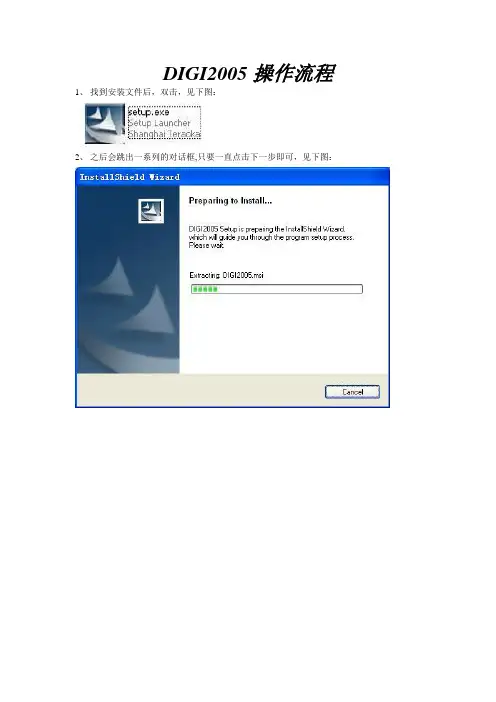
DIGI2005操作流程1、找到安装文件后,双击,见下图:2、之后会跳出一系列的对话框,只要一直点击下一步即可,见下图:3、安装完毕后,再桌面会有一个DIGI2005的快捷方程式。
见下图:3、双击后进入下面的界面:4、输入用户admin,确认。
进入下图:5、如果还没有注册的可以先点击确定,进入以下画面:6、进入后,我们首先要做的是建立新秤。
见下图;7、在设置栏中选中秤设置,进入后见下图:8、右键点击shanghai Teraoka, 出现下图:9、点击添加段,后出现以下画面:10、这个是根据你们店铺两台电子秤的称号设置的,只要按照我上图的输入就可以了。
设置好之后点击确定,见下图:11、右键点击1之后,见下图;12、点击添加秤,见下图:13、这个是根据你们店铺两台电子秤的称号设置的,只要按照我上图的输入就可以了。
设置好之后点击确定。
你们有两台秤,另一台是22号,只要重复上面的操作,把秤号和IP改一下就可以了。
14、秤建立好这后,我们最主要的就是要知道怎么样把资料导入到我们的DIGI2005中去。
见下图;15、点击工具中的数据转换,见下图:16、根据我上图所圈的设置,只要和我设置成一样就可以了。
接下来,就要看从你们软件导入的一个CSV文件了。
我们电子秤所需要的你们的一系列数据是这几项,商品编号,品名,单价,保质期,秤重或非秤重,有了这几项我们就可以把资料导入的软件里了。
如何设置见下图。
17、双击PLU编号,右边会跳出让你编辑的选项,在起始位置中输入你们导出来的CSV文件的PLU标号的列数,如果是第一列就在起始位置中输入1就可以了,要是是在第三列,那就在起始位置中输入3,点击保存。
再双击左边的商品编号见下图:18、在起始位置中输入你们CSV文件中的商品编号所在列,点击保存。
双击左边单价,见下图:19、在起始位置中输入CSV文件中所在列,点击保存。
双击左边的条码格式,见下图:20、在描述中选中你们所要的条码格式,在设置默认值中输入适合你们条码格式的编号,点击保存。

M05-MP3通用开发板说明书发明专利号:02112283.0(2006/4/27日最后修改)一、产品概述:M05—MP3通用开发板是奔流公司积多年数码语音产品之设计经验,充分吸收不同用户的建议和要求,全新设计开发的年度重点产品,具有众多创新优点:★采用成熟芯片及方案,确保性能稳定可靠。
本产品主要应用于工业环境,以高可靠性为设计之本。
系统设计有硬件看门狗电路,独创RESET端口外引、CPU-CLOCK信号、P/R忙信号、I2C接口使能信号等多重技术保障措施。
★支持播放64—256KBPS的各种MP3压缩比,音质与播放时间可弹性安排。
★采用英国Wolfson公司的高级DAC芯片,音质好,性噪比高。
★有标准、重低音、爵士、的士高、流行、古典等多种音效回放模式可选择。
★独创实时录音功能。
板上自带实时时钟芯片和电池,可进行实时录音记录。
可分别通过本板配套的液晶屏和PC机查看到录音文件的开始时间。
录音文件可以通过USB接口传送到PC机上保存,其录音文件格式支持在PC机上播放。
具有“HQ—高音质、LQ—低音质”两种录音模式选择。
★独创消防录音专用接口,可通过线路输入录音。
★板上设计有数字调谐FM收音机模组可选装。
★系统独创设计有通用I2C串行接口电路,可以很方便的与外部MCU连接控制。
且I2C接口命令丰富,涵盖所有MP3/录音/收音机等的常用命令。
★可支持多达几千个文件的播放。
★设计有功能齐全的键盘电路和大中文液晶显示电路,使用操作方便(选装)。
★0—9 数字键可定义为1-10段单键触发播放和顺序按入多位数字键后再“确认”键播放两种模式可选。
★有全曲播放1次、全曲循环N次、单曲循环N次、单曲播放1次、全曲浏览播放等多种歌曲回放模式可选。
★设计有USB1.1接口电路,以U盘格式存贮数据,速度快,使用方便。
在WINDOWS XP/2000下不需驱动软件支持。
★可支持16M-512M的NAAD FLASH。
并可支持16M-512M的SD卡。
VSS的简单工作原理●Microsoft的VSS 将所有的项目源文件(包括各种文件类型)以特有的方式存入数据库。
开发组的成员不能对该数据库中的文件进行直接的修改,而是由该版本管理器将该项目的源程序或是子项目的源程序拷贝到各个成员自己的工作目录下进行调试和修改,然后将修改后的项目文件作Checkin提交给VSS,由它进行综合更新。
●用户可以根据需要随时快速有效地共享文件。
文件一旦被添加进VSS,它的每次改动都会被记录下来,用户可以恢复文件的早期版本,项目组的其他成员也可以看到有关文档的最新版本,并对它们进行修改,VSS也同样会将新的改动记录下来。
客户端基本操作●1、创建项目●2、添加文件/文件夹●3、签入/签出,撤销签出,查看文件●4、创建工作目录●5、修改/编辑文件●6、移动文件/文件夹●7、共享文件/文件夹●8、拆分文件●9、删除/恢复文件●10、给文件打标签(lable)●11、获取历史版本●12、获取最新版本●13 、修改密码●14、打开、关闭数据库客户端基本操作1●创建项目(File->Create Project)a.选中要创建新文件夹的项目(上级文件夹)b.在file菜单中选中creat project;c.写入要添加的文件夹的名称,同时也可以在comment栏中为新建的文件夹添加备注;d.点击OK。
客户端基本操作2●添加文件1.add命令添加文件a.选中你要添加文件的文件夹;b.在fil菜单中选中add files;c.在文件列表中选中要添加的文件;如果要添加多个文件,可以使用CTRL键或SHIFT键,同时选中多个文件;d.点击add,同时可以在comment栏为你添加的文件夹做一个简单备注;e.点击OK。
●添加文件夹a.选中你要添加文件夹的项目(上级文件夹);b.在file菜单中选中add files;c.在文件夹列表中选中要添加的文件夹;d.点击add,同时可以在comment栏为你添加的文件夹做一个简单备注;e.如果你要连同子文件夹一起添加,选择Recursive;f.点击OK。
条码电子秤快速设置手册(20110106)一、托利多:1、设置秤号:代码→24681357*1*08*(清除后输入秤号)↓代码退出2、设置IP:代码→24681357*1*21*(清除后输入IP地址)↓(清除后输入子网掩码)↓↓↓(6次代码保存重新启动)3、四舍五入:代码→666666*02*1↓代码退出4、右移动小数一位(0不移动,1右移一位,2右移两位)代码→666666*18*1↓代码退出5、选择是否允许倒转功能代码→24681357*25*(4次↓)(0:否/ 1:是)(5次↓)代码退出6、测纸:代码→24681357*25*→(8次↓) →1(5次*)代码退出7、背景灯:代码↓↓代码(关闭)代码↑↑代码(打开)8、更改日期:代码→1*57*↓(日期)↓(时间)↓9、低于40G打印(金额不能小于0.1):代码→666666*23*1*二、寺冈SM80(在设置保存时候禁止断电)1、设置秤号:置零+141→135×→输入秤号(IP地址最后一组数字)→总计*打印→项目#代码2、设置IP:置零+3752→置零+0416→输入IP地址前三组数字→总计*打印→项目#代码3、四舍五入:置零+3752→置零+142→629×3→总计*打印→项目#代码4、右移动小数一位(0不移动,1移动一位)置零+3752→置零+142→676×1→总计*打印→项目#代码5、单价覆盖(1禁止改价,0允许改价【42所有,178单品】)置零+141→42×1→总计*打印→项目#代码置零+141→178×1→总计*打印→项目#代码三、寺冈SM100(在设置保存时候禁止断电)1、设置秤号:按四次【方式】键进入【Z模式】→置零+141→135×→输入秤号(IP地址最后一组数字)→总计*打印→项目#代码2、设置IP:按四次【方式】键进入【Z模式】→置零+0416→输入IP地址前三组数字→总计*打印→项目#代码3、四舍五入:按四次【方式】键进入【Z模式】→置零+3752→置零+142→629×4→总计*打印→项目#代码4、右移动小数一位(0不移动,1移动一位)按四次【方式】键进入【Z模式】→置零+3752→置零+142→676×1→总计*打印→项目#代码5、单价覆盖(1禁止改价,0允许改价【42所有,178单品】)按四次【方式】键进入【Z模式】→置零+141→42×1→总计*打印→项目#代码按四次【方式】键进入【Z模式】→置零+141→178×1→总计*打印→项目#代码6、保值期超99天(1禁止,0允许)按四次【方式】键进入【Z模式】→置零+141→142×0→总计*打印→项目#代码7、PLU码跟随含价条码(1禁止,0允许)按四次【方式】键进入【Z模式】→置零+141→273×1→总计*打印→项目#代码注:SM100秤标签“保质期”DIGI2005设置标签。
版權所有© 2010屬於技嘉科技股份有限公司保留所有權利Q2005系列筆記型電腦使用手冊初版:2010/12本手冊可引導您設定和使用全新Q2005™筆記型電腦。
本手冊資訊之正確性皆經過查核,如有變更恕不另行通知。
如果事先未獲得書面許可,不得以任何形式或電子、機械、照相、記錄等任何方式重製本手冊、儲存於檢索系統中或加以傳播。
商標GIGABYTE™為技嘉科技股份有限公司之註冊商標。
本手冊提及之所有其他品牌或產品名稱皆為其所屬公司之商標或註冊商標。
Microsoft®、MS-DOS、Windows®及Windows® Sound System皆為Microsoft Corporation之商標。
Intel®、Atom™皆為Intel Corporation之註冊商標。
繁體中文I 安全說明在使用您的Q2005系列筆記型電腦時,請遵守以下安全準則以保護您自己和您的筆記型電腦。
小心:使用筆記型電腦時,請勿長時間將電腦的底部直接接觸皮膚。
長時間使用後,熱量會累積在電腦底部。
若與皮膚持續接觸會造成不適感或灼傷。
• 當您將筆記型電腦從外箱取出後,請將包裝組件放置於幼童不易取得之處,以免誤食造成窒息。
• 請勿將物品壓在變壓器的電源線上,此外請將電源線置於安全處以避免將人絆倒或遭人踩踏。
使用電腦或為電池充電時,請將變壓器放置於通風處,如桌面或地板上。
請勿以紙張或其他物品覆蓋變壓器以免阻礙通風。
• 使用筆記型電腦時,務必保持散熱孔周邊至少10公分距離暢通。
• 請勿將任何物品插入筆記型電腦的散熱孔。
否則會造成短路,進而導致火災或觸電。
• 請勿用手觸摸或按壓液晶螢幕。
• 限使用筆記型電腦製造商隨附的變壓器和電池。
使用其他類型的電池或變壓器可能會讓發生火災或爆炸的風險提高。
• 電池的裝入方式不正確可能會導致爆炸。
• 若需更換電池時,限定使用製造商建議的相同或相容電池。
• 連接筆記型電腦與電源之前,請確認變壓器的額定電壓符合可用電源的電壓。