FresnelLenses 菲涅尔透镜原理
- 格式:pdf
- 大小:244.48 KB
- 文档页数:12
菲涅尔透镜的原理菲涅尔透镜是一种常见的光学元件,它是由一系列环状的凸透镜组成。
菲涅尔透镜的设计原理是基于菲涅尔透镜的麦克斯韦方程组。
菲涅尔透镜的主要功能是将光线聚焦到一个点上,从而产生放大效果。
下面将详细介绍菲涅尔透镜的原理和应用。
菲涅尔透镜的原理是基于光的折射现象。
当光线从一种介质传播到另一种具有不同折射率的介质中时,光线会发生折射。
根据斯涅尔定律,入射角和折射角之间有一个固定的关系。
菲涅尔透镜利用这种折射现象,通过改变光线的传播方向和聚焦效果来实现光的放大。
菲涅尔透镜的结构和传统的透镜有所不同。
传统的透镜是由一段连续的曲面组成,而菲涅尔透镜是由一系列环状的凸透镜组成。
这种结构的设计使得透镜更加轻薄和便于制造。
菲涅尔透镜的每一个环状凸透镜都有一个特定的曲率半径,使得光线在透镜内部发生折射后能够聚焦到一个点上。
菲涅尔透镜常用于光学仪器中,例如显微镜、望远镜和摄影镜头等。
在显微镜中,菲涅尔透镜可以将样品上的光线聚焦到物镜上,从而放大样品的细节。
在望远镜中,菲涅尔透镜可以将远处的物体光线聚焦到观察者的眼睛上,从而使得远处的物体看起来更大更清晰。
在摄影镜头中,菲涅尔透镜可以帮助摄影师将景物聚焦到感光元件上,从而得到清晰的照片。
除了光学仪器,菲涅尔透镜还可以应用于太阳能集热器。
太阳能集热器利用菲涅尔透镜的聚焦效果将太阳光线聚焦到一个小面积上,从而产生高温。
这种高温可以用于加热水或发电等应用。
菲涅尔透镜在太阳能领域的应用具有重要的意义,可以提高太阳能的利用效率。
菲涅尔透镜的设计和制造需要考虑多个因素,例如透镜的曲率半径、透镜的厚度和透镜的材料等。
这些因素会影响透镜的焦距和聚焦效果。
因此,在实际应用中需要根据具体的需求选择合适的菲涅尔透镜参数。
总结起来,菲涅尔透镜是一种基于光的折射现象的光学元件。
它通过改变光线的传播方向和聚焦效果来实现光的放大。
菲涅尔透镜广泛应用于光学仪器和太阳能集热器等领域。
在设计和制造菲涅尔透镜时,需要考虑多个因素,以满足具体的应用需求。
菲涅尔透镜(Fresnel lens) 是由聚烯烃材料注压而成的薄片,镜片表面一面为光面,另一面刻录了由小到大的同心圆,它的纹理是利用光的干涉及扰射和根据相对灵敏度和接收角度要求来设计的,透镜的要求很高,一片优质的透镜必须是表面光洁,纹理清晰,其厚度一般在1mm 左右,特性为面积较大,厚度薄及侦测距离远。
菲涅尔透镜作用有两个:一是聚焦作用,即将热释红外信号折射(反射)在PIR上,第二个作用是将探测区域内分为若干个明区和暗区,使进入探测区域的移动物体能以温度变化的形式在PIR上产生变化热释红外信号。
菲涅尔透镜,简单的说就是在透镜的一侧有等距的齿纹.通过这些齿纹,可以达到对指定光谱范围的光带通(反射或者折射)的作用.传统的打磨光学器材的带通光学滤镜造价昂贵。
菲涅尔透镜可以极大的降低成本。
典型的例子就是PIR(被动红外线探测器)。
PIR广泛的用在警报器上。
如果你拿一个看看,你会发现在每个PIR上都有个塑料的小帽子。
这就是菲涅尔透镜。
小帽子的内部都刻上了齿纹。
这种菲涅尔透镜可以将入射光的频率峰值限制到10微米左右(人体红外线辐射的峰值)。
成本相当的低。
菲涅耳透镜可以把透过窄带干涉滤光镜的光聚焦在硅光电二级探测器的光敏面上。
菲涅尔透镜由有机玻璃制成,不能用任何有机芤?如酒精等)擦拭。
除尘时可先用蒸馏水或普通净水冲洗,再用脱脂棉擦拭。
菲涅尔镜片是红外线探头的“眼镜”,它就象人的眼镜一样,配用得当与否直接影响到使用的功效,配用不当产生误动作和漏动作,致使用户或者开发者对其失去信心。
配用得当充分发挥人体感应的作用,使其应用领域不断扩大。
菲涅尔镜片是根据法国光物理学家FRESNEL发明的原理采用电镀模具工艺和PE(聚乙烯)材料压制而成。
镜片(0.5mm厚)表面刻录了一圈圈由小到大,向外由浅至深的同心圆,从剖面看似锯齿。
圆环线多而密感应角度大,焦距远;圆环线刻录的深感应距离远,焦距近。
红外光线越是靠进同心环光线越集中而且越强。
菲涅尔镜片的原理和应用1. 菲涅尔镜片的原理菲涅尔镜片是一种特殊的透镜,由法国物理学家奥古斯丁·让·菲涅尔设计并于19世纪初期发明。
菲涅尔镜片的主要原理是通过将透镜的表面分割成许多小的锯齿形区域,从而减小透镜的材料厚度和重量,同时保持透镜的光学性能。
菲涅尔镜片的锯齿形区域被称为菲涅尔环(Fresnel zone),每个菲涅尔环都有相同的光程差,因此可以将入射光的波前重新构建。
这种设计能够减小透镜的材料厚度,因此菲涅尔镜片相比传统透镜更轻薄,能够更好地适应超广角光线的收集。
2. 菲涅尔镜片的应用菲涅尔镜片由于其独特的设计,被广泛应用于各个领域。
2.1 太阳能光伏领域在太阳能光伏系统中,菲涅尔镜片常被用于聚光光伏系统。
菲涅尔镜片可以将来自太阳的光线进行聚焦,提高光伏电池的光吸收效率。
通过使用菲涅尔镜片,可以减小光伏电池的面积,并将光线集中到小面积的光伏电池上,从而提高太阳能光伏系统的发电效率。
2.2 舞台灯光领域在舞台灯光领域中,菲涅尔镜片常被用于灯光聚焦。
舞台灯光常常需要将光线聚焦到特定的区域,用于照亮舞台上的演员或特定的场景。
菲涅尔镜片的特殊设计使得它能够将灯光聚焦到较小的区域,提供明亮而集中的照明效果。
2.3 摄影领域在摄影领域中,菲涅尔镜片常被用于摄影灯光聚焦。
摄影师可以使用菲涅尔镜片的聚光效果,将光线准确地聚焦到被摄对象上,从而获得清晰而明亮的影像。
尤其在拍摄远距离或夜景时,菲涅尔镜片的聚光效果可以使摄影师获得更好的拍摄效果。
2.4 导航领域在导航领域中,菲涅尔镜片常被用于航海和航空领域的灯塔和灯浮。
菲涅尔镜片的设计能够将光线按照特定的方向进行聚焦和发射,从而提供远距离的引导和警示功能。
船只和飞机可以通过观察灯塔和灯浮上的菲涅尔镜片,确定自己的位置和航向,从而实现安全导航。
2.5 物理实验领域菲涅尔镜片在物理实验领域也有广泛的应用。
例如,在光波衍射实验中,菲涅尔镜片的光程差特性可以用来观察和研究波前的干涉和衍射现象。
菲涅尔透镜的原理及应用(国防科大理学院光学小组第六组)[摘要] 菲涅尔透镜多是由聚烯烃材料注压而成的薄片,镜片表面一面为光面,另一面刻录了由小到大的同心圆。
菲涅尔透镜的在很多时候相当于红外线及可见光的凸透镜,效果较好,但成本比普通的凸透镜低很多。
菲涅尔透镜可按照光学设计或结构进行分类。
菲涅尔透镜作用有两个:一是聚焦作用;二是将探测区域内分为若干个明区和暗区,使进入探测区域的移动物体能以温度变化的形式在PIR上产生变化热释红外信号。
[关键词] 菲涅尔透镜;原理;分类;应用;研究与发展状况本文主要从菲涅尔透镜的历史,基本原理,分类,作用,应用以及国内外的研究与发展状况等方面完整介绍了菲涅尔透镜的相关知识。
1.简介菲涅尔透镜(Fresnel lens),又称螺纹透镜,是由法国物理学家奥古斯汀·菲涅尔(Augustin·Fresnel)发明的,他在1822年最初使用这种透镜设计用于建立一个玻璃菲涅尔透镜系统——灯塔透镜。
菲涅尔透镜多是由聚烯烃材料注压而成的薄片,也有玻璃制作的,镜片表面一面为光面,另一面刻录了由小到大的同心圆,它的纹理是利用光的干涉及扰射和根据相对灵敏度和接收角度要求来设计的,透镜的要求很高,一片优质的透镜必须是表面光洁,纹理清晰,其厚度随用途而变,多在1mm左右,特性为面积较大,厚度薄及侦测距离远。
菲涅尔透镜菲涅尔透镜作用有两个:一是聚焦作用;二是将探测区域内分为若干个明区和暗区,使进入探测区域的移动物体能以温度变化的形式在PIR上产生变化热释红外信号。
菲涅尔透镜的在很多时候相当于红外线及可见光的凸透镜,效果较好,但成本比普通的凸透镜低很多。
多用于对精度要求不是很高的场合,如幻灯机、薄膜放大镜、红外探测器等。
2.菲涅尔透镜的历史通过将数个独立的截面安装在一个框架上从而制作出更轻更薄的透镜,这一想法常被认为是由布封伯爵提出的。
孔多塞(1743-1794)提议用单片薄玻璃来研磨出这样的透镜。
菲涅尔透镜介绍菲涅尔透镜 (Fresnel lens) ,又名螺纹透镜,一般由高透明材料注塑或压注而成的薄片,也有玻璃制作的,镜片表面一面为光面,另一面刻录了由小到大的同心圆,它的纹理是根据光的干涉及扰射以及相对灵敏度和接收角度要求来设计的。
透镜的要求很高。
一片优质的透镜必须表面光洁,纹理清晰,其厚度随用途而变,多在1-2mm左右,特性为面积大、厚度薄及侦测距离远。
菲涅尔透镜在很多时候相当于红外线及可见光的凸透镜,效果较好,但成本比普通的凸透镜低很多。
多用于对精度要求不是很高的场合,如投影机、薄膜放大镜、红外探测器及照明等。
使用普通的凸透镜,会出现边角变暗、模糊的现象,这是因为光的折射只发生在介质的交界面,凸透镜片较厚,光在玻璃中直线传播的部分会使得光线衰减。
如果可以去掉直线传播的部分,只保留发生折射的曲面,便能省下大量材料同时达到相同的聚光效果。
菲涅耳透镜就是采用这种原理的。
菲涅尔透镜看上去像一片有无数多个同心圆纹路的平板玻璃,却能达到凸透镜的效果,如果投射光源是平行光,汇聚投射后能够保持图像各处亮度的一致。
菲涅尔透镜的应用菲涅尔透镜应用于多个领域,包括:投影显示:菲涅尔投影电视,背投菲涅尔屏幕,高射投影仪,准直器;聚光聚能:太阳能用菲涅尔透镜,摄影用菲涅尔聚光灯,菲涅尔放大镜;航空航海:灯塔用菲涅尔透镜,菲涅尔飞行模拟;科技研究:激光检测系统等;红外探测:无源移动探测器;照明光学:汽车头灯,交通标志,光学着陆系统。
智能家居:安防系统探测器等我公司生产的菲涅尔镜,采用主要注塑和热压两种方式。
注塑菲涅尔透镜:设备是进口的高精密注塑机,主要生产小规格菲涅尔透镜(8吋以下),可以大规模提供需求。
热压菲涅尔透镜:设备是根据工艺需求自主设计制造的专用自动热压机。
热压的菲涅尔镜产品精度高,质量好,主要用在成像方面,产品尺寸规格3-10吋,也可以定制超大尺寸的产品。
外形由数控激光激光机切割,产品形状任意,可以根据客户需要选择定制。
1.菲涅尔透镜菲涅尔透镜 (Fresnel lens) ,又称螺纹透镜,是由法国物理学家奥古斯汀•菲涅尔(Augustin•Fresnel)发明的,他在1822年最初使用这种透镜设计用于建立一个玻璃菲涅尔透镜系统--灯塔透镜。
菲涅尔透镜多是由聚烯烃材料注压而成的薄片,也有玻璃制作的,镜片表面一面为光面,另一面刻录了由小到大的同心圆,它的纹理是利用光的干涉及扰射和根据相对灵敏度和接收角度要求来设计的,透镜的要求很高,一片优质的透镜必须是表面光洁,纹理清晰,其厚度随用途而变,多在1mm左右,特性为面积较大,厚度薄及侦测距离远。
菲涅尔透镜作用有两个:一是聚焦作用;二是将探测区域内分为若干个明区和暗区,使进入探测区域的移动物体能以温度变化的形式在PIR上产生变化热释红外信号。
菲涅尔透镜的在很多时候相当于红外线及可见光的凸透镜,效果较好,但成本比普通的凸透镜低很多。
多用于对精度要求不是很高的场合,如幻灯机、薄膜放大镜、红外探测器等。
2.菲涅尔透镜的历史通过将数个独立的截面安装在一个框架上从而制作出更轻更薄的透镜,这一想法常被认为是由布封伯爵提出的。
孔多塞(1743-1794)提议用单片薄玻璃来研磨出这样的透镜。
而法国物理学家兼工程师菲涅尔亦对这种透镜在灯塔上的应用寄予厚望。
根据史密森学会的描述,1823年,第一枚菲涅尔透镜被用在了吉伦特河口的哥杜昂灯塔(Phare de Cordouan)上;透过它发射的光线可以在20英里(32千米)以外看到。
苏格兰物理学家大卫·布儒斯特爵士被看作是促使英国在灯塔中使用这种透镜的推动者。
3.菲涅尔透镜的基本原理菲涅尔透镜的工作原理十分简单:假设一个透镜的折射能量仅仅发生在光学表面(如:透镜表面),拿掉尽可能多的光学材料,而保留表面的弯曲度。
从剖面看,其表面由一系列锯齿型凹槽组成,中心部分是椭圆型弧线。
每个凹槽都与相邻凹槽之间角度不同,但都将光线集中一处,形成中心焦点,也就是透镜的焦点。
菲尼尔透镜的工作原理
菲涅尔透镜是一种由法国物理学家奥古斯丁·让·菲涅尔于19世纪初发明的光学元件,其主要工作原理是利用透镜表面上的一系列刻槽或棱镜来改变光线的传播方向。
具体工作原理如下:
1. 菲涅尔透镜的表面被刻上一系列同心圆环或放射状的凸台,这些凸台由一系列直线形成,被称为菲涅尔环。
2. 入射到透镜上的光线,在经过菲涅尔环的凸台时,会受到折射和反射作用。
3. 这些折射和反射作用会使得光线改变传播方向,使其聚焦或发散。
4. 菲涅尔透镜的形状和刻槽的分布可以根据需要进行设计,以实现特定的光学功能,如聚焦光束或扩大视场。
5. 通过透镜的中央部分,光线可以以较原始的形式通过,而边缘部分的反射和折射则改变了边缘区域的光线传播,从而实现了所需的光学效果。
总而言之,菲涅尔透镜的工作原理是通过改变光线的传播方向来实现特定的光学功能,这一特点使其在一些特殊的应用中,如航海、监控、摄影等领域中得到广泛应用。
菲涅尔镜片的原理和应用菲涅尔镜片是红外线探头的“眼镜”,它就象人的眼镜一样,配用得当与否直接影响到使用的功效,配用不当产生误动作和漏动作,致使用户或者开发者对其失去信心。
配用得当充分发挥人体感应的作用,使其应用领域不断扩大。
菲涅尔镜片是根据法国光物理学家FRESNEL发明的原理采用电镀模具工艺和PE(聚乙烯)材料压制而成。
镜片(0.5mm厚)表面刻录了一圈圈由小到大,向外由浅至深的同心圆,从剖面看似锯齿。
圆环线多而密感应角度大,焦距远;圆环线刻录的深感应距离远,焦距近。
红外光线越是靠进同心环光线越集中而且越强。
同一行的数个同心环组成一个垂直感应区,同心环之间组成一个水平感应段。
垂直感应区越多垂直感应角度越大;镜片越长感应段越多水平感应角度就越大。
区段数量多被感应人体移动幅度就小,区段数量少被感应人体移动幅度就要大。
不同区的同心圆之间相互交错,减少区段之间的盲区。
区与区之间,段与段之间,区段之间形成盲区。
由于镜片受到红外探头视场角度的制约,垂直和水平感应角度有限,镜片面积也有限。
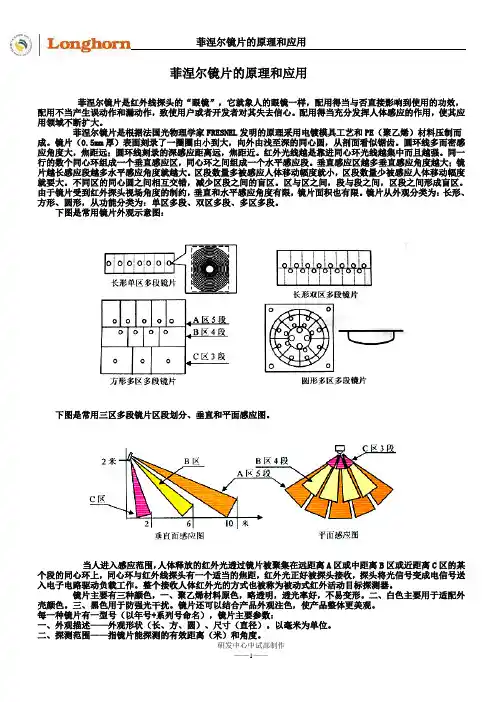
镜片从外观分类为:长形、方形、圆形,从功能分类为:单区多段、双区多段、多区多段。
下图是常用镜片外观示意图:下图是常用三区多段镜片区段划分、垂直和平面感应图。
当人进入感应范围,人体释放的红外光透过镜片被聚集在远距离A区或中距离B区或近距离C区的某个段的同心环上,同心环与红外线探头有一个适当的焦距,红外光正好被探头接收,探头将光信号变成电信号送入电子电路驱动负载工作。
整个接收人体红外光的方式也被称为被动式红外活动目标探测器。
镜片主要有三种颜色,一、聚乙烯材料原色,略透明,透光率好,不易变形。
二、白色主要用于适配外壳颜色。
三、黑色用于防强光干扰。
镜片还可以结合产品外观注色,使产品整体更美观。
每一种镜片有一型号(以年号+系列号命名),镜片主要参数:一、外观描述——外观形状(长、方、圆)、尺寸(直径)。
以毫米为单位。
二、探测范围——指镜片能探测的有效距离(米)和角度。

菲涅尔透镜最高温度引言菲涅尔透镜是一种特殊的光学元件,常用于聚焦太阳能以产生高温。
本文将探讨菲涅尔透镜的原理、设计和使用,以及如何提高其最高温度。
菲涅尔透镜原理菲涅尔透镜是由法国物理学家奥古斯丁·让·菲涅尔于19世纪提出的。
它由一系列环形凸透镜组成,每个凸透镜都只有一小部分曲面。
这种设计使得菲涅尔透镜具有与传统透镜相比更大的有效面积。
当太阳光通过菲涅尔透镜时,它会被聚焦在一个点上,从而产生高温。
这是因为凸面将光线汇聚到一个小区域内,使能量密度增加。
利用这个原理,可以将太阳能转化为热能,并应用于多种领域,如太阳能发电、太阳能热水器等。
菲涅尔透镜设计要实现较高的最高温度,需要考虑以下几个关键因素:1. 材料选择菲涅尔透镜通常由透明的材料制成,如玻璃或塑料。
为了提高最高温度,可以选择具有较高抗热性的特殊材料,如石英玻璃或高温塑料。
2. 凸透镜形状凸透镜的形状对最终聚焦效果有很大影响。
通常情况下,透镜的曲率半径越小,聚焦效果越好。
因此,在设计中可以尝试使用更陡峭的曲面来提高聚焦效果。
3. 透镜尺寸菲涅尔透镜的直径和厚度也会影响最高温度。
较大直径的透镜可以接收更多太阳光,并将其聚焦在一个小区域内。
而较厚的透镜可以更好地吸收和保持热量。
提高菲涅尔透镜最高温度的方法除了上述设计考虑因素外,还有几种方法可以进一步提高菲涅尔透镜的最高温度:1. 表面处理通过在菲涅尔透镜表面施加特殊涂层,可以增加光的吸收率和热导率,从而提高最高温度。
例如,使用具有较高吸收率的黑色涂层可以增加光能的转化效率。
2. 配合其他设备将菲涅尔透镜与其他设备结合使用,如对流散热系统或热能储存装置,可以进一步提高最高温度。
这些设备可以帮助透镜更好地吸收和利用热能。
3. 调整聚焦距离通过调整菲涅尔透镜与聚焦点之间的距离,可以改变聚焦效果。
通过找到最佳聚焦距离,可以使透镜在不同条件下实现最高温度。
应用领域菲涅尔透镜的高温特性使其在许多领域得到应用:1. 太阳能发电将菲涅尔透镜用于太阳能发电系统中,可以将太阳光聚焦在光伏电池上,从而提高发电效率。
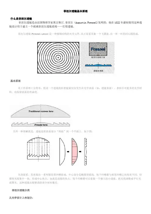
菲涅尔透镜基本原理什么是菲涅尔透镜菲涅尔透镜是由法国物理学家奥古斯汀.菲涅尔(Augustin.Fresnel)发明的,他在1822年最初使用这种透镜设计用于建立一个玻璃菲涅尔透镜系统——灯塔透镜。
菲涅尔透镜(Fresnel Lense)是一种微细结构的光学元件,从正面看其象一个飞镖盘,由一环一环的同心圆组成。
基本原理其工作原理十分简单:假设一个透镜的折射能量仅仅发生在光学表面(如:透镜表面),拿掉尽可能多的光学材料,而保留表面的弯曲度。
另外一种理解就是,透镜连续表面部分“坍陷”到一个平面上。
如下图:从剖面看,其表面由一系列锯齿型凹槽组成,中心部分是椭圆型弧线。
每个凹槽都与相邻凹槽之间角度不同,但都将光线集中一处,形成中心焦点,也就是透镜的焦点。
每个凹槽都可以看做一个独立的小透镜,把光线调整成平行光或聚光。
这种透镜还能够消除部分球形像差。
菲涅尔透镜分类从光学设计上来划分:正菲涅尔透镜:光线从一侧进入,经过菲涅尔透镜在另一侧出来聚焦成一点或以平行光射出。
焦点在光线的另一侧,并且是有限共轭。
这类透镜通常设计为准直镜(如投影用菲涅尔透镜,放大镜)以及聚光镜(如太阳能用聚光聚热用菲涅尔透镜。
负菲涅尔透镜:和正焦菲涅尔透镜刚好相反,焦点和光线在同一侧,通常在其表面进行涂层,作为第一反射面使用。
从结构上划分:圆形菲涅尔透镜菲涅尔透镜阵列,柱状菲涅尔透镜,线性菲涅尔透镜,衍射菲涅尔透镜,菲涅尔反射透镜,菲涅尔光束分离器和菲涅尔棱镜。
总结菲涅尔透镜是一种应用十分广泛的光学元件,其设计和制造设计到多个技术领域,包括光学工程,高分子材料工程,CNC 机械加工,金刚石车削工艺,镀镍工艺;模压、注塑、浇铸等制造工艺。
国内拥有设计及制造能力的公司不多,成都菲斯特科技有限公司从1999年开始致力于菲涅尔透镜的研究,开发和生产,拥有先进的大型单点金刚石超精密模具加工设备和多种生产手段,擅长大型、高精密菲涅尔透镜的设计、开发和生产,同时是成都光电显示工程技术中心的依托单位。
菲涅尔透镜原理菲涅尔透镜原理也称作“透镜理论”,是英国物理学家威廉菲涅尔所提出的一套物理惯性参数模型。
它强调了物体在空间上运动的概念,能够准确描述物体在多维空间中每秒实现的总运动量。
它通过引入运动惯性,明确物体在空间移动时的路径,从而大大简化了物体移动的描述过程。
菲涅尔透镜原理是一套基于动量定理的物理模型,最早由威廉菲涅尔于1887年在《哲学》杂志中提出。
威廉菲涅尔将动量定理的经典立场解释为,物体在实现总的空间移动过程中,会遵循一条以其初始动量为半径的圆弧轨迹。
他对这一观点进行了更为准确的理论分析,以求出它在多维空间中的正确表达形式。
菲涅尔透镜原理极大地改变了物理学家对物体运动的认识,它强调了物体的总运动量的重要性,从而明确了物体的路径和运动趋势,使物体的运动可以得到更加准确地描述。
菲涅尔透镜原理对物理学研究也具有重要的意义,它的发现为物体运动的各种实际应用提供了坚实的理论基础,如航天飞行中的抛物线外轨道规划,全球定位系统(GPS)等。
菲涅尔透镜原理可以从动量定理的角度来理解,它表明物体在空间中的运动不受其初始动量的大小影响,而只受其初始动量的角度的影响。
因此,菲涅尔透镜原理被认为可以用来完善物体在运动中的时空关系,让我们能够在物体运动中更准确地描述物体的状态。
菲涅尔透镜原理强调了空间运动中物体的总运动量,但它也有另外一个重要的作用,就是它说明宇宙中物体的运动轨迹受到多个宇宙环境因素(如重力场、磁场、电场等)的共同作用,从而让运动更加复杂。
在菲涅尔透镜原理的指导下,科学家用更为准确的计算来描述物体的运动轨迹,从而使准确的轨迹图表明物体在太空中的定位和运动状态。
菲涅尔透镜原理在影响着物理学,航天学,空间科学和天文学等多个领域的发展,成为了包括实验物理学,天体力学,应用力学等多种学科的研究基础。
它的提出为物体在太空中的定位和运动提供了可行的理论框架,也为物体进行多维空间移动提供了有效的参考。
综上所述,菲涅尔透镜原理对物理学和各个应用领域都具有巨大的影响,它明确了物体在空间上运动的概念,可以更准确地描述物体移动的过程,从而在技术领域也发挥着重要的作用。
菲涅尔透镜原理菲涅尔透镜原理是一种光学装置,它利用反射原理,将光束聚焦到一点上,产生一个“点”图像。
这种装置的最早的想法出现在17世纪的英国物理学家菲涅尔发明的“理想透镜”上,当时他发明了一种具有聚焦和镇定作用的透镜,并尝试将其应用于发现太阳上细小物体的光谱表。
但是,他没有成功,因为当时技术上不能够准确控制这种装置的反射和聚焦。
直到20世纪,才有科学家成功地将这种装置应用到发现卫星的视觉探测和远距离的精确定位中。
菲涅尔透镜原理的基本原理是,在一个封闭的空间中,通过一种反射面将光束聚焦到一点上,形成非常有解剖力和超高分辨率的图像,使得精细结构完全可见。
其中反射面有两类,一类反射面是组成反射面的体素,由镜片、菲涅尔环或凹面组成,有利于收集从物体反射回来的光;另一类是通过反射将光线聚焦到一点上的反射面,利用物理规律,利用光的反射和折射,将光折射到指定的焦点上。
菲涅尔透镜的特点是它能够将光束集中到一点,从而产生超高分辨率的图像,而不会出现光圈散射。
它具有十分准确的聚焦能力,仅仅需要微小的变化就可以聚焦到一个小点,这使得它能够捕捉到细微的结构或细小的物体,从而拓展了观测能力的范围。
菲涅尔透镜原理的应用非常广泛,它可以用来捕捉微小的细节,甚至可以捕捉距离几十米乃至更远的物体图像。
它还可以用来收集极小的物体,如细颗粒、细菌和病毒,从而探测病毒的特征、监测环境和病毒的变化,有助于表征细胞和活体细胞特征。
它还可用于火箭发射、卫星观测、太阳能发电等方面,是一项重要的科技发明,为人类文明发展发挥着重要作用。
菲涅尔透镜原理是一项伟大的发明,它为当今科学技术发展起到了至关重要的作用。
它不仅能够提供高解剖力和超高分辨率的图像,还能够将光束集中在一点,捕捉到细小的结构,拓展人类的观测能力和感知范围,是科学研究的重要工具。
菲涅尔透镜的原理菲涅尔透镜是一种非球面透镜,由法国物理学家奥古斯丹·菲涅尔在19世纪中期发明。
相比于传统的球面透镜,菲涅尔透镜具有较短的焦距和较大的视场,被广泛应用于光学仪器、投影设备和摄影领域。
它的工作原理基于菲涅尔公式和折射定律。
菲涅尔透镜的结构由一系列圆环状的凹面透镜组成,每个凹面透镜都由许多狭缝组成。
这些狭缝使透镜表面呈现出扇形状的凹面,从而产生透镜所需的透镜效果。
菲涅尔透镜的工作原理可以通过以下步骤进行解释:1. 入射光线通过菲涅尔透镜的表面。
由于透镜的凹面由多个狭缝组成,光线在每个狭缝上都会发生折射。
2. 每个狭缝上的折射角度根据折射定律计算。
根据折射定律,入射角和折射角之间的关系可以表示为:n1*sinθ1 = n2*sinθ2,其中n1和n2分别为光线在空气和透镜材料中的折射率,θ1和θ2为入射角和折射角。
3. 由于每个狭缝的折射角度不同,因此入射光线会被分散成不同的角度。
这些被分散的光线将汇集在一个焦点上,形成清晰的图像。
菲涅尔透镜的优点之一是它的平行光束可以在透镜的大部分表面上聚焦。
这使得菲涅尔透镜能够有效地提供高质量的成像。
此外,菲涅尔透镜相对于传统的球面透镜具有更短的焦距和更大的视场。
这使得它在一些特定应用中更加理想,如投影设备和广角摄影。
菲涅尔透镜的制造过程相对简单,但仍然需要高精度的工艺来保证透镜表面的凹面精度和平整度。
制造菲涅尔透镜的主要步骤包括:先制作一个母模型,然后使用电火花加工或其他方法在透明材料上重复反复复制凹面,最后进行光学加工和抛光来提高透镜表面的质量。
总而言之,菲涅尔透镜的原理是利用多个狭缝上的折射来聚焦入射光线。
它相对于传统的球面透镜具有较短的焦距和较大的视场,因此在光学仪器、投影设备和摄影领域有广泛的应用。
但是,由于制造过程相对复杂,菲涅尔透镜的制造和加工也需要高精度和高质量的工艺来确保透镜的性能。
菲涅爾鏡片的原理和應用菲涅爾鏡片是紅外線探頭的“眼鏡”,它就象人的眼鏡一樣,配用得當與否直接影響到使用的功效,配用不當產生誤動作和漏動作,致使用戶或者開發者對其失去信心。
配用得當充分發揮人體感應的作用,使其應用領域不斷擴大。
菲涅爾鏡片是根據法國光物理學家FRESNEL發明的原理採用電鍍模具工藝和PE(聚乙烯)材料壓制而成。
鏡片(0.5mm厚)表面刻錄了一圈圈由小到大,向外由淺至深的同心圓,從剖面看似鋸齒。
圓環線多而密感應角度大,焦距遠;圓環線刻錄的深感應距離遠,焦距近。
紅外光線越是靠進同心環光線越集中而且越強。
同一行的數個同心環組成一個垂直感應區,同心環之間組成一個水準感應段。
垂直感應區越多垂直感應角度越大;鏡片越長感應段越多水準感應角度就越大。
區段數量多被感應人體移動幅度就小,區段數量少被感應人體移動幅度就要大。
不同區的同心圓之間相互交錯,減少區段之間的盲區。
區與區之間,段與段之間,區段之間形成盲區。
由於鏡片受到紅外探頭視場角度的制約,垂直和水準感應角度有限,鏡片面積也有限。
鏡片從外觀分類為:長形、方形、圓形,從功能分類為:單區多段、雙區多段、多區多段。
下圖是常用鏡片外觀示意圖:下圖是常用三區多段鏡片區段劃分、垂直和平面感應圖。
當人進入感應範圍,人體釋放的紅外光透過鏡片被聚集在遠距離A區或中距離B區或近距離C區的某個段的同心環上,同心環與紅外線探頭有一個適當的焦距,紅外光正好被探頭接收,探頭將光信號變成電信號送入電子電路驅動負載工作。
整個接收人體紅外光的方式也被稱為被動式紅外活動目標探測器。
鏡片主要有三種顏色,一、聚乙烯材料原色,略透明,透光率好,不易變形。
二、白色主要用於適配外殼顏色。
三、黑色用於防強光幹擾。
鏡片還可以結合產品外觀注色,使產品整體更美觀。
每一種鏡片有一型號(以年號+系列號命名),鏡片主要參數:一、外觀描述——外觀形狀(長、方、圓)、尺寸(直徑)。
以毫米為單位。
二、探測範圍——指鏡片能探測的有效距離(米)和角度。
菲涅尔透镜原理
菲涅尔透镜是一种特殊的透镜,它是由法国物理学家奥古斯丁·菲涅尔发明的,用于聚光和集光。
菲涅尔透镜原理的核心是通过透镜的表面微结构,将光线聚焦或散射,从而实现光学器件的功能。
在本文中,我们将深入探讨菲涅尔透镜的原理及其应用。
首先,菲涅尔透镜的原理是基于光的折射和反射。
透镜的表面被分成许多小的
圆环形凸起,这些凸起能够使光线在经过透镜时发生折射,从而改变光线的传播方向。
这种微结构的设计使得菲涅尔透镜能够更有效地聚光或散射光线,相比于普通透镜具有更高的光学性能。
其次,菲涅尔透镜的应用非常广泛。
在光学仪器中,菲涅尔透镜常被用于聚光,例如在汽车大灯、探照灯和航空灯等光源中,通过菲涅尔透镜的设计,可以使光线更加集中和均匀,提高照明效果。
此外,菲涅尔透镜还被广泛应用于太阳能领域,用于集光聚焦太阳能发电,提高太阳能利用效率。
除此之外,菲涅尔透镜还在摄影和摄像领域有着重要的应用。
在摄影镜头和摄
像镜头中,菲涅尔透镜的设计能够有效地改善镜头的光学性能,提高成像质量。
同时,菲涅尔透镜还可以用于虚拟现实设备和头盔显示器中,通过其特殊的光学设计,实现更清晰、更真实的图像显示效果。
总的来说,菲涅尔透镜原理是基于光的折射和反射,通过透镜表面的微结构实
现光线的聚光和集光。
菲涅尔透镜在照明、太阳能利用、摄影和虚拟现实等领域都有着重要的应用价值,其特殊的光学设计能够有效地改善光学器件的性能,提高其使用效果。
希望本文能够帮助读者更加深入地了解菲涅尔透镜原理及其应用,为相关领域的研究和实践提供一定的参考价值。
菲涅尔聚光灯的工作原理
菲涅尔聚光灯的工作原理是利用菲涅尔透镜的特殊结构将光线聚焦,以实现强光集中的效果。
菲涅尔透镜是一种特殊设计的透镜,它由许多非常薄的环状凹面组成。
这些凹面可以看作是一系列圆锥形透镜的截面。
相比于传统的透镜,菲涅尔透镜的主体部分要薄得多,这使得它可以更轻便、更薄,并且更容易制造。
当光线通过菲涅尔透镜时,透镜的表面凹面会改变光线的传播方向。
凹面会使入射光线在垂直于透镜表面方向上聚焦,从而形成一个强光束。
这个改变传播方向的效果相当于将平行光线聚集到一个点上,使得光线变得更加集中。
菲涅尔聚光灯中的光源通常是氙气灯或者LED灯,它会产生大量的平行光线。
这些光线通过菲涅尔透镜后,会被聚焦并形成一个强烈的、集中的光束。
由于聚光灯可以将光线聚焦到较远的距离,因此在舞台照明、灯光效果设计以及搜索和救援等领域得到广泛应用。
总之,菲涅尔聚光灯的工作原理是利用菲涅尔透镜的特殊结构将平行光线聚焦,形成一个强光束。
The Fresnel LensCenturies ago, it was recognized that the contour of the refracting surface of a conventional lens defines its focusing properties. The bulk of material between the refracting sur-faces has no effect (other than increasing absorption losses) on the optical properties of the lens. In a F resnel (point focus) lens the bulk of material has been reduced by the extraction of a set of coaxial annular cylinders of material, as shown in Figure 1. (Positive focal length Fresnel lenses are almost universally plano-convex.) The contour of the curved surface is thus approximated by right circular cylindrical portions, which do not contribute to the lens’ optical proper-ties, intersected by conical portions called “grooves.” Near the center of the lens, these inclined surfaces or “grooves”are nearly parallel to the plane face; toward the outer edge, the inclined surfaces become extremely steep, especially for lenses of low f–number. The inclined surface of each groove is the corresponding portion of the original aspheric surface, translated toward the plano surface of the lens; the angle of each groove is modified slightly from that of the original aspheric profile to compensate for this translation.The earliest stepped-surface lens was suggested in 1748by Count Buffon, who proposed to grind out material from the plano side of the lens until he was left with thin sections of material following the original spherical surface of the lens, as shown schematically in F igure 2a). Buffon’s work was followed by that of Condorcet and Sir D. Brewster, both of whom designed built-up lenses made of stepped annuli. The aspheric Fresnel lens was invented in 1822 by Augustin Jean F resnel (1788–1827), a F rench mathematician and physicist also credited with resolving the dispute between the classical corpuscular and wave theories of light through his careful experiments on diffraction. Fresnel’s original lens was used in a lighthouse on the river Gironde; the main innovation embodied in Fresnel’s design was that the center of curvature of each ring receded along the axis according to its distance from the center, so as practically to eliminate spherical aberration. Fresnel’s original design, including the spherical-surfaced central section, is shown schematically in Figure 2b). The early Fresnel lenses were cut and polished in glass – an expensive process, and one limited to a few large grooves. Figure 3 shows a Fresnel lens, constructed in this way, which is used in the lighthouse at St Augustine, Florida, USA. The large aperture and low absorption of F resnel lenses were especially important for use with the weak lamps found in lighthouses before the invention of high-brightness light sources in the 1900s. The illustrated system is catadioptric: the glass rings above and below the Fresnel lens band in the center of the light are totally-internally-reflecting prisms, which serve to collect an additional frac-tion of the light from the source. The use of catadioptric sys-tems in lighthouses was also due to Fresnel.Until the 1950’s, quality Fresnel lenses were made from glass by the same grinding and polishing techniques used in 1822. Cheap Fresnel lenses were made by pressing hot glass into metal molds; because of the high surface tension of glass, Fresnel lenses made in this way lacked the necessary detail, and were poor indeed.In the last forty years or so, the advent of optical-quality plastics, compression and injection molding techniques,Figure 1 Construction of a Fresnel lens from its correspond-ing asphere. Each groove of the Fresnel lens is asmall piece of the aspheric surface, translated to-ward the plano side of the lens. The tilt of each sur-face must be modified slightly from that of theoriginal portion of aspheric surface, in order tocompensate for the translation.Figure 2 Early stepped–surface lenses. In both illustrations the black area is material, and the dashed curvesrepresent the original contours of the lenses. a)shows the lens suggested by Count Buffon (1748),where material was removed from the plano sideof the lens in order to reduce the thickness. b)shows the original lens of Fresnel (1822), the cen-tral ring of which had a spherical surface. InFresnel’s lens, the center of curvature of each ringwas displaced according to the distance of thatring from the center, so as to eliminate sphericalaberration.a)b)© Copyright Fresnel Technologies, Inc. 20032© Copyright Fresnel Technologies, Inc. 20033and computer-controlled machining have made possible the manufacture and wide application of F resnel lenses of higher optical quality than the finest glass F resnel lenses.Modern computer-controlled machining methods can be used to cut the surface of each cone precisely so as to bring all paraxial rays into focus at exactly the same point, avoid-ing spherical aberration. Better still, newer methods can be used to cut each refracting surface in the correct aspheric contour (rather than as a conical approximation to this con-tour), thus avoiding even the width of the groove (typically 0.1 to 1 mm) as a limit to the sharpness of the focus. Even though each groove or facet brings light precisely to a focus,the breaking up of the wavefront by the discontinuous sur-face of a F resnel lens degrades the visible image quality.Except in certain situations discussed later, Fresnel lenses are usually not recommended for imaging applications in the visible light region of the spectrum.The characteristics of the aspheric “correction”The grinding and polishing techniques used in the manufac-ture of conventional optics lead to spherical surfaces. Spher-ical surfaces produce optics with longitudinal spherical aberration, which occurs when different annular sections of the optic bring light rays to a focus at different points along the optical axis. This phenomenon is illustrated for a positive focal length, plano-convex conventional lens in Figure 4 (in all optical illustrations in this brochure, light is taken to propagate from left to right). The lens illustrated is a section of a sphere with 1" (25 mm) radius of curvature, 1.6"(36 mm) in diameter; the index of refraction of the material is 1.5, typical both for optical glasses and for our plastics materials. The focal length of the illustrated lens is thus 2"(50 mm), and the aperture is /1.3. As is evident from the figure, the longitudinal spherical aberration is very strong.Single-element spherical lenses are typically restricted to much smaller apertures (higher –numbers) than this,because longitudinal spherical aberration of the magnitude shown in Figure 4 is generally unacceptable. Figure 5 shows an aspheric lens of the same focal length and –number;note that the surface contour is modified from the spherical profile in such a way as to bring rays passing through all points on the lens to a focus at the same position on the opti-cal axis. A lens made with the aspheric profile illustrated in Figure 5, therefore, exhibits no longitudinal spherical aber-ration for rays parallel to the optical axis.Since Fresnel lenses are made from the beginning to the correct aspheric profile, the notion of “correcting for spheri-cal aberration” is not meaningful for F resnel lenses. The lenses are more accurately characterized as “free from spherical aberration.” The combination of the aspheric sur-face (which eliminates longitudinal spherical aberration)and the thinness of the lens (which substantially reduces both absorption losses in the material and the change of those losses across the lens profile) allows F resnel lenses with acceptable performance to be made with very large apertures. In fact, F resnel lenses typically have far larger apertures (smaller –numbers) than the /1.3 illustrated in Figure 4.Figure 6 compares an aspheric plano-convex lens with an aspheric F resnel lens (the F resnel lens’ groove structure isf f f f f Figure 3 The light from the St Augustine, Florida (USA) light-house, showing the glass Fresnel optical system used in the lighthouse. The optical system is about 12 feet (3.5 m) tall and 7 feet (2 m) in diameter.Figure 4Illustration of longitudinal spherical aberration.The rays shown were traced through an /1.3 spherical-surface lens; the focus is evidentlyspread out over a considerable distance along theoptical axis.f© Copyright Fresnel Technologies, Inc. 20034tive focal length (EFL), quential, so that the Fresnel lens.focus. (This type of F application and reversed.for a given focal length tion (where object distances, i.e. the conjugates), and are found to be and for the conjugate ratio 3:1. Even though a lens may be designed for conjugates in some particular ratio, it can be used at other finite conjugate ratios as well. The error introduced is usually reasonably small.Fresnel lenses are normally fabricated so that they are correct for the case of grooves toward the collimated beam,plano side toward the focus (grooves “out”). They can, how-ever, be fabricated so that they are correct for the case of grooves toward the focus, plano side toward the collimated beam (grooves “in”). In this case, there is no refraction at all on the plano side for a collimated beam traveling parallel to the optical axis. In the grooves “out” case, both surfaces refract the light more or less equally. The case of grooves toward the collimated beam (“out”) is the optically preferred case. The main difference is that in the grooves “in” case, the grooves at the outer periphery of the lens are canted at muchf f f 1f ⁄1i ⁄1o ⁄+=i 4f 4f 3⁄ Figure 6 Comparison between an aspheric conventionallens and an aspheric Fresnel lens, illustrating the optical quantities discussed in the text.smaller angles to the plano surface than they would be in spherical or grooves “out” lenses. Because the angles made with the plano surface are relatively small toward the periphery of the lens, any small warpage or tilt of the lens surface, or any small deviation of a light ray from parallelism with the optical axis, leads to a very large deviation from the ideal in the angle between the light ray and the lens surface.These errors lead directly to a decrease in the collection effi-ciency of a grooves “in” lens relative to a grooves “out” lens of the same focal length and –number.A third case which is sometimes encountered is that of a Fresnel lens which is correct for grooves “out,” used with its grooves toward the focus (grooves “out” turned groovesf© Copyright Fresnel Technologies, Inc. 20035for angles of intersection between a light ray and the normalto a surface larger than the critical angle = ,where the ray is traveling from a medium of index of refrac-tion into a medium of index of refraction . It is evident that total internal reflection only occurs for , since in the case is greater than π /2 and therefore not physically meaningful.) This phenomenon makes the portion of a grooves “out” lens turned grooves “in” lens past about /1 useless. The phenomenon is easily observed as an appar-ent “silvering” of the outer portion of a grooves “out” lens when its grooves are turned to face the shorter conjugate.Total internal reflection does not occur for grooves “out”lenses used in their correct orientation because the only large-angle intersection between the light and the lens sur-face occurs at a transition from low to high refractive index.MaterialsOur standard materials for visible light applications are acrylic, polycarbonate and rigid vinyl. These materials are suitable for some near infrared applications as well, as dis-cussed later in this brochure. Figure 9 shows useful transmis-sion ranges for a variety of plastics materials. Materials suitable for infrared applications are described in detail in our POLY IR® brochure.The first step in choosing a material is to match the mate-rial to the spectral domain of the application. Other consid-erations include thickness, rigidity, service temperature,weatherability, and other physical properties listed in the table of properties on the next page.AcrylicOptical quality acrylic is the most widely applicable mate-rial, and is a good general-purpose material in the visible. Its transmittance is nearly flat and almost 92% from the ultravi-olet to the near infrared; acrylic may additionally be speci-fied to be UV transmitting (UVT acrylic) or UV filtering (UVF acrylic). The transmittance of our standard acrylic materials between 0.2 µm and 2.2 µm is shown in F igure 10 for a thickness of 1/8" (3.2 mm). Standard acrylic thicknesses are 0.060" (1.5 mm), 0.090" (2.3 mm), and 0.125" (3.2 mm). Rigid vinylRigid vinyl has a number of characteristics which make it both affordable and very suitable for certain applications. It has a high index of refraction; it is reasonably inexpensive;and it can be die-cut. However, polycarbonate has very sim-ilar properties, without the problems associated with rigid vinyl, and its use is encouraged over that of rigid vinyl in new applications. Rigid vinyl has about the same tempera-ture range as acrylic and is naturally fire-retardant. The trans-mittance of rigid vinyl between 0.2 µm and 2.5 µm is shown in F igure 11 for a nominal thickness of 0.030" (0.76 mm).Standard thicknesses for rigid vinyl are 0.010" (0.25 mm),0.015" (0.38 mm), 0.020" (0.51 mm), and 0.030" (0.76 mm). PolycarbonatePolycarbonate is spectrally similar to acrylic, but is useful at higher temperatures and has a very high impact resistance.The transmittance of polycarbonate between 0.2 µm and 2.2 µm is shown in Figure 12 for a nominal thickness of 1/8"θc sin –1n n '⁄()n n 'n 'n >n 'n <θc f Figure 7 Illustration of the strong asymmetry of the asphericFresnel lens. The illustrated lens is correct for the grooves facing the longer conjugate (grooves “out”). When it is turned around so that thegrooves face the shorter conjugate (grooves “out” turned grooves “in”), on-axis performance suffers. As discussed in the text, however, in the case where the grooves must face the shorter conjugate, a grooves “out” lens turned grooves “in” has some advantages over a lens correct for grooves “in.”Figure 8 Aspheric Fresnel lens correct for the grooves facingthe shorter conjugate (grooves “in”).© Copyright Fresnel Technologies, Inc. 20037Figure 12 Transmittance of polycarbonate as a function ofwavelength. Sample thickness = 1/8" (3.2 mm) nominal.Figure 13 The three typical configurations for producing acollimated beam of light: lens only, mirror only, and a combination of lens and mirror.(3.2 mm). Standard thicknesses available in polycarbonate are 0.010” (0.25 mm), 0.015” (0.38 mm), 0.020” (0.5 mm),0.030" (0.76 mm), 0.040” (1 mm), 0.050" (1.3 mm), 0.060"(1.5 mm), and 0.125" (3.2 mm).Focal length in a given materialThe focal lengths listed in the table at the end of this bro-chure are the effective focal lengths in optical grade acrylic.The effective focal length is different when a lens is manu-factured from a different material, but is easily calculated.The effective focal length in any other material iswhere is the refractive index of the material in question.T ypical Fresnel Lens ApplicationsCollimatorProducing a collimated beam from a point source could be said to be a perfect application for F resnel lenses. In this case the spatial distribution of light from the point source tends to favor the central portion of the lens, so that the total lens transmittance can be as much as 90%. The best optical results are obtained when the grooved side faces the longer conjugate.In practice, the point source is never actually a point source, but is extended, so that the imperfection of the coni-cal approximation to the aspheric groove shapes is never noticed.Figure 13 shows the three cases usually encountered in collimation: lens only, mirror only, and lens/mirror combina-tion. Note that adding a lens to the mirror-only case would produce extremely poor results. The mirror must be specially designed to image the light source very near itself.CollectorFocusing a collimated beam of light at a point is another popular use of F resnel lenses, and one for which F resnel lenses are at least adequate. Again, the grooved side toward the infinite conjugate is the optically preferred configura-tion. Because the collimated beam is assumed to be uni-form, there is a substantial loss through the lens in this case for marginal rays. The loss is caused by the increasing angles of incidence and emergence as the margin of the lens is approached. It can be predicted using Fresnel’s equations,which describe the reflection and transmission of light at an interface between media of differing refractive index. The loss due to reflection is graphed as a function of the angle between the incident ray and the (plane) interface in Figure 14.There are two additional losses which must be considered in demanding applications. One is due to the unavoidable width of the vertical step between grooves. This loss is gen-erally reasonably small in well-made F resnel lenses, but light scattered from the step brightens the focal plane and thereby reduces the contrast of an image.The other loss is due to shadowing and blocking effects caused by the vertical step. This loss does not exist for rays parallel to the optical axis striking grooves “in” lenses, but is present in all other cases. For rays making a large angle (20°EFL 1.491–n 1–--------------------EFL acrylic ,=n© Copyright Fresnel Technologies, Inc. 20038cant loss. F and invites your inquiries.Condenserdenser lens will even be frosted.plano–plano sheet.Field lenses (Fresnel screen “brighteners”)A Fresnel lens can be used to redirect the light at the edges of a frosted rear-projection display screen toward the viewer’s eyes, thus eliminating the “hot spot” often observed in such screens by brightening the edges of the display.Screens of this type include camera focusing screens. The grooves must face the light source in this application; the grooves often must therefore face the shorter conjugate, an exception to the usual rule.Conjugates for the field lens should be the distance from the projector lens on the grooved side, and the distance to the viewer on the frosted side. Fresnel Technologies, Inc. can supply suitable lenses with the plano side either optically polished or frosted.MagnifiersAn aspheric lens is an ideal magnifier from several points of view. When used at its conjugates, there is no distortion of the image (a rectangular grid remains a rectangular grid afterwhere is the lens’ focal length. This is usually taken astrue for a virtual image at infinity. A magnifier with a focallength of 50 mm will then have a power of 5X.Because they can be made large, Fresnel lenses are gen-erally used to magnify objects slightly, perhaps as little as 1.2 or 1.5X. One usually expects to see the entire object at once within the Fresnel lens, so that the lens must then be 1.2 or 1.5 times the size of the object in both length and width.Please observe caution when using a F resnel lens as a magnifier around strong light sources, lasers, and in sun-light.ImagingFresnel Technologies, Inc. does not generally recommend its Fresnel lenses for image formation in the visible region of the spectrum, but there are some important exceptions.θff M θ'θ---250mm f-------------------== ,Imaging generally demands some substantial field of view, or the image is uninteresting. With simple plano-convex lenses, coma degrades the image only a degree or so off axis. Chromatic aberration blurs the image as well. As in camera or copy lenses, the faster the lens (the smaller the f–number), the worse the problem becomes – and the small f–numbers of Fresnel lenses are very tempting.The important exceptions include two cases: rays pre-cisely parallel to the axis of the lens (laser rangefinder, for example) and imaging onto a large detector (for instance, a pyroelectric detector or a thermopile).Imaging can be treated as a generalization of collection. Near-infrared applicationsAll of the above applications remain relevant into the near infrared, and the preferred materials (acrylic, polycarbonate, and rigid vinyl) from the visible region can be used to about 1.3 µm without difficulty. The refractive index of each of these materials is slightly lower there, but our plastics are not strongly dispersive.Process monitoring at 3.4 µmAll hydrocarbons – solids, liquids, and gases – exhibit a strong absorption of 3.4 µm radiation. (3.4 µm is the wave-length of the C–H stretch.) POLY IR® 5 is specially formu-lated to contain no hydrogen, and is thus free of the C–H stretch absorption. It can be used to monitor hydrocarbons in a wide variety of applications: uses have ranged from methane monitoring above landfills to process control on production lines.Passive infrared applicationsThe collection of infrared radiation emitted by humans and other warm-blooded animals has become a major applica-tion area for Fresnel lenses. This application requires that the lenses be transparent between approximately the wave-lengths of 8 µm and 14 µm, the region of maximum contrast betwen warm bodies and typical backgrounds.Passive infrared applications are discussed in our bro-chure on POLY IR® infrared-transmitting materials, and in the notes accompanying our passive infrared lens array data sheets.ThermometryOptical pyrometry can be extended toward infrared wave-lengths (and therefore lower temperatures) with appropriate sensors and optics. Fresnel lenses made from our POLY IR®infrared-transmitting materials are used with a variety of bolometers and thermopiles. Our POLY IR® 1 and 2 materi-als are most appropriate for higher temperatures (shorter wavelengths); they can be used for lower-temperature appli-cations as well. Our POLY IR® 4 material is also useful there, particularly in white. Please refer to our POLY IR®infrared-transmitting materials brochure for more informa-tion.Solar Energy CollectionFresnel lenses have often been used as concentrators for photovoltaic cells or arrays of cells in solar energy devices. We can certainly recommend them for this application,though reflectors and nonimaging concentrators are often superior. However, Fresnel Technologies, Inc. does not man-ufacture any Fresnel lenses with uniform energy distribution over typical photovoltaic cell areas; our products all have a damaging “hot spot” in the focal plane. We therefore do not recommend our own products for this application; neither do we manufacture mirrors or nonimaging collectors useful for solar devices.Please use caution with our Fresnel lenses in sunlight. The sun's image can easily ignite flammable materials quickly, and can damage materials which are not flammable. These cautions particularly apply to clothing, skin, and eyes, in both sunlight and laser light.Special OpticsFresnel Technologies, Inc. offers several types of optical ele-ments related to Fresnel lenses. These include:Cylindrical Fresnel lensesA cylindrical Fresnel lens is a collapsed version of a conven-tional cylindrical lens. These lenses can be used in any application which requires focusing in only one dimension of the focal plane. In some cases, two separate cylindrical lenses may be combined to obtain different focal properties in the x and y dimensions of the focal plane; these configu-rations are representative of one type of anamorphic optic. A variety of cylindrical Fresnel lenses is available, with typical –numbers between /1 and /2. Both positive and negative focal lengths are available.Fresnel prism (array of prisms)A Fresnel array of prisms is made up of many small prisms, each with the same vertex angles as the large prism mim-icked by the array. This type of array allows the redirection of light with the advantage of constant transmission over the entire array, instead of the varying losses of a comparably capable conventional prism. The lack of bulk may also be used to advantage when redirection of light is required and space is limited. Not all the incident light emerges on the other side of the array, because some undergoes multiple reflections or refractions at various surfaces, or is totally internally reflected. For our item #400, a collimated beam of light incident on the smooth side is tilted by 20°. The angle of minimum deviation, as defined in optics texts, is 15°. Hexagonal lens arraysWe manufacture two types of lens arrays with closely-packed hexagonal lenslets: those with conventional lenslets and those with Fresnel lenslets. Fresnel lenslets are appropri-ate for larger apertures and shorter focal lengths, where the thickness and weight of conventional lenslets would be pro-hibitive.Rectangular lens arraysAll of our catalogued rectangular lens arrays are arrays of Fresnel lenses, and they are all actually square arrays. We offer some types correct for the infinite conjugate on the smooth side, as well as the more usual circumstance of the infinite conjugate on the grooved side. All are made using Fresnel lenses with aspherically contoured groove surfaces f f f© Copyright Fresnel Technologies, Inc. 20039© Copyright Fresnel Technologies, Inc. 200310and constant groove depths. Rectangular lens arrays can be used to illuminate an area evenly with a matching array of light emitting diodes, or to track motion via an array of pho-todiodes. They can be cut into strips to form linear arrays.Lenticular arraysA lenticular array is a closely-packed array of conventional cylindrical lenslets. These arrays are quite suitable as one-dimensional diffusers, and some are acceptable for 3D pho-tography (the focus must be located at the back (plano) side of the array). Light striking the lenticular array is diffused only in the direction across the cylindrical lenslets; there is no diffusion along the lenslets. As the –number of the lens-lets decreases, the angle of diffusion increases depending on the relative size of the light source as compared with the lenslet spacing. A variety of diffusion angles are possible as our arrays have lenslet –numbers ranging from /1.2 to /5.4. Often it is desired to diffuse light in more than one dimension. For this case, we offer crossed lenticular arrays,such that the same or a different lenticular array can be molded on the back side of the sheet.Special ProductsFresnel Technologies, Inc. through its predecessors has man-ufactured F resnel lenses since the 1960s and has gained extensive experience in custom lens fabrication. A large variety of standard lens products is offered, and these stan-dard products may be modified to suit individual needs at a small additional cost. Fresnel Technologies, Inc. also offers custom lens array systems which may be developed to achieve certain performance requirements. Some of the cus-tom services provided are:Lens FrostingSpecific Modification of Standard Lenses Diffusing SurfacesCustom Lens Array Tooling and ProductionCutting of Lenses and Lens Arrays to Custom Shapes Custom Material DevelopmentWe invite your inquiries about these services.BibliographyA good entry level reference on optics, both geometrical and physical, is E. Hecht, Optics , 3nd edition, Addison-Wesley (Reading, MA), 1997.A more advanced treatment of optics can be found in Princi-ples of Optics , Max Born and Emil Wolf, 7th edition, Cam-bridge University Press (Cambridge, UK), 1999.For a thorough discussion both of the limitations of imaging optical systems in the collection of radiant energy and of the nonimaging collectors which can be used to collect energy efficiently, see W.T. Welford and R. Winston, High Collec-tion Nonimaging Optics , Academic Press (San Diego), 1989.A very interesting article describing an 1822 monograph on lighthouse lenses by F resnel is B.A. Anicin, V .M. Babovic,and D.M. Davidovic, Am. J. Phys. 57, 312 (1989).f f f f Lighthouse lens illustration (F igure 3) created with Canvas 3.5, courtesy Deneba Software, Miami, F lorida, USA and the St Augustine Lighthouse and Museum, St Augustine,Florida, USA.The Fresnel Technologies Product ListAt the end of this brochure are listed the standard stock opti-cal elements that Fresnel Technologies Inc. offers in optical quality acrylic. In the list values for optical quality acrylic material only are shown; some of the specifications apply also to other materials. Fresnel size refers to the size of the optical active area. Overall size refers to the dimensions of the optical element, possibly including a border for mount-ing purposes. All 11” x 11” overall size items have a 1.2”(31mm) x 45° chamfer at each corner. Thickness is specified for the border area (not the grooved area) and carries a toler-ance of ±40%. Much improved tolerances are possible:please contact our factory for assistance. The single piece prices listed are current at the catalog copyright date, and may be changed at any time. Contact us for the latest pricing and for quantity discounts, which can be substantial.Many of our positive focal length F resnel lenses are offered either as blanks with overall size tolerances of ±0.050" or as well centered disks with tolerances on the diameter of ±0.005" in the sizes less than 7" (180 mm) and ±0.008" in the larger sizes, centered to 0.010" to the optical axis. Improved tolerances can be held, and other cuts can be accommodated as special orders. The negative focal length Fresnel lenses listed are the only ones that are offered as stock items; a negative focal length version of most of our positive focal length Fresnel lenses is available as a special order.The grooves and the optical axis plane of items #72–85.1lie in the direction of the second dimension listed for the Fresnel size. There is no border along that dimension, but there is a 1/8" border perpendicular to the grooves, except for item #85.The sampler sheet (item #160) contains nine 2.5" diame-ter lenses in an array on a single sheet. The focal lengths of these lenses are: 2.4" (two), 2.6", 2.8", 3.0", 3.3", 3.15", 3.3",3.6", and 3.9".The lenticular arrays, items #200–260, are normally sup-plied with positive focal length lenslets. Negative focal length arrays are also available on special order, and work well as diffusers in some instances. If an array is to be used for 3D photography, please specify this in your order, so that we can send an array with thickness in the proper range.Item #300 is made of conventional lenslets (the "F ly’s-Eye" lens array) and it is suitable for one type of 3D photog-raphy, for moiré pattern work, or as a high efficiency diffuser.Item #310, suitable as a diffuser, is made of Fresnel lenses.When used as diffusers, both items diffuse light in all direc-tions. These arrays are normally supplied with positive focal length lenslets, but can be supplied with negative focal length lenslets upon request.The triangle formed by each prism in items #4xx has angles as shown in the columns marked “Facet angle with base.” This refers to the angle that each refracting surface makes with the plano side of the prism array. The thickness is measured from the center of the groove to the smooth side.。