
BT200智能终端用户手册
- 格式:pdf
- 大小:15.70 MB
- 文档页数:47
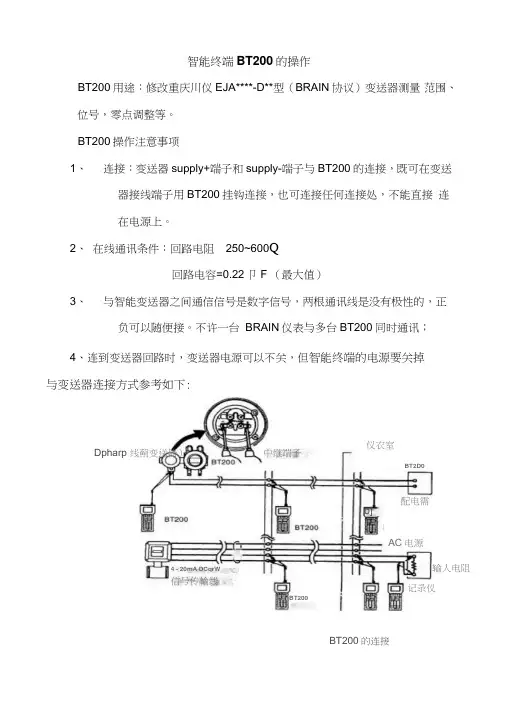
智能终端BT200的操作BT200用途:修改重庆川仪EJA****-D**型(BRAIN 协议)变送器测量 范围、位号,零点调整等。
BT200操作注意事项1、 连接:变送器supply+端子和supply-端子与BT200的连接,既可在变送器接线端子用BT200挂钩连接,也可连接任何连接处,不能直接 连在电源上。
2、 在线通讯条件:回路电阻 250~600Q回路电容=0.22卩F (最大值)3、 与智能变送器之间通信信号是数字信号,两根通讯线是没有极性的,正负可以随便接。
不许一台 BRAIN 仪表与多台BT200同时通讯;4、连到变送器回路时,变送器电源可以不关,但智能终端的电源要关掉与变送器连接方式参考如下:Dpharp 线薊变送器)BT200BT200的连接中继端子仪衣室o]配电需4 - 20mA DCqrW信号传輸线AC 电源记录仪输人电阻 BT2D0注:若按上图通讯不上,考虑回路串接250~600Q电阻,然后变送器supply+端子和supply-端子与BT200的连接。
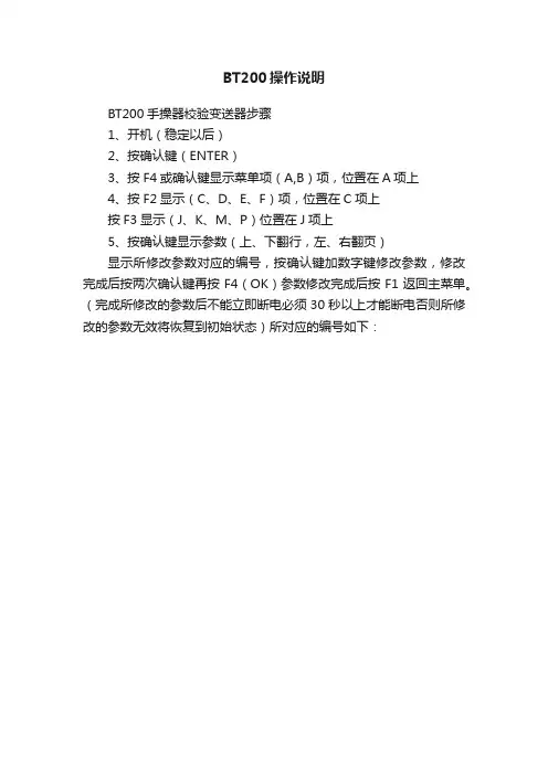
BT200也可夹在电阻两端通讯BT200接在"SUPPLY"的+ .-端F上(使用针钩)智能终端差压变送器接线端手CC24V电源三、BT200的校表过程:(以差压变送器EJA110A-DLS5A-92DA为例)关闭变送器引压管截止阀-开平衡阀-关高压侧截止阀-关低压侧截止阀- 打开变送器2个排气螺钉-BT200与变送器通讯连接(参见上图) -进行位号设置,零点标定,测量范围等操作(修改后需保持30s以上)-完成后将变送器按停用相反顺序逐步投用。
四.BT200基本操作操作a:输入数字:直接按数字/字母键输入按键操作1」-9 M1 N Y SPACE Z W- X I E 9Fb:输入字母(A—Z ):选按下shift键,再同时按数字/字母键,则输入数字/字母键上与shift键边侧位置相对应的字母•注意在按数字/字母键前必须先按下shift键。

Physical Bus Test Device for PROFIBUS-DPBT 200 03/99 EnglishBT 200Physical Bus Test Devicefor PROFIBUS-DPTable of Contents1 DESCRIPTION (2)2 COMMISSIONING (3)3 NORMAL MODE (4)3.1 W IRING T EST (5)3.2 E RROR M ESSAGES OF THE W IRING T EST (6)4 SPECIALIST MODE (8)4.1 O PERATOR C ONTROL (8)4.2 S TATION (RS 485) T EST (10)4.3 B RANCH T EST (11)4.4 D ISTANCE (12)4.5 R EFLECTION T EST (13)4.6 S ERVICE (14)5 MAINTENANCE AND TROUBLE-SHOOTING (15)5.1 C HARGING S TATUS OF THE B ATTERY (15)5.2 C HANGING THE B ATTERY (15)5.3 S ELF-T ESTS (16)5.4 E RROR C ORRECTION T ABLE (17)6 ACCESSORIES AND REPLACEMENT PARTS (18)7 TECHNICAL DATA (19)(S)J31069-D0075-U001-A1-7618 Page 1English 03/99 BT 200 (S)J31069-D0075-U001-A1-7618Page 21 DescriptionPurpose of the BT 200The BT 200 offers diagnostics for PROFIBUS-DP systems without having to use additional measuring aids (e.g., PC or oscilloscope).Operator control elements and displayFig. 1BT 200 operator control elements and display1)PROFIBUS-DP connection (9-pin sub D)2)LC display (2 x 16 characters)3)ON/OFF button 4)TEST key (start test)5)CURSOR keys 6)OK key (various functions)7)ESCAPE key (terminate)8) Charging contactsBT 200 03/99 English (S)J31069-D0075-U001-A1-7618 Page 32 CommissioningBefore initial commissioning, check your de-livery, and charge the battery.Scope of deliveryThe delivery includes:- 1 BT 200- 1 battery- 1 test plug connector (wiring test)- 1 test cable, length: 2 m- 1 user's guideCharging the battery- Open the battery compartment (seechapter on changing the battery), andcheck to detemine whether the battery isinstalled. Install the battery if necessary.- Charge battery of the BT 200 via char-ging shell (approx. 4 hours).U Attention!The battery is always delivered uncharged.The charging shell is not included and must be ordered separately.- Remove the BT 200 from the chargingshell. The device is ready for operation.English 03/99 BT 200 (S)J31069-D0075-U001-A1-7618Page 43 Normal ModeThe BT 200 is turned on with the ON/OFFbutton.Keep the ON/OFF button pressed until you see a reaction on the display.Standby displayThe following display appears for approx. 3seconds after the device is turned on.Battery displayThe battery capacity display is then shown forapprox. 3 seconds.Operational displayAfter the battery display disappears, the BT 200 assumes normal mode and displays thestart screen for the wiring test.Only the wiring test can be performed in nor-mal mode.Energy saver modeIf no keys are pressed for approx. 3 minutes and no measurements are being performed,the BT 200 goes off automatically.BT 200 03/99 English 3.1 Wiring TestPrinciple of measuringThe wiring test for a bus segment is per-formed between the BT 200 and the test plugconnector. During the initialization phase, atest can be performed from connector to con-nector. See figure 2. The test connector isalways installed on the one end of the bussegment.Short circuits can also be determined outsidethe test path. The bus segment may only beequipped with a terminating resistor at thebeginning and at the end.Fig. 2 Step-by-step measuring principlePerforming the testNo stations may be connected to the bus line.The test is started by pressing the TEST key.One of the following two messages is dis-played if the test was concluded successfully.For one terminating resistor (as long as in-stallation has not been completed, only oneterminal resistor is present)After installation has been concluded, two re-sistors must be inserted.The test is concluded by pressing the OK key,and a new wiring test can be started.The wiring test can also be concluded or ter-minated at any time by pressing the ESC key. (S)J31069-D0075-U001-A1-7618 Page 5English 03/99 BT 200(S)J31069-D0075-U001-A1-7618Page 63.2 Error Messages of the Wiring TestStation testCheck to determine whether all plug connec-tors have been disconnected from the sta-tions.Wire mix-upExchange the cores in the corresponding plug connector.U The wiring test must be performed eachtime a new PROFIBUS plug connector isconnected. Otherwise an even numberof wire mix-ups will not be recognized.Short circuitLocate and correct the short circuit.A frequent cause (e.g., of shield short circuits)is the incorrect application of shield braiding in the plug connectors.BT 200 03/99 English Line or shield breakIf several cores or at least one core and theshield are broken or not connected, the BT200 cannot identify the interruption unambi-guously.To obtain a correct measuring result for shieldbreak, the shield may not be connected withground.With all four messages, first check the plugconnectors in question. If these are okay, re-place the cable.None or more than two terminating resistors Page with the "→""←" keys.Place a terminating resistor at the beginningand end of the bus segment.Page with the "→""←" keys.Remove or deactivate all terminating resistorsexcept the two at the beginning and end ofthe bus segment.(S)J31069-D0075-U001-A1-7618 Page 7English 03/99 BT 200 (S)J31069-D0075-U001-A1-7618Page 84 Specialist ModeYou can switch from normal mode to special-ist mode by pressing ESC and OK at thesame time.The following functions are available in spe-cialist mode.- Wiring test. See normal mode.- Station test- Wire mix-up- Short circuit- Line or shield break- None or more than two- Station test (RS 485 test)- Branch test- Distance measurement- Reflection test- Service menu4.1 Operator ControlThe BT 200 is menu-controlled via the input keys of the sealed keyboard (figure 1).CursorThe current cursor position in the display is shown as a flashing arrow and indicates the function which is being performed.BT 200 03/99 EnglishMenu itemsMenu items are selected with the cursor andactivated with the OK key. The ESC key canbe used to terminate a running function or tojump back to the higher-level menu item. Menu structure(S)J31069-D0075-U001-A1-7618 Page 94.2 Station (RS 485) TestThis test is used to test the RS 485 interfaceof a single slave.Performing the testDisconnect bus connector from the slave.Establish point-to-point connection betweenslave and BT 200. See figure 4.U Only the included test cable may be used for this connection.Fig. 4 Point-to-point connectionTurn on the slave since the test must be per-formed with an active slave.Start station test.Set address of the slave to be tested asshown below."←" "→" Change cursor position."↑" "↓" Increment/decrement number.Accept the set three-position number with OK,and start test.Test resultsPossible test results are listed below.- RS 485 okay (slave okay)- RS 485 defective. (No continuous signal receipt; repeat test.)- No response. (Nothing received; wrong slave address may have been set.)- 5V : (corresponding measured value)- RTS signal (YES or NO)4.3 Branch TestThis can be used to check the availability ofall slaves on PROFIBUS or to address an in-dividual slave.The branch test can also be performed be-yond repeaters/LWL.Performing the testDisconnect all masters from the bus (e.g., PG,OP and CP). See figure 5.Connect BT 200 to the bus.Set the baud rate configured on the bus onthe BT 200.Set the desired address for individual slavetest.Set address to "000" for the total test.Start test.Fig. 5 Measuring principle of the branch testTest resultsDuring the total branch test, each availableslave is indicated in a list of available stations(i.e., LIFE LIST).- LIFE LISTFor an individual test- No response. (e.g., No station with thisbus address on the bus.)- Faulty station. (e.g., a slave number has been assigned twice.)4.4 DistanceThe distance can be measured to determinethe length of the PROFIBUS cable.Performing the testDisconnect all bus stations from the bus.Connect test plug connector to one end of theline and the BT 200 to the other end. (Re-move termination for BT 200.)Start distance measurement.After the start, the BT 200 requests three val-ues which must be entered on the keyboard.- Loop resistance (default = 110 Ω/km)The default value can be changed viamenu item Service.- Number of plug connectors with longitu-dinal inductivity (12 Mbaud connector) - Resistance value per connector(default = 0.32 Ω)After entry of the last value and confirmationwith OK, measurement is performed. Measurement resultsThe following appears on the display.The following error messages can occur dur-ing measurement.- No resistor inserted.- Display "0 m" (no plausible length deter-mined)- More than 1 resistor inserted.Possible causes of errors:-Distance < 15 m-Stub lines, located on the measuring pathCorrect the error, and repeat the measure-ment.4.5 Reflection TestThe reflection test can be used to determinefaults (e.g., short circuits and interruptions) orto confirm the distance measurement.Reflexions can occur in the following situa-tions:-Stub lines exist.-Too many terminating resistors havebeen inserted, or none have been in-serted.-Change to a wrong type of cable occurs within the measuring path.-Cable installation is not correct (e.g.,luster terminal connection and so on).Performing the testDisconnect master from the bus, and makesure that no bus communication occurs.Connect BT 200 to one end of the line.Start reflection measurement.Test resultsIf no reflection (i.e., fault) is detected, the fol-lowing message appears.If a reflection is detected, the following mes-sage appears.The number in the display specifies the dis-tance in meters from the measuring point tothe faulty point.If the distance of the reflection measurementcorresponds to a previous distance meas-urement, this distance measurement is con-firmed. The wiring of the bus segment whichwas measured is correct.4.6 ServiceSettingsThe following settings can be changed in theService menu.-Language (German/English)-Loop resistance (50 to 200 Ω/km)-Baud rate (9600 baud to 12 Mbaud)-Contrast (↑↓)Default valuesIf you want to reset all values to their statuson delivery, keep both cursor keys pressedfor approx. three seconds after turning on thedevice.DisplaysThe Service menu gives you the following in-formation.-Firmware version-Battery capacityHardware testThis tests the internal hardware.CalibrationCalibration is not necessary when the stan-dard type-A PROFIBUS cable is used.The accuracy of distance and reflectionmeasurement is achieved by calibration with 2test cables of different known lengths.Fig. 6 Principle of calibration5 Maintenance and Trouble-Shooting5.1 Charging Status of the BatteryThe charging status of the battery is indicatedfor approximately 3 seconds during startup.This display then disappears.The charging status can also be indicated viathe service menu during operation.I f the battery goes dead during operation, thecharging status begins to flash.5.2 Changing the BatteryU Attention! When changing the battery (2), make absolutely sure that the battery con-nector (1) with the red cable (light-colored ca-ble) is inserted to the right.Fig. 7 Changing the battery5.3 Self-TestsT he BT 200 performs self-tests automaticallyand on request (hardware test).- Internal RS 485 driver testThe test is performed each time the sta-tion and branch test is called.- RAM testA cyclic RAM test is performed.- Flash EPROM testA cyclic EPROM test is performed.- RS 485 driver testThe individual tests (e.g., RAM test, flashEPROM test and display key test) can also beselected from specialist mode via the HW testservice menu.If an error is detected during the self-test, youmust proceed as shown in the error correc-tion table.5.4 Error Correction TableFault during startupDisplay Fault Reason Effect Correc-tionNone No dis-play afterswitch-on BatterydeadHard-waredoes notstart up.Chargebatteryor in-stallnewbattery.If possi-ble: "internal error" message Afterswitch-on, "in-ternalerror"messageappears.RAM/EPROMerrordiplay/keyboarddefectiveNo meas-uringpossibleRe-placeBT 200.Fault during operationDisplay Fault Reason Effect Correc-tionBattery display flashes before.Devicegoes off.Battery isdead.No meas-uringpossibleChargebattery/installnewone.None Devicegoes off.Time withno useractivitywas ex-ceeded.None PressONbutton.Internal driver defect Internaldriver isdefective.HW de-fectNo sta-tion/branch testpossibleRe-placeBT 200.6 Accessories and Replacement PartsThe following components can be ordered under their MLFB number.Designation/Picture MLFB NumberTest connector 6EP8106-0AC20Charging shell w. power pack for:230 V AC110 V AC 6GT2003-1AA00 6EP8106-0HB01Battery with connectioncable6EP8106-HA01Test cable9-pin sub D on9-pin sub D (1 to 1)6EP8106-OHC017 Technical DataGeneralDimensions210 * 100 * 55 mm²Weight400 gBattery capacity≥ 720 mAhLife≥ 8 hVoltage supply NiCd, 4.8 V battery Display LCD, 2 * 16 charac-tersBaud rate9600 Bd to 12 MBd Protection class IP 30Measuring accuracy Length measurement(+/-3m) Environmental RequirementsOperating temperature+ 5°C to +45°C Storage temperature-20°C to +60°C Relative humidity Maximal 95% / 24°CMiddle 75% / 17°C(withoutcondensation)Air pressureoperation storage 795 to 1080 hPa 660 to 1080 hPaEMC guidelinesCE labelling DIN EN 61326-1:1998EN 50 081-1EN 50 082-2 Physical RequirementsVibration during operation IEC 1131-2Shock stress during operation IEC 1131-2Free fall IEC 1131-2/68-2-32English 03/99 BT 200 (S)J31069-D0075-U001-A1-7618Page 20Abbreviations Bd Baud (1 Bd = 1 character (bit/second)BTPhysical bus test device CPCommunications processor EMCElectromagnetic compatibility MBd1 MBd = 106 baud NiCdNickel cadmium NNMiles above sea level OPOperator panel PGProgrammer RTS Request to sendInfo Info Info Info Info Info Info This document can be downloaded free of charge from the Internet under the following URL:http:\\www.ad.siemens.de\simatic-csContinuous current information on SIMATIC products is available on the Internet under:http:\\www.ad.siemens.de\simaticSIMATIC Customer Support can be reached under:Tel. +49 (911) 895 7000Fax. +49 (911) 895 7002Siemens AGBereich Automatisierungs- und Antriebstecnik Geschäftsgebiet KombinationstechnikA&D SEPostfach 2355, D-90713 Fürth©Siemens AG 1999Subject to change without prior noticeSiemens AktiengesellschaftOrder-no.: (S)J13069-D0075-U001-A1-7618Printed in the Federal Republic of Germany。

BT200使用手册——用于PROFIBUS-DP的总线测试诊断工具1 概述BT200的使用功能它可以提供用于PROFIBUS-DP系统的诊断而不需要再使用额外的测量器件(如,PC 或示波器)BT200-版本2BT200的第二个版本可以提供如下的附加功能:●登录操作●6种可选用户语言●DP主站接口测试●主站地址显示●从站接口测试●新型廉价紧凑型充电装置操作控制面板及显示1)DP接口2)LC显示3) 开/关键4)线充电接口5)测试键(开始测试)6)方向键7) Ok键(各种功能)8)取消键(终止)9)座充电接口2 设定在初始化设定之前,要检查并更换电池。
打开电池端盖,检查电池是否已经装好,如果需要的话安装好电池。
在更换电池期间,不能进行测试。
3 常规模式BT200由开关键打开。
保持其按下直到在屏幕上出现反应为止。
标准显示在开机后将显示下面图画然后显示电池情况电池状况显示过后,BT200默认进入常规模式并显示用于写测试的开机屏幕在常规模式下只能进行写测试。
当在登录模式下(指针看起来是不一样的),在每次测试之后会再出现如下画面电能节省模式如果3分钟内没有进行任何操作,那么BT200将会自动关闭3.1 写测试测量原则总线段的写测试在BT200与测试连接器之间进行。
在安装阶段,可以在连接器之间进行一个测试,如下图所示,测试连接器通常安装在总线段的另一端。
在测试路径之外也会造成短路。
总线段必须要在两端设置终端电阻。
进行测试可以在连接站点或断开的情况下进行测试。
在按下测试键之后,测试就开始了。
如果测试成功的话,将会显示下述两幅画面之一。
只有一个终端电阻(只要安装没有完成,只会显示一个终端电阻)当安装完成之后,会出现两个终端电阻。
按下OK键,测试即结束。
接下来也可以进行新的测试。
测试也可以在按下ESC键之后被终止。
3.2 写测试的错误信息站测试检测是否将所有站点以及电能部件的能量已经断掉。
线混合在相应的连接插头之间交换电缆线芯短路定位并纠正短路故障。