外文文献及翻译_可编程逻辑控制器
- 格式:docx
- 大小:24.58 KB
- 文档页数:14
英语原文:Programmable logic con trollerA programmable logic controller (PLC) or simply programmable controller is a digital computer used for automatio n of in dustrial processes, such as con trol of machi nery on factory assembly lin es. Un like gen eral-purpose computers, the PLC is desig ned for multiple in puts and output arrangements,extended temperature ranges, immunity to electrical noise, and resista nee to vibratio n and impact. Programs to con trol mach ine operati on are typically stored in battery-backed or non-volatile memory・ A PLC is an example of a real time system since output results must be produced in resp onse to in put con diti ons with in a boun ded time, otherwise uninten ded operatio n will result..FeaturesThe main differe nee from other computers is that PLC are armored for severe con diti on (dust, moisture, heat, cold, etc) and have the facility for extensive input/output (I/O) arrangements.These connect the PLC to sensors and actuators. PLC read limit switches, analog process variables (such as temperature and pressure),a nd the positions of complex positi oning systems・ Some eve n use mach ine visio n. On the actuator side, PLC operate electric motors, pn eumatic or hydraulic cyli nders, magn etic relays or sole no ids, or an alog outputs. The in put/output arran geme nts may be built into a simple PLC, or the PLC may have external I/O modules attached to a computer network that plugs into the PLC・PLC were inven ted as replaceme nts for automated systems that would use hun dreds or thousands of relays, cam timers, and drum sequencers. Often, a single PLC can be programmed to replace thousa nds of relays. Programmable con trailers were in itially adopted by the automotive manu facturi ng in dustry, where software revisio n replaced the re-wiri ng of hard-wired con trol pan els whe n producti on models cha nged.Many of the earliest PLC expressedall decision making logic in simple ladder logic whichappeared similar to electrical schematic diagrams. The electricia ns were quite able to trace out circuit problems with schematic diagrams using ladder logic. This program no tati on was chose n to reduce training dema nds for the existi ng tech nicians. Other early PLC used a form of in structi on list program ming, based on a stack-based logic solver.The functionality of the PLC has evolved over the years to include sequential relay con trol, moti on con trol, process con trol, distributed con trol systems and n etwork ing. The data han dli ng, storage, process ing power and com muni cati on capabilities of some moder n PLC are approximately equivale nt to desktop computers. PLC-like program ming comb ined with remote I/O hardware, allow a general-purpose desktop computer to overlap some PLC in certa in applicati ons.PLC compared with other con trol systemsPLC are well-adapted to a range of automati on tasks. These are typically in dustrial processes in manu facturi ng where the cost of develop ing and maintaining the automati on system is high relative to the total cost of the automation, and where changes to the system would be expected duri ng its operatio nal life. PLC contain in put and output devices compatible with in dustrial pilot devices and con trols; little electrical desig n is required, and the desig n problem cen ters on express ing the desired seque nee of operati ons in ladder logic no tati on. PLC applicati ons are typically highly customized systems so the cost of a packaged PLC is low compared to the cost of a specific custom-built controller design. On the other hand, in the case of mass-produced goods, customized con trol systems are econo mic due to the lower cost of the comp onen ts, which can be optimally chose n in stead of a ”ge neric" solution, and where the non・recurring engineering charges are spread over thousands of places.For high volume or very simple fixed automati on tasks, differe nt tech niq ues are used. For example, a con sumer dishwasher would be con trolled by an electromecha ni cal cam timer costing only a few dollars in production quantities.A microcontroller-based design would be appropriate where hundreds or thousandsof units willbe produced and so the development cost (design of power supplies and input/outputhardware) can be spread over many sales, and where the end-user would not n eed to alter the con trol. Automotive applicati ons are an example; millio ns of un its are built each year, and very few en d-users alter the program ming of these con trailers. However, some specialty vehicles such as tran sit busses econo mically use PLC in stead of custom-desig ned con trols, because the volumes are low and the developme nt cost would be unecono mic.Very complex process control, such as used in the chemical industry, may require algorithms and performs nee beyond the capability of eve n high-performa nee PLC. Very high - speed or precisi on con trols may also require customized solutio ns; for example, aircraft flight con trols.PLC may in elude logic for sin gle-variable feedback an alog con trol loop, a "proporti on al, in tegral, derivative" or ”PID con troller." A PID loop could be used to con trol the temperature of a manu facturi ng process, for example. Historically PLC were usually con figured with only a few analog control loops; where processesrequired hundreds or thousands of loops, a distributed con trol system (DCS) would in stead be used. However, as PLC have become more powerful, the boundary between DCS and PLC applications has become less clear-cut.Digital and an alog sig nalsDigital or discrete signals behave as binary switches, yielding simply an On or Off sig nal (1 or 0, True or False, respectively). Push butt on s, limit switches, and photoelectric sen sors are examples of devices providi ng a discrete sig nal. Discrete sig nals are sent using either voltage or current, where a specific range is designated asOn and another asOff. For example, a PLC might use 24 V DC I/O, with values above 22 V DC represe ntingOn, values below 2VDC represe nti ng Off, and in termediate values un defi ned. In itially, PLC had only discrete I/O.Analog signals are like volume controls, with a range of values between zero and full・ scale. These are typically in terpreted as in teger values (co un ts) by the PLC, with various ranges of accuracy depending on the device and the number of bits available to store the data. As PLC typicallyuse 16-bit sig ned binary processors, the in teger values are limited betwee n - 32,768 and +32,767. Pressure, temperature, flow, and weight are often represented by analog signals. Analog signals can use voltage or current with a magnitude proportional to the value of the process sig nal. For example, an an alog 4-20 m or 0 ・ 10 V in put would be conv erted into an in teger value of 0-32767.Curre nt in puts are less sen sitive to electrical no ise (i.e.from welders or electric motor starts) tha n voltage in puts.System scaleA small PLC will have a fixed nu mber of conn ecti ons built in for in puts and outputs. Typically, expa nsions are available if the base model does not have eno ugh I/O.Modular PLC have a chassis (also called a rack) into which is placed modules with differe nt functions. The processor and selecti on of I/O modules is custom for the particular application. Several racks can be administered by a single processor, and may have thousands of in puts and outputs・ A special high speed serial I/O link is used so that racks can be distributed away from the processor, reduc ing the wiri ng costs for large pla nts.PLC used in larger I/O systems may have peer-to-peer (P2P) com muni cati on betwee n processors. This allows separate parts of a complex process to have in dividual con trol while allowi ng the subsystems to co-ord in ate over the com muni cati on link. These com muni cati on links are also ofte n used for HMI (Huma Machi ne In terface) devices such as keypads or PC-type workstati ons. Some of today's PLC can com muni cate over a wide range of media in cludi ng RS-485, Coaxial, and eve n Ether net for I/O con trol at n etwork speeds up to 100m・Programmi ngEarly PLC, up to the mid・ 1980s, were programmed using proprietary programming pan els or special-purpose program ming term in als, which ofte n had dedicated fun cti on keys represe nting the various logical eleme nts of PLC programs. Programs were stored on cassette tape cartridges.Facilities for printing and documentation were very minimal due to lack of memory capacity. More rece ntly, PLC programs are typically writte n in a special applicati on on a pers onal computer, the n dow nl oaded by a direct-c onnection cable or over a n etwork to the PLC.The very oldest PLC used non-v olatile mag netic core memory but now the program is stored in the PLC either in battery-backed-up RAM or some other non-volatile flash memory.Early PLC were desig ned to replace relay logic systems. These PLC were programmed in "ladder logic**, which stron gly resembles a schematic diagram of relay logic. Moder n PLC can be programmed in a variety of ways, from ladder logic to more traditional programming languages such as BASIC and C. Another method is State Logic, a Very High Level Program ming Lan guage desig ned to program PLC based on State Tran siti on Diagrams.Recently, the International standard IEC 61131-3 has become popular. IEC 61131-3 currently defines five programming languages for programmable control systems: FBD (Function block diagram), LD (Ladder diagram), ST (Structured text, similar to the Pascal programming language), IL (Instruction list, similar to assembly Ianguage) and SFC (Seque ntial fun cti on chart). These tech niq ues emphasize logical orga ni zatio n of operati ons.While the fun dame ntal con cepts of PLC program ming are com mon to all manu facturers, differences in I/O addressing, memory organization and instruction sets mean that PLC programs are never perfectly interchangeable between different makers. Even within the same product line of a single manufacturer, different models may not be directly compatible.User in terfacePLC may n eed to in teract with people for the purpose of con figurati on, alarm report ing or everyday con trol. A Huma n-Mach ine In terface (HMI) is employed for this purpose. HMI' are also referred to as MMT (Ma n Mach ine In terface) and GUI (Graphical User In terface).A simple system may use butt ons and lights to in teract with the user. Text displays are available as well as graphical touch scree ns. Most moder n PLC can com muni cate over a n etwork to some other system, such as a computer running a SCADA (Supervisory Con trol And Data Acquisiti on) system or web browser.Com mun icatio nsPLC usually have built in com muni cati ons ports usually 9・Pi n RS232, and opti on ally for RS485 and Ether net. DF1 is usually in eluded as one of the com muni cati ons protocols. Other com muni cati ons protocols that may be used are listed in the List of automati on protocols.HistoryThe PLC was inven ted in resp onse to the n eeds of the America n automotive in dustry. Before the PLC, con trol, seque ncing, and safety in terlock logic for manu facturi ng automobiles was accomplished using relays, timers and dedicated closed-loop con trailers. The process for updati ng such facilities for the yearly model cha nge-over was very time consuming and expe nsive, as the relay systems n eeded to be rewired by skilled electricia ns. In 1968 GM Hydra (the automatic transmission division of General Motors) issued a request for proposal for an electro nic replaceme nt for hard-wired relay systems.The wi nning proposal came from Bedford Associates of Bedford, Massachusetts. The first PLC, desig nated the 084 because it was Bedford Associates' eighty-fourth project, was the result・Bedford Associates started a new compa ny dedicated to develop ing, manu facturi ng, selli ng, and servic ing this new product: Mod, which stood for One of the people whoworked on that project was Dick Morley, who is considered to be the "father" of the PLC. The brand was sold in 1977 to Gould Electr oni cs, and later acquired by Germa n Compa ny AEG and then by French Schn eider Electric, the curre nt owner.One of the very first 084 models built is now on display at headquarters in North Andover, Massachusetts .It was presented to by GM, when the unit was retired after nearly twenty years of unin terrupted service.The automotive industry is still one of the largest users of PLC, and still numbers some of its controller models such that they end with eighty-four. PLC are used in many different in dustries and machi nes such as packag ing and semic on ductor mach in es. Well known PLC brands are Toshiba, Sieme ns, Alle Bradley, ABB, Mitsubishi, Omro n, and Gen eral Electri・附录B英语翻译:可编程序控制器可编程逻辑控制器(PLC或干脆可编程序控制器是一个数字化的计算机用于自动化的工业生产过程,如控制机械的工厂装配生产线。
电气系统可编程序控制器中英文资料外文翻译文献英文原文Programmable controller designed for electro-pneumatic systems This project deals with the study of electro-pneumatic systems and theprogrammable controller that provides an effective and easy way to control thesequence of the pneumatic actuators movement and the states of pneumatic system.The project of a specific controller for pneumatic applications join the studyof automation design and the control processing of pneumatic systems with theelectronic design based on microcontrollers to implement the resources of thecontroller.1.IntroductionThe automation systems that use electro-pneumatic technology are formed mainlyby three kinds of elements: actuators or motors, sensors or buttons and controlelements like valves. Nowadays, most of the control elements used to execute thelogic of the system were substituted by the Programmable LogicController(PLC).Sensors and switches are plugged as inputs and the direct controlvalves for the actuators are plugged as outputs. An internal program executes allthe logic necessary to the sequence of the movements, simulates other componentslike counter, timer and control the status of the system.With the use of the PLC the project wins agility, because it is possible tocreate and simulate the system as many times as needed. Therefore, time can besaved, risk of mistakes reduced and complexity can be increased using the sameelements.A conventional PLC, that is possible to find on the market from many companies,offers many resources to control not only pneumatic systems, but all kinds of systemthat uses electrical components. The PLC can be very versatile and robust to beapplied in many kinds of application in the industry or even security system andautomation of buildings.Because of those characteristics, in some applications the PLC offers to much resources that are not even used to control the system, electro-pneumatic system is one of this kind of application. The use of PLC, especially for small size systems, can be very expensive for the automation project.An alternative in this case is to create a specific controller that can offer the exactly size and resources that the project needs[3,4].This can be made using microcontrollers as the base of this controller.The controller, based on microcontroller, can be very specific and adapted to only one kind of machine or it can work as a generic controller that can be programmed as a usual PLC and work with logic that can be changed. All these characteristics depend on what is needed and how much experience the designer has with developing an electronic circuit and firmware for microcontroller. But the main advantage of design the controller with the microcontroller is that the designer has the total knowledge of his controller, which makes it possible to control the size of the controller, change the complexity and the application of it. It means that the project gets more independence from other companies, but at the same time the responsibility of the control of the system stays at the designer hands2.Electro-pneumatic systemOn automation system one can find three basic components mentioned before ,plus a logic circuit that controls the system. An adequate technique is needed to project the logic circuit and integrate all the necessary components to execute the sequence of movements properly.For a simple direct sequence of movement an intuitive method can be used[1,5],but for indirect or more complex sequences the intuition can generate a very complicated circuit and signal mistakes. It is necessary to use another method that can save time of the project, make a clean circuit, can eliminate occasional signal overlapping and redundant circuits.The presented method is called step-by-step or algorithmic [1,5], it is valid for pneumatic and electro-pneumatic systems and it was used as a base in this work. The method consists of designing the systems based on standard circuits made for each change on the state of the actuators, these changes are called steps.Fig.1.Standard circuit for the pneumatic system.Fig.2.Standard circuit for the electro-pneumatic system.The first part is to design those kinds of standard circuits for each step, the next task is to link the standard circuits and the last part to connect the control element that receive signals from sensors, switches and the previous movement and give the air or electricity to the supply lines of each step. In Figs.1 and 2 the standard circuits are drawn for pneumatic and electro-pneumatic system [8].It is possible to see the relations with the previous and the next steps.3. The method applied inside the controllerThe result of the method presented before is a sequence of movements of the actuator that is well defined by steps. It means that each change on the position of the actuators is a new state of the system and the transition between statesis called step.The standard circuit described before helps the designer to define the states of the systems and to define the condition to each change between the states. In the end of the design, the system is defined by a sequence that never chances and states that have the inputs and the outputs well defined. The inputs are the condition for the transition and the outputs are the result of the transition.All the configuration of those steps stays inside of the microcontroller and is executed the same way it was designed. The sequences of strings are programmed inside the controller with 5 bytes; each string has the configuration of one step of the process. There are two bytes for the inputs, one byte for the outputs and two more for the other configurations and auxiliary functions of the step. After programming, this sequence of strings is saved inside of a non-volatile memory of the microcontroller, so they can be read and executed.The controller task is not to work in the same way as a conventional PLC, but the purpose of it is to be an example of a versatile controller that is design for an specific area. A conventional PLC process the control of the system using a cycle where it makes an image of the inputs, execute all the conditions defined by the configuration programmed inside, and then update the state of the outputs. This controller works in a different way, where it read the configuration of the step, wait the condition of inputs to be satisfied, then update the state or the outputs and after that jump to the next step and start the process again.It can generate some limitations, as the fact that this controller cannot execute, inside the program, movements that must be repeated for some time, but this problem can be solved with some external logic components. Another limitation is that the controller cannot be applied on systems that have no sequence. These limitations are a characteristic of the system that must be analyzed for each application.4. Characteristics of the controllerThe controller is based on the MICROCHIP microcontroller PIC16F877 [6,7] with 40 pins, and it has all the resources needed for this project. It ha enough pins for all the components, serial communication implemented in circuit, EEPROM memory to save all the configuration of the system and the sequence of steps. For the execution of the main program, it offers complete resources as timers and interruptions.The list of resources of the controller was created to explore all the capacity of the microcontroller to make it as complete as possible. During the step, the program chooses how to use the resources reading the configuration string of the step. This string has two bytes for digital inputs, one used as a mask and the other one used as a value expected. One byte is used to configure the outputs value. One bytes more is used for the internal timer, the analog input or time-out. The EEPROM memory inside is 256 bytes length that is enough to save the string of the steps, with this characteristic it is possible to save between 48 steps.The controller has also a display and some buttons that are used with an interactive menu to program the sequence of steps and other configurations.4.1.Interaction componentsFor the real application the controller must have some elements to interact with the final user and to offer a complete monitoring of the system resources that are available to the designer while creating the logic control of the pneumatic system:.Interactive mode of work; function available on the main program for didactic purposes, the user gives the signal to execute the step..LCD display, which shows the status of the system, values of inputs, outputs, timer and statistics of the sequence execution..Beep to give important alerts, stop, start and emergency..Leds to show power on and others to show the state of inputs and outputs.4.2. SecurityTo make the final application works property, a correct configuration to execute the steps in the right way is needed, but more then that it must offer solutions in case of bad functioning or problems in the execution of the sequence. The controller offers the possibility to configure two internal virtual circuits that work in parallel to the principal. These two circuits can be used as emergency or reset buttons and can return the system to a certain state at any time[2]. There are two inputs that work with interruption to get an immediate access to these functions. It is possible to configure the position, the buttons and the value of time-out of the system.er interfaceThe sequence of strings can be programmed using the interface elements of the controller. A computer interface can also be used to generate the user program easily. With a good documentation the final user can use the interface to configure the strings of bytes that define the steps of the sequence. But it is possible to create a program with visual resources that works as a translator to the user,it changes his work to the values that the controller understands.To implement the communication between the computer interface and the controller a simple protocol with check sum and number of bytes is the minimum requirements to guarantee the integrity of the data.4.4. FirmwareThe main loop works by reading the strings of the steps from the EEPROM memory that has all the information about the steps.In each step, the status of the system is saved on the memory and it is shown on the display too. Depending of the user configuration, it can use the interruption to work with the emergency circuit or time-out to keep the system safety.A block diagram of micro controller main program is presented.5.Example of electro-pneumatic systemThe system is not a representation of a specific machine, but it is made with some common movements and components found in a real one. The system is composed of four actuators. The actuators A,B and C are double acting and D-single acting. Actuator A advances and stays in specified position till the end of the cycle, it could work fixing an object to the next action for example(Fig.3), it is the first step. When A reaches the end position, actuator C starts his work together with B, making as many cycles as possible during the advancing of B. It depends on how fast actuator B is advancing; the speed is regulated by a flowing control valve. It was the second step. B and C are examples of actuators working together, while B pushes an object slowly, C repeats. its work for some time.Fig.3.Time diagram of A,B,C and D actuators.When B reaches the final position, C stops immediately its cycle and comes back to the initial position. The actuator D is a single acting one with spring return and works together with the back of C, it is the third step. D works making very fast forward and backward movement, just one time. Its backward movement is the fourth step. D could be a tool to make a hole on the object.When D reaches the initial position, A and B return too, it is the fifth step.Fig.4 shows the first part of the designing process where all the movements of each step should be defined[2]. (A+)means that the actuator A moves to the advanced position and (A . )to the initial position. The movements that happen at the same time are joined together in the same step. The system has five steps.Fig.4.Step sequence of A,B,C and D actuators.These two representations of the system(Figs.3 and 4) together are enough to describe correctly all the sequence. With them is possible to design the whole control circuit with the necessary logic components. But till this time, it is not a complete system, because it is missing some auxiliary elements that are not included in this draws because they work in parallel with the main sequence.These auxiliary elements give more function to the circuit and are very important to the final application; the most important of them is the parallel circuit linked with all the others steps. That circuit should be able to stop the sequence at any time and change the state of the actuators to a specific position. This kind of circuit can be used as a reset or emergency buttons.The next Figs.5 and 6 show the result of using the method without the controller. These pictures are the electric diagram of the control circuit of the example, including sensors, buttons and the coils of the electrical valves.Fig.5.Electric diagram of the example.Fig.6.Electric diagram of the example.The auxiliary elements are included, like the automatic/manual switcher that permit a continuous work and the two start buttons that make the operator of a machine use their two hands to start the process, reducing the risk of accidents.6. Changing the example to a user programIn the previous chapter, the electro-pneumatic circuits were presented, used to begin the study of the requires to control a system that work with steps andmust offer all the functional elements to be used in a real application. But, as explained above, using a PLC or this specific controller, the control becomes easier and the complexity can be increase also.It shows a resume of the elements that are necessary to control the presented example.With the time diagram, the step sequence and the elements of the system described in Figs.3 and 4 it is possible to create the configuration of the steps that can be sent to the controller.While using a conventional PLC, the user should pay attention to the logic of the circuit when drawing the electric diagram on the interface (Figs.5and 6), using the programmable controller, describe in this work, the user must know only the concept of the method and program only the configuration of each step.It means that, with a conventional PLC, the user must draw the relation between the lines and the draw makes it hard to differentiate the steps of the sequence. Normally, one needs to execute a simulation on the interface to find mistakes on the logic.The new programming allows that the configuration of the steps be separated, like described by the method. The sequence is defined by itself and the steps are described only by the inputs and outputs for each step.The structure of the configuration follows the order:1-byte: features of the step;2-byte: for the inputs;3-byte: value expected on the inputs;4-byte: value for the outputs;5-byte: value for the extra function.Fig.7.Actuators A and B, and sensors.Fig.8.Actuators C and D, and sensors.Table 5 shows how the user program is saved inside the controller, this is the program that describes the control of the example shown before.The sequence can be defined by 25 bytes. These bytes can be divided in five strings with 5 bytes each that define each step of the sequence (Figs.7 and 8).7. ConclusionThe controller developed for this work shows that it is possible to create a very useful programmable controller based on microcontroller. External memories or external timers were not used in case to explore the resources that the microcontroller offers inside. Outside the microcontroller, there are only components to implement the outputs, inputs, analog input, display for the interface and the serial communication.Using only the internal memory, it is possible to control a pneumatic system that has a sequence with 48 steps if all the resources for all steps are used, but it is possible to reach sixty steps in the case of a simpler system.The programming of the controller does not use PLC languages, but a configuration that is simple and intuitive. With electro-pneumatic system, the programming follows the same technique that was used before to design the system, but here the designer works directly with the states or steps of the system.With a very simple machine language the designer can define all the configuration of the step using four or five bytes. It depends only on his experience to use all the resources of the controller.The controller task is not to work in the same way as a commercial PLC but the purpose of it is to be an example of a versatile controller that is designed for a specific area. Because of that, it is not possible to say which one works better; the system made with microcontroller is an alternative that works in a simple way.References[1]E.Nelli Silva,Fluid-mechanics systems Manual, Escola PolitecnicaUSP,2002(in Portuguese).[2]J.Swider,Control and Automation of Technological Process and Mechatronic systems,Silesian University Publishing Company,Gli-wice,2002(redaction in Polish).[3]J.Swider, G.Wszolek, W.Carvalho. Example of the system prepared to be controlled by the controller based on microcontroller,in:12 International Scientific Conference—Achievements in Mechanical and MaterialsEngineering,Gliwice-Zakopane,Poland,2003,pp.965-970.[4]J.Swider,G.Wszolek,W.Carvalho, Controller based on microcontroller designed to execute the logic control of pneumatic systems, in:12International Scientific Conference— Achievements in Mechanical and Materials Engineering,Gliwice-Zakopane,Poland,2003,pp. 959–964.[5]J.Swider,G.Wszoek, The methodical collection of laboratory and project tasks of technological process control in Pneumatic and Electro-pneumatic Systems with Logical PLC Control, Silesian University Publishing Company,Gliwice,2003.[6]PIC 16f87xDatasheet.MICROCHIP,2001.[7]Application notes AN587 and AN546.MICROCHIP,1997.[8]Fundamental of electro-pneumatic—FESTODidactic,2000.中文翻译应用于电气系统的可编程序控制器摘要此项目主要是研究电气系统以及简单有效的控制气流发动机的程序和气流系统的状态。
毕业设计中英文翻译院系专业班级姓名学号指导教师20**年 4 月Programmable Logic Controllers (PLC)1、MotivationProgrammable Logic Controllers (PLC), a computing device invented by Richard E. Morley in 1968, have been widely used in industry including manufacturing systems, transportation systems, chemical process facilities, and many others. At that time, the PLC replaced the hardwired logic with soft-wired logic or so-called relay ladder logic (RLL), a programming language visually resembling the hardwired logic, and reduced thereby the configuration time from 6 months down to 6 days [Moody and Morley, 1999].Although PC based control has started to come into place, PLC based control will remain the technique to which the majority of industrial applications will adhere due to its higher performance, lower price, and superior reliability in harsh environments. Moreover, according to a study on the PLC market of Frost and Sullivan [1995], an increase of the annual sales volume to 15 million PLCs per year with the hardware value of more than 8 billion US dollars has been predicted, though the prices of computing hardware is steadily dropping. The inventor of the PLC, Richard E Morley, fairly considers the PLC market as a 5-billion industry at the present time.Though PLCs are widely used in industrial practice, the programming of PLC based control systems is still very much relying on trial-and-error. Alike software engineering, PLC software design is facing the software dilemma or crisis in a similar way. Morley himself emphasized this aspect most forcefully by indicating [Moody and Morley, 1999, p. 110]:`If houses were built like software projects, a single woodpecker could destroy civilization.”Particularly, practical problems in PLC programming are to eliminate software bugs and to reduce the maintenance costs of old ladder logic programs. Though the hardware costs of PLCs are dropping continuously, reducing the scan time of the ladder logic is still an issue in industry so that low-cost PLCs can be used.In general, the productivity in generating PLC is far behind compared to other domains, for instance, VLSI design, where efficient computer aided design tools are in practice. Existent software engineering methodologies are not necessarily applicable to the PLC basedsoftware design because PLC-programming requires a simultaneous consideration of hardware and software. The software design becomes, thereby, more and more the major cost driver. In many industrial design projects, more than SO0/a of the manpower allocated for the control system design and installation is scheduled for testing and debugging PLC programs [Rockwell, 1999].In addition, current PLC based control systems are not properly designed to support the growing demand for flexibility and reconfigurability of manufacturing systems. A further problem, impelling the need for a systematic design methodology, is the increasing software complexity in large-scale projects.PLCs (programmable logic controllers) are the control hubs for a wide variety of automated systems and processes. They contain multiple inputs and outputs that use transistors and other circuitry to simulate switches and relays to control equipment. They are programmable via software interfaced via standard computer interfaces and proprietary languages and network options.Programmable logic controllers I/O channel specifications include total number of points, number of inputs and outputs, ability to expand, and maximum number of channels. Number of points is the sum of the inputs and the outputs. PLCs may be specified by any possible combination of these values. Expandable units may be stacked or linked together to increase total control capacity. Maximum number of channels refers to the maximum total number of input and output channels in an expanded system. PLC system specifications to consider include scan time, number of instructions, data memory, and program memory. Scan time is the time required by the PLC to check the states of its inputs and outputs. Instructions are standard operations (such as math functions) available to PLC software. Data memory is the capacity for data storage. Program memory is the capacity for control software.Available inputs for programmable logic controllers include DC, AC, analog, thermocouple, RTD, frequency or pulse, transistor, and interrupt inputs. Outputs for PLCs include DC, AC, relay, analog, frequency or pulse, transistor, and triac. Programming options for PLCs include front panel, hand held, and computer.Programmable logic controllers use a variety of software programming languages for control. These include IEC 61131-3, sequential function chart (SFC), function block diagram (FBD), ladder diagram (LD), structured text (ST), instruction list (IL), relay ladder logic (RLL), flow chart, C, and Basic. The IEC 61131-3 programming environment provides support for five languages specified by the global standard: Sequential Function Chart,Function Block Diagram, Ladder Diagram, Structured Text, and Instruction List. This allows for multi-vendor compatibility and multi-language programming. SFC is a graphical language that provides coordination of program sequences, supporting alternative sequence selections and parallel sequences. FBD uses a broad function library to build complex procedures in a graphical format. Standard math and logic functions may be coordinated with customizable communication and interface functions. LD is a graphic language for discrete control and interlocking logic. It is completely compatible with FBD for discrete function control. ST is a text language used for complex mathematical procedures and calculations less well suited to graphical languages. IL is a low-level language similar to assembly code. It is used in relatively simple logic instructions. Relay Ladder Logic (RLL), or ladder diagrams, is the primary programming language for programmable logic controllers (PLCs). Ladder logic programming is a graphical representation of the program designed to look like relay logic. Flow Chart is a graphical language that describes sequential operations in a controller sequence or application. It is used to build modular, reusable function libraries. C is a high level programming language suited to handle the most complex computation, sequential, and data logging tasks. It is typically developed and debugged on a PC. BASIC is a high level language used to handle mathematical, sequential, data capturing and interface functions.Programmable logic controllers can also be specified with a number of computer interface options, network specifications and features. PLC power options, mounting options and environmental operating conditions are all also important to consider.2、ResumeA PLC (programmable Logic Controller) is a device that was invented to replace the necessary sequential relay circuits for control.The PLC works by looking at its input and depending upon their state, turning on/off its outputs. The user enters a program, usually via software or programmer, which gives the desired results.PLC is used in many "real world" applications. If there is industry present, chance are good that there is a PLC present. If you are involved in machining, packing, material handling, automated assembly or countless other industries, you are probably already using them. If you are not, you are wasting money and time. Almost any application that needs some type of electrical control has a need for a PLC.For example, let's assume that when a switch turns on we want to turn a solenoid on for 5second and then turn it off regardless of how long the switch is on for. We can do this with a simple external timer. But what if the process included 10 switches and solenoids? We should need 10 external times. What if the process also needed to count how many times the switch individually turned on? We need a lot of external counters.As you can see the bigger the process the more of a need we have for a PLC. We can simply program the PLC to count its input and turn the solenoids on for the specified time.We will take a look at what is considered to be the "top 20" PLC instructions. It can be safely estimated that with a firm understanding of these instructions one can solve more than 80% of the applications in existence.Of course we will learn more than just these instruction to help you solve almost ALL potential PLC applications.The PLC mainly consists of a CPU, memory areas, and appropriate circuits to receive input/output data. We can actually consider the PLC to be a box full of hundreds or thousands of separate relay, counters, times and data storage locations,Do these counters,timers, etc. really exist? No,they don't "physically" exist but rather they simulated and be considered software counters, timers, etc. . These internal relays are simulated through bit locations in registers.What does each part do? Let me tell you.Input RelaysThese are connected to the outside world.They physically exsit and receive signals from switches,sensors,ect..Typically they are not relays but rather they are transistors.Internal Utility RelaysThese do not receive signals from the outside world nor do they physically exist.they are simulated relays and are what enables a PLC to eliminate external relays.There are also some special relays that are dedicated to performing only one task.Some are always on while some are always off.Some are on only once during power-on and are typically used for initializing data that was stored.CountersThese again do not physically exist. They are simulated counters and they can be programmed to count pulses.Typically these counters can count up,down or both up anddown.Since they are simulated,they are limited in their counting speed.Some manufacturers also include high-speed counters that are hardware based.We think of these as physically existing.Most times these counters can count up,down or up and down.TimersThese also do not physically exist.They come in many varieties and increments.The most common type is an on-delay type.Others include off-delays and both retentive and non-retentive types.Increments vary from 1ms through 1s.Output RelaysThere are connected to the outside world.They physically exist and send on/off signals to solenoids,lights,etc..They can be transistors,relays,or triacs depending upon the model chosen Data StorageTypically there are registers assigned to simply store data.They are usually used as temporary storage for math or data manipulation.They can also typically be used to store data when power is removed form the PLC.Upon power-up they will still have the same contents as before power was moved.Very convenient and necessary!A PLC works by continually scanning a program.We can think of this scan cycle as consisting of 3 important steps.There are typically more than 3 but we can focus on the important parts and not worry about the others,Typically the others are checking the system and updating the current internal counter and timer values,Step 1 is to check input status,First the PLC takes a look at each input to determine if it is on off.In other words,is the sensor connected to the first input on?How about the third...It records this data into its memory to be used during the next step.Step 2 is to execute program.Next the PLC executes your program one instruction at a time.Maybe your program said that if the first input was on then it should turn on the first output.Since it already knows which inputs are on/off from the previous step,it will be able to decide whether the first output should be turned on based on the state of the first input.It will store the execution results for use later during the next step.Step 3 is to update output status.Finally the PLC updates the status the outputs.It updates the outputs based on which inputs were on during the first step and the results executing your program during the second step.Based on the example in step 2 it would now turn on the firstoutput because the first input was on and your program said to turn on the first output when this condition is true.After the third step the PLC goes back to step one repeats the steps continuously.One scan time is defined as the time it takes to execute the 3 steps continuously.One scan time is defined as the time it takes to execute the 3 steps listed above.Thus a practical system is controlled to perform specified operations as desired.3、PLC StatusThe lack of keyboard, and other input-output devices is very noticeable on a PLC. On the front of the PLC there are normally limited status lights. Common lights indicate;power on - this will be on whenever the PLC has powerprogram running - this will often indicate if a program is running, or if no program is runningfault - this will indicate when the PLC has experienced a major hardware or software problemThese lights are normally used for debugging. Limited buttons will also be provided for PLC hardware. The most common will be a run/program switch that will be switched to program when maintenance is being conducted, and back to run when in production. This switch normally requires a key to keep unauthorized personnel from altering the PLC program or stopping execution. A PLC will almost never have an on-off switch or reset button on the front. This needs to be designed into the remainder of the system.The status of the PLC can be detected by ladder logic also. It is common for programs to check to see if they are being executed for the first time, as shown in Figure 1. The ’first scan’ input will be true on the very first time the ladder logic is scanned, but false on every other scan. In this case the address for ’first scan’ in a PLC-5 is ’S2:1/14’. With the logic in the example the first scan will seal on ’light’, until ’clear’ is turned on. So the light will turn on after the PLC has been turned on, but it will turn off and stay off after ’clear’ is turned on. The ’first scan’ bit is also referred to at the ’first pass’ bit.Figure 1 An program that checks for the first scan of the PLC4、Memory TypesThere are a few basic types of computer memory that are in use today.RAM (Random Access Memory) - this memory is fast, but it will lose its contents when power is lost, this is known as volatile memory. Every PLC uses this memory for the central CPU when running the PLC.ROM (Read Only Memory) - this memory is permanent and cannot be erased. It is often used for storing the operating system for the PLC.EPROM (Erasable Programmable Read Only Memory) - this is memory that can be programmed to behave like ROM, but it can be erased with ultraviolet light and reprogrammed.EEPROM (Electronically Erasable Programmable Read Only Memory) – This memory can store programs like ROM. It can be programmed and erased using a voltage, so it is becoming more popular than EPROMs.All PLCs use RAM for the CPU and ROM to store the basic operating system for the PLC. When the power is on the contents of the RAM will be kept, but the issue is what happens when power to the memory is lost. Originally PLC vendors used RAM with a battery so that the memory contents would not be lost if the power was lost. This method is still in use, but is losing favor. EPROMs have also been a popular choice for programming PLCs. The EPROM is programmed out of the PLC, and then placed in the PLC. When the PLC is turned on the ladder logic program on the EPROM is loaded into the PLC and run. This method can be very reliable, but the erasing and programming technique can be time consuming. EEPROM memories are a permanent part of the PLC, and programs can be stored in them like EPROM. Memory costs continue to drop, and newer types (such as flash memory) are becoming available, and these changes will continue to impact PLCs.5、Objective and Significance of the ThesisThe objective of this thesis is to develop a systematic software design methodology for PLC operated automation systems. The design methodology involves high-level description based on state transition models that treat automation control systems as discrete event systems, a stepwise design process, and set of design rules providing guidance and measurements to achieve a successful design. The tangible outcome of this research is to find a way to reduce the uncertainty in managing the control software development process, that is, reducing programming and debugging time and their variation, increasing flexibility of theautomation systems, and enabling software reusability through modularity. The goal is to overcome shortcomings of current programming strategies that are based on the experience of the individual software developer.A systematic approach to designing PLC software can overcome deficiencies in the traditional way of programming manufacturing control systems, and can have wide ramifications in several industrial applications. Automation control systems are modeled by formal languages or, equivalently, by state machines. Formal representations provide a high-level description of the behavior of the system to be controlled. State machines can be analytically evaluated as to whether or not they meet the desired goals. Secondly, a state machine description provides a structured representation to convey the logical requirements and constraints such as detailed safety rules. Thirdly, well-defined control systems design outcomes are conducive to automatic code generation- An ability to produce control software executable on commercial distinct logic controllers can reduce programming lead-time and labor cost. In particular, the thesis is relevant with respect to the following aspect Customer-Driven ManufacturingIn modern manufacturing, systems are characterized by product and process innovation, become customer-driven and thus have to respond quickly to changing system requirements.A major challenge is therefore to provide enabling technologies that can economically reconfigure automation control systems in response to changing needs and new opportunities. Design and operational knowledge can be reused in real-time, therefore, giving a significant competitive edge in industrial practice.Higher Degree of Design Automation and Software QualityStudies have shown that programming methodologies in automation systems have not been able to match rapid increase in use of computing resources. For instance, the programming of PLCs still relies on a conventional programming style with ladder logic diagrams. As a result, the delays and resources in programming are a major stumbling stone for the progress of manufacturing industry. Testing and debugging may consume over 50% of the manpower allocated for the PLC program design. Standards [IEC 60848, 1999; IEC-61131-3, 1993; IEC 61499, 1998; ISO 15745-1, 1999] have been formed to fix and disseminate state-of-the-art design methods, but they normally cannot participate in advancingthe knowledge of efficient program and system design.A systematic approach will increase the level of design automation through reusing existing software components, and will provide methods to make large-scale system design manageable. Likewise, it will improve software quality and reliability and will be relevant to systems high security standards, especially those having hazardous impact on the environment such as airport control, and public railroads.System ComplexityThe software industry is regarded as a performance destructor and complexity generator. Steadily shrinking hardware prices spoils the need for software performance in terms of code optimization and efficiency. The result is that massive and less efficient software code on one hand outpaces the gains in hardware performance on the other hand. Secondly, software proliferates into complexity of unmanageable dimensions; software redesign and maintenance-essential in modern automation systems-becomes nearly impossible. Particularly, PLC programs have evolved from a couple lines of code 25 years ago to thousands of lines of code with a similar number of 1/O points. Increased safety, for instance new policies on fire protection, and the flexibility of modern automation systems add complexity to the program design process. Consequently, the life-cycle cost of software is a permanently growing fraction of the total cost. 80-90% of these costs are going into software maintenance, debugging, adaptation and expansion to meet changing needs [Simmons et al., 1998].Design Theory DevelopmentToday, the primary focus of most design research is based on mechanical or electrical products. One of the by-products of this proposed research is to enhance our fundamental understanding of design theory and methodology by extending it to the field of engineering systems design. A system design theory for large-scale and complex system is not yet fully developed. Particularly, the question of how to simplify a complicated or complex design task has not been tackled in a scientific way. Furthermore, building a bridge between design theory and the latest epistemological outcomes of formal representations in computer sciences and operations research, such as discrete event system modeling, can advance future development in engineering design.Application in Logical Hardware DesignFrom a logical perspective, PLC software design is similar to the hardware design of integrated circuits. Modern VLSI designs are extremely complex with several million parts and a product development time of 3 years [Whitney, 1996]. The design process is normally separated into a component design and a system design stage. At component design stage, single functions are designed and verified. At system design stage, components are aggregated and the whole system behavior and functionality is tested through simulation. In general, a complete verification is impossible. Hence, a systematic approach as exemplified for the PLC program design may impact the logical hardware design.可编程控制器1、前言可编程序的逻辑控制器(PLC),是由Richard E.Morley 于1968年发明的,如今已经被广泛的应用于生产、运输、化学等工业中。
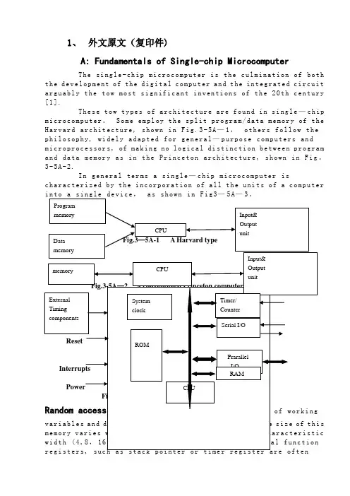
1、外文原文(复印件)A: Fundamentals of Single-chip MicrocomputerTh e si ng le-ch i p mi cr oc om pu ter is t he c ul mi nat i on o f bo th t h e d ev el op me nt o f th e d ig it al com p ut er an d t he int e gr at ed ci rc ui ta r gu ab ly th e t ow m os t s i gn if ic ant i nv en ti on s o f t h e 20t h c en tu ry[1].Th es e to w t ype s o f a rc hi te ct ur e a re fo un d i n s i ng le—ch ip m i cr oc om pu te r。
S o me em pl oy th e s p li t p ro gr am/d at a me mo ry of t he H a rv ar d ar ch it ect u re, sh ow n in Fi g.3-5A—1,ot he r s fo ll ow t hep h il os op hy, wi del y a da pt ed f or ge n er al—pu rp os e c o mp ut er s an dm i cr op ro ce ss or s, of ma ki ng no lo gi c al di st in ct io n be tw ee n p ro gr am a n d da ta m em or y a s i n th e Pr in cet o n ar ch it ec tu re,sh ow n in F ig。
3-5A-2.In g en er al te r ms a s in gl e—ch i p mi cr oc om pu ter isc h ar ac te ri zed b y the i nc or po ra tio n of al l t he uni t s o f a co mp ut er i n to a s in gl e de v i ce,as s ho wn i n F ig3—5A—3。
外文翻译--可编程逻辑控制器介绍What is a PLC?A PLC (i.e. Programmable Logic Controller) is a device that was invented to replace the necessary sequential relay circuits for machine control. The PLC works by looking at its inputs and depending upon their state, turning on/off its outputs. The user enters a program, usually via software, that gives the desired results. PLCs are used in many "real world" applications. If there is industry present, chances are good that there is a plc present. If you are involved in machining, packaging, material handling, automated assembly or countless other industries you are probably already using them. If you are not, you are wasting money and time. Almost any application that needs some type of electrical control has a need for a plc. For example, let's assume that when a switch turns on we want to turn a solenoid on for 5 seconds and then turn it off regardless of how long the switch is on for. We can do this with a simple external timer. But what if the process included 10 switches and solenoids? We would need 10 external timers. What if the process also needed to count how many times the switches individually turned on? We need a lot of external counters.As you can see the bigger the process the more of a need we have for a PLC. We can simply program the PLC to count its inputs and turn the solenoids on for the specified time.PLC HistoryIn the late 1960's PLCs were first introduced. The primary reasonfor designing such a device was eliminating the large cost involved in replacing the complicated relay based machine control systems. Bedford Associates (Bedford, MA) proposed something called a Modular Digital Controller (MODICON) to a major US car manufacturer. Other companies at the time proposed computer based schemes, one of which was based upon the PDP-8. The MODICON 084 brought the world's first PLC into commercial production.When production requirements changed so did the control system. This becomes very expensive when the change is frequent. Since relays are mechanical devices they also have a limited lifetime which requiredstrict adhesion to maintenance schedules.Troubleshooting was also quite tedious when so many relays are involved. Now picture a machine control panel that included many, possibly hundreds or thousands, of individual relays. The size could be mind boggling. How about the complicated initial wiring of so many individual devices! These relays would be individually wired together in a manner that would yield the desired outcome. Were there problems? You bet!These "new controllers" also had to be easily programmed by maintenance and plant engineers. The lifetime had to be long and programming changes easily performed. They also had to survive the harsh industrial environment. That's a lot to ask! The answers were to use aprogramming technique most people were already familiar with and replace mechanical parts with solid-state ones.In the mid70's the dominant PLC technologies were sequencer state-machines and the bit-slice based CPU. The AMD 2901 and 2903 were quite popular in Modicon and A-B PLCs. Conventional microprocessors lacked the power to quickly solve PLC logic in all but the smallest PLCs. As conventional microprocessors evolved, larger and larger PLCs were being based upon them. However, even today some are still based upon the 2903.(ref A-B's PLC-3) Modicon has yet to build a faster PLC than their 984A/B/X which was based upon the 2901.Communications abilities began to appear in approximately 1973. The first such system was Modicon's Modbus. The PLC could now talk to other PLCs and they could be far away from the actual machine they were controlling. They could also now be used to send and receive varying voltages to allow them to enter the analog world. Unfortunately, the lack of standardization coupled with continually changing technology has made PLC communications a nightmare of incompatible protocols and physical networks. Still, it was a great decade for the PLC!The 80's saw an attempt to standardize communications with General Motor's manufacturing automation protocol(MAP). It was also a time for reducing the size of the PLC and making them software programmable through symbolic programming on personal computers instead of dedicated programming terminals or handheld programmers. Today the world's smallest PLC is about the size of a single control relay!The 90's have seen a gradual reduction in the introduction of new protocols, and the modernization of the physical layers of some of the more popular protocols that survived the 1980's. The latest standard has tried to merge plc programming languagesunder one international standard. We now have PLCs that are programmable in function block diagrams, instruction lists, C and structured text all at the same time! PC's are also being used toreplace PLCs in some applications. The original company who commissioned the MODICON 084 has actually switched to a PC based control system.What will the 00's bring? Only time will tell.PLC OperationA PLC works by continually scanning a program. We can think of this scan cycle as consisting of 3 important steps. There are typically more than 3 but we can focus on the important parts and not worry about the others. Typically the others are checking the system and updating the current internal counter and timer values. Step 1-CHECK INPUT STATUS-First the PLC takes a look at each input to determine if it is on or off. In other words, is the sensor connected to the first input on? How about the second input? How about the third... It records this data into its memory to be used during the next step.Step 2-EXECUTE PROGRAM-Next the PLC executes your program oneinstruction at a time. Maybe your program said that if the firstinput was on then it should turn on the first output. Since it already knows which inputs are on/off from the previous step it will be able todecide whether the first output should be turned on based on the state of the first input. It will store the execution results for use later during the next step.Step 3-UPDATE OUTPUT STATUS-Finally the PLC updates the status ofthe outputs. It updates the outputs based on which inputs were on during the first step and the results of executing your program during the second step. Based on the example in step 2 it would now turn on thefirst output because the first input was on and your program said to turn on the first output when this condition is true. After the third step the PLC goes back to step one and repeats the steps continuously. One scan time is defined as the time it takes to execute the 3 steps listed above.PLC advantagesNow that we understand how the PLC processes inputs, outputs, andthe actual program we are almost ready to start writing a program. But first lets see how a relay actually works. After all, the main purpose of a plc is to replace "real-world" relays. We can think of a relay as an electromagnetic switch. Apply a voltage to the coil and a magnetic field is generated. This magnetic field sucks the contacts of the relay in, causing them to make a connection. These contacts can be considered to be a switch. They allow current to flow between 2 points thereby closing the circuit. Let's consider the following example. Here we simply turn on a bell (Lunch time!) whenever a switch is closed. We have 3 real-world parts. A switch, a relay and a bell. Whenever the switchcloses we apply a current to a bell causing it to sound. Notice in the picture that we have 2 separate circuits. The bottom(blue) indicates the DC part. The top(red) indicates the AC part.Here we are using a dc relay to control an AC circuit. That's thefun of relays! When the switch is open no current can flow through the coil of the relay. As soon as the switch is closed, however, currentruns through the coil causing a magnetic field to build up. This magnetic field causes the contacts of the relay to close. Now AC current flows through the bell and we hear it. Lunch time!Next, lets use a plc in place of the relay. (Note that this mightnot be very cost effective for this application but it does demonstrate the basics we need.) The first thing that's necessary is to createwhat's called a ladder diagram. After seeing a few of these it will become obvious why its called a ladder diagram. We have to create one of these because, unfortunately, a plc doesn't understand a schematic diagram. It only recognizes code. Fortunately most PLCs have software which convert ladder diagrams into code. This shields us from actually learning the plc's code. First step- We have to translate all of the items we're using into symbols the plc understands. The plc doesn't understand terms like switch, relay, bell, etc. It prefers input, output, coil, contact, etc. It doesn't care what the actual input or output device actually is. It only cares that its an input or an output.First we replace the battery with a symbol. This symbol is common to all ladder diagrams. We draw what are called bus bars. These simply looklike two vertical bars. One on each side of the diagram. Think of theleft one as being + voltage and the right one as being ground. Further think of the current (logic) flow as being from left toright.Next we give the inputs a symbol. In this basic example we have one real world input. (i.e. the switch) We give the input that the switchwill be connected to, to the symbol shown below. This symbol can also be used as the contact of a relay.A contact symbolNext we give the outputs a symbol. In this example we use one output (i.e. the bell). We give the output that the bell will be physically connected to the symbol shown below. This symbol is used as the coil of a relay.A coil symbolThe AC supply is an external supply so we don't put it in our ladder. The plc only cares about which output it turns on and not what's physically connected to it. Second step- We must tell the plc where everything is located. In other words we have to give all the devices an address. Where is the switch going to be physically connected to the plc? How about the bell? We start with a blank road map in the PLCs town and give each item an address. Could you find your friends if you didn't know their address? You know they live in the same town but which house?The plc town has a lot of houses (inputs and outputs) but we have to figure out who lives where (what device is connected where). We'll get further into the addressing scheme later. The plc manufacturers each do it a different way! For now let's say that our input will be called "0000". The output will be called "500".Final step- We have to convert the schematic into a logical sequence of events. This is much easier than it sounds. The program we're going to write tells the plc what to do when certain events take place. In our example we have to tell the plc what to do when the operator turns on the switch. Obviously we want the bell to sound but the plc doesn't know that. It's a pretty stupid device, isn't it!The picture above is the final converted diagram. Notice that we eliminated the real world relay from needing a symbol. It's actually "inferred" from the diagram. Huh? Don't worry, you'll see what we mean as we do more examples.1.PLC是什么PLC ,即可编程逻辑控制器,是发明用于取代必要的顺序继电器的机器控制电路一种装臵。
可编程控制器本科毕业论文中英文翻译材料关于PLC外文翻译中文翻译可编程控制器技术可编程序控制器(Programmable Logic Controller,习惯上简称为PLC)是以微处理器为核心的通用工业自动化装置。
是20世纪60年代末在继电器控制系统的基础上开发出来的,它将传统的继电器控制技术与计算机技术和通信技术融为一体,具有结构简单、性能优越、可靠性高、灵活通用、易于编程、使用方便等优点。
具体来说,PLC的特点表现为以下几个方面:?硬件的可靠性高。
PLC专业在工业环境的恶劣条件下应用而设计。
一个设计良好的PLC能置于有很强电噪声、电磁干扰、机械振动、极端温度和湿度很大的环境中。
在硬件设计方面,首先是选用优质器件,再就是采用合理的系统结构,加固、简化安装,使它易于抗振冲击,对印刷电路板的设计、加工和焊接都采取了极为严格的工艺措施,而在电路、结构及工艺上采取了一些独特的方式。
由于PLC 本身具有很高的可靠性,所以在发生故障的部位大多集中在输入/输出的部位以及如传感器件、限位开关、光电开关、电磁阀、电机等外围装置上。
?编程简单,使用方便。
用微机实现自动控制,常使用汇编语言编程,难于掌握,要求使用者具有一定水平的计算机硬件和软件知识。
PLC采用面向控制过程、面向问题的编程方式,与目前微机控制常用的汇编语言相比,虽然在PLC内部增加了解释程序,增加了程序的执行时间,但对大多数的机电控制设备来说,这种损耗是微不足道的。
?接线简单,通用性好。
在电信号匹配的情况下,PLC的接线只需将输入信号的设备(按钮、开关等)与PLC输入端子连接,将接受输出信号执行控制任务的执行元件(接触器、电磁阀)与PLC输出端子连接。
接线简单、工作量少,省去了传统的继电器控制系统的接线和拆线的麻烦。
PLC的编程逻辑提供了能随要求而改变的逻辑关系,这样生产线的自动化过程就能随意改变。
这种性能使PLC具有很高的经济效益。
用于连接现场设备的硬件接口实际上已经设计成为PLC的组成部分,模块化的自诊断接口电路能指出故障,并易于排除故障与替换故障部件,这样的软硬件设计就使现场电气人员与技术人员易于使用。
中文3475字Control Devices and PLCJoseph La FauciFrom Wikipedia, the free encyclopediaSeveral types of control devices are used in industry to satisfy the following control needs. Mechanical Control、Pneumatic Control、Electromechanical Control、Electronic Control、Computer Control、Programmable Logic Control (PLC)Mechanical control includes cams and governors. Although they have been used for the control of very complex machines, to be cost effectively, today they are used for simple and fixed-cycle task control. Some automated machines, such as screw machines, still use cam-based control. Mechanical control is difficult to manufacture and is subject to wear. Pneumatic control is still very popular for certain applications. It uses compressed air, valves, and switches to construct simple control logic, but is relatively slow. Because standard components are used to construct the logic, it is easier to build than a mechanical control. Pneumatic control parts are subject to wear.As does a mechanical control, an electromechanical control use switches, relays, timers, counters, and so on, to construct logic. Because electric current is used, it is faster and more flexible. The controllers using electromechanical control are called relay devices.Electric control is similar to electromechanical control, except that the moving mechanical components in an electromechanical control device are replaced by electronic switches, which works faster and is more reliable.Computer control is the most versatile control system. The logic of the control is programmed into the computer memory using software. It not only can be for machine and manufacturing system control, but also for data communication. Very complex control strategies with extensive computations can be programmed. The first is the interface with the outside world. Internally, the computer uses a low voltage (5 to 12 volts) and a low current (several milliamps). Machine requires much higher voltages (24, 110, or 220 voltages) and currents (measured in amps). The interface not only has to convert the voltage difference, but also must filter out the electric noise usually found in the shop. The interface thus must be custom-built for each application.In order to use the advantages of all those controllers and eliminate the difficulties, the programmable logic controllers were invented. A PLC was a replacement for relay devices. They are programmed using a ladder diagram, which is standard electric wiring diagram. As PLCs become more flexibility, high-level as well as low-level languages are available to PLC programmers. PLCs have the flexibility of computers as well as a standard and easy interface with processes and other devices. They are widely accepted in industry for controlling from a single device to a complex manufacturing facility.Automatic of many different processes, such as controlling machines or factory assembly lines, is done through the use of small the computers called a programmable logic controller (PLC), PLCs were first created to serve the automobile industry, and the first PLC project was developed in 1968 for General Motors to replace hard-wired relay systems with an electronic controller. Since the advent of PLCs, the ability to centralize factory processes, especially in the automotive industry, has improved greatly.Automatic control has become an important consideration in most industrial processes where certain repetitive operations are performed. This applies to situations such as the automatic assembly of modules and products where a cycle of events is conducted in a consistent and uniform manner. Applications generally include a combination of feeding, handing, drilling, cutting, assembling, discharging, inspecting, packaging and transporting by conveyor.Prior to the introduction of computer-based control systems the automation of such events was achieved by using either electrical relay logic circuits or pneumatic logic circuits. Althoughthese are conceptionally simple and easy to maintain, they are somewhat bulky and can be expensive. More important is the fact that the resulting control circuits are inflexible and do not lend themselves to easy system control alterations.The late 1960s saw the introduction of the programmable logic controller (PLC) as a direct replacement for the relay sequence controllers. In essence the PLC replaces the hardwired relay or pneumatic logic with a more flexible programmable logic. It offers a simple, flexible and low-cost means of implementing a sequence control strategy where outputs for switching devices on and off are set according to input conditions as read from digital sensor states. It should be noted that, particularly in the USA, the PLC is often referred to as a ‘programmable controller’ with the abbreviation of PC. It should not be confused with the personal computer ‘PC’ or IBM-PC.The PLC is composed of the same ingredients as a microcomputer such as a microprocessor, memory and input/output facilities. The processor executes the instructions held in memory by operating on inputs derived from the controlled process and providing outputs in accordance with the logic sequence defined in the control program. Its basic principle of operation during the execution of the program is that the program is scanned very fast, typically 1 to 20 us per step, to record all input states. The outputs are then set according to the logic specified in the program. The sequence is continually repeated for each scan period of the controller.Small PLCs dedicated to sequential control have typically 12 inputs and 8 outputs with the possibility of expansion up to 128 I/O lines. They come complete with an input interface to accommodate a range of input signals from the controlled process which are then converted to an appropriate from for the processor. Similarly, provision is made at the output of the PLC to interface with a variety of process hardware such as lamps, motors, relays and solenoids. The typical handing voltages are 24V DC and 110V AC.Program instructions can be input into the battery backup RAM of a PLC by means of either a hand-held programming keypad or a connected PC with an appropriate software development package. Some LCD programming consoles incorporate a limited graphical display which illustrates the program in ladder logic format as the programmer builds it up using symbolic keys. This is also the principle of the PC-based development system where additionally the programmer has access to a lager visual display and the PC’s disk operating system for data storage and retrieval. Once the program has been debugged and the control strategy verified by simulation, the codes can be loaded into an erasable and programmable read only memory chip (EPROM) which can then be installed in the PLC.There are a large number of manufacturers of PLCs. Although some use their own particular software language the majority are based on the ladder logic diagram. Historically this was introduced in order to gain the acceptance of customers who were interested in moving from hardwired relay control systems to the PLC. In addition to the basic input/output facilities the PLC also contains timers, counters and other special functions.As PLC technology has advanced, so have programming languages and communications capabilities, along with many other important features. Today’s PLCs offer faster scan times, space efficient high-density input/output systems, and special interfaces to allow non-traditional devices to be attached directly to the PLC. Not only can they communicate with other control systems, they can also perform reporting functions and diagnose their own failures, as well as the failure of a machine or process.Size is typically used to categorize today’s PLC, and is often an indication of the features and types of applications it will accommodate. Small, non-modular PLCs (also known as fixed I/O PLCs) generally have less memory and accommodate a small number of inputs and outputs in fixed configurations. Modular PLCs have bases or racks that allow installation of multiple I/O modules, and will accommodate more complex application.When you consider all of the advances PLCs have made and all the benefits they offer, it’s easy to see how they’ve become a standard in the industry, and why they will most likelycontinue their success in the future.Communicating with a variety of other control devices has not been strength of traditional PLC networks. Many industrial controllers are quipped with an RS232 serial port for the transfer of data to and from other digital control devices in a system.PLCs face ever more complex challenges these days. Where once they quietly replaced relays and gave an occasional report to a corporate mainframe, they are now grouped into cells, given new jobs and new languages, and are force to compete against a growing array of control products. For this year’s annual PLC technology update, we queried PLC makers on these topics and more.Higher level PLC programming languages have been around for some time, but lately their popularity has been mushrooming. As Raymond Leveille, vice president & general manager, Siemens Energy & Automation, Inc. Programmable Controls Division, points out: “As programmable controls are being used for more and more sophisticated operations, languages other than ladder logic become more practical, efficient, and powerful. For example, it’s very difficult to write a trigonometric function using ladder logic.”Language gaining acceptance includes Boolean, control system flowcharting, and such function chart languages as Graphcet and its variations. And there’s increasing interest in languages like C and BASIC.Thus far, PLCs have not been used extensively for continuous process control. Will this continue? “The feeling that I’ve gotten,” says Ken Jannotta, manager, product planning, Series one and Series Six product, at GE Fanuc North America, “is that PLCs will be used in the process industry but not necessarily for process control.”Several vendors-obviously betting that the opposite will happen-have introduced PLCs optimized for process applications. Rich Ryan, manager, commercial marketing, Allen-bradley Programmable Controls Div. cites PLCs’ increasing use in such industries as food, chemicals, and petroleum.While there are concerns about the lack of compatible communications between PLCs from different vendors, the connection at the other end-the I/O-is even more fragmented. With rare exceptions, I/O is still proprietary. Yet there are those who feel that I/O will eventually become more universal. GE Fanuc is hoping to do that with its Genius smart I/O line. The independent I/O makers are pulling in the same direction.Many say that I/O is such a high-value item that PLC makers will always want to keep it proprietary. As Ken Jannotta, says: “The I/O is going to be a disproportionate amount of the hardware sale. Certainly each PLC vendor is going to try to protect that.” For that reason, he says, PLC makers won’t begin selling universal I/O systems from other vendors. “If we start selling that kind of product,” says Jannotta, “what do we manufacture?”With more intelligent I/O appearing, Sal Provanzano feels this will lead to more differentiation among I/O from different makers. “Where the I/O becomes extremely intelligent and becomes part of the system,” he says, “it really is hard to define which is the I/O and which is the CPU. It really starts to become distributed processing. Now, in order for that distributed processing to work, the CPU, if you will, is equally integrated into the system as the I/O.”While different PLCs probably will continue to use proprietary I/O, several vendors make it possible to connect their I/O to IBM PC (personal computer)-compatible equipment. Allen-bradley, Gould, and Cincinnati Milacron already have, and rumor has it that GE is planning something along these same lines.“There are inherent architectural differences between a general purpose computer,”says Rich Ryan, “and a programmable controller. There are hardware constructs built into almost every manufacturer’s programmable controller today that customize the hardware to run ladder logic and to solve machine code.”One fundamental difference he cites is called state of the machine. Ryan: “When you shut the machine off, or interrupt the cycle, or you jump to another spot in the cycle, programmable controllers inherently remember the state of the machine: what the timers were, what the counters were, and what the states of all the latches were. Computersdon’t inherently do that.”附录B 中文翻译控制装置和可编程逻辑控制维基自由百科全书工业用的几种控制装置是为了满足以下一些控制要求:机械控制、气动控制、机电控制、电子控制、计算机控制、可编程控制。
Programmable Logic ControllerA programmable logic controller (PLC) or programmable controller is a digital computer used for automation of electromechanical processes, such as control of machinery on factory assembly lines, amusement rides, or lighting fixtures. PLCs are used in many industries and machines. Unlike general-purpose computers, the PLC is designed for multiple inputs and output arrangements, extended temperature ranges, immunity to electrical noise, and resistance to vibration and impact. Programs to control machine operation are typically stored in battery-backed or non-volatile memory. A PLC is an example of a real time system since output results must be produced in response to input conditions within a bounded time, otherwise unintended operation will result.1.HistoryThe PLC was invented in response to the needs of the American automotive manufacturing industry. Programmable logic controllers were initially adopted by the automotive industry where software revision replaced the re-wiring of hard-wired control panels when production models changed.Before the PLC, control, sequencing, and safety interlock logic for manufacturing automobiles was accomplished using hundreds or thousands of relays, cam timers, and drum sequencers and dedicated closed-loop controllers. The process for updating such facilities for the yearly model change-over was very time consuming and expensive, as electricians needed to individually rewire each and every relay.In 1968 GM Hydramatic (the automatic transmission division of General Motors) issued a request for proposal for an electronic replacement for hard-wired relay systems. The winning proposal came from Bedford Associates of Bedford, Massachusetts. The first PLC, designated the 084 because it was Bedford Associates' eighty-fourth project, was the result. Bedford Associates started a new company dedicated to developing, manufacturing, selling, and servicing this new product: Modicon, which stood for MOdular DIgital CONtroller. One of the people who worked on that project was Dick Morley, who is considered to be the "father" of thePLC. The Modicon brand was sold in 1977 to Gould Electronics, and later acquired by German Company AEG and then by French Schneider Electric, the current owner.One of the very first 084 models built is now on display at Modicon's headquarters in North Andover, Massachusetts. It was presented to Modicon by GM, when the unit was retired after nearly twenty years of uninterrupted service. Modicon used the 84 moniker at the end of its product range until the 984 made its appearance.The automotive industry is still one of the largest users of PLCs.2.DevelopmentEarly PLCs were designed to replace relay logic systems. These PLCs were programmed in "ladder logic", which strongly resembles a schematic diagram of relay logic. This program notation was chosen to reduce training demands for the existing technicians. Other early PLCs used a form of instruction list programming, based on a stack-based logic solver.Modern PLCs can be programmed in a variety of ways, from ladder logic to more traditional programming languages such as BASIC and C. Another method is State Logic, a very high-level programming language designed to program PLCs based on state transition diagrams.Many early PLCs did not have accompanying programming terminals that were capable of graphical representation of the logic, and so the logic was instead represented as a series of logic expressions in some version of Boolean format, similar to Boolean algebra. As programming terminals evolved, it became more common for ladder logic to be used, for the aforementioned reasons. Newer formats such as State Logic and Function Block (which is similar to the way logic is depicted when using digital integrated logic circuits) exist, but they are still not as popular as ladder logic.A primary reason for this is that PLCs solve the logic in a predictable and repeating sequence, and ladder logic allows the programmer (the person writing the logic) to see any issues with the timing of the logic sequence more easily than would be possible in other formats.3.ProgrammingEarly PLCs, up to the mid-1980s, were programmed using proprietary programming panels or special-purpose programming terminals, which often had dedicated function keys representing the various logical elements of PLC programs.Programs were stored on cassette tape cartridges. Facilities for printing and documentation were very minimal due to lack of memory capacity. The very oldest PLCs used non-volatile magnetic core memory.More recently, PLCs are usually programmed using special application software written for use on desktop computers, and connecting between the desktop computer and the PLC such as via Ethernet or RS-232 cabling. Such software allows entry and editing of the ladder style logic, and then may provide additional functionality to assist debugging and troubleshooting the software, for example by highlights portions of the logic to show current status during operation or via simulation. Finally, the software may allow uploading and downloading of the program between the computer and the PLC, for backup and restoration purposes. Alternately, specific devices known as programming boards are used to hard wire the logic into the controller by the use of a removable chip, such as an EEPROM, where the program is transferred to the programming board from the workstation via serial or other bus logic.4.FunctionalityThe functionality of the PLC has evolved over the years to include sequential relay control, motion control, process control, distributed control systems and networking. The data handling, storage, processing power and communication capabilities of some modern PLCs are approximately equivalent to desktop computers. PLC-like programming combined with remote I/O hardware, allow a general-purpose desktop computer to overlap some PLCs in certain applications. Regarding the practicality of these desktop computer based logic controllers, it is important to note that they have not been generally accepted in heavy industry because the desktop computers run on less stable operating systems than do PLCs, and because the desktop computer hardware is typically not designed to the same levels of tolerance to temperature, humidity, vibration, and longevity as the processors used in PLCs. In addition to the hardware limitations of desktop based logic, operating systems such as Windows do not lend themselves to deterministic logic execution, with the result that the logic may not always respond to changes in logic state or input status with the extreme consistency in timing as is expected from PLCs. Still, such desktop logic applications find use in less critical situations, such as laboratory automation and use in small facilities where the application is less demanding and critical, because they are generally much less expensive than PLCs.In more recent years, small products called PLRs (programmable logic relays), and also by similar names, have become more common and accepted. These are verymuch like PLCs, and are used in light industry where only a few points of I/O (i.e. a few signals coming in from the real world and a few going out) are involved, and low cost is desired. These small devices are typically made in a common physical size and shape by several manufacturers, and branded by the makers of larger PLCs to fill out their low end product range. Popular names include PICO Controller, NANO PLC, and other names implying very small controllers. Most of these have between 8 and 12 digital inputs, 4 and 8 digital outputs, and up to 2 analog inputs. Size is usually about 4" wide, 3" high, and 3" deep. Most such devices include a tiny postage stamp sized LCD screen for viewing simplified ladder logic (only a very small portion of the program being visible at a given time) and status of I/O points, and typically these screens are accompanied by a 4-way rocker push-button plus four more separate push-buttons, similar to the key buttons on a VCR remote control, and used to navigate and edit the logic. Most have a small plug for connecting via RS-232 to a personal computer so that programmers can use simple Windows applications for programming instead of being forced to use the tiny LCD and push-button set for this purpose. Unlike regular PLCs that are usually modular and greatly expandable, the PLRs are usually not modular or expandable, but their price can be two orders of magnitude less than a PLC and they still offer robust design and deterministic execution of the logic.5.FeaturesThe main difference from other computers is that PLCs are armored for severe conditions (such as dust, moisture, heat, cold) and have the facility for extensive input/output (I/O) arrangements. These connect the PLC to sensors and actuators. PLCs read limit switches, analog process variables (such as temperature and pressure), and the positions of complex positioning systems. Some use machine vision. On the actuator side, PLCs operate electric motors, pneumatic or hydraulic cylinders, magnetic relays, solenoids, or analog outputs. The input/output arrangements may be built into a simple PLC, or the PLC may have external I/O modules attached to a computer network that plugs into the PLC.6.System styleA small PLC will have a fixed number of connections built in for inputs and outputs. Typically, expansions are available if the base model has insufficient I/O.Modular PLCs have a chassis (also called a rack) into which are placed modules with different functions. The processor and selection of I/O modules is customised for the particular application. Several racks can be administered by a single processor, and may have thousands of inputs and outputs. A special high speed serial I/O link is used so that racks can be distributed away from the processor, reducing the wiring costs for large plants.7.PLC compared with other control systemsPLCs are well-adapted to a range of automation tasks. These are typically industrial processes in manufacturing where the cost of developing and maintaining the automation system is high relative to the total cost of the automation, and where changes to the system would be expected during its operational life. PLCs contain input and output devices compatible with industrial pilot devices and controls; little electrical design is required, and the design problem centers on expressing the desired sequence of operations. PLC applications are typically highly customized systems so the cost of a packaged PLC is low compared to the cost of a specific custom-built controller design. On the other hand, in the case of mass-produced goods, customized control systems are economic due to the lower cost of the components, which can be optimally chosen instead of a "generic" solution, and where the non-recurring engineering charges are spread over thousands or millions of units.For high volume or very simple fixed automation tasks, different techniques are used. For example, a consumer dishwasher would be controlled by an electromechanical cam timer costing only a few dollars in production quantities.A microcontroller-based design would be appropriate where hundreds or thousands of units will be produced and so the development cost (design of power supplies, input/output hardware and necessary testing and certification) can be spread over many sales, and where the end-user would not need to alter the control. Automotive applications are an example; millions of units are built each year, and very few end-users alter the programming of these controllers. However, some specialty vehicles such as transit busses economically use PLCs instead of custom-designed controls, because the volumes are low and the development cost would be uneconomic.Very complex process control, such as used in the chemical industry, may require algorithms and performance beyond the capability of even high-performance PLCs. Very high-speed or precision controls may also require customized solutions; for example, aircraft flight controls.Programmable controllers are widely used in motion control, positioning control and torque control. Some manufacturers produce motion control units to be integrated with PLC so that G-code (involving a CNC machine) can be used to instruct machine movements.PLCs may include logic for single-variable feedback analog control loop, a "proportional, integral, derivative" or "PID controller." A PID loop could be used to control the temperature of a manufacturing process, for example. Historically PLCs were usually configured with only a few analog control loops; where processes required hundreds or thousands of loops, a distributed control system (DCS) would instead be used. As PLCs have become more powerful, the boundary between DCS and PLC applications has become less distinct.PLCs have similar functionality as Remote Terminal Units. An RTU, however, usually does not support control algorithms or control loops. As hardware rapidly becomes more powerful and cheaper, RTUs, PLCs and DCSs are increasingly beginning to overlap in responsibilities, and many vendors sell RTUs with PLC-like features and vice versa. The industry has standardized on the IEC 61131-3 functional block language for creating programs to run on RTUs and PLCs, although nearly all vendors also offer proprietary alternatives and associated development environments.可编程控制器可编程逻辑控制器(PLC)或可编程控制器是一种数字化的计算机,机电流程自动化应用,如机械控制的工厂流水线,机动游戏,或照明装置。
编号英文原文PLC technique discussion and future development Along with the development of the ages, the technique that is nowadays is also gradually perfect, the competition plays more strong; the operation that list depends the artificial has already can't satisfied with the current manufacturing industry foreground, also can't guarantee the request of the higher quantity and high new the image of the technique business enterprise.The people see in produce practice, automate brought the tremendous convenience and the product quantities for people up of assurance, also eased the personnel's labor strength, reduce the establishment on the personnel. The target control of the hard realization in many complicated production lines, whole and excellent turn, the best decision etc., well-trained operation work, technical personnel or expert, governor but can judge and operate easily, can acquire the satisfied result. The research target of the artificial intelligence makes use of the calculator exactly to carry out, imitate these intelligences behavior, moderating the work through person's brain and calculators, with the mode that person's machine combine, for resolve the very complicated problem to look for the best pathWe come in sight of the control that links after the electric appliances in various situation, that is already the that time generation past, now of after use in the mold a perhaps simple equipments of grass-roots control that the electric appliances can do for the low level only; And the PLC emergence also became the epoch-making topic, adding the vivid software control through a very and stable hardware, making the automation head for the new high tide.The PLC biggest characteristics lie in: The electrical engineering teacher already no longer electric hardware up too many calculations of cost, as long as order the importation that the button switch or the importation of the sensors order to link the PLC up can solve problem, pass to output to order the conjunction contact machine or control the start equipments of the big power after the electric appliances, but the exportation equipments direct conjunction of the small power can.PLC internal containment have the CPU of the CPU, and take to have an I/ O for expand of exterior to connect a people's address and saving machine three big pieces to constitute, CPU core is from an or many is tired to add the machine to constitute, mathematics that they have the logic operation ability, and can read the procedure save the contents of the machine to drive the homologous saving machine and I/ Os to connect after pass the calculation; The I/ O add inner part is tired the input and output system of the machine and exterior link, and deposit the related data into the procedure saving machine or data saving machine; The saving machine can depositthe data that the I/ O input in the saving machine, and in work adjusting to become tired to add the machine and I/ Os to connect, saving machine separately saving machine RAM of the procedure saving machine ROM and dates, the ROM can do deposit of the data permanence in the saving machine, but RAM only for the CPU computes the temporary calculation usage of hour of buffer space.The PLC anti- interference is very and excellent, our root need not concern its service life and the work situation bad, these all problems have already no longer become the topic that we fail, but stay to our is a concern to come to internal resources of make use of the PLC to strengthen the control ability of the equipments for us, make our equipments more gentle.PLC language is not we imagine of edit collected materials the language or language of Cs to carry on weaving the distance, but the trapezoid diagram that the adoption is original after the electric appliances to control, make the electrical engineering teacher while weaving to write the procedure very easy comprehended the PLC language, and a lot of non- electricity professional also very quickly know and go deep into to the PLC.Is PLC one of the advantage above and only, this is also one part that the people comprehend more and easily, in a lot of equipments, the people have already no longer hoped to see too many control buttons, they damage not only and easily and produce the artificial error easiest, small is not a main error perhaps you can still accept; But lead even is a fatal error greatly is what we can't is tolerant of. New technique always for bringing more safe and convenient operation for us, make we a lot of problems for face on sweep but light, do you understand the HMI? Says the HMI here you basically not clear what it is, also have no interest understanding, change one inside text explains it into the touch to hold or man-machine interface you knew, and it combines with the PLC to our larger space.HMI the control not only is reduced the control press button, increase the vivid of the control, more main of it is can sequence of, and at can the change data input to output the feedback with data, control in the temperature curve of imitate but also can keep the manifestation of view to come out. And can write the function help procedure through a plait to provide the help of various what lies in one's power, the one who make operate reduces the otiose error. Currently the HMI factory is also more and more, the function is also more and more strong, the price is also more and more low, and the noodles of the usage are wide more and more. The HMI foreground can say that think ° to be good very.At a lot of situations, the list is a smooth movement that can't guarantee the equipments by the control of the single machine, but pass the information exchanges of the equipments and equipments to attain the result that we want. For example fore pack and the examination of the empress work preface, we will arrive wrapping information feedback to examine the place, and examine the information of the place to also want the feedback to packing. Pass the information share thus to make both the chain connect, becoming a total body, the match of your that thus make is more close, at each other attain to reflect the result that mutually flick.The PLC correspondence has already come more body now its value, at the PLC andcorrespondence between PLCs, can pass the communication of the information and the share of the dates to guarantee that of the equipments moderates mutually, the result that arrive already to repair with each other. Data conversion the adoption RS232 between PLC connect to come to the transmission data, but the RS232 pick up a people and can guarantee 10 meters only of deliver the distance, if in the distance of 1000 meters we can pass the RS485 to carry on the correspondence, the longer distance can pass the MODEL only to carry on deliver.The PLC data transmission is just to be called a form to it in a piece of and continuous address that the data of the inner part delivers the other party, we, the PLC of the other party passes to read data in the watch to carry on the operation. If the data that data in the watch is a to establish generally, that is just the general data transmission, for example today of oil price rise, I want to deliver the price of the oil price to lose the oil ally on board, that is the share of the data; But take data in the watch for an instruction procedure that controls the PLC, that had the difficulty very much, for example you have to control one pedestal robot to press the action work that you imagine, you will draw up for it the form that a procedure combine with the data sends out to pass by.The form that information transport contain single work, the half a work and the difference of a workers .The meaning of the single work also is to say both, a can send out only, but a can receive only, for example a spy he can receive the designation of the superior only, but can't give the superior reply; A work of half is also 2 and can send out similar to accept the data, but can't send out and accept at the same time, for example when you make a phone call is to can't answer the phone, the other party also; But whole pair works is both can send out and accept the data, and can send out and accept at the same time. Be like the Internet is a typical example.The process that information transport also has synchronous and different step cent: The data line and the clock lines are synchronous when synchronous meaning lie in sending out the data, is also the data signal and the clock signals to be carry on by the CPU to send out at the same time, this needs to all want the specialized clock signal each other to carry on the transmission and connect to send, and is constrained, the characteristics of this kind of method lies in its speed very quick, but correspond work time of take up the CPU and also want to be long oppositely, at the same time the technique difficulty also very big. Its request lies in canting have an error margins in a dates deliver, otherwise the whole piece according to compare the occurrence mistake, this on the hardware is a bigger difficulty. Applied more and more extensive in some appropriative equipments, be like the appropriative medical treatment equipments, the numerical signal equipments...etc., in compare the one data deliver, its result is very good.And the different step is an application the most extensive, this receive benefit in it of technique difficulty is opposite and want to be small, at the same time not need to prepare the specialized clock signal, its characteristics to lie in, its data is partition, the long-lost send out and accept, be the CPU is too busy of time can grind to a stop sex to work, also reduced the difficulty on the hardware, the data throw to lose at the same time opposite want to be little, we can pass the examination of the data to observe whether the data that we send out has the mistake or not, belike strange accidentally the method, tired addition and eight efficacies method etc., can use to helps whether the data that we examine to send out have or not the mistake occurrence, pass the feedback to carry on the discriminator.A line of transmission of the information contains a string of and combine the cent of: The usual PLC is 8 machines, certainly also having 16 machines. We can be an at the time of sending out the data a send out to the other party, also can be 88 send out the data to the other party, an and 8 differentiations are also the as that we say to send out the data and combine sends out the data. A speed is more and slowly, but as long as 2 or three lines can solve problem, and can use the telephone line to carry on the long range control. But combine the ocular transmission speed is very quick of, it is a string of ocular of 25600%, occupy the advantage in the short distance, the in view of the fact TTL electricity is even, being limited by the scope of one meter generally, it combine unwell used for the data transmission of the long pull, thus the cost is too expensive.Under a lot of circumstances we are total to like to adopt the string to combine the conversion chip to carry on deliver, under this kind of circumstance not need us to carry on to deposited the machine to establish too and complicatedly, but carry on the data exchanges through the data transmission instruction directly, but is not a very viable way in the correspondence, because the PLC of the other party must has been wait for your data exportation at the time of sending out the data, it can't do other works.When you are reading the book, you hear someone knock on door, you stop to start up of affair, open the door and combine to continue with the one who knock on door a dialogue, the telephone of this time rang, you signal hint to connect a telephone, after connecting the telephone through, return overdo come together knock on door to have a conversation, after dialogue complete, you continue again to see your book, this kind of circumstance we are called the interruption to it, it has the authority, also having sex of have the initiative, the PLC had such function .Its characteristics lie in us and may meet the urgently abrupt affairs in the operation process of the equipments, we want to stop to start immediately up of work, the whereabouts manages the more important affair, this kind of circumstance is we usually meet of, PLC while carry out urgent mission, total will keep the current appearance first, for example the address of the procedure, CPU of tired add the machine data etc., be like to stick down which the book that we see is when we open the door the page or simply make a mark, because we treat and would still need to continue immediately after book of see the behind. The CPU always does the affair that should do according to our will, but your mistake of give it an affair, it also would be same to do, this we must notice.The interruption is not only a, sometimes existing jointly with the hour several inside break, break off to have the preferred Class, they will carry out the interruption of the higher Class according to person's request. This kind of breaks off the medium interruption to also became to break off the set. The Class that certainly break off is relevant according to various resources of CPU with internal PLC, also following a heap of capacity size of also relevant fasten.The contents that break off has a lot of kinds, for example the exterior break off,correspondence in of send out and accept the interruption and settle and the clock that count break off, still have the WDT to reset the interruption etc., they enriched the CPU to respond to the category while handle various business. Speak thus perhaps you can't comprehend the internal structure and operation orders of the interruption completely also, we do a very small example to explain.Each equipment always will not forget a button, it also is at we meet the urgent circumstance use of, which is nasty to stop the button. When we meet the Human body trouble and surprised circumstances we as long as press it, the machine stops all operations immediately, and wait for processing the over surprised empress recover the operation again. Nasty stop the internal I/ O of the internal CPU of the button conjunction PLC to connect up, be to press button an exterior to trigger signal for CPU, the CPU carries on to the I/ O to examine again, being to confirm to have the exterior to trigger the signal, CPU protection the spot breaks off procedure counts the machine turn the homologous exterior I/ O automatically in the procedure to go to also, be exterior interruption procedure processing complete, the procedure counts the machine to return the main procedure to continue to work. Have 1:00 can what to explain is we generally would nasty stop the button of exterior break off to rise to the tallest Class, thus guarantee the safety.When we are work a work piece, giving the PLC a signal, counting PLC inner part the machine add 1 to compute us for a day of workload, a count the machine and can solve problem in brief, certainly they also can keep the data under the condition of dropping the electricity, urging the data not to throw to lose, this is also what we hope earnestly.The PLC still has the function that the high class counts the machine, being us while accept some dates of high speed, the high speed that here say is the data of the in all aspects tiny second class, for example the bar code scanner is scanning the data continuously, calculating high-speed signal of the data processor DSP etc., we will adopt the high class to count the machine to help we carry on count. It at the PLC carries out the procedure once discover that the high class counts the machine to should of interruption, will let go of the work on the hand immediately. The trapezoid diagram procedure that passes by to weave the distance again explains the high class for us to carry out procedure to count machine would automatic performance to should of work, thus rise the Class that the high class counts the machine to high one Class.You heard too many this phrases perhaps:" crash", the meaning that is mostly is a workloadof CPU to lead greatly, the internal resources shortage etc. the circumstance can't result in procedure circulate. The PLC also has the similar circumstance, there is a watchdog WDT in the inner part of PLC, we can establish time that a procedure of WDT circulate, being to appear the procedure to jump to turn the mistake in the procedure movement process or the procedure is busy, movement time of the procedure exceeds WDT constitution time, the CPU turn but the WDT reset the appearance. The procedure restarts the movement, but will not carry on the breakage to the interruption.The PLC development has already entered for network ages of correspondence from the mode of the one, and together other works control the net plank and I/ O card planks to carry onthe share easily. A state software can pass all se hardwires link, more animation picture of keep the view to carries on the control, and cans pass the Internet to carry on the control in the foreign land, the blast-off that is like the absolute being boat No.5 is to adopt this kind of way to make airship go up the sky.The development of the higher layer needs our continuous effort to obtain. The PLC emergence has already affected a few persons fully, we also obtained more knowledge and precepts from the top one experience of the generation, coming to the continuous development PLC technique, push it toward higher wave tide.Knowing the available PLC network options and their best applications will ensure an efficient and flexible control system design.The programmable logic controller's (PLC's) ability to support a range of communication methods makes it an ideal control and data acquisition device for a wide variety of industrial automation and facility control applications. However, there is some confusion because so many possibilities exist. To help eliminate this confusion, let's list what communications are available and when they would be best applied.To understand the PLC's communications versatility, let's first define the terms used in describing the various systems.ASCII: This stands for "American Standard Code for Information Interchange." As shown in Fig. 1, when the letter "A" is transmitted, for instance, it's automatically coded as "65" by the sending equipment. The receiving equipment translates the "65" back to the letter "A." Thus, different devices can communicate with each other as long as both use ASCII code.ASCII module: This intelligent PLC module is used for connecting PLCs to other devices also capable of communicating using ASCII code as a vehicle.Bus topology: This is a linear local area network (LAN) arrangement, as shown in Fig. 2A, in which individual nodes are tapped into a main communications cable at a single point and broadcast messages. These messages travel in both directions on the bus from the point of connection until they are dissipated by terminators at each end of the bus.CPU: This stands for "central processing unit," which actually is that part of a computer, PLC, or other intelligent device where arithmetic and logical operations are performed and instructions are decoded and executed.Daisy chain: This is a description of the connection of individual devices in a PLC network, where, as shown in Fig. 3, each device is connected to the next and communications signals pass from one unit to the next in a sequential fashion.Distributed control: This is an automation concept in which portions of an automated system are controlled by separate controllers, which are located in close proximity to their area of direct control (control is decentralized and spread out over the system).Host computer: This is a computer that's used to transfer data to, or receive data from, a PLC in a PLC/computer network.Intelligent device: This term describes any device equipped with its own CPU.I/O: This stands for "inputs and outputs," which are modules that handle data to the PLC (inputs) or signals from the PLC (outputs) to an external device.Kbps: This stands for "thousand bits per second," which is a rate of measure for electronic data transfer.Mbps: This stands for "million bits per second."Node: This term is applied to any one of the positions or stations in a network. Each node incorporates a device that can communicate with all other devices on the network.Protocol: The definition of how data is arranged and coded for transmission on a network.Ring topology. This is a LAN arrangement, as shown in Fig. 2C, in which each node is connected to two other nodes, resulting in a continuous, closed, circular path or loop for messages to circulate, usually in one direction. Some ring topologies have a special "loop back" feature that allows them to continue functioning even if the main cable is severed.RS232. This is an IEEE standard for serial communications that describes specific wiring connections, voltage levels, and other operating parameters for electronic data communications. There also are several other RS standards defined.Serial: This is an electronic data transfer scheme in which information is transmitted one bit at a time.Serial port: This the communications access point on a device that is set up for serial communications.Star topology. This is a LAN arrangement in which, as shown in Fig. 2B, nodes are connected to one another through a central hub, which can be active or passive. An active hub performs network duties such as message routing and maintenance. A passive central hub simply passes the message along to all the nodes connected to it.Topology: This relates to a specific arrangement of nodes in a LAN in relation to one another.Transparent: This term describes automatic events or processes built into a system that require no special programming or prompting from an operator.Now that we're familiar with these terms, let's see how they are used in describing the available PLC network options.PLC network optionsPLC networks provide you with a variety of networking options to meet specific control and communications requirements. Typical options include remote I/O, peer-to-peer, and host computer communications, as well as LANs. These networks can provide reliable andcost-effective communications between as few as two or as many as several hundred PLCs, computers, and other intelligent devices.Many PLC vendors offer proprietary networking systems that are unique and will not communicate with another make of PLC. This is because of the different communications protocols, command sequences, error-checking schemes, and communications media used by each manufacturer.However, it is possible to make different PLCs "talk" to one another; what's required is anASCII interface for the connection(s), along with considerable work with software.Remote I/0 systemsA remote I/O configuration, as shown in Fig. 4A, has the actual inputs and outputs at some distance from the controller and CPU. This type of system, which can be described as a "master-and-slave" configuration, allows many distant digital and analog points to be controlled by a single PLC. Typically, remote I/Os are connected to the CPU via twisted pair or fiber optic cables.Remote I/O configurations can be extremely cost-effective control solutions where only a few I/O points are needed in widely separated areas. In this situation, it's not always necessary, or practical for that matter, to have a controller at each site. Nor is it practical to individually hard wire each I/O point over long distances back to the CPU. For example, remote I/O systems can be used in acquiring data from remote plant or facility locations. Information such as cycle times, counts, duration or events, etc. then can be sent back to the PLC for maintenance and management reporting.In a remote I/O configuration, the master controller polls the slaved I/O for its current I/O status. The remote I/O system responds, and the master PLC then signals the remote I/O to change the state of outputs as dictated by the control program in the PLC's memory. This entire cycle occurs hundreds of times per second.Peer-to-peer networksPeer-to-peer networks, as shown in Fig. 4B, enhance reliability by decentralizing the control functions without sacrificing coordinated control. In this type of network, numerous PLCs are connected to one another in a daisy-chain fashion, and a common memory table is duplicated in the memory of each. In this way, when any PLC writes data to this memory area, the information is automatically transferred to all other PLCs in the network. They then can use this information in their own operating programs.With peer-to-peer networks, each PLC in the network is responsible for its own control site and only needs to be programmed for its own area of responsibility. This aspect of the network significantly reduces programming and debugging complexity; because all communications occur transparently to the user, communications programming is reduced to simple read-and-write statements.In a peer-to-peer system, there's no master PLC. However, it's possible to designate one of the PLCs as a master for use as a type of group controller. This PLC then can be used to accept input information from an operator input terminal, for example, sending all the necessary parameters to other PLCs and coordinating the sequencing of various events.Host computer linksPLCs also can be connected with computers or other intelligent devices. In fact, most PLCs, from the small to the very large, can be directly connected to a computer or part of a multi drop host computer network via RS232C or RS422 ports. This combination of computer and controller maximizes the capabilities of the PLC, for control and data acquisition, as well as the computer,for data processing, documentation, and operator interface.In a PLC/computer network, as shown in Fig. 4C, all communications are initiated by the host computer, which is connected to all the PLCs in a daisy-chain fashion. This computer individually addresses each of its networked PLCs and asks for specific information. The addressed PLC then sends this information to the computer for storage and further analysis. This cycle occurs hundreds of times per second.Host computers also can aid in programming PLCs; powerful programming and documentation software is available for program development. Programs then can be written on the computer in relay ladder logic and downloaded into the PLC. In this way, you can create, modify, debug, and monitor PLC programs via a computer terminal.In addition to host computers, PLCs often must interface with other devices, such as operator interface terminals for large security and building management systems. Although many intelligent devices can communicate directly with PLCs via conventional RS232C ports and serial ASCII code, some don't have the software ability to interface with individual PLC models. Instead, they typically send and receive data in fixed formats. It's the PLC programmer's responsibility to provide the necessary software interface.The easiest way to provide such an interface to fixed-format intelligent devices is to use an ASCII/BASIC module on the PLC. This module is essentially a small computer that plugs into the bus of the PLC. Equipped with RS232 ports and programmed in BASIC, the module easily can handle ASCII communications with peripheral devices, data acquisition functions, programming sequences, "number crunching," report and display generation, and other requirements.Access, protocol, and modulation functions of LANsBy using standard interfaces and protocols, LANs allow a mix of devices (PLCs, PCs, mainframe computers, operator interface terminals, etc.) from many different vendors to communicate with others on the network.Access: A LAN's access method prevents the occurrence of more than one message on the network at a time. There are two common access methods.Collision detection is where the nodes "listen" to the network and transmit only if there areno other messages on the network. If two nodes transmit simultaneously, the collision is detected and both nodes retransmit until their messages get through properly.Token passing allows each node to transmit only if it's in possession of a special electronic message called a token. The token is passed from node to node, allowing each an opportunity to transmit without interference. Tokens usually have a time limit to prevent a single node from tying up the token for a long period of time.Protocol: Network protocols define the way messages are arranged and coded for transmission on the LAN. The following are two common types.Proprietary protocols are unique message arrangements and coding developed by a specific vendor for use with that vendor's product only.Open protocols are based on industry standards such as TCP/IP or ISO/OSI models and are。
Application of PLCPLC is one kind specially for the digital operation operation electronic installation which applies under the industry environment designs. It uses may the coding memory, uses for in its internal memory operation and so on actuating logic operation, sequence operation, time, counting and arithmetic operation instructions, and can through digital or the simulation-like input and the output, controls each type the machinery or the production process. PLC and the related auxiliary equipment should according to form a whole easy with the industrial control system, easy to expand its function the principle to design.”In the 1970s the last stage, the programmable controller entered the practical application development phase, the computer technology has introduced in comprehensively the programmable controller, causes its function to have the leap. The higher operating speed, the subminiature volume, the more reliable industry antijamming design, the simulation quantity operation, the PID function and the extremely high performance-to-price ratio has established it in the modern industry status. In the early-1980s, the programmable controller has obtained the widespread application in the advanced industrial nation. This time programmable controller develops the characteristic is large-scale, the high velocity, the high performance, the product seriation. This stage's another characteristic is in the world produces the programmable controller's country to increase day by day, the output rises day by day. This symbolizes that the programmable controller marched into the mature stage.The 20th century last stage, the programmable controller's development characteristic was even more adapts in the modern industry need. From the control scale, this time has developed the large-scale machinery and subminiature machine; From the control, was born various special function unit, used in the pressure, the temperature, the rotational speed, the displacement and so on all kinds of control situation; From product necessary ability, has produced each kind of man-machine contact surface unit, the correspondence unit, caused to apply the programmable controller's industrial control equipment necessary to be easier. At present, the programmable controller in domain and so on machine manufacture, petroleum chemical industry, metallurgy steel and iron, automobile, light industry applications obtained the considerable development.Our country programmable controller's introduction, applies, the development, the production to follow the reform and open policy to start. At first has used the programmable controller massively in the introduction equipment. Then expanded the PLC application unceasingly in each kind of enterprise's production equipment and the product. At present, our country have been possible to produce the middle and small scale programmable controller. East Shanghai the room electricity Limited company produces the CF series, Hangzhou engine bed electrical equipment factory production's DKK and D series, Dalian Aggregate machine-tool Research institute produces S series, the Suzhou Electronic accounting machine Factory production's YZ series and so on many kinds of products have had certain scale and have obtained the application in the manufactured products. In addition, the non-flowers of tin light company, Chinese-foreign joint ventures and so on Shanghai Township Island Company are also our country quite famous PLC Manufacturers. May anticipate that along with our country modernization process's thorough, PLC will have the broader application world in our country.Uses the manual operation in view of the YNL draw die machine electric control system, the existence operation is complex, the operation requests high, needs specially shortcomings and so on operators, has designed PLC the control system. Has given the electrical machinery main return route, the PLC periphery wiring diagram; Has established the systems operation trapezoidal chart and the instruction list; And to this system key element shaping. After the improvement control system has realized the entire system board process automation, not only raised the production efficiency, but also has saved the labor force, reduced the production cost, may obtain a greater economic efficiency.PLC的应用PLC是一种专门为在工业环境下应用而设计的数字运算操作的电子装置。
可编程逻辑控制器外文文献资料可编程逻辑控制器(外文文献资料) Programmable Logic Controllers S. Brian MorrissAutomated Manufacturing Systems: Actuators, Controls, Sensors, and Robotics S.布莱恩。
莫利斯自动化制造系统:执行器,控制器,传感器和机器人1.Development of PLCThere was quite a long delay before digital computer control of manufacturing processes became widely implemented. Lack of standardization was the problem. NC equipment showed up as the firstreal application of digital control. The suppliers of NC equipment built totally enclosed systems, evolving away from analog control towarddigital control. With little need for interconnection of the NC equipment to other computer controlled devices, the suppliers did not have to worry about lack of standards in communication. Early NC equipment read punched tape programs as they ran. Even the paper tape punchers were supplied by the NC equipment supplier. Meanwhile, large computer manufacturers, such as IBM and DEC, concentrated on interconnecting their own proprietary equipment to their own proprietary office peripherals. (Interconnection capability was poor even there.) Three advances eventually opened the door for automated manufacturing by allowing easier interfacing of controllers, sensors and actuators. Oneadvance was the development of the programmable controller, the called a “PC,” now called a“PLC” (programmable logic controller). PLCs contain digital computers. It was a major step from sequencing automation with rotating cams or with series of electrical relay switches, to using microprocessor-based PLC sequencers. With microprocessors, the sequencers could be programmed to follow different sequences under different conditions.The physical structure of a PLC, as shown in figure 1.8, is as important a feature as its computerized innards. The central component, called the CPU, contains the digital computer and plugs into a bus or a rack. Other PLC modules can be plugged into the same bus. Optionalinterface modules are available for just about any type of sensor or actuator. The PLC user buys only the modules needed, and thus avoids having to worry about compatibility between sensors, actuators and the PLC. Most PLCs offer communication modules now, so that the PLC can exchange data with at least other PLCs of the same make. Figure 1.9 shows a PLC as it might be connected for a position-control application: reading digital input sensors, controlling AC motors, and exchanging information with the operator.Another advance which made automation possible was the development of the robot. A variation on NC equipment, the robot in figure 1.10 is a self-enclosed system of actuators, sensors and controller. Compatibility of robot components is the robot manufacturer?s problem. A robot includes built-in programs allowing t he user to “teach” positionsto the arm, and to play-backmoves. Robot programming languages are similar to other computer programming languages, like BASIC. Even the early robots allowed connection of certain types of external sensors and actuators, so complete work cells could be built around, and controlled by, the robot. Modern robots usually include communication ports, so that robots can exchange information with other computerized equipment with similar communication ports.The third advance was the introduction, by IBM, of the personal computer (PC). (IBM?s use of thename “PC” forced the suppliers of programmable controllers to start calling their …PC?s byanother name, hence the “PLC.”) IBM?s PC included a feature then called open architecture. What this meant was that inside the computer box was a computer on a single “mother” circuit-boardand several slots on this “motherboard.” Each slot is a standard connector into a standard bus (set of conductors controlled by the computer). This architecture was called “open” because IBM made information available so that other manufacturers could design circuit boards that could be plugged into the bus. IBM also provided information on the operation of the motherboard so that others could write IBM PC programs to use the new circuit boards. IBM undertook to avoid changesto the motherboard that would obsolete the important bus and motherboard standards. Boards could be designed and software written to interfacethe IBM PC to sensors, actuators, NC equipment, PLCs, robots, or othercomputers, without IBM having to do the design or programming. Coupled with IBM?s perceived dependability, this “open architecture” provided the standard that was missing. Mow computerization of the factory floor could proceed. Standards for what form the signals should take for communication between computers are still largely missing. The PLC, robot, and computer manufacturers have each developed their own standards, but one supplier?s equipment can?t communicate very easily with another?s. Most suppliers do, at least, built their standards around a very basic set of standards which dates back several decades to the days of teletype machines: the RS 232 standard. Because of the acceptance of RS 232, a determined user can usually write controller programs which exchange simple messages with each other. The International Standards Organization (ISO) is working to develop a common communication standard, known as the OSI (Open Systems Interconnectivity) model. Several commercial computer networks are already available, many using the agreed-on part of the OSI model. Manufacturer?s Automation Protocol (MAP) and Technical and Office Protocol (TOP) are the best-known of these.2.IntroducedAt the other end of the digital controller scale, many programmable logic controllers (PLCs), now offer built-in PID control at a low cost.I/O modules for these PLCs accept analog sensory inputs and output analog voltage or current to drive analog actuators. Coupled with apersonal computer for online program entry, these PLCs offer the user the ability to select controller types (on/off, PE, PI, PID), adjust controller characteristics (gains), monitor the results, and even to select control configurations in software (feedback or feedforward, constraint control, direct synthesis, etc.). One drawback to PLC servocontrol is speed. PLCs complete a program cycle in (typically) 20 milliseconds. This means that changes in the feedback may not be responded to for as long as 40 milliseconds (two program cycles). For many high and even moderate speed control applications, this is unacceptable. Some improvement is possible with PLCs that allow immediate data input and output during program execution. Several PLC suppliers offer servocontrol modules with quicker response characteristics, but which operate under the control of the PLC?s main computer.3.OverviewEven the simplest PLC comes complete with interface hardware, programming software, and a wide array of easily-connected expansion modules available from the PLC manufacturer. Figure 7.3 shows that fewer user-selected components are required after PLC selection for the same application as that shown in figure 7.2. Here, the user needs onlyselect and add appropriate sensors and actuators, and write the program. PLCs are usually programmed using a languageknown as ladder logic, which was developed to be easily understood by industrial technicians familiar with relay circuit design. The language (rather strange in appearance at first sight) is easily learned by people who have never programmed before, even if they are not familiar with relay circuits.In the early 1980s it looked like PCs would easily replace PLCs on the plant floor. PLCs were handicapped by the limitations of early ladder logic. Communication between proprietary PLCs and other controllers was difficult. Early PCs needed only a few standard interface cards and user-friendly programming software packages to take over. The interface cards and software never materialized. Meanwhile, PLC suppliers expanded their offerings to allow networking of PLCs, improved the programming languages, and offered programming software so that PLC programs could be written at standard PCs. With the wide range of off-the-shelf interface modules available for PLCs, it became common to use a PLC as the main controller in a workcell. Mainstream computer manufacturers have had a belated awakening and are now offering what they identify as “cell controllers.” Cell controllers are primarily intended to handle inter-controllercommunications, to act as data storage devices, and to provide operators with a central control panel from which whole manufacturing systems can be controlled. Suppliers of PLCs are also well-positioned to capture the cell controller market, sometimes with equipment developed incooperation with the mainstream computer manufacturers.4.PC VersusA programmable logic controller is a computer but operates somewhatdifferently than a personal computer. The biggest difference between aPLC and a PC is that the PLC contains its operating system programs and application program in ROM memory. The user does not have to supply these programs on floppy or hard disk. In fact, the user can upgrade these programs only if the manufacturer makes new ROM chips available. A PLC “wakes up” when power is supplied as follows:1.Like a PC, it retrieves a reset vector address from ROM, and then starts to run the program that begins in ROM at that address. The first instructions in this first program have the PLC do a self-check. From here, the process is different from that of a PC. The PLC does not haveto load an operating system program, as it is already in ROM. The operating system does not have to load an application program, as it too is already in ROM. Infact, it w ould be difficult to differentiate between a PLC?s “BIOS,” “operating system,” and “application” programming.2.After the self-check, a PLC checks to see if there is an EEPROM module plugged into the CPU. If so, it reads the contents of the EEPROM into ROM. The EEPROM may contain a user program and/or data. Even if an EEPROM is not present, a user program may already be present in battery- backed RAM.3.Some PLCs then run a user-written initialization program, even ifthe switch on the CPU is in the STOP position.4.When the CPU is switched into RUN mode, most PLCs perform some form ofinitialization procedure. Some search for and run special user-written programs can include initialization statements that are performed if that bit is set.5.While in RUN mode, the PLC repeatedly executes a scan sequence that is much different from the way a PC would run a user program. The scan sequence, as shown in figure 7.24,includes three steps, which are typically repeated (depending on the CPU and the program length) every 5 to 50 milliseconds. The steps are: (a) Input data from input modules into memory. Current sensor values are read, and the data is put into RAM memory, often at memory addresses that correspond to where the input module is plugged into the rack it shares with the CPU. This section of ROM is called the input image table. (b) Run the user program. A PLC program consists of a series of conditional statements. Most of these statements cause changes in the PLC?s outputs dependent on the data in the input image table. A typical ladder logic instruction might look like this: which means: “if the switch connected at input module #4, terminal #3, is closed, actuate the solenoid valve attached at output module #6, terminal #2.“ As the user program runs, it changesdata in the part of RAM known as the output image table. PLC programming languages do not include “WAITFOR” types of statements, and most do not allow looping backward in theprogram, so the whole program can be executed in milliseconds. (c) Output data from the output image table memory to the output modules.This step, executed after every complete execution of the user program, changes the actuator states.6.When the PLC switch changes from RUN to STOP, the PLC stops repeating the scan sequence, outputs zeroes to all output modules, and clears all “non-retentive” memory locations.PLC programming languages include commands that allow the user to change data bits and data words in RAM, and commands that perform counting and timing functions. Some addresses for data words and counter and timer values are designated as “retentive,” and are not cleared by changing the RUN/STOP switch. They are maintained in battery-backed RAM when power is removed from the PLC. Another difference between a PLC and a PC is that I/O devices for PLCs, called I/O modules, plug into a rack alongside the CPU module or into the side of the CPU, and are available only from the PLC manufacturer, screw terminals are provided to connect sensors, actuators, or communication wiring. While typically much more expensive than the equivalent interface card for a PC, they are often cheaper in the long term because the user does not have to learn a new set of interface protocols for each module. There are I/O modules for every type of sensor and actuator. Most I/O modules can be connected to more than one of the same type of sensor or actuator. I/O modules are available to handle communications between PLCs, other computers, andLANs. It is a good idea to check what types of I/O modules are available before selecting a make and model of PLC。
外文文献译文设计(论文)题目: 可编程逻辑控制器专业与班级: 学生姓名: 指导教师:2010年3月18日Programmable logic controllerA programmable logic controller (PLC) or programmable controller is a digital computer used for automation of electromechanical processes, such as control of machinery on factory assembly lines, amusement rides, or lighting fixtures. PLCs are used in many industries and machines. Unlike general-purpose computers, the PLC is designed for multiple inputs and output arrangements, extended temperature ranges, immunity to electrical noise, and resistance to vibration and impact. Programs to control machine operation are typically stored in battery-backed or non-volatile memory. A PLC is an example of a real time system since output results must be produced in response to input conditions within a bounded time, otherwise unintended operation will result.1.HistoryThe PLC was invented in response to the needs of the American automotive manufacturing industry. Programmable logic controllers were initially adopted by the automotive industry where software revision replaced the re-wiring of hard-wired control panels when production models changed.Before the PLC, control, sequencing, and safety interlock logic for manufacturing automobiles was accomplished using hundreds or thousands of relays, cam timers, and drum sequencers and dedicated closed-loop controllers. The process for updating such facilities for the yearly model change-over was very time consuming and expensive, as electricians needed to individually rewire each and every relay.In 1968 GM Hydramatic (the automatic transmission division of General Motors) issued a request for proposal for an electronic replacement for hard-wired relay systems. The winning proposal came from Bedford Associates of Bedford, Massachusetts. The first PLC, designated the 084 because it was Bedford Associates' eighty-fourth project, was the result. Bedford Associates started a new company dedicated to developing, manufacturing, selling, and servicing this new product: Modicon, which stood for MOdular DIgital CONtroller. One of the people who worked on that project was Dick Morley, who is considered to be the "father" of the PLC. The Modicon brand was sold in 1977 to Gould Electronics, and later acquired by German Company AEG and then by French Schneider Electric, the current owner.One of the very first 084 models built is now on display at Modicon's headquarters in North Andover, Massachusetts. It was presented to Modicon by GM,when the unit was retired after nearly twenty years of uninterrupted service. Modicon used the 84 moniker at the end of its product range until the 984 made its appearance.The automotive industry is still one of the largest users of PLCs.2.DevelopmentEarly PLCs were designed to replace relay logic systems. These PLCs were programmed in "ladder logic", which strongly resembles a schematic diagram of relay logic. This program notation was chosen to reduce training demands for the existing technicians. Other early PLCs used a form of instruction list programming, based on a stack-based logic solver.Modern PLCs can be programmed in a variety of ways, from ladder logic to more traditional programming languages such as BASIC and C. Another method is State Logic, a very high-level programming language designed to program PLCs based on state transition diagrams.Many early PLCs did not have accompanying programming terminals that were capable of graphical representation of the logic, and so the logic was instead represented as a series of logic expressions in some version of Boolean format, similar to Boolean algebra. As programming terminals evolved, it became more common for ladder logic to be used, for the aforementioned reasons. Newer formats such as State Logic and Function Block (which is similar to the way logic is depicted when using digital integrated logic circuits) exist, but they are still not as popular as ladder logic.A primary reason for this is that PLCs solve the logic in a predictable and repeating sequence, and ladder logic allows the programmer (the person writing the logic) to see any issues with the timing of the logic sequence more easily than would be possible in other formats.2.1ProgrammingEarly PLCs, up to the mid-1980s, were programmed using proprietary programming panels or special-purpose programming terminals, which often had dedicated function keys representing the various logical elements of PLC programs. Programs were stored on cassette tape cartridges. Facilities for printing and documentation were very minimal due to lack of memory capacity. The very oldest PLCs used non-volatile magnetic core memory.More recently, PLCs are programmed using application software on personal computers. The computer is connected to the PLC through Ethernet, RS-232, RS-485 or RS-422 cabling. The programming software allows entry and editing of theladder-style logic. Generally the software provides functions for debugging and troubleshooting the PLC software, for example, by highlighting portions of the logic to show current status during operation or via simulation. The software will upload and download the PLC program, for backup and restoration purposes. In some models of programmable controller, the program is transferred from a personal computer to the PLC though a programming board which writes the program into a removable chip such as an EEPROM or EPROM.3.FunctionalityThe functionality of the PLC has evolved over the years to include sequential relay control, motion control, process control, distributed control systems and networking. The data handling, storage, processing power and communication capabilities of some modern PLCs are approximately equivalent to desktop computers. PLC-like programming combined with remote I/O hardware, allow a general-purpose desktop computer to overlap some PLCs in certain applications. Regarding the practicality of these desktop computer based logic controllers, it is important to note that they have not been generally accepted in heavy industry because the desktop computers run on less stable operating systems than do PLCs, and because the desktop computer hardware is typically not designed to the same levels of tolerance to temperature, humidity, vibration, and longevity as the processors used in PLCs. In addition to the hardware limitations of desktop based logic, operating systems such as Windows do not lend themselves to deterministic logic execution, with the result that the logic may not always respond to changes in logic state or input status with the extreme consistency in timing as is expected from PLCs. Still, such desktop logic applications find use in less critical situations, such as laboratory automation and use in small facilities where the application is less demanding and critical, because they are generally much less expensive than PLCs.In more recent years, small products called PLRs (programmable logic relays), and also by similar names, have become more common and accepted. These are very much like PLCs, and are used in light industry where only a few points of I/O (i.e. a few signals coming in from the real world and a few going out) are involved, and low cost is desired. These small devices are typically made in a common physical size and shape by several manufacturers, and branded by the makers of larger PLCs to fill out their low end product range. Popular names include PICO Controller, NANO PLC, and other names implying very small controllers. Most of these have between 8 and12 digital inputs, 4 and 8 digital outputs, and up to 2 analog inputs. Size is usually about 4" wide, 3" high, and 3" deep. Most such devices include a tiny postage stamp sized LCD screen for viewing simplified ladder logic (only a very small portion of the program being visible at a given time) and status of I/O points, and typically these screens are accompanied by a 4-way rocker push-button plus four more separate push-buttons, similar to the key buttons on a VCR remote control, and used to navigate and edit the logic. Most have a small plug for connecting via RS-232 or RS-485 to a personal computer so that programmers can use simple Windows applications for programming instead of being forced to use the tiny LCD and push-button set for this purpose. Unlike regular PLCs that are usually modular and greatly expandable, the PLRs are usually not modular or expandable, but their price can be two orders of magnitude less than a PLC and they still offer robust design and deterministic execution of the logic.4.PLC Topics4.1.FeaturesThe main difference from other computers is that PLCs are armored for severe conditions (such as dust, moisture, heat, cold) and have the facility for extensive input/output (I/O) arrangements. These connect the PLC to sensors and actuators. PLCs read limit switches, analog process variables (such as temperature and pressure), and the positions of complex positioning systems. Some use machine vision. On the actuator side, PLCs operate electric motors, pneumatic or hydraulic cylinders, magnetic relays, solenoids, or analog outputs. The input/output arrangements may be built into a simple PLC, or the PLC may have external I/O modules attached to a computer network that plugs into the PLC.4.2System scaleA small PLC will have a fixed number of connections built in for inputs and outputs. Typically, expansions are available if the base model has insufficient I/O. Modular PLCs have a chassis (also called a rack) into which are placed modules with different functions. The processor and selection of I/O modules is customised for the particular application. Several racks can be administered by a single processor, and may have thousands of inputs and outputs. A special high speed serial I/O link is used so that racks can be distributed away from the processor, reducing the wiring costs for large plants.4.3User interfacePLCs may need to interact with people for the purpose of configuration, alarm reporting or everyday control.A simple system may use buttons and lights to interact with the user. Text displays are available as well as graphical touch screens. More complex systems use a programming and monitoring software installed on a computer, with the PLC connected via a communication interface.4.4CommunicationsPLCs have built in communications ports, usually 9-pin RS-232, but optionally EIA-485 or Ethernet. Modbus, BACnet or DF1 is usually included as one of the communications protocols. Other options include various fieldbuses such as DeviceNet or Profibus. Other communications protocols that may be used are listed in the List of automation protocols.Most modern PLCs can communicate over a network to some other system, such as a computer running a SCADA (Supervisory Control And Data Acquisition) system or web browser.PLCs used in larger I/O systems may have peer-to-peer (P2P) communication between processors. This allows separate parts of a complex process to have individual control while allowing the subsystems to co-ordinate over the communication link. These communication links are also often used for HMI devices such as keypads or PC-type workstations.4.5ProgrammingPLC programs are typically written in a special application on a personal computer, then downloaded by a direct-connection cable or over a network to the PLC. The program is stored in the PLC either in battery-backed-up RAM or some other non-volatile flash memory. Often, a single PLC can be programmed to replace thousands of relays.Under the IEC 61131-3 standard, PLCs can be programmed using standards-based programming languages. A graphical programming notation called Sequential Function Charts is available on certain programmable controllers. Initially most PLCs utilized Ladder Logic Diagram Programming, a model which emulated electromechanical control panel devices (such as the contact and coils of relays) which PLCs replaced. This model remains common today.IEC 61131-3 currently defines five programming languages for programmable control systems: FBD (Function block diagram), LD (Ladder diagram), ST(Structured text, similar to the Pascal programming language), IL (Instruction list, similar to assembly language) and SFC (Sequential function chart). These techniques emphasize logical organization of operations.While the fundamental concepts of PLC programming are common to all manufacturers, differences in I/O addressing, memory organization and instruction sets mean that PLC programs are never perfectly interchangeable between different makers. Even within the same product line of a single manufacturer, different models may not be directly compatible.5.PLC compared with other control systemsPLCs are well-adapted to a range of automation tasks. These are typically industrial processes in manufacturing where the cost of developing and maintaining the automation system is high relative to the total cost of the automation, and where changes to the system would be expected during its operational life. PLCs contain input and output devices compatible with industrial pilot devices and controls; little electrical design is required, and the design problem centers on expressing the desired sequence of operations. PLC applications are typically highly customized systems so the cost of a packaged PLC is low compared to the cost of a specific custom-built controller design. On the other hand, in the case of mass-produced goods, customized control systems are economic due to the lower cost of the components, which can be optimally chosen instead of a "generic" solution, and where the non-recurring engineering charges are spread over thousands or millions of units.For high volume or very simple fixed automation tasks, different techniques are used. For example, a consumer dishwasher would be controlled by an electromechanical cam timer costing only a few dollars in production quantities.A microcontroller-based design would be appropriate where hundreds or thousands of units will be produced and so the development cost (design of power supplies, input/output hardware and necessary testing and certification) can be spread over many sales, and where the end-user would not need to alter the control. Automotive applications are an example; millions of units are built each year, and very few end-users alter the programming of these controllers. However, some specialty vehicles such as transit busses economically use PLCs instead of custom-designed controls, because the volumes are low and the development cost would be uneconomic.Very complex process control, such as used in the chemical industry, may requirealgorithms and performance beyond the capability of even high-performance PLCs. Very high-speed or precision controls may also require customized solutions; for example, aircraft flight controls.Programmable controllers are widely used in motion control, positioning control and torque control. Some manufacturers produce motion control units to be integrated with PLC so that G-code (involving a CNC machine) can be used to instruct machine movements.PLCs may include logic for single-variable feedback analog control loop, a "proportional, integral, derivative" or "PID controller". A PID loop could be used to control the temperature of a manufacturing process, for example. Historically PLCs were usually configured with only a few analog control loops; where processes required hundreds or thousands of loops, a distributed control system (DCS) would instead be used. As PLCs have become more powerful, the boundary between DCS and PLC applications has become less distinct.PLCs have similar functionality as Remote Terminal Units. An RTU, however, usually does not support control algorithms or control loops. As hardware rapidly becomes more powerful and cheaper, RTUs, PLCs and DCSs are increasingly beginning to overlap in responsibilities, and many vendors sell RTUs with PLC-like features and vice versa. The industry has standardized on the IEC 61131-3 functional block language for creating programs to run on RTUs and PLCs, although nearly all vendors also offer proprietary alternatives and associated development environments.6.Digital and analog signalsDigital or discrete signals behave as binary switches, yielding simply an On or Off signal (1 or 0, True or False, respectively). Push buttons, limit switches, and photoelectric sensors are examples of devices providing a discrete signal. Discrete signals are sent using either voltage or current, where a specific range is designated as On and another as Off. For example, a PLC might use 24 V DC I/O, with values above 22 V DC representing On, values below 2VDC representing Off, and intermediate values undefined. Initially, PLCs had only discrete I/O.Analog signals are like volume controls, with a range of values between zero and full-scale. These are typically interpreted as integer values (counts) by the PLC, with various ranges of accuracy depending on the device and the number of bits available to store the data. As PLCs typically use 16-bit signed binary processors, the integer values are limited between -32,768 and +32,767. Pressure, temperature, flow, andweight are often represented by analog signals. Analog signals can use voltage or current with a magnitude proportional to the value of the process signal. For example, an analog 0 - 10 V input or 4-20 mA would be converted into an integer value of 0 - 32767.From:/wiki/Programmable_logic_controller可编程逻辑控制器可编程逻辑控制器(PLC)或可编程序控制器是用于机电过程自动化的数字计算机,例如控制机械厂生产线、游乐设施或照明装置。
PLC控制系统一、PLC概述可编程控制器是60年代末在美国首先出现的,当时叫可编程逻辑控制器PLC (Programmable Logic Controller),目的是用来取代继电器。
以执行逻辑判断、计时、计数等顺序控制功能。
提出PLC概念的是美国通用汽车公司。
PLC的基本设计思想是把计算机功能完善、灵活、通用等优点和继电器控制系统的简单易懂、操作方便、价格便宜等优点结合起来,控制器的硬件是标准的、通用的。
根据实际应用对象,将控制内容编成软件写入控制器的用户程序存储器内,使控制器和被控对象连接方便。
70年代中期以后,PLC已广泛地使用微处理器作为中央处理器,输入输出模块和外围电路也都采用了中、大规模甚至超大规模的集成电路,这时的PLC已不再是仅有逻辑(Logic)判断功能,还同时具有数据处理、PID调节和数据通信功能。
国际电工委员会(IEC)颁布的可编程控制器标准草案中对可编程控制器作了如下的定义:可编程控制器是一种数字运算操作的电子系统,专为在工业环境下应用而设计。
它采用了可编程序的存储器,用来在其内部存储执行逻辑运算,顺序控制、定时、计数和算术运算等操作的指令,并通过数字式和模拟式的输入和输出,控制各种类型的机械或生产过程。
可编程控制器及其有关外围设备,易于与工业控制系统联成一个整体,易于扩充其功能的设计。
可编程控制器对用户来说,是一种无触点设备,改变程序即可改变生产工艺。
目前,可编程控制器已成为工厂自动化的强有力工具,得到了广泛的普及推广应用。
可编程控制器是面向用户的专用工业控制计算机,具有许多明显的特点。
①可靠性高,抗干扰能力强;②编程直观、简单;③适应性好;④功能完善,接口功能强二、PLC的历史1968年,Richard E. Morley创造出了新一代工业控制装置可编程逻辑控制器(PLC),现在,PLC已经被广泛应用于工业领域,包括机械制造也、运输系统、化学过程设备、等许多其他领域。
Programmable Logic ControllersProgrammable logic controller (plc) is a solid-state device used to control machine motion or process operation by means of a stored program. The PLC sends output control signals and receives input signals through input/output (I/O) devices. A PLC controls outputs in response to stimuli at the inputs according to the logic prescribed by the stored program. The inputs are made up of limit switches, pushbuttons, thunbwheels. Switches, pulses, analog signals, ASCLL serial data, and binary or BCD data from absolute position encoders. The outputs are voltage or current levels to drive end devices such as solenoids, motor starters, relays, lights, and so on. Other output devices include analog devices, digital BCD displays, ASCII compatible devices, servo variable-speed drives, and even computers.Programmable controllers were developed (circa in 1968) when General Motors Corp, and other automobile manufacturers were experimenting to see if there might be an alternative to scrapping all their hardwired control panels of machine tools and other production equipment during a model changeover. This annual tradition was necessary because rewiring of the panels was more expensive than buying new ones.The automotive companies approached a number of control equipment manufacturers and asked them to develop a control system that would have a longer productive life without major rewiring, but would still be understandable to and repairable by plant personnel. The new product was named a “pr ogrammable controller”.The processor part of the PLC contains a central processing unit and memory。
PLC有关的外文英语文件及翻译RelaysThe Programmable Logic ControllerEarly machines were controlled by mechanical means using cams, gears, levers andother basic mechanical devices. As the complexity grew, so did the need for a more sophisticated control system. This system contained wired relay and switch control elements. These elements were wired as required to provide the control logic necessary for the particular type of machine operation. This was acceptable for a machine that never needed to be changed or modified, but as manufacturing techniques improved and plant changeover to new products became more desirable and necessary,a more versatile means of controlling this equipment had to be developed. Hardwired relay and switch logic was cumbersome and time consuming to modify. Wiring had to be removed and replaced to provide for the new control scheme required. This modification was difficult and time consuming to design and install and any small "bug" in the design could be a major problem to correct since that also required rewiring of the system. A new means to modify control circuitry was needed. The development and testing ground for this new means was the U.S. auto industry. The time period was the late 1960's and early 1970's and the result was the programmable logic controller, or PLC. Automotive plants were confronted with a change in manufacturing techniques every time a model changed and, in some cases, for changes on the same model if improvements had to be made during the model year. The PLC provided an easy way to reprogram the wiring rather than actually rewiring the control system.The PLC that was developed during this time was not very easy to program. The language was cumbersome to write and required highly trained programmers. These early devices were merely relay replacements and could do very little else. The PLC has at first gradually, and in recent years rapidly developed into a sophisticated and highly versatile control system component. Units today are capable of performing complex math functions including numerical integration and differentiation and operate at the fast microprocessor speeds now available. Older PLCs were capable of only handling discrete inputs and outputs (that is, on-off type signals), while today's systems can accept and generate analog voltagesPLC有关的外文英语文件及翻译and currents as well as a wide range of voltage levels and pulsed signals. PLCs arealso designed to be rugged. Unlike their personal computer cousin, they can typicallywithstand vibration, shock, elevated temperatures, and electrical noise to whichmanufacturing equipment is exposed.As more manufacturers become involved in PLC production and development, and PLC capabilities expand, the programming language is also expanding. This is necessary to allow the programming of these advanced capabilities. Also, manufacturers tend to develop their own versions of ladder logic language (the language used to program PLCs). This complicates learning to program PLC's in general since one language cannot be learned that is applicable to all types. However, as with other computer languages, once the basics of PLC operation and programming in ladder logic are learned, adapting to the various manufacturers ’ devices is not a complicated process. Most system designers eventually settle on one particular manufacturer that produces a PLC that is personally comfortable to program and has the capabilities suited to his or her area of applications.It should be noted that in usage, a programmable logic controller is generally referred toas a “ PLC” or “ programmable controller ” . Although the term “ programmable contr generally accepted, it is not abbreviated “ PC”becausethe abbreviation “ PC” is usuallyused in reference to a personal computer. As we will see in this chapter, a PLC is by nomeans a personal computer.Programmable controllers (the shortened name used for programmable logic controllers) are much like personal computers in that the user can be overwhelmed by the vast array of options and configurations available. Also, like personal computers, the best teacher of which one to select is experience. As one gains experience with the various options and configurations available, it becomes less confusing to be able to select the unit that will best perform in a particular application.The typical system components for a modularized PLC are:1. Processor.The processor (sometimes call a CPU), as in the self contained units, is generally specified according to memory required for the program to be In the rmodularizeversions,capability can also be a factor. This includes features such as highe math functions, PID control loops and optional programming commands. The processor consists of the microprocessor, system memory, serial communication ports for printer, PLC LAN link and external programming device and, in some cases, the system power supply to power the processor and I/O modules.2. Mounting rack.This is usually a metal framework with a printed circuit board backplane which provides means for mounting the PLC input/output (I/O) modules and processor. Mounting racks are specified according to the number of modules required to implement the system. The mounting rack provides data and power connections to the processor and modules via the backplane. For CPUs that do not contain a power supply, the rack also holds the modular power supply. There are systems in which the processor is mounted separately and connected by cable to the rack. The mounting rack can be available to mount directly to a panel or can be installed in a standard 19" wide equipment cabinet. Mounting racks are cascadable so several may be interconnected to allow a system to accommodate a large number of I/O modules.3. Input and output modules.Input and output (I/O) modules are specified according to the input and output signals associated with the particular application. These modules fall into the categories of discrete, analog, high speed counter or register types.Discrete I/O modules are generally capable of handling 8 or 16 and, in some cases 32, on-off type inputs or outputs per module. Modules are specified as input or output but generally not both although some manufacturers now offer modules that can be configured with both input and output points in the same unit. The module can be specified as AC only, DC only or AC/DC along with the voltage values for which it is designed.Analog input and output modules are available and are specified according to the desired resolution and voltage or current range. As with discrete modules, these are generally input or output; however some manufacturers provide analog input and output in the same module. Analog modules are also available which can directly accept thermocouple inputsfor temperature measurement and monitoring by the PLC.Pulsed inputs to the PLC can be accepted using a high speed countermodule. This module can be capable of measuring the frequency of an inputsignal from a tachometer or other frequency generating device. These modules can also count the incoming pulses if desired. Generally, both frequency and count are available from the same module at the same time if both are required in the application.Register input and output modules transfer 8 or 16 bit words of information to and from the PLC. These words are generally numbers (BCD or Binary) which are generated from thumbwheel switches or encoder systems for input or data to be output to a display device by the PLC.Other types of modules may be available depending upon the manufacturer of thePLC and it's capabilities. These include specialized communication modules to allow for the transfer of information from one controller to another. One new development is an I/O Module which allows the serial transfer of information to remote I/O units that can be as far as 12,000 feet away.4. Power supply.The power supply specified depends upon the manufacturer's PLC being utilized in the application. As stated above, in some cases a power supply capable of delivering all required power for the system is furnished as part of the processor module. If the power supply is a separate module, it must be capable of delivering a current greater than the sum of all the currents needed by the other modules. For systems with the power supply inside the CPU module, there may be some modules in the system which require excessive power not available from the processor either because of voltage or current requirements that can only be achieved through the addition of a second power source. This is generally true if analog or external communication modules are present since these require DC supplies which,± in the case of analog modules, must be well regulated.5. Programming unit.The programming unit allows the engineer or technician to enter and edit the programto be executed. In it's simplest form it can be a hand held device with a keypad for programentry and a display device (LED or LCD) for viewing program steps or functions, as shown. More advanced systems employ a separate personal computer which allows the programmer to write, view, edit and download the program to the PLC. This is accomplished with proprietary software available from the PLC manufacturer. This software also allows the programmer or engineer to monitor the PLC as it is running the program. With this monitoring system, such things as internal coils, registers, timers and other items not visible externally can be monitored to determine proper operation. Also, internal register data can be altered if required to fine tune program operation. This can be advantageous when debugging the program. Communication with the programmable controller with this system is via a cable connected to a special programming port on the controller. Connection to the personal computer can be through a serial port or from a dedicated card installed in the computer.A Programmable Controller is a specialized computer. Since it is a computer, it has all the basic component parts that any other computer has; a Central Processing Unit,Memory, Input Interfacing and Output Interfacing.The Central Processing Unit (CPU) is the control portion of the PLC. It interprets the program commands retrieved from memory and acts on those commands. In present day PLC's this unit is a microprocessor based system. The CPU is housed in the processor module of modularized systems.Memory in the system is generally of two types; ROM and RAM. The ROM memory contains the program information that allows the CPU to interpret and act on the Ladder Logic program stored in the RAM memory. RAM memory is generally kept alive with an on-board battery so that ladder programming is not lost when the system power is removed. This battery can be a standard dry cell or rechargeablenickel-cadmium type. Newer PLC units are now available with Electrically Erasable Programmable Read Only Memory (EEPROM) which does not require a battery. Memory is also housed in the processor module in modular systems.Input units can be any of several different types depending on input signals expected as described above. The input section can accept discrete or analog signals of various voltage and current levels. Present day controllers offer discrete signal inputs of both AC and DCvoltages from TTL to 250 VDC and from 5 to 250 VAC. Analog input units can accept input levels such as ±10 VDC, ±5 VDC and 4-20 ma. current loop values. Discrete input units present each input to the CPU as a single 1 or 0 while analog input units contain analog to digital conversion circuitry and present the input voltage to the CPU as binary number normalized to the maximum count available from the unit. The number of bits representing the input voltage or current depends upon the resolution of the unit. This number generally contains a defined number of magnitude bits and a sign bit. Register input units present the word input to the CPU as it is received (Binary or BCD).Output units operate much the same as the input units with the exception that the unit is either sinking (supplying a ground) or sourcing (providing a voltage) discrete voltages or sourcing analog voltage or current. These output signals are presented as directed by the CPU. The output circuit of discrete units can be transistors for TTL and higher DC voltage or Triacs for AC voltage outputs. For higher current applications and situations where a physical contact closure is required, mechanical relay contacts are available. These higher currents, however, are generally limited to about 2-3 amperes. The analog output units have internal circuitry which performs the digital to analog conversion and generates the variable voltage or current output.The first thing the PLC does when it begins to function is update I/O. This means that all discrete input states are recorded from the input unit and all discrete states to be output are transferred to the output unit. Register data generally has specific addresses associated with it for both input and output data referred to as input and output registers. These registers are available to the input and output modules requiring them and are updated with the discrete data. Since this is input/output updating, it is referred to as I/O Update. The updating of discrete input and output information is accomplished with the use of input and output image registers set aside in the PLC memory. Each discrete input point has associated with it one bit of an input image register. Likewise, each discrete output point has one bit of an output image register associated with it. When I/O updating occurs, each input point that is ON at that time will cause a 1 to be set at the bit address associated with that particular input. If the input is off, a 0 will be set into the bit address. Memory in today's PLC's is generallyconfigured in 16 bit words. This means that one word of memory can store the states of 16 discrete input points. Therefore, there may be a number of words of memory set aside asthe input and output image registers. At I/O update, the status of the input image register isset according to the state of all discrete inputs and the status of the output image register is transferred to the output unit. This transfer of information typically only occurs at I/O update.It may be forced to occur at other times in PLC's which have an Immediate I/O Update command. This command will force the PLC to update the I/O at other times although this would be a special case.Before a study of PLC programming can begin, it is important to gain a fundamental understanding of the various types of PLCs available, the advantages and disadvantagesof each, and the way in which a PLC executes a program. The open frame, shoebox, and modular PLCs are each best suited to specific types of applications based on the environmental conditions, number of inputs and outputs, ease of expansion, and method of entering and monitoring the program. Additionally, programming requires a prior knowledgeof the manner in which a PLC receives input information, executes a program, and sends output information. With this information, we are now prepared to begin a study of PLC programming techniques.When writing programs for PLCs, it is beneficial to have a background in ladder diagramming for machine controls. This is basically the material that was covered in Chapter 1 of this text. The reason for this is that at a fundamental level, ladder logic programs for PLCs are very similar to electrical ladder diagrams. This is no coincidence.The engineers that developed the PLC programming language were sensitive to the fact that most engineers, technicians and electricians who work with electrical machines on a day-to-day basis will be familiar with this method of representing control logic. This would allow someone new to PLCs, but familiar with control diagrams, to be able to adapt very quickly to the programming language. It is likely that PLC programming language is one of the easiest programming languages to learn.可编程序控制器初期的机器用机械的方法采纳凸轮控制、齿轮、杠杆和其余基本机械设施。
可编程控制器应用中英文对照外文翻译文献中英文对照外文翻译Support software for the development ofprogrammable logic1、IntroductionProgrammable Logic Controllers (PLC) class of real-time computers used extensively in industrial control applications. The development of a PLC application requires the configuration of the inputs and outputs of the PLC architecture, that is the selection of the number, type and addresses of the inputs and outputs of the PLC, and the writing and debugging of the application program. Programming these computers is usually done in specific graphical structured text languages [Bekkum93,Hughes 89,Jones 83] and the program debugging is carried out in a development environment. Most of the available environments [Square D 90, Taylor 90] allow program writing in more than one language, running it by step or in segments on the actual PLC and checking whether the assumed logical relationships between the inputs and the outputs at each program step or segment are satisfied. I addition, these environments offer engineering support, such as the preparation of input/output wiring diagrams and the generation of the executable code of the program. Recent versions of commercially available environments are supplied with a software emulator of one or more PLC units. This allows to perform program debugging without having access to the programmable controller itself. Also, the use of emulators makes easier and economically affordable the simulation of a large number of program operating conditions. By making sure that the programoperates correcty under all the critical operating conditions, the risk of implementing aPLC-based system that does not meet the desired requirements is reduced. However, the ultimate goal of a development environment should be to verify the functional properties and behavior of the programs in all the possible states that thes programs and the plants they may enter.In the literature, various languages and graphical or mathematical formalisms are proposed for writing or specifying real-time programs .The timing and/or functional performance of these programs can be verified at compile time or mathematically. ADA[Ada83],RT-ASLAN[Auemheimer86], EUCLID[Kligerman86], PEARL [Halang 91], FLEX[Lin88] are some of the proposed and most widely known languages. Their graphical or mathematical formalisms are based on the use of finite state automata [Alford 77],Petri-Nets[Fedler 93], dataflow diagrams [Zave 82] and metric temporal logic [Koymans 90]. Although all these formal methods and languages represent significant advances to the problem of real-time program verification, still they have not reached the maturity required to deal with the complexities of large software systems . Until these methods reach a certain level of maturity we must rely on less formal methods, tuned to the needs of specific classes of real-time systems.In the case of PLC, we may continue to use simulation as a method to reveal logical errors in our programs and assess their behavior under an incomplete set of possible program states. In addition, we may include new facilities in the program development environments, the use of which will reduce the programming and engineering effort of an application. They maybe editing and compilation facilities which support application programming in all the languages defined in the IEC 1131-3 standard. By using these languages our programming efficiency will be improved significantly, because each one of them can be used to program the part of the application for which it is appropriate, and yet the whole application can be linked into a single executable program. Other facilities which can reduce engineering effort are those whichcan make easier and more meaningful the declaration of the program input conditions. These facilities will allow us to study in a given timing period, a larger number of simulation cases than the ones we might have studied without these facilities. Furthermore, we may expand the scope of the simulation by including a simulator of the plant which interacts with the computer. Also, facilities can be added to assist in the better interpretation of the generated simulation results. Such facilities may allow us to configure the displays of the generated data the way we think appropriate, and animate the simulated operation of the application program.In this paper an architecture and language constructs are proposed for a software aid which ~an be used to declare input conditions to a PLC program, emulate the PLC operation and configure the display of the emulation results. The core of the architecture is the virtual machine, which is a software module which emulates the operation of a program written for a specific PLC in any application programming language. The virtual machine is linked with executable code generated from two other software modules which interpret instructions defining the input conditions to the application program and the configuration of the output display. Of course, the proposed facilities do not solvethe problem of the complete verification of the timing behavior of an application program. However, when they are compared with the facilities offered by various commercially available aids, to our opinion they do significantly reduce the time taken to test the execution of a PLC program under a large number of possible input conditions, on different architectures and interpret the results. A scaled down experimental implementation of facilities for a specific PLC model is used to demonstrate the feasibility of the proposed concepts. The operation of the experimental set-up has been validated with data taken from the execution of sample program on a specific PLC.1、Principles of PLC Operation.The Programmable Logic Controller is a special purpose digital computer designed to control machine or process operations by means of a stored program and feedback from input/output field devices. It is composed primarily of two basic sections: the Central Processing Unit (PLC) and an Input/Output(I/O) interface. The CPU encompasses all the necessary elements that form the intelligence of the system. It is further subdivided to the Processor, Memory and Power supply. The CPU accepts input data from various input field devices, executes the stored program from the memory, and sends appropriate commands to output field devices. The Input/Output system forms the interface by which the field devices are connected to the controller. Its purpose is to condition the various signals received from or sent to field devices. Through this system the CPU can sense and measure physical quantities regarding a machine or process, such as proximity, position, motion, level temperature, pressure, current and voltage. Based on the status sensed or values measured, the CPU, through thisinterface system, issues commands that control various devices such as valves, motors, pumps and alarms. The most common type of I/O interface is the discrete one. This interface connects field input or output devices, which provide input signals or receive command signals of the Boolean type.Pushbuttons, limit switches and selector switches are some of the devices that provide incoming signals of this type,, whereas typical field devices that can be and position valves .The numerical I/O interface is another type of interface, provided in a PLC system. It can allow reading or writing a multi-bit digital or analog device. Multi-bit devices either generate or receive a group of bits which is the digital representation of a decimal number or an analogue quantity. This group of bits is handled as a unit by the CPU and can be in parallel form (BCD inputs or outputs) or in serial form (pulse inputs or outputs). Typical field devices providing multi-bit input to a PLC are thumbwheel switches, bar code readers and encoders ,whereas typical output devices are seven-segment and intelligent displays. The analogue field devices are the various sensors, motor drives, and process instruments used to monitor arid control physical variables such as temperature, pressure, humidity, flow, etc. The devices which monitor physical variables send to the I/O interface analogue voltages and currents which are converted by the A/D converter of the interface to a multi-bit digital code. On the other hand, an analogue device used to control the value of a physical variable, receives from the interface an analogue voltage or current as a result of the digital to analogue conversion of data produced by the CPU.The processor of the CPU performs all the mathematical operations, data handling and diagnostic routines by executinga collection , stored in the memory .This collection consists of supervisory programs ,that are permanently stored in the memory, and application programs . The supervisory programs, known as the executive, allow communication with the processor via a programming device or other peripheral memory management, monitoring of field devices, hardware fault diagnosis and execution of the application program written by the user. The memory organization and the way the application program is executed under the control of the executive are two features which distinguish a PLC from any other general purpose computer. In general, all PLC have memory allocated for executive programs, processor work area, data table and application program. The programmed instructions and any data that will be utilized by the processor to perform its control functions are stored in the Application Program Memory Area and Data Table Memory Area respectively. These two areas can be grouped into what is called application memory. Each controller has a maximum amount of application memory which is part of the total memory specified for the controller. The Data Table is functionally divided Into the Input Table, Internal Storage Area and Storage Registers Area. The Input Table is an array of bits that stores the status of the digital inputs which are connected to the I/O interface system.. The Output Table is an array of bits that control the status of the digital output devices, which are also connected. To the I/O system. The Internal Storage Bits Area is the memory area allocated for thestorage of the logic status of flags used by the application program. The Storage Registers Area is allocated for the storage of input registers, holding registers and output registers. The input registers are used to store numerical data received viadigital of analogue input interfaces. The holding registers are used to store variable values that are generated by math, timer and counter instructions of a program. The output registers are used to provide storage for numerical or analogue values that control various output devices .Each virtual machine program is built according to a general computer model applicable to any PLC architecture. This model maps the usual functions performed by a PLC to machine language functions of a simple hypothetical computer. This computer consists of:(a) a Central Processing Unit (CPU)(b) a Memory unit(MU) where the application program is stored and(c) a number of Input and Output modules(I/O)At system start up, the execution of the executive program is initiated. During this program execution, the processor reads all the inputs, stores their values in the Input Storage Area and runs the application program. The results which are generated during the execution of the application program are saved in the Output Storage Area. The process of reading the inputs, executing the program, and updating the outdate all the outputs of the PLC by suing the data of the Output Storage Area. The process of reading the inputs, executing the program, and updating the outputs is known as scan. The time required to make a single scan is called scan time. A figure for the worst case time is usually provided by the manufacturers. Generally, they specify the maximum scan-time that corresponds to every 1K of programmed memory, i.e. 10msecs/1k. However, since the common method of monitoring the inputs at the end of each scan is inadequate for reading certain extremely fast inputs,some PLC provide software instructions that allow the interruption of the continuous program scan in order to receive an input or update an output immediately. Also, a newer approach inPLC design, which results to a significant reduction of the total processing time, is to divide the total system load to a number of tasks and assign their execution to several processors.The stack register is so designed that the execution of an instruction which reads discrete inputs shifts right by one bit the contents of the stack register and pushes the current state of the O.R flip flop into stack register. When this operation is completed, the O.R flip flop is loaded with the state of a discrete input. Instructions which perform logic operations shift left the contents of the stack register. Then, the leftmost bit of the stack register is loaded into the O.R flip flop. Then, the arithmetic, calculations and numerical handling are using the data registers DROO and DRO1 for byte and word operations respectively.可编程控制器应用的发展支持软件1、序可编程控制器(PLC)构成了工业的控制应用中被广泛地应用的即时计算器的一个类别。
毕业设计(论文)外文资料翻译系部:机械工程系专业:机械工程及自动化姓名:学号:外文出处:Process automationinstrumentation附件: 1.外文资料翻译译文;2.外文原文。
注:请将该封面与附件装订成册。
附件1:外文资料翻译译文可编程逻辑控制器1 PLC介绍PLCs(可编程逻辑控制器)是用于各种自动控制系统和过程的可控网络集线器。
他们包含多个输入输出,输入输出是用晶体管和其它电路,模拟开关和继电器来控制设备的。
PLCs用软件接口,标准计算器接口,专门的语言和网络设备编程。
可编程逻辑控制器I/O通道规则包括所有的输入触点和输出触点,扩展能力和最大数量的通道。
触点数量是输入点和输出点的总和。
PLCs可以指定这些值的任何可能的组合。
扩展单元可以被堆栈或互相连接来增加总的控制能力。
最大数量的通道是在一个扩展系统中输入和输出通道的最大总数量。
PLCs系统规则包括扫描时间,指令数量,数据存储和程序存储。
扫描时间是 PLC需要的用来检测输入输出模块的时间。
指令是用于PLC软件(例如数学运算)的标准操作。
数据存储是存储数据的能力。
程序存储是控制软件的能力。
用于可编程逻辑控制器的输入设备包括DC,AC,中间继电器,热电偶,RTD,频率或脉冲,晶体管和中断信号输入;输出设备包括DC,AC,继电器,中间继电器,频率或脉冲,晶体管,三端双向可控硅开关元件;PLC的编程设备包括控制面板,手柄和计算机。
可编程逻辑控制器用各种软件编程语言来控制。
这些语言包括IEC61131-3,顺序执行表(SFC),动作方块图(FBD),梯形图(LD),结构文本(ST),指令序列(IL),继电器梯形图(RIL),流程图,C语言和Basic语言。
IEC61131-3编程环境能支持五种语言,用国际标准加以规范,分别为SFC,FBD,LD,ST和IL。
这便允许了多卖主兼容性和多种语言编程。
SFC是一种图表语言,它提供了编程顺序的配合,就能支持顺序选择和并列选择,二者择其一即可。
2012届毕业设计说明书外文文献院、部:_____学生姓名:__________________指导教师:—专业:_________________班级:___________________完成时间:__________Programmable logic controllerA programmable logic controller (PLC) or programmable controller is a digital computer used for automation of electromechanical processes,such as control ofmachinery on factory assembly lines, amusement rides, or lighting fixtures. PLCs are used in many industries and machines. Unlike general-purpose computers, the PLC is designed for multiple inputs and output arrangements, extended temperature ranges, immunity to electrical noise, and resistance to vibration and impact. Programs to control machine operation are typically stored in battery-backed or non-volatile memory. A PLC is an example of a real time system since output results must be produced in response to input conditions within a bounded time, otherwise unintended operation will result.1 HistoryThe PLC was invented in response to the needs of the American automotive manufacturing industry. Programmable logic controllers were initially adopted by the automotive industry where software revision replaced the re-wiring of hard-wired control panels when production models changed.Before the PLC, control, sequencing, and safety interlock logic for manufacturing automobiles was accomplished using hundreds or thousands of relays, cam timers, and drum sequencers and dedicated closed-loop controllers. The process for updating such facilities for the yearly model change-over was very time consuming and expensive, as electricians needed to individually rewire each and every relay.In 1968 GM Hydramatic (the automatic transmission division of General Motors) issued a request for proposal for an electronic replacement for hard-wired relay systems. The winning proposal came from Bedford Associates of Bedford, Massachusetts. The first PLC, designated the 084 because it was Bedford Associates' eighty-fourth project, was the result. Bedford Associates started a new company dedicated to developing, manufacturing, selling, and servicing this new product: Modicon, which stood for MOdular DIgital CONtroller. One of the people who worked on that project was Dick Morley, who is considered to be the "father" of thePLC. The Modicon brand was sold in 1977 to Gould Electronics, and later acquired by German Company AEG and then by French Schneider Electric, the current owner.One of the very first 084 models built is now on display at Modicon's headquarters in North Andover, Massachusetts. It was presented to Modicon by GM, when the unit was retired after nearly twenty years of uninterrupted service. Modicon used the 84 moniker at the end of its product range until the 984 made its appearance.The automotive industry is still one of the largest users of PLCs.2 DevelopmentEarly PLCs were designed to replace relay logic systems. These PLCs were programmed in "ladder logic", which strongly resembles a schematic diagram of relay logic. This program notation was chosen to reduce training demands for the existing technicians. Other early PLCs used a form of instruction list programming, based on a stack-based logic solver.Modern PLCs can be programmed in a variety of ways, from ladder logic to more traditional programming languages such as BASIC and C. Another method is State Logic, a very high-level programming language designed to program PLCs based on state transition diagrams.Many early PLCs did not have accompanying programming terminals that were capable of graphical representation of the logic, and so the logic was instead represented as a series of logic expressions in some version of Boolean format, similar to Boolean algebra. As programming terminals evolved, it became more common for ladder logic to be used, for the aforementioned reasons. Newer formats such as State Logic and Function Block (which is similar to the way logic is depicted when using digital integrated logic circuits) exist, but they are still not as popular as ladder logic. A primary reason for this is that PLCs solve the logic in a predictable and repeating sequence, and ladder logic allows the programmer (the person writing the logic) to see any issues with the timing of the logic sequence more easily than would be possible in other formats. 2.1ProgrammingEarly PLCs, up to the mid-1980s, were programmed using proprietary programming panels or special-purpose programming terminals, which often had dedicated function keys representing the various logical elements of PLC programs. Programs were stored on cassette tape cartridges. Facilities for printing and documentation were very minimal due to lack of memory capacity. The very oldest PLCs used non-volatile magnetic core memory.More recently, PLCs are programmed using application software on personal computers. The computer is connected to the PLC through Ethernet, RS-232, RS-485 or RS-422 cabling. The programming software allows entry and editing of the ladder-style logic. Generally the software provides functions for debugging and troubleshooting the PLC software, for example, by highlighting portions of the logic to show current status during operation or via simulation. The software will upload and download the PLC program, for backup and restoration purposes. In some models of programmable controller, the program is transferred from a personal computer to the PLC though aprogramming board which writes the program into a removable chip such as an EEPROM or EPROM.3 FunctionalityThe functionality of the PLC has evolved over the years to include sequential relay control, motion control, process control, distributed control systems and networking. The data handling, storage, processing power and communication capabilities of some modern PLCs are approximately equivalent to desktop computers. PLC-like programming combined with remote I/O hardware, allow a general-purpose desktop computer to overlap some PLCs in certain applications. Regarding the practicality of these desktop computer based logic controllers, it is important to note that they have not been generally accepted in heavy industry because the desktop computers run on less stable operating systems than do PLCs, and because the desktop computer hardware is typically not designed to the same levels of tolerance to temperature, humidity, vibration, and longevity as the processorsused in PLCs. In addition to the hardware limitations of desktop based logic, operating systems such as Windows do not lend themselves to deterministic logic execution, with the result that the logic may not always respond to changesin logic state or input status with the extreme consistency in timing as is expected from PLCs. Still, such desktop logic applications find use in less critical situations, such as laboratory automation and use in small facilities where the application is less demanding and critical, because they are generally much less expensive than PLCs.In more recent years, small products called PLRs (programmable logic relays), and also by similar names, have become more common and accepted. These are very much like PLCs, and are used in light industry where only a few points of I/O (i.e. a few signals coming in from the real world and a few going out) are involved, and low cost is desired. These small devices are typically made in a common physical size and shape by several manufacturers, and branded by the makers of larger PLCs to fill out their low end product range. Popular names include PICO Controller, NANO PLC, and other names implying very small controllers. Most of these have between 8 and 12 digital inputs, 4 and 8 digital outputs, and up to 2 analog inputs. Size is usually about 4" wide, 3" high, and 3" deep. Most such devices include a tiny postage stamp sized LCD screen for viewing simplified ladder logic (only a very small portion of the program being visible at a given time) and status of I/O points, and typically these screens are accompanied by a 4-way rocker push-button plus four more separate push-buttons, similar to the key buttons on a VCRremote control, and used to navigate and edit the logic. Most have a small plug for connecting via RS-232 or RS-485 to a personal computer so that programmers can use simple Windows applications for programming instead of being forced to use the tiny LCD and push-button set for this purpose. Unlike regular PLCs that are usually modular and greatly expandable, the PLRs are usually not modular or expandable, but their price can be two orders of magnitude less than a PLC and they still offer robust design and deterministic execution of the logic.4 PLC Topics4.1 FeaturesThe main difference from other computers is that PLCs are armored for severe conditions (such as dust, moisture, heat, cold) and have the facility for extensiveinput/output (I/O) arrangements.These connect the PLC to sensors and actuators. PLCs read limit switches, analog process variables (such as temperature and pressure), and the positions of complex positioning systems. Some use machine vision. On the actuator side, PLCs operate electric motors, pneumatic or hydraulic cylinders, magnetic relays, solenoids, or analog outputs. The input/output arrangements may be built into a simple PLC, or the PLC may have external I/O modules attached to a computer network that plugs into the PLC.4.2 System scaleA small PLC will have a fixed number of connections built in for inputs andoutputs. Typically, expansions are available if the base model has insufficient I/O. Modular PLCs have a chassis (also called a rack) into which are placed modules with different functions. The processor and selection of I/O modules is customised for the particular application. Several racks can be administered by a single processor, and may have thousands of inputs and outputs. A special high speed serial I/O link is used so that racks can be distributed away from the processor, reducing the wiring costs for large plants.4.3 User interfacePLCs may need to interact with people for the purpose of configuration, alarm reporting or everyday control.A simple system may use buttons and lights to interact with the user. Text displaysare available as well as graphical touch screens. More complex systems use a programming and monitoring software installed on a computer, with the PLC connected via a communication interface.4.4 CommunicationsPLCs have built in communications ports, usually 9-pin RS-232, but optionally EIA-485 or Ethernet. Modbus, BACnet or DF1 is usually included as one of the communications protocols. Other options include various fieldbuses such as DeviceNet or Profibus. Other communications protocols that may be used are listed in the List of automation protocols.Most modern PLCs can communicate over a network to some other system, such as a computer running a SCADA (Supervisory Control And Data Acquisition) system or web browser.PLCs used in larger I/O systems may have peer-to-peer (P2P) communication between processors. This allows separate parts of a complex process to have individual control while allowing the subsystems to co-ordinate over the communication link. These communication links are also often used for HMI devices such as keypads or PC-type workstations.4.5ProgrammingPLC programs are typically written in a special application on a personal computer, then downloaded by a direct-connection cable or over a network to the PLC.The program is stored in the PLC either in battery-backed-up RAM or some other non-volatile flash memory. Often, a single PLC can be programmed to replace thousands of relays.Under the IEC 61131-3 standard, PLCs can be programmed using standards-basedprogramming languages. A graphical programming notation called Sequential Function Charts is available on certain programmable controllers. Initially most PLCs utilized Ladder Logic Diagram Programming, a model which emulated electromechanical control panel devices (such as the contact and coils of relays) which PLCs replaced. This model remains common today.IEC 61131-3 currently defines five programming languages for programmable control systems: FBD (Function block diagram), LD (Ladder diagram), ST (Structured text, similar to the Pascal programming language), IL (Instruction list, similar to assembly language) and SFC (Sequential function chart). These techniques emphasize logicalorganization of operations.While the fundamental concepts of PLC programming are common to all manufacturers, differences in I/O addressing, memory organization and instruction sets mean that PLC programs are never perfectly interchangeable between different makers. Even within the same product line of a single manufacturer, different models may not be directly compatible.5 PLC compared with other control systemsPLCs are well-adapted to a range of automation tasks. These are typically industrial processes in manufacturing where the cost of developing and maintaining the automation system is high relative to the total cost of the automation, and where changes to the system would be expected during its operational life. PLCs contain input and output devices compatible with industrial pilot devices and controls; little electrical design is required, and the design problem centers on expressing the desired sequence of operations. PLC applications are typically highly customized systems so the cost of a packaged PLC is low compared to the cost of a specific custom-built controller design. On the other hand, in the case of mass-produced goods, customized control systems are economic due to the lower cost of the components, which can be optimally chosen instead of a "generic" solution, and where the non-recurring engineering charges are spread over thousands or millions of units.For high volume or very simple fixed automation tasks, different techniques are used. For example, a consumer dishwasher would be controlled by an electromechanical cam timer costing only a few dollars in production quantities.A microcontroller-based design would be appropriate where hundreds or thousandsof units will be produced and so the development cost (design of power supplies, input/output hardware and necessary testing and certification) can be spread over many sales, and where the end-user would not need to alter the control. Automotive applications are an example; millions of units are built each year, and very few end-users alter the programming of these controllers. However, some specialty vehicles such as transit busses economically use PLCs instead of custom-designed controls, because the volumes are low and the development cost would be uneconomic.Very complex process control, such as used in the chemical industry, may require algorithms and performance beyond the capability of even high-performance PLCs. Very high-speed or precision controls may also require customized solutions; for example, aircraft flight controls.Programmable controllers are widely used in motion control, positioning control and torque control. Some manufacturers produce motion control units to be integrated with PLC so that G-code (involving a CNC machine) can be used to instruct machine movements.PLCs may include logic for single-variable feedback analog control loop, a "proportional, integral, derivative" or "PID controller". A PID loop could be used to control the temperature of a manufacturing process, for example. Historically PLCs were usually configured with only a few analog control loops; where processes required hundreds or thousands of loops, a distributed control system (DCS) would instead be used. As PLCs have become more powerful, the boundary between DCS and PLC applications has become less distinct.PLCs have similar functionality as Remote Terminal Units. An RTU, however, usually does not support control algorithms or control loops. As hardware rapidly becomes more powerful and cheaper, RTUs, PLCs and DCSs are increasingly beginning to overlap in responsibilities, and many vendors sell RTUs with PLC-like features and vice versa. The industry has standardized on the IEC 61131-3 functional block language for creating programs to run on RTUs and PLCs, although nearly all vendors also offer proprietary alternatives and associated development environments.6 Digital and analog signalsDigital or discrete signals behave as binary switches, yielding simply an On or Off signal (1 or 0, True or False, respectively). Push buttons, limit switches, and photoelectric sensors are examples of devices providing a discrete signal. Discrete signals are sent using either voltage or current, where a specific range is designated as On and another as Off. For example, a PLC might use 24 V DC I/O, with values above 22 V DC representing On, values below 2VDC representing Off, and intermediate values undefined. Initially, PLCs had only discrete I/O.Analog signals are like volume controls, with a range of values between zero and full-scale. These are typically interpreted as integer values (counts) by the PLC, with various ranges of accuracy depending on the device and the number of bits available to store the data. As PLCs typically use 16-bit signed binary processors, the integer values are limited between -32,768 and +32,767. Pressure, temperature, flow, and weight are often representedby analog signals. Analog signals can use voltage or current with a magnitude proportional to the value of the process signal. For example, an analog 0 - 10 V input or 4-20 mA would be converted into an integer value of 0 - 32767.可编程逻辑控制器可编程逻辑控制器(PLC)或可编程序控制器是用于机电过程自动化的数字计算机,例如控制机械厂生产线、游乐设施或照明装置。