电池监控系统,用户端说明书
- 格式:pdf
- 大小:738.99 KB
- 文档页数:16

监控显示器用户手册目 录1. 责任声明 ...........................................................................................i 3. 第1章 产品简介 ................................................................................14. 第2章 设备接口................................................................................25. 第3章 面板按键................................................................................36. 第4章 遥控器 ................................................................................47. 第5章 基本操作 ................................................................................5...........................................................................................8. 保修服务 109. 限制物质或元素标识表 (11)...........................................................................................2. 前 言 i i 用户手册监控显示器版权所有©杭州海康威视数字技术股份有限公司2021。

用户手册可充式锂离子电池系统Lynx Home U 系列前言用户手册 V1.6-2023-08-25因产品版本升级或其他原因,文档内容会不定期进行更新,如无特殊约定,文档内容不可取代产品标签或用户手册中的安全注意事项。
文档中的所有描述仅作为使用指导。
以及本手册中使用的其他GOODWE商标归固德威技术股份有限公司所有。
本手册中提及的所有其他商标或注册商标归其各自所有者所有。
商标授权注意目 录1 前言 (01)1.1 适用产品 (01)1.2 适用人员 (01)1.3 符号定义 (01)1.4 版本记录 (02)2 安全注意事项 (03)2.1 通用安全 (03)2.2 电池安全 (03)2.3 紧急情况的应急措施 (05)2.4 EU符合性声明 (05)3 产品介绍 (06)3.1 产品说明 (06)3.2 外观说明 (06)3.3 尺寸介绍 (3)4 储存与包装 (4)4.1 签收前检查 (4)4.2 交付件 (4)4.3 设备存储 (4)5 系统安装 (5)5.1 安装要求 (5)5.2 安装空间要求 (5)5.3 安装电池系统 (7)5.3.1 落地安装 (7)5.3.2 壁挂安装 (8)5.3.3 系统接线 (9)5.3.4 线束固定板安装 (12)6 系统运作 (13)6.1 上电前检查 (13)6.2 电池上电 (13)6.3 设置电池参数 (14)6.4 指示灯状态(LX U5.4-L) (15)6.4.1 正常情况 (15)6.4.2 警告状态 (16)6.4.3 故障状态 (16)6.5 指示灯状态(LX U5.4-20) (17)6.5.1 正常情况 (17)6.5.2 警告状态 (17)6.5.3 故障状态 (18)6.6 电池下电 (19)6.7 安装塑胶上盖 (19)7 电池参数 (20)8 维护 (22)拆卸塑胶上盖 (22)01 安全须知用户手册 V1.6-2023-08-251 前言1.1 适用产品1.2 适用人员本文档主要介绍了电池系统的产品信息、安装接线、配置调测、故障排查及维护内容。

IDCE8100无线蓄电池容量监测系统用户手册V2.0福州福光电子有限公司IDCE8100无线蓄电池容量监测系统操作说明书一、仪表连接连接顺序:无线模块→电流传感器→中继器→与计算机连接→上电工作→结束测试→测试数据处理。
1、无线模块按照电池组上已标识的电池编号,依次接入对应的无线模块。
如被测电池组无编号标识,应先做电池编号标识(建议从电池组正极开始依次编号)。
一个无线模块可同时测试4节单体电池,每个模块接线顺序如图1所示:按线的长短区分顺序,最长的夹在每4个的第一个单体的正极,其他的按顺序接上,黑色的夹在每4个的第四个单体的负极,确保按顺序接好图1通信用48V蓄电池组,2V、24节电池,同时测试4组,连接示意图如下:A组——1#,2#,3#,4#,5#,6#;B组——7#,8#,9#,10#,11#,12#;C组——13#,14#,15#,16#,17#,18#;D组——19#,20#,21#,22#,23#,24#。
注:无线模块的首地址是从0#开始;UPS高压蓄电池组,如:12V,40节电池,同时测试2组,连接示意图如下:A组——1#,2#,3#,4#,5#,6#,7#,8#,9#,10#;B组——11#,12#,13#,14#,15#,16#,17#,18#,19#,20#;其它形式电池组,每组有X个电池,共Y组(Y<=4)同时测试,连接示意图如下:A组——1#,2#,3#,…,(X/4) #;B组——(X/4)+1#,…………………………Y组——………………………………2、电流传感器电流传感器的方向:电流传感器的标识方向与放电电流方向一致。
将电流传感器套入待测试蓄电池组放电回路连线上,将带有插头的一端插入中继器上对应列的电流插座。
当多列电池同时检测时,每列电池组均需接入各自独立的电流传感器和温度传感器。
3、中继器工作电源:输入直流36V~72V;交流输入:220V 。
●对于24V /48V直流系统,用电池组直接供电。

微软用户[选取日期]前言非常感谢您选择了力高新能EK-FT-11电动汽车电池管理系统(BMS: Battery Management System),为了使您能够更好地安装、使用和维护本产品,请在安装和使用前仔细阅读本用户手册(以下简称手册)。
EK-FT-11是力高新能针对电动汽车发展需求开发的新一代电池管理系统。
根据大型电动车的强干扰、高电压、高稳定的需求特点,EK-FT-11的设计具有极强的适用性。
根据组件的不同选择及配置,可满足客户各种不同应用需求,提供优异的产品性能。
EK-FT-11通过有效的隔离及设计方式可较好的屏蔽电动车上较强的电磁干扰,通过汽车级处理器芯片、CAN总线通信方式及高冗余度性的硬件及软件设计,显著提高了系统的安全性、稳定性、可靠性。
1.1 提示本手册包含客户必须掌握的重要信息,如客户未严格按照本手册安装、使用和维护本产品,本公司将不承担相关后果或责任。
1.2 企业资质及相关认证1.3 声明为求准确,本手册已经过复审和验证。
本手册包含的指导和描述对EK-FT-11电池管理系统是准确的,但是由于技术的改进,后续的EK-FT-11电池管理系统及手册可能变动。
EK-FT-11产品突出优势⏹高准确率——采用独有Vmin-EKF 算法(业界最精确的SOC 的估计算法),电池剩余容量估计SOC 精度已达到95%以上,业界领先;⏹高精确度——基于独有的D-Filter 算法高精度采集系统,系统参数(如单体电压)采集误差均在0.2%以内;温度采样误差±1℃(-20℃~85℃),电流采样误差±1A ;⏹高安全性——双重隔离电路及主动保护技术、强电安全、电磁兼容设计、多重主动保护技术(全面的安全管理和控制系统);⏹高效均衡——领先的高频开关电路与温度保护技术(电池智能均衡技术)的使用,可同时控制多路电池均衡,总均衡电流可达到1A ,并通过温度监控、均衡失效等多重保护,确保均衡电路的稳定可靠;⏹强可靠性——创新优化结构设计;系统电路采用高冗余度设计,同时支持CAN 总线和高压继电器两种充放电控制方式;通过EMC 测试、高低温老化、防水防尘以及振动实验等,保证系统可靠运行;采用多重电源隔离方案,使得系统采样和通信的可靠性大大提高;BMUBMUBMUBMUBCU仪表Batterymodule 1Battery module 2Battery module 3Battery module nB U S电机控制器整车控制器⏹CAN 总线通讯功能——可通过多重隔离的CAN 总线实现与整车控制器/电机控制器、仪表及充电机之间的智能交互,实现各种信息的有效共享;EK-FT-11电池管理系统用户手册⏹绝缘监控功能——绝缘检测模块能够有效地检测电动汽车绝缘状况,实时显示绝缘故障等级,确保人身安全;⏹实时显示——通过RS485/CAN接口与上位机或显示屏进行通讯,实时显示电池组电压、温度、SOC、故障等信息;⏹强电控制——将强电控制系统和电池串管理单元独立设计,实现强弱电的有效隔离,避免串扰,提高电磁抗干扰能力,保证系统安全可靠运行;⏹系统上电自检——系统上电后对电压、温度、通讯、显示等功能进行自动检测,保证系统自身的工作正常。

第一章简介蓝电(LAND)系列电池测试系统是由武汉蓝电电子有限公司(武汉金诺电子有限公司的前身)自主研发的。
在开发过程中,我们借鉴了国外同类测试仪器的先进技术和经验,得到了美国同行的大力协助,在国内则有十八所、清华大学等单位的鼎力支持。
即使以国际标准来衡量,我们的测试系统也是一流的。
蓝电系列电池测试系统是针对锂离子、镍氢、镍镉等电池的通用性测试而研制的新一代电池测试系统。
根据SONY公司锂离子电池测试标准,锂离子电池在恒流充电后必须经过一个恒压充电过程处理,方能将电池充满。
大约有30%的电能是靠恒压充电充入的。
为此,蓝电系列电池测试系统专门为每一个电池通道增加设置了独立的硬件恒压源,同恒流源一样,恒压源也是可任意编程控制的。
这就为锂离子电池测试提供了良好的硬件平台。
蓝电系列电池测试系统支持电池测试领域的绝大部分应用,包括材料研究、电池化成、容量分选、组合电池测试等等。
而且由于采用模块化结构,系统可升级性非常好,用户在日后的使用过程中可以要求更换电流电压量程,可以要求增加最新功能,甚至可以要求增加用户自定义功能。
确保用户一次投资,终生受益。
事实上,蓝电(LAND)系列电池测试系统经过多年磨砺、不断创新,系统的可用性(功能完备、简单易用)和可靠性(运行稳定、稳如泰山),已经得到众多用户的广泛认可。
系统内模块结构原理见图1.1。
(图1.1)第二章性能概述[注]以下标注*的条目,为非标准配置,或者需要增配必要的硬件。
一、每个模块提供1 -- 8个独立可编程通道通常功率情况下,每个模块提供8个独立可编程通道。
在大功率(如超大电流)情况下,每个模块可提供相对较少的编程通道(1 – 8个)。
模块内自带电源以及完整控制电路等,单个模块可独立工作。
多个模块通过自带串口串联可以组成一个机柜,电池夹具可以以抽屉方式组合在机柜中。
每台计算机允许挂接8-16个机柜(1024-2048通道),以适应大规模的应用。
对于每个独立通道,允许任意编程设定为恒电流充放电、恒电压充电以及恒功率放电*、恒阻放电、静置等工作模式;允许每个通道设定不同工作模式,通道之间完全独立,互不影响。

储能电站电池管理系统(BMS)用户手册V1.0(磷酸铁锂电池)深圳市光辉电器实业有限公司目录1、概述 (3)2、系统特点 (3)3、储能电站系统组成 (4)4、电池管理系统主要组成 (4)4.1 储能电池管理模块ESBMM (5)4.1.1 ESBMM-12版本 (5)4.1.2 ESBMM-24版本 (8)4.2 电池组控制模块ESGU (12)4.3 储能系统管理单元ESMU (14)5、安装及操作注意事项 (17)附录A:产品操作使用界面 (18)1、概述ESBMS 是根据储能电池组特点设计的电池管理系统,实现电池组的监控,管理和保护等功能,为磷酸铁锂电池在成组使用时的安全应用以及寿命的延长等方面都起着决定性的作用。
2、系统特点●全面电池信息管理实时采集单体电池电压、温度,整组电池端电压、充放电电流等。
●在线SOC诊断在实时数据采集的基础上,采用多种模式分段处理办法,建立专家数学分析诊断模型,在线预估单体电池的SOC。
同时,智能化地根据电池充放电电流和环境温度等对SOC预测进行校正,给出更符合变化负荷下的电池剩余容量及可靠使用时间。
●主动无损均衡充电管理在充电过程中,采用我司“补偿式串联电流均衡法”和“集中式均衡法”两项发明专利技术调整单节电池充电电流,保证系统内所有电池的电池端电压在每一时刻有良好的一致性,同时减少有损均衡方法带来的能量浪费,最大均衡电流不小于2A。
●系统保护功能对运行过程中可能出现的电池严重过压、欠压、过流(短路)、漏电(绝缘)等异常故障情况,通过高压控制单元实现快速切断电池回路,并隔离故障点、及时输出声光报警信息,保证系统安全可靠运行。
●热管理功能对电池箱的运行温度进行严格监控,如果温度高于或低于保护值将输出热管理启动信号,系统可配备风机或保温储热装置来调整温度;若温度达到设定的危险值,电池管理系统自动与系统保护机制联动,及时切断电池回路,保证系统安全。
●自我故障诊断与容错技术电池管理系统采用先进的自我故障诊断和容错技术,对模块自身软硬件具有自检功能,即使内部故障甚至器件损坏,也不会影响到电池运行安全。
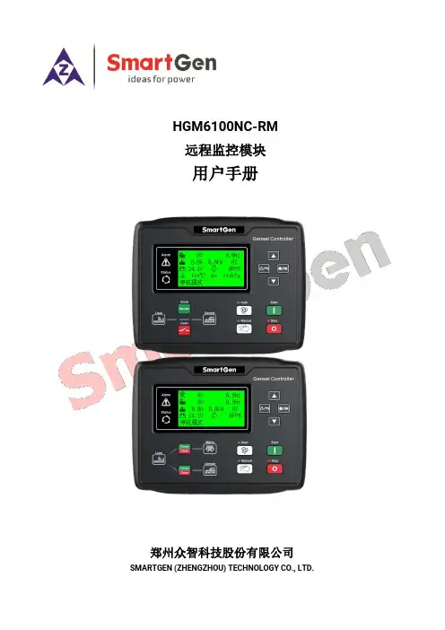
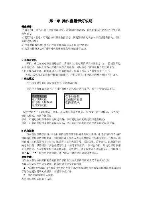
HGM6100NC-RM远程监控模块用户手册郑州众智科技股份有限公司SMARTGEN (ZHENGZHOU) TECHNOLOGY CO., LTD.目次前言 (3)1概述 (4)2性能特点 (4)3规格 (5)4操作 (6)4.1按键功能描述 (6)4.2控制器面板 (7)4.3远程控制模式操作 (8)5接线 (9)6典型应用 (11)7安装 (12)7.1卡件 (12)7.2外形及开孔尺寸 (12)8故障排除 (13)前言是众智的中文商标是众智的英文商标SmartGen ― Smart的意思是灵巧的、智能的、聪明的,Gen是generator(发电机组)的缩写,两个单词合起来的意思是让发电机组变得更加智能、更加人性化、更好的为人类服务!不经过本公司的允许,本文档的任何部分不能被复制(包括图片及图标)。
本公司保留更改本文档内容的权利,而不通知用户。
公司地址:中国·河南省郑州高新技术开发区金梭路28号电话:+86-371-67988888/67981888/67992951+86-371-67981000(外贸)传真:+86-371-67992952网址://邮箱:*****************表1 版本发展历史日期版本内容2019-08-06 1.0 开始发布2021-01-13 1.1 修改控制器型号为HGM6100NC-RM1 概述HGM6100NC-RM远程模块是HGM6100NC系列发电机组控制器的远程监控模块,通过RS485接口实现了发电机组的远程开机/停机、数据监测、报警显示等功能,用于单台远程监控系统。
模块可处于监视模式,实现只监视不控制,或通过本地模块切换为远程控制模式后,进行远程监视和控制。
HGM6100NC-RM远程模块采用微处理器技术,采用LCD为132x64的液晶显示,八种语言(简体中文、英文、西班牙文、俄文、葡萄牙、土耳其、波兰语和法语)显示,可自由切换显示。

海湾®消防设备电源监控系统产品手册重要说明:本出版物为通用版本,其中展示的产品信息仅供参考,不构成具体的承诺或者保证。
我们持之以恒地追求改进产品技术、提高产品性能,为此我们保留不经通知而对相关产品配置功能以及技术信息进行更新调整的权利。
另外,本出版物中对系统性能的描述仅适用于通常情形。
由于现实中,实地环境可能存在各种无法预知的特别情况,因此相关产品性能的实现,将有赖于专业的调查分析以及设计规划。
敬请垂询海湾公司工作人员,我们将非常乐意为您提供专业建议。
© ���� 海湾安全技术有限公司Version ������海湾安全技术有限公司服务热线:��� ��� ����地址:河北省秦皇岛开发区长江东道��号网址: 关注海湾官方微信最新资讯实时掌握便捷高效 触手可及海湾商城 码上了解“海湾服务”小程序 数字化一站式服务海湾秦皇岛工厂凭借其先进的电子产品生产线、卓越的生产管理体系、严谨的质量控制流程、科学的质量诊所管理模式,成为消防行业技术先进、精益高效的建筑智能电子产品生产基地之一,产品线覆盖从火灾前期预警到后期灭火,再到智能逃生等多个环节,其不同产品根据不同需求分别通过了CCC、UL、LPCB、CE、SAI、EAC等一项或多项国内和国际认证。
产品与服务覆盖全球多个国家和地区,向商业、工业、住宅等各行各业提供一站式消防整体解决方案。
海湾不仅为客户提供高质量的产品解决方案,同时致力于为客户提供建筑消防设施全生命周期的服务解决方案,通过海湾数字化服务平台和遍布全国100多个城市的销售服务联络网点及600多名资深技术工程师的专业团队,为客户提供专业、智能、高效的服务。
三十年来,海湾始终致力于为客户提供全面高效的一站式消防整体解决方案,提升整体生活质量,带动现代化城市发展。
海湾安全技术有限公司(以下简称“海湾”)是国内主要的火灾探测报警及消防整体解决方案提供商之一,拥有强大的技术研发与持续创新能力,丰富的消防产品组合,卓越的品牌及质量优势。

消防设备电源监控系统JBF-62S60使用说明书在安装和使用本产品前务必仔细阅读和理解该使用说明书!青鸟消防股份有限公司Jade Bird Fire Co.,Ltd.目录第一章系统概述 (1)1.1 特点 (1)1.2 参数 (2)1.3 外形尺寸 (2)1.4 结构介绍 (3)1.5指示灯及按键 (4)1.6 执行标准 (4)第二章安装调试步骤 (5)2.1 系统安装要求 (5)2.2 接线说明 (5)2.3现场调试 (5)第三章监控器主要功能 (7)第四章监控器显示说明 (8)4.1 监控器正常监视状态 (8)4.2监控器故障报警状态 (8)第五章监控器操作 (9)5.1系统查询 (10)5.1.1 查询注册地址 (10)5.1.2查询系统单元配置 (11)5.1.3 查询历史记录 (11)5.1.4 查询组网控制器 (12)5.1.5 查询注释信息 (12)5.1.6 查询传感器运行状态 (12)5.1.7 查询传感器参数: (13)5.1.8 查询电源状态 (13)5.2 测试菜单 (14)5.2.1 回路状态信息浏览 (14)5.2.2 回路电流信号浏览 (15)5.2.3 回路部件电流信号值 (15)5.2.4 现场部件类型及版本 (16)5.2.5 用户密码及授权管理 (16)5.3 设置菜单 (17)5.3.1 时间设置 (17)5.3.2 设置部件屏蔽 (17)5.3.3 设置打印机 (18)5.3.4 打印历史记录 (18)5.3.5 设置单相电压参数 (19)5.3.6 设置三相电压参数 (19)5.3.8 设置部件额定电压 (20)5.4 安装设置菜单 (21)5.4.1 回路部件自动登记 (21)5.4.2 回路部件手动登记 (22)5.4.3 设置本机地址 (22)5.4.4 定点编址 (23)5.5 系统设置菜单 (24)5.5.1 系统配置 (24)5.5.2 清除处理 (24)5.5.3 设置密码 (25)5.5.4 设置语言 (25)5.5.5 运行模式 (25)5.4.6 设置试用期 (26)5.4.7 WIFI管理 (26)5.6 帮助菜单 (27)第六章信号传感器 (28)6.1 JBF62P-ATV2A1型电压信号传感器 (28)6.1.1 功能概述 (28)6.1.2 主要功能 (28)6.1.3 主要参数 (28)6.1.4 结构尺寸 (29)6.1.5 安装与布线 (29)6.2 JBF62P-ATV1A1型电压信号传感器 (30)6.2.1 功能概述 (30)6.2.2 主要功能 (30)6.2.3 主要参数 (31)6.2.4 结构尺寸 (31)6.2.5 安装与布线 (32)6.3 JBF62P-ATV2型电压信号传感器 (32)6.3.1 功能概述 (32)6.3.2 主要功能 (33)6.3.3 主要参数 (33)6.3.4 结构尺寸 (33)6.3.5 安装与布线 (33)6.4 JBF62P-ASV6型电压信号传感器 (34)6.4.1 功能概述 (34)6.4.2 主要功能 (34)6.4.3 主要参数 (35)6.4.5 结构尺寸 (35)6.5 JBF62P-ASV1型电压信号传感器 (36)6.5.1 功能概述 (36)6.5.2 主要功能 (36)6.5.3 主要参数 (36)6.5.4 结构尺寸 (37)6.5.5 安装与布线 (37)第七章常见故障分析及维护 (39)7.1 故障处理 (39)7.2 保养维修 (39)7.3 安全使用及注意事项 (39)附录:消防设备电源监控系统的应用 (40)1、设计依据 (40)2、设计说明 (40)第一章系统概述近年来由于火灾发生时各类消防设备供电系统异常等原因不能正常投入消防灭火运行而造成重大人员、财产损失的火灾案例屡见不鲜,为了确保建筑物中的火灾报警系统、消防联动控制系统及其相关的被控设备(消防水泵、排烟风机等)在火灾发生时不会因为供电系统异常而导致这些消防设备不能投入到防灾、减灾运行的事故发生,青鸟消防股份有限公司严格遵照国标《GB 28184-2011消防设备电源监控系统》研制开发了JBF-62S60型消防设备电源监控系统。

用户操作手册尊敬的顾客感谢您购买本公司YTC5920蓄电池在线监测系统。
在您初次使用该仪器前,请您详细地阅读本使用说明书,将可帮助您熟练地使用本仪器。
我们的宗旨是不断地改进和完善公司的产品,因此您所使用的仪器可能与使用说明书有少许的差别。
如果有改动的话,我们会用附页方式告知,敬请谅解!您有不清楚之处,请与公司售后服务部联络,我们定会满足您的要求。
由于输入输出端子、测试柱等均有可能带电压,您在插拔测试线、电源插座时,会产生电火花,小心电击,避免触电危险,注意人身安全!◆慎重保证本公司生产的产品,在发货之日起三个月内,如产品出现缺陷,实行包换。
三年(包括三年)内如产品出现缺陷,实行免费维修。
三年以上如产品出现缺陷,实行有偿终身维修。
◆安全要求请阅读下列安全注意事项,以免人身伤害,并防止本产品或与其相连接的任何其它产品受到损坏。
为了避免可能发生的危险,本产品只可在规定的范围内使用。
只有合格的技术人员才可执行维修。
—防止火灾或人身伤害使用适当的电源线。
只可使用本产品专用、并且符合本产品规格的电源线。
正确地连接和断开。
当测试导线与带电端子连接时,请勿随意连接或断开测试导线。
产品接地。
本产品除通过电源线接地导线接地外,产品外壳的接地柱必须接地。
为了防止电击,接地导体必须与地面相连。
在与本产品输入或输出终端连接前,应确保本产品已正确接地。
注意所有终端的额定值。
为了防止火灾或电击危险,请注意本产品的所有额定值和标记。
在对本产品进行连接之前,请阅读本产品使用说明书,以便进一步了解有关额定值的信息。
请勿在无仪器盖板时操作。
如盖板或面板已卸下,请勿操作本产品。
使用适当的保险丝。
只可使用符合本产品规定类型和额定值的保险丝。
避免接触裸露电路和带电金属。
产品有电时,请勿触摸裸露的接点和部位。
在有可疑的故障时,请勿操作。
如怀疑本产品有损坏,请本公司维修人员进行检查,切勿继续操作。
请勿在潮湿环境下操作。
请勿在易爆环境中操作。
保持产品表面清洁和干燥。
第一章操作盘指示灯说明键盘操作:1.“消音”键(红色)用于使控制器火警、故障响声的消除,旁边的指示灯亮提示“已处于消音状态”;2.“复位”键(蓝色)可复位控制器于监控状态,恢复警报前的状态(必须解除警报先,否则复位仍然报警);3.“声光警报器启/停”键可对声光警报器输出端进行启/停控制;4.“火警传输设备启动”键可对火警传输设备输出端进行启动。
1 开机与关机开机:确认交流电源正确连接后,将机内主/备电源的开关打到上方(I),控制器即进入开机过程。
面板上各指示灯进行动态点亮检查。
同时查看“前端设备”的登录情况。
开机工作基本完成,控制器进入正常监控状态,屏幕上部显示“系统监控中···”。
关机:关机要用钥匙打开机箱才能进行,开箱后将主/备电源上的开关打向下方(O)。
2 联动模式在主机菜单里面可以设置系统手/自动模式转换。
在菜单下操作数字键“5”(用户操作)进入如下选项菜单,共有7个选项如下图。
按数字键“7”(操作模式)菜单,进入操作模式界面后。
按“F1”键手动模式,按“F2”键自动模式,按回车键保存。
手动:可通过按键和菜单启动现场设备,不可通过主机的联动程序进行联动;自动:可通过按键和菜单启动现场设备,也可通过主机的联动程序进行联动现场设备。
3 火灾报警当系统配接的探测器、手动报警按钮等报警部件确认发现火情时,通过总线将报告给控制器将报警信息传给控制器。
控制器经确认后进入火灾报警状态并发出火警声、光警报。
此时面板上红色火警指示灯常亮,液晶屏上显示火警序号、火警总数、首警部位、报警部件的编号及类型、报警时间、安装位置等信息(参见下图显示),同时打印机、历史记录记录相关火警信息。
当火警数量超过满屏显示时,除首警外,其余报警可自动循环显示,按键盘上的“▲”、“▼”键也可手动查询。
按“确认”键时单屏显示该条信息。
处理步骤:当发生火警时应根据控制器的报警信息检查发生火警的部位确认是否有火灾发生若确认为火灾发生应采取如下措施应建立火灾处理预案(1)启动报警现场的讯响器发出火警声光提示讯响器启动时控制器显示面板的警报启动指示灯点亮通知现场人员撤离,并展开扑救工作。
目录第一章系统概述 (1)第二章放电负载 (2)2.1主要特点 (2)2.2外观尺寸与接线端子 (2)2.3操作说明 (2)第三章循环放电主监控器 (3)3.1主要特点 (3)3.2 型号说明 (3)3.3 原理框图 (3)3.4外形尺寸 (4)3.5接口定义 (4)3.6操作说明 (7)第四章平面布置与接线端子 (14)4.1 平面布置 (14)4.2 接线端子 (14)附件一系统参数设置 (17)第一章系统概述电池循环充放电系统主要由整流模块(由外提供)、放电负载、蓄电池和循环放电主监控等四部分组成,见图1-1。
整流模块将交流变成直流,对电池进行充电;恒流放电负载能够保证蓄电池按恒定电流进行放电;主监控管理检测电池信息,并对电池进行循环充放电,测试电池性能。
在本说明书中,我们将详细介绍放电负载和主监控器。
系统特点✧系统采用移动式屏柜,移动方便。
✧电池接线柱为接插式,更换电池方便,插拔灵活。
✧监控采用大屏幕真彩液晶显示,触摸式图形化操作,方便用户操作。
✧实现系统全参数本地和远端监控,满足“四遥”功能及无人值守需要。
✧系统内部多串口并行通讯,确保采样数据的实时性,真正做到监控系统的实时快速监测和控制。
✧监控软件升级方式多样化,可以用U盘升级,也可以通过网络接口在线远程进行升级。
图1-1 电池循环充放电系统第二章放电负载2.1主要特点✧恒流放电装置采用PTC负载,无红热、安全可靠、使用寿命长。
✧恒流放电装置采用多个负载模块并联设计,容量配置灵活。
2.2外观尺寸与接线端子恒流放电负载外形尺寸如下所示;恒流放电负载接线端子如下所示;2.3操作说明当放电空开闭合后,电池开始以恒流放电负载设置好的电流值来进行恒流放电。
在放电过程中,当电池满足下列四项中的任意项时(1、电池单节欠压2、电池端欠压3、放电容量达到停止容量4、放电时间达到设定值),主监控器将下发停止放电的信号,断开放电开关。
恒流放电负载的电流值可以调节,一般为电池容量的10%,也可以根据用户需要调节。
BMS电池管理系统使用说明书user'sguideofBMS1.系统介绍BMS(Battery Management System)是一种用于电池管理和监控的系统,用于确保电池的安全性和性能。
本说明书将向您介绍如何正确使用BMS系统。
2.安装准备在安装BMS之前,请确保已经关闭电池电源,并且适当地接地。
检查并确保所有电缆和连接器都牢固连接。
BMS应安装在通风良好且干燥的地方。
3.硬件连接将BMS的正极连接到电池组的正极,将BMS的负极连接到电池组的负极。
确保连接稳固并紧固好螺钉。
检查所有连接以确保没有松动或接触不良。
4.功能设置通过连接到BMS的终端设备,您可以进行BMS的功能设置。
根据实际需要,您可以设置电池容量、单体电压范围、充电和放电限制等参数。
确保在设置参数之前详细阅读BMS的用户手册。
5.监测和报警BMS可以实时监测电池的状态,并且在有异常情况时发出警报。
当电压、温度或电流超出设定范围时,BMS会通过声音、灯光或终端设备上的警报通知您。
请确保及时处理警报情况以防止任何意外损害。
7.警告事项在使用BMS时,请务必注意以下事项:-严禁使用非原厂或非推荐的电池组、传感器或其他配件。
-不得擅自改动BMS系统的电路或参数设置,以避免损坏电池组或危险情况。
-不得将电池组连接到逆变器或电网上,以免造成损坏或危险。
-定期检查和保养BMS系统,确保所有连接和电缆都处于良好状态。
8.常见问题解答Q:BMS系统无法正常启动怎么办?A:检查电池组和BMS的连接是否正确并稳固,确保BMS的电源供应正常。
Q:BMS报警灯持续闪烁是什么意思?A:持续闪烁的报警灯通常表示电池组的电压、温度或电流超过了设定范围,请及时采取相应的措施。
ViewPower用户手册雷迪司(LADIS)UPS不间断电源监控系统管理软件软件系统登录密码:administrator目录1. ViewPower 概况 (2)1.1. 简介 (2)1.2. 结构 (2)1.3. 应用软件 (3)1.4. 特征 (3)2.ViewPower 的安装与卸载载 (3)2.1. 系统需求 (3)2.2. 软件安装 (4)2.3. 软件卸载。
(11)3. 服务托盘应用程序 (11)3.1. 开始监测 (12)3.2. 停止监测 (12)3.3. 配置 (12)3.3.1. 端口修改 (12)3.3.2. ViewPower启动和退出设置 (13)3.3.3. 软件升级 (13)3.3.4. 配置保存 (15)3.4. 软件升级 ................. (15)3.5. 调试方式 (16)3.6. 开放监测 (17)3.7. 留言板 (17)3.8. 退出 (18)4. ViewPower GUI界面 (18)4.1. 刷新 (19)4.2. UPS 搜索 (20)4.3. UPS 导航 (21)4.3.1. UPS 监控信息 (21)4.3.2. UPS 远程控制与监视 (22)5. ViewPower 功能菜单 (23)5.1. ViewPower 配置 (23)5.1.1. 密码配置 (23)5.1.2. 存储管理服务配置 (24)5.1.3. Email 配置 (26)5.1.4. 事件动作配置 (28)5.1.5. 局域网唤醒 (29)5.1.6. Com.Port 即插即用配置 (30)5.1.7. 数据设定 (31)5.1.8. ModBus通信设置 (31)5.2 UPS设置 (32)5.2.1.本地关机 (32)5.2.2. 远程关机 (35)5.2.3. 参数设置 (36)5.2.4. 采购信息 (38)5.3. 控制 (39)5.3.1. 实时控制 (39)5.3.2. 定时开/关 (40)5.3.3. 定时电池自我测试 (41)5.4. 视图 (42)5.4.1. 状态 (42)5.4.2. 历史记录 (45)5.5. 格式 (49)5.6. 语言 (49)5.7. 帮助 (49)附录 A: 词汇表 (51)1. ViewPower 概况1.1. 简介ViewPower是UPS的管理软件,该软件对家庭用户和企业堪称完美。
新能源重卡电池箱动力电池系统用户使用手册目录前言 (2)第一章安全使用须知 (3)第二章产品组成介绍 (4)2.1.基本组成 (4)2.2.动力电池箱 (6)2.3.BJB(PDU)与BMC (7)2.4.其余零部件 (9)第三章产品使用说明 (11)3.1.电池系统使用条件 (11)3.1.1.工作环境温度 (11)3.1.2.发车前检查 (11)3.2.电池系统安装要求 (12)3.2.1.标准电池箱的安装 (12)3.2.2.BJB(PDU)和BMC 的安装 (14)3.2.3.线缆/线束连接 (15)3.2.4.水冷管路组件的安装 (21)3.2.5.标准电池箱的拆卸 (22)第四章日常点检与保养维护 (23)4.1.日常点检要求 (23)4.2.维护保养 (26)4.2.1.保养周期 (26)4.2.2.装车电池系统全充放保养流程: (26)4.2.3.注意事项 (26)第五章常见故障与处理 (27)第六章应急预案 (28)6.1.电池运行过程中可能发生的极端异常 (28)6.2.使用过程中电池系统发生冒烟、起火时应急措施 (28)第七章存储、运输与回收 (29)7.1.电池系统的存储 (29)7.2.电池系统的运输 (29)7.3.电池系统的回收 (29)第八章系统维修常用工具 (30)前言感谢您选择公司提供的第三代标准电池箱动力电池系统(磷酸铁锂体系),我们将为您提供最优质的产品和最周到的服务。
尊敬的客户,请您详细阅读说明书后再使用本产品。
尊敬的客户,请在收到电池系统时仔细检查并确认以下内容:1.外包装箱是否完好;2.产品外观是否完好;3.装箱清单及箱内附件是否齐全;4.对于标识或提前声明为需要回收的包装材料及其它部件,在我们回收之前,请您为我们妥善保管,如损坏或丢失超过一定比例,需要收取一定费用;5.对于不需要回收的包装材料,也建议保留一段时间,以便运输或维修时使用。
尊敬的客户,电池系统进行充电时,请用双方认可的充电设备。
Link 4 Battery Monitoring SystemUser GuideTable of ContentsIntroduction (3)Navigation (4)Installing Link Software (5)Logging In For The First Time (6)Adding A New Battery Monitor System (7)Viewing All Your Batteries (8)Viewing An Individual Battery (9)Alarms (10)Graphing A Recorded Discharge (11)Analysing The Trends Of Your Batteries (12)Creating A Discharge Report (13)Link Alarm Clearing Behaviour (14)Alarm Behaviour – PowerShield Controller (14)Alarm Behaviour – Sentinel (15)Link Service Edition (16)IntroductionPart Number 6300-01715 November 2017The information contained in this manual is copyright and may not be reproduced without the written authority of PowerShield LtdPowerShield LimitedPO Box 102-190NSMCNorth Shore City 0745New ZealandNavigationLink consists of a number of pages, each providing different functionality. These pages are shown in the tool bar in the left pane, simply click an icon to select each page. Within a page there are a range of tabs, buttons and drop down selection lists, along with the battery data being displayed. In some places you will need to make a selection or enter information so Link can display the battery information you require.TIP 1: See the General Settings and Admin Utility items in the Help menu for added functions like backing up your Link database and configuring email alarm alerts.TIP 2: Some navigation & functions vary slightly between Standard Edition and Service Edition. This User Guide generally refers to behaviour of the Standard Edition. See Installing Link Software section and Link Service Edition section formore information.Installing Link SoftwareRecommended PC requirementsTo Set up Link1. Run Link Setup.exe from the CD supplied with your PowerShield system.2. Follow the installation wizard steps to match your requirements.A Full Installation should be applied for normal operations.TIP 1: If you get a User Account Control pop up screen (e.g. Windows 10/8/7 users) click Yes to continueTIP 2:If you don’t have the system CD, Link software is also available for download at . Contact PowerShield for further assistance.TIP 3:Install the Standard Edition for fixed PC’s with Link running 24/7. Install the Service Edition for laptops with temporary activity and connections. Talk to PowerShield if you need to change from one edition to anotherLogging In For The First TimeFrom the Connect menu, select Login.The default login details are:Username: adminPassword: ADMINClick Login to proceed.TIP 1: Username and password are both case sensitive. You can add additional users and set passwords from the Settings >> Users section.TIP 2: When you login, you are only logging in to the Link software utility – you are not logging in to a particular battery monitor.Adding A New Battery Monitor SystemYou need to ‘add’ your battery monitor system to Link before you can view it. Note the battery monitor needs to be configured before it can be added to Link.Each subsequent battery and battery monitoring system needs to be added to Link in the same manner.1. Go to the Settings >> Systems page.2. Click the Add button.The Add System Wizard will guide you through the steps required – simply follow the prompts.TIP 1: The battery monitor should be fully configured before it is added to Link.TIP 2: Earlier versions of Link used the terms ‘Site’ and ‘Sitename’ to identify an individual battery monitoring system. Link now uses the term ‘System’.Viewing All Your BatteriesThe Dashboard page shows the current status of all battery systems and displays all alarms that require attention. Click on the various icons for a particular system to:●view real time data for the individual batteries in a string●Hover over the string icons to view a list of alarm information for the systemTIP 1: The red Dashboard indicators show the present status with respect to any alarm limits set.TIP 2: Clicking on the indicator for a particular string will take you direct to the Real-Time >> Detail for that string. TIP 3: The Service Edition will only show systems that are currently enabledViewing An Individual BatteryThis page provides the user with the latest measurements for individual battery voltage, ohmic value and temperature. Note that Link automatically displays the parameters that the battery monitor is configured with – not all systems provide all parameters.1. Go to the Real-Time >> Detail page.2. Select the System name to view from the drop down list.3. Select the String name from the drop down list for the battery you wish to view.You may also:∙View the actual measurements (Table tab)∙Save the measurements to a report in either PDF or CSV format (Save Report)TIP 1: Link is designed for connection to multiple battery systems – remember to select the system you wish to view.TIP 2: The battery voltages are shown live and updated at the battery monitor every four seconds. Ohmic is updated once per day or as per operator settings.TIP 3: You may also access this screen directly by clicking on the green or red indicator for a particular string at the Dashboard.AlarmsThis page provides the user with details of any current alarms. See the section about Link Alarm Clearing behaviour as the alarm behaviour is different depending on battery monitor model.Clearing an alarm:1. Go to the Alarm Status page.2. (Sentinel only) Select the alarm to be cleared from the list of Active alarms in the Active tab.3. Click the Clear button.Please note you cannot clear an alarm on a PowerShield Controller as it clears them automatically. When an alarm is deactivated from the PowerShield Controller it is automatically registered as archived within Link.Note that the Link Dashboard may also generate alarms for Sentinel monitors. When the Dashboard is run, it takes each measurement and cross-checks them with their reference limits. If the measurements are outside the range of their reference limits, an alarm is sounded and is subsequently added to the list.TIP 1: More specific details for a selected alarm and its history are listed in the Details box on the right of the page.Refer to the Help tab for more detail about alarm states.TIP 2: You can also view old alarms via the History tab.Graphing A Recorded DischargeTo Graph a recorded discharge you must ensure that Link has downloaded the discharge from the battery monitor.1. Go to the Graph By >> Event page.2. Select the System name to view from the drop down list.3. Select the other parameters you wish to view – string number, battery number, measurement type – Voltage orTemperature.4. Select the event date you wish to view from the events list.5. Click Show on Graph 1.TIP 1: The discharge data set MUST be transferred from the monitor to the Link database (an automatic process at end of discharge) prior to disconnection. If you cannot find the event in the event list or are unsure, you can view and ‘force’ thi s transfer at the Data Transfer >> Downloads page if the monitor is still connected.TIP 2: You can display measurements in Graph 1 or Graph 2 so that different measurement parameters can be visually compared. For example graph all Block voltages on Graph 1 and the String Current on Graph 2.Analysing The Trends Of Your BatteriesGo to the Graph By >> Trend page.1. Select the System name to view from the drop down list.2. Select the date range you wish to analyse.3. Select the string number4. Select the other parameters you wish to view – battery number, measurement type.5. Click Add To Graph 1.TIP 1: You can also access this page by clicking on an individual battery voltage bar in the Real-Time >> Detail screen. TIP 2: You can print and save the graph by right clicking on the graph and making the desired selection.TIP 3: Click on an item graph line to highlight and determine a particular item number in the graph key.TIP 4: You can view the measurements from a particular day and time at the Graph By >> Day page.Creating A Discharge ReportThe data for all reports is derived from the battery monitor. Ensure that sufficient time is allowed for data to be transferred to the Link database before creating a report.1. Go to the Reports page.2. Click the New button to generate a new report and select Discharge from the list of Report Types.3. Select the System name you wish to report on from the drop down list on the Discharge Report page.4. Select the relevant string(s) and click Search Events5. Select the event date you wish to view from the events list.6. Click Generate the Report to proceed.TIP 1:You can generate a Discharge Report ‘offline’ without being connected to a monitor. Howe ver the discharge data set MUST have been transferred from the monitor to the Link database (an automatic process at end of discharge) prior to disconnection. If you cannot find the event in the event list or are unsure, you can view and ‘force’ this trans fer at the Data Transfer >> Downloads page if the monitor is still connected.TIP 2: The report will use the alarm limits set on the monitor, or you can adjust these when creating the report by selecting Create Custom Limits.Link Alarm Clearing BehaviourLink automatically clears battery alarms for the Sentinel to provide up-to-date battery status. This function is not required for the PowerShield Controller as it clears its own alarms.Alarm types:∙Battery alarms relate directly to the battery system and its environment∙System alarms (which are not automatically cleared) relate to proper operation of the battery monitor and must be cleared manuallyAuto-clear functions only occur within the Standard Edition on Sentinel monitors.Alarm Behaviour – PowerShield ControllerWhen an alarm is cleared by the PowerShield Controller, the alarm record in Link will automatically move into the ‘archived’ state.Alarm Behaviour – SentinelThe Link application will clear alarms from the Sentinel on an hourly schedule. If the alarm is triggered again within a period of two minutes after its initial deactivation it will once again enter ‘an active’ state. During the two minute period the alarm is in the ‘pending’ state. If it is not triggered within the two minute time frame it will enter into the ‘archived’ state.TIP 1: You can adjust the alarm clearing schedule with the Admin Utility accessible from the Help menu.Link Service EditionLink offers two different operating formats –a Standard Edition for fixed PC’s with Link running 24/7, and a Service Edition for laptops with temporary activity and connections. Some navigation and functions vary slightly between the two editions. This User Guide generally refers to behaviour of the Standard Edition – however the major functional differences are highlighted here.Link Service Edition:∙Starts in the Settings >> System page∙Only shows Enabled systems on the Dashboard∙Allows creation of multiple systems with same communication parameters∙Has automatic date & time synchronisation disabled∙Has the Dashboard poll disabled. A status update m ust be ‘forced’ by the operator∙Has no alarm auto-clearing functionality∙Has automatic memory downloads disabled for trend data. Memory downloads must be ‘forced’ by the operator, and an option is given to delete/not delete from monitor after download∙Has automatic memory downloads delayed for event data. A warning panel will appear advising that downloads will start soon∙Memory download s can be ‘forced’ by the operator, and an option is given to delete/not del ete from monitor after download∙Disables communication with all monitor systems when LinkClient is closed∙LinkServer is in sleep mode when LinkClient is not runningTIP 1: The Service Edition is recommended for service personnel making temporary connections. Full functionality is available, but automated background processes are disabled or delayed to provide best speed and prevent unwanted or conflicting actions.。