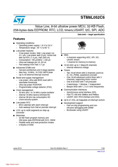
June 2012Doc ID 022924 Rev 21/52STM8L052C6Value Line, 8-bit ultralow power MCU, 32-KB Flash,256-bytes data EEPROM, RTC, LCD, timers,USART, I2C, SPI, ADCData brief target specificationFeatures■Operating conditions–Operating power supply: 1.8 V to 3.6 V –T emperature range: -40 °C to 85 °C ■Low power features– 5 low power modes: Wait, Low power run (5.1µA), Low power wait (3µA), Active-halt with full RTC (1.3µA), Halt (350nA)–Consumption: 195 µA/MHz + 440 µA –Ultra-low leakage per I/0: 50 nA –Fast wakeup from Halt: 4.7 µs■Advanced STM8 core–Harvard architecture and 3-stage pipeline –Max freq. 16 MHz, 16 CISC MIPS peak –Up to 40 external interrupt sources ■Reset and supply management–Low power, ultra-safe BOR reset with 5 selectable thresholds–Ultra low power POR/PDR–Programmable voltage detector (PVD)■Clock management–32 kHz and 1 to 16 MHz crystal oscillator –Internal 16 MHz factory-trimmed RC –Internal 38 kHz low consumption RC –Clock security system■Low power RTC–BCD calendar with alarm interrupt–Auto-wakeup from Halt w/ periodic interrupt ■LCD: up to 4x28 segments w/ step-up converter■Memories–32 KB Flash program memory and256bytes data EEPROM with ECC, RWW –Flexible write and read protection modes – 2 Kbytes of RAM■– 4 channels supporting ADC, SPI, I2C, USART , timers– 1 channel for memory-to-memory ■12-bit ADC up to 1 Msps/25 channels –Internal reference voltage■Timers–T wo 16-bit timers with 2 channels (used as IC, OC, PWM), quadrature encoder–One 16-bit advanced control timer with 3 channels, supporting motor control –One 8-bit timer with 7-bit prescaler– 2 watchdogs: 1 Window, 1 Independent –Beeper timer with 1, 2 or 4 kHz frequencies ■Communication interfaces–Synchronous serial interface (SPI)–Fast I2C 400 kHz SMBus and PMBus –USART (ISO 7816 interface and IrDA)■Up to 41 I/Os, all mappable on interrupt vectors ■Development support–Fast on-chip programming and non- intrusive debugging with SWIM –Bootloader using USARTContents STM8L052C6Contents1Introduction . . . . . . . . . . . . . . . . . . . . . . . . . . . . . . . . . . . . . . . . . . . . . . . . 62Description . . . . . . . . . . . . . . . . . . . . . . . . . . . . . . . . . . . . . . . . . . . . . . . . . 72.1Device overview . . . . . . . . . . . . . . . . . . . . . . . . . . . . . . . . . . . . . . . . . . . . . 82.2Ultra low power continuum . . . . . . . . . . . . . . . . . . . . . . . . . . . . . . . . . . . . . 93Functional overview . . . . . . . . . . . . . . . . . . . . . . . . . . . . . . . . . . . . . . . . 103.1Low power modes . . . . . . . . . . . . . . . . . . . . . . . . . . . . . . . . . . . . . . . . . . 113.2Central processing unit STM8 . . . . . . . . . . . . . . . . . . . . . . . . . . . . . . . . . 123.2.1Advanced STM8 Core . . . . . . . . . . . . . . . . . . . . . . . . . . . . . . . . . . . . . . 123.2.2Interrupt controller . . . . . . . . . . . . . . . . . . . . . . . . . . . . . . . . . . . . . . . . . 123.3Reset and supply management . . . . . . . . . . . . . . . . . . . . . . . . . . . . . . . . 133.3.1Power supply scheme . . . . . . . . . . . . . . . . . . . . . . . . . . . . . . . . . . . . . . 133.3.2Power supply supervisor . . . . . . . . . . . . . . . . . . . . . . . . . . . . . . . . . . . . 133.3.3Voltage regulator . . . . . . . . . . . . . . . . . . . . . . . . . . . . . . . . . . . . . . . . . . 133.4Clock management . . . . . . . . . . . . . . . . . . . . . . . . . . . . . . . . . . . . . . . . . 143.5Low power real-time clock . . . . . . . . . . . . . . . . . . . . . . . . . . . . . . . . . . . . 153.6LCD (Liquid crystal display) . . . . . . . . . . . . . . . . . . . . . . . . . . . . . . . . . . . 163.7Memories . . . . . . . . . . . . . . . . . . . . . . . . . . . . . . . . . . . . . . . . . . . . . . . . . 163.8DMA . . . . . . . . . . . . . . . . . . . . . . . . . . . . . . . . . . . . . . . . . . . . . . . . . . . . . 163.9Analog-to-digital converter . . . . . . . . . . . . . . . . . . . . . . . . . . . . . . . . . . . . 173.10System configuration controller and routing interface . . . . . . . . . . . . . . . 173.11Timers . . . . . . . . . . . . . . . . . . . . . . . . . . . . . . . . . . . . . . . . . . . . . . . . . . . 173.11.1TIM1 - 16-bit advanced control timer . . . . . . . . . . . . . . . . . . . . . . . . . . . 183.11.216-bit general purpose timers . . . . . . . . . . . . . . . . . . . . . . . . . . . . . . . . 183.11.38-bit basic timer . . . . . . . . . . . . . . . . . . . . . . . . . . . . . . . . . . . . . . . . . . . 183.12Watchdog timers . . . . . . . . . . . . . . . . . . . . . . . . . . . . . . . . . . . . . . . . . . . 183.12.1Window watchdog timer . . . . . . . . . . . . . . . . . . . . . . . . . . . . . . . . . . . . . 183.12.2Independent watchdog timer . . . . . . . . . . . . . . . . . . . . . . . . . . . . . . . . . 183.13Beeper . . . . . . . . . . . . . . . . . . . . . . . . . . . . . . . . . . . . . . . . . . . . . . . . . . . 193.14Communication interfaces . . . . . . . . . . . . . . . . . . . . . . . . . . . . . . . . . . . . 193.14.1SPI . . . . . . . . . . . . . . . . . . . . . . . . . . . . . . . . . . . . . . . . . . . . . . . . . . . . . 193.14.2I²C . . . . . . . . . . . . . . . . . . . . . . . . . . . . . . . . . . . . . . . . . . . . . . . . . . . . . 19 2/52Doc ID 022924 Rev 2STM8L052C6Contents3.14.3USART . . . . . . . . . . . . . . . . . . . . . . . . . . . . . . . . . . . . . . . . . . . . . . . . . . 193.15Infrared (IR) interface . . . . . . . . . . . . . . . . . . . . . . . . . . . . . . . . . . . . . . . . 203.16Development support . . . . . . . . . . . . . . . . . . . . . . . . . . . . . . . . . . . . . . . . 204Pin description . . . . . . . . . . . . . . . . . . . . . . . . . . . . . . . . . . . . . . . . . . . . 214.1System configuration options . . . . . . . . . . . . . . . . . . . . . . . . . . . . . . . . . . 265Memory and register map . . . . . . . . . . . . . . . . . . . . . . . . . . . . . . . . . . . 275.1Memory mapping . . . . . . . . . . . . . . . . . . . . . . . . . . . . . . . . . . . . . . . . . . . 275.2Register map . . . . . . . . . . . . . . . . . . . . . . . . . . . . . . . . . . . . . . . . . . . . . . 28 6Interrupt vector mapping . . . . . . . . . . . . . . . . . . . . . . . . . . . . . . . . . . . . 457Package characteristics . . . . . . . . . . . . . . . . . . . . . . . . . . . . . . . . . . . . . 477.1ECOP ACK . . . . . . . . . . . . . . . . . . . . . . . . . . . . . . . . . . . . . . . . . . . . . . . . 477.2Package mechanical data . . . . . . . . . . . . . . . . . . . . . . . . . . . . . . . . . . . . 487.2.148-pin low profile quad flat 7x7mm package (LQFP48) . . . . . . . . . . . . . 48 8Device ordering information . . . . . . . . . . . . . . . . . . . . . . . . . . . . . . . . . . 50 9Revision history . . . . . . . . . . . . . . . . . . . . . . . . . . . . . . . . . . . . . . . . . . . 51Doc ID 022924 Rev 23/52List of tables STM8L052C6 List of tablesTable 1.Medium density value line STM8L05xxx low power device features and peripheral counts 8 Table 2.Timer feature comparison. . . . . . . . . . . . . . . . . . . . . . . . . . . . . . . . . . . . . . . . . . . . . . . . . . 17 Table 3.Legend/abbreviation for Table4. . . . . . . . . . . . . . . . . . . . . . . . . . . . . . . . . . . . . . . . . . . . . 22 Table 4.Medium density value line STM8L05xxx pin description . . . . . . . . . . . . . . . . . . . . . . . . . . 22 Table 5.Flash and RAM boundary addresses. . . . . . . . . . . . . . . . . . . . . . . . . . . . . . . . . . . . . . . . . 28 Table 6.I/O port hardware register map. . . . . . . . . . . . . . . . . . . . . . . . . . . . . . . . . . . . . . . . . . . . . . 28 Table 7.General hardware register map . . . . . . . . . . . . . . . . . . . . . . . . . . . . . . . . . . . . . . . . . . . . . 29 Table 8.CPU/SWIM/debug module/interrupt controller registers. . . . . . . . . . . . . . . . . . . . . . . . . . . 43 Table 9.Interrupt mapping . . . . . . . . . . . . . . . . . . . . . . . . . . . . . . . . . . . . . . . . . . . . . . . . . . . . . . . . 45 Table 10.LQFP48 48-pin low profile quad flat package, mechanical data. . . . . . . . . . . . . . . . . . . . . 48 Table 11.Document revision history . . . . . . . . . . . . . . . . . . . . . . . . . . . . . . . . . . . . . . . . . . . . . . . . . 51 4/52Doc ID 022924 Rev 2STM8L052C6List of figures List of figuresFigure 1.Medium density value line STM8L05xxx device block diagram. . . . . . . . . . . . . . . . . . . . 10 Figure 2.Medium density value line STM8L05xxx clock tree diagram . . . . . . . . . . . . . . . . . . . . . . 15 Figure 3.STM8L052C6 48-pin LQFP48 package pinout (with LCD) . . . . . . . . . . . . . . . . . . . . . . . . 21 Figure 4.Memory map . . . . . . . . . . . . . . . . . . . . . . . . . . . . . . . . . . . . . . . . . . . . . . . . . . . . . . . . . . 27 Figure 5.LQFP48 48-pin low profile quad flat package outline. . . . . . . . . . . . . . . . . . . . . . . . . . . . . 48 Figure 6.LQFP48 recommended footprint . . . . . . . . . . . . . . . . . . . . . . . . . . . . . . . . . . . . . . . . . . . . 49 Figure 7.Medium density value line STM8L05xxx ordering information scheme . . . . . . . . . . . . . . . 50Doc ID 022924 Rev 25/52Introduction STM8L052C66/52Doc ID 022924 Rev 21 I ntroductionThis document describes the features, pinout, mechanical data and ordering information ofthe medium density value line STM8L052C6 microcontroller with 32-Kbyte Flash memory density. For further details on the whole STMicroelectronics medium density family please refer to Section 2.2: Ultra low power continuum .For detailed information on device operation and registers, refer to the reference manual (RM0031).For information on to the Flash program memory and data EEPROM, refer to the programming manual (PM0054).For information on the debug module and SWIM (single wire interface module), refer to the STM8 SWIM communication protocol and debug module user manual (UM0470).For information on the STM8 core, refer to the STM8 CPU programming manual (PM0044).Medium density value line devices provide the following benefits:●Integrated system–32 Kbytes of medium density embedded Flash program memory –256 bytes of data EEPROM – 2 Kbytes of RAM –Internal high speed and low-power low speed RC –Embedded reset ●Ultra low power consumption–195 µA/MHZ + 440 µA (consumption)–0.9 µA with LSI in Active-halt mode –Clock gated system and optimized power management –Capability to execute from RAM for Low power wait mode and low power run mode ●Advanced features–Up to 16 MIPS at 16 MHz CPU clock frequency –Direct memory access (DMA) for memory-to-memory or peripheral-to-memoryaccess● Short development cycles–Application scalability across a common family product architecture withcompatible pinout, memory map and modular peripherals –Wide choice of development tools Refer to T able 1: Medium density value line STM8L05xxx low power device features and peripheral counts and Section 3: Functional overview for an overview of the complete range of peripherals proposed in this family.Figure 1 shows the block diagram of the medium density value line STM8L05xxx family.STM8L052C6Description 2 DescriptionThe medium density value line STM8L05xxx devices are members of the STM8L ultra lowpower 8-bit family.The value line STM8L05xxx ultra low power family features the enhanced STM8 CPU coreproviding increased processing power (up to 16 MIPS at 16 MHz) while maintaining theadvantages of a CISC architecture with improved code density, a 24-bit linear addressingspace and an optimized architecture for low power operations.The family includes an integrated debug module with a hardware interface (SWIM) whichallows non-intrusive In-application debugging and ultra-fast Flash programming.Medium density value line STM8L05xxx microcontrollers feature embedded data EEPROMand low-power, low-voltage, single-supply program Flash memory.All devices offer 12-bit ADC, real-time clock, 16-bit timers, one 8-bit timer as well asstandard communication interface such as SPI, I2C, USART and 4x28-segment LCD. The4x 28-segment LCD is available on the medium density value line STM8L05xxx.The STM8L05xxx family operates from 1.8 V to 3.6 V and is available in the -40 to +85 °Ctemperature range.The modular design of the peripheral set allows the same peripherals to be found in differentST microcontroller families including 32-bit families. This makes any transition to a differentfamily very easy, and simplified even more by the use of a common set of developmenttools.All value line STM8L ultra low power products are based on the same architecture with thesame memory mapping and a coherent pinout.Doc ID 022924 Rev 27/52Description STM8L052C68/52Doc ID 022924 Rev 22.1 Device overviewTable 1.Medium density value line STM8L05xxx low power device features andperipheral countsFeaturesSTM8L052C6Flash (Kbytes)32Data EEPROM (bytes)256RAM (Kbytes)2LCD4x28Timers Basic1 (8-bit)General purpose 2(16-bit)Advanced control 1 (16-bit)CommunicationinterfacesSPI1I2C1USART 1GPIOs41(1)1.The number of GPIOs given in this table includes the NRST/PA1 pin but the application can use theNRST/PA1 pin as general purpose output only (PA1).12-bit synchronized ADC (number of channels) 1 (25)Others RTC, window watchdog, independent watchdog,16-MHz and 38-kHz internal RC,1- to 16-MHz and 32-kHz external oscillatorCPU frequency 16 MHz Operating voltage 1.8 V to 3.6 V Operating temperature -40 to +85 °C PackageLQFP48STM8L052C6DescriptionDoc ID 022924 Rev 29/522.2 Ultra low power continuumThe ultra low power value line STM8L05xxx and STM8L15xxx are fully pin-to-pin, software and feature compatible. Besides the full compatibility within the STM8L family, the devices are part of STMicroelectronics microcontrollers ultra low power strategy which also includes STM8L101xx and STM32L15xxx. The STM8L and STM32L families allow a continuum of performance, peripherals, system architecture, and features.They are all based on STMicroelectronics 0.13µm ultra-low leakage process.Note:1The STM8L05xxx is pin-to-pin compatible with STM8L101xx devices.2The STM32L family is pin-to-pin compatible with the general purpose STM32F family. Please refer to STM32L15x documentation for more information on these devices.PerformanceAll families incorporate highly energy-efficient cores with both Harvard architecture and pipelined execution: advanced STM8 core for STM8L families and ARM Cortex™-M3 core for STM32L family. In addition specific care for the design architecture has been taken to optimize the mA/DMIPS and mA/MHz ratios.This allows the ultra low power performance to range from 5 up to 33.3DMIPs.Shared peripheralsSTM8L05x, STM8L15x and STM32L15xx share identical peripherals which ensure a very easy migration from one family to another:●Analog peripheral: ADC1●Digital peripherals: RTC and some communication interfacesCommon system strategyTo offer flexibility and optimize performance, the STM8L and STM32L devices use a common architecture:●Same power supply range from 1.8 to 3.6V●Architecture optimized to reach ultra-low consumption both in low power modes and Run mode●Fast startup strategy from low power modes ●Flexible system clock●Ultra-safe reset: same reset strategy for both STM8L and STM32L including power-on reset, power-down reset, brownout reset and programmable voltage detectorFeaturesST ultra low power continuum also lies in feature compatibility:●More than 10 packages with pin count from 20 to 100 pins and size down to 3 x 3mm ●Memory density ranging from 4 to 128 KbytesFunctional overview STM8L052C610/52Doc ID 022924 Rev 23 Functional overviewFigure 1.Medium density value line STM8L05xxx device block diagram1.Legend :ADC: Analog-to-digital converter BOR: Brownout resetDMA: Direct memory accessI²C: Inter-integrated circuit multimaster interface LCD: Liquid crystal displayPOR/PDR: Power on reset / power down reset RTC: Real-time clockSPI: Serial peripheral interfaceSWIM: Single wire interface moduleUSART: Universal synchronous asynchronous receiver transmitter WWDG: Window watchdog IWDG: independent watchdog16 MHz internal RC Clock Clocks A d d r e s s , c o n t r o l a n d d a t a b u s e sDebug moduleSPI132 Kbytes Interrupt controller2 Kbytes RAMto core and peripheralsIWDG (38 kHz clock)(SWIM)Port A Port B Port C I²C1USART1PowerVOLT. REG.Port F 1-16 MHz oscillator 32 kHz oscillator 38 kHz internal RC LCD driver 4x28WWDGSTM8 Corecontroller and CSS256 bytes Port D Port E BeeperRTC memoryprogram data EEPROM @V DDV DD18V DD1 =1.8 VV SS1SWIMSCL, SDA,MOSI, MISO, SCK, NSS RX, TX, CKADC1_INxV DDA V SSASMB @V DDA /V SSA12-bit ADC1V REF+V REF-3.6 V NRSTPA[7:0]PB[7:0]PC[7:0]PD[7:0]PE[7:0]PF0BEEPALARM, CALIBSEGx, COMxPOR/PDR OSC_IN,OSC_OUT OSC32_IN,OSC32_OUTto BOR PVDPVD_INRESET DMA18-bit Timer 416-bit Timer 3 16-bit Timer 2 16-bit Timer 1 (4 channels)2 channels 2 channels3 channelsV LCD = 2.5 V 3.6 VtoLCD boosterInternal referencevoltageVREFINT outInfrared interface IR_TIM分销商库存信息: STMSTM8L052C6T6。