泛联灯控系统dll说明文档v1.0
- 格式:pdf
- 大小:196.38 KB
- 文档页数:11
本手册适用于F8L10D 系列LoRa 模块厦门四信通信科技有限公司Add:厦门市集美区软件园三期诚毅大街370号A06栋11层客户热线:400-8838-199电话:+86-592-6300320传真:+86-592-5912735网址F8L10D LoRa 模块用户硬件设计手册文档版本密级V2.0.1产品名称:F8L10D共29页文件修定记录日期版本号备注作者2016-09-14V1.0.0初始版本XQ.QIU 2017-07-04V1.1.0修改硬件设计部分参数XQ.QIU 2017-09-23V2.0.0更新地址Faine2017-11-23V2.0.1修改Uart接口RX引脚编号YSL著作权声明本文档所载的所有材料或内容受版权法的保护,所有版权由厦门四信通信科技有限公司拥有,但注明引用其他方的内容除外。
未经四信公司书面许可,任何人不得将本文档上的任何内容以任何方式进行复制、经销、翻印、连接、传送等任何商业目的的使用,但对于非商业目的的、个人使用的下载或打印(条件是不得修改,且须保留该材料中的版权说明或其他所有权的说明)除外。
商标声明Four-Faith、四信、、、均系厦门四信通信科技有限公司注册商标,未经事先书面许可,任何人不得以任何方式使用四信名称及四信的商标、标记。
目录目录 (4)前言 (5)1概述 (6)1.1技术规格 (6)1.1.1规格说明 (6)1.1.2基本功能 (6)1.1.3模块接口 (7)1.1.4LoRa参数 (7)1.1.5供电 (7)1.1.6功耗 (8)1.2相关文档 (8)1.3缩略语 (8)2F8L10D模块产品框图 (11)3管脚描述 (12)4硬件接口描述 (14)4.1概述 (14)4.2电源 (14)4.3UART接口 (15)4.3.1硬件连接 (15)4.3.2通讯传输字节格式 (16)4.3.2F8L10D通信对象为PC机 (17)4.3.2F8L10D通信对象为工控机 (17)4.4复位 (17)4.5GPIO口 (18)4.5.1控制LED灯 (19)4.5.2ADC采集参考电路 (19)4.5.3IO口保护电路 (20)4.6模块休眠 (20)4.6.1休眠控制脚SLEEP_RQ (21)4.9LoRa通过MCU对模块升级 (21)4.9.1双串口升级模式 (21)4.9.2MCU单串口升级模式 (22)4.10天线 (22)4.10.1F8L10D兼容2种天线模式: (22)4.10.2天线安装 (23)5模块硬件设计 (25)5.1硬件设计 (25)5.2模块封装尺寸 (25)5.3Re-flow回流焊温度范围 (27)订购信息 (29)前言概述本文档适用的产品是:F8L10D系列模块。
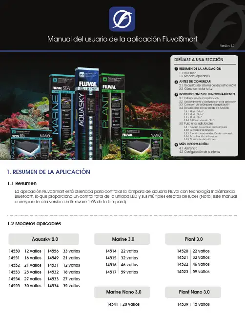
1. RESUMEN DE LA APLICACI‡N1.1 ResumenLa aplicación FluvalSmart está diseñada para controlar la lámpara de acuario Fluval con tecnología inalámbrica Bluetooth, lo que proporciona un control total de la unidad LED y sus múltiples efectos de luces (Nota: este manual corresponde a la versión de firmware 1.03 de la lámpara).1.2 Modelos aplicablesAquasky 2.014550 12 vatios 14551 16 vatios 14552 21 vatios 14553 25 vatios 14554 27 vatios 14555 30 vatios 14556 33 vatios14549 21 vatios14531 12 vatios14532 18 vatios14533 27 vatios14534 35 vatiosMarine 3.0Marine Nano 3.0Plant 3.0Plant Nano 3.014514 22 vatios14515 32 vatios14516 46 vatios14517 59 vatios14520 22 vatios14521 32 vatios14522 46 vatios14523 59 vatios14541 20 vatios14539 15 vatios2. ANTES DE COMENZARBluetooth con versión BLE 4.0 y superior Android 4.3 y superior / iOS 9.0 y superior2.1 Requisitos del sistema del dispositivo2.2 Cómo conectar la luzConecte la luz LED al transformador y, luego, conecte el transformador al tomacorriente.LUZTOMACORRIENTEAquasky 2.0Conecte la luz LED al transformador y, luego, conecte el transformador al tomacorriente.LUZPlant 3.0 y Marine 3.0TOMACORRIENTEFUENTE DE ALIMENTACIÓNPresione el interruptor táctil en la unidad de luces hasta que se encienda de color Verde . Se activará la conectividad Bluetooth.Fije la luz LED al soporte de montaje que se coloca sobre el vidrio.Plant Nano 3.0 y Marine Nano 3.02TOMACORRIENTEConecte la luz LED al transformador y, luego, conecte el transformador al tomacorriente.1En Google Play Store (usuarios Android) o App Store (usuarios iOS), busque “FluvalSmart ” e instale la aplicación gratuita.Descargue la aplicación FluvalSmartPara usuarios Android Para usuarios iOS3. INSTRUCCIONES DE FUNCIONAMIENTO3.1 Instalación de la aplicación3.2 Funcionamiento y configuración de la aplicaciónDespués de la instalación, seleccione el ícono “FluvalSmart ” para abrir la aplicación:Cuando abra la aplicación por primera vez, elija su idioma y país, y presione ”Ingresar ” paraacceder a la interfaz de la pantalla principal.FluvalSmart123.3 Conexión de la lámpara y la aplicaciónAsegúrese de que la lámpara y la conectividad Bluetooth en su dispositivo móvil estén encendidas.1Seleccione el “+” que se encuentra en la parte central o en la esquina superior derecha de la interfaz para analizar sus alrededores en busca de lámparas Fluval compatibles:24Seleccione la opción deseada de la lista de dispositivos para conectar la lámpara e ingrese la contraseña inicial “000000”. Debería ver la pantalla predeterminada de control manual:3Una vez que la lámpara deseada aparezca en pantalla, presione “Detener ” en la esquina superior derecha para finalizar el análisis. Luego, seleccione elícono “ ” junto a su lámpara y, finalmente, el ícono “√ ” de color rojo que se encuentra en la parte inferior de la página para guardar la lámpara en la lista de dispositivos:5Solo deberá ingresar la contraseña “000000” la primera vez que se conecte a la lámpara LED. Después de esto, la contraseña quedará almacenada en la aplicación y no deberá ingresarla nuevamente. Puede modificar la contraseña en el futuro.3.4 Descripción de las teclas de función3.4.1 Modo “Man”Botón de modo manual.1Ajuste de brillo: deslice hacia la IZQUIERDA o DERECHA para controlar, de forma individual, la intensidad de los canales de color.2P1, P2, P3, y P4: guarde hasta 4 espectros luminosos ingresados manualmente (después de ingresar los niveles de intensidad deseados para los colores de forma manual, mantengapresionados estos botones a fin de guardar la configuración).33.4.1.1 Plant y Marine 3.0 / Plant y Marine Nano 3.0Botón de encendido: permite encender y apagar la lámpara.41243Botón de modo manual.1Botón de encendido: permite encender y apagar la lámpara.2Botones de colores predefinidos.33.4.1.2 Aquasky 2.0Ajuste de brillo RGB+W (rojo, verde, azul y blanco). Los botones negros representan la luz blanca.4P1, P2, P3, y P4: guarde hasta 4 espectros luminosos ingresados manualmente (después de ingresar los niveles de intensidad deseados para los colores de forma manual, mantengapresionados estos botones a fin de guardar la configuración).5Botones de efectos dinámicos.6Botón de reproducción/pausa de los efectos dinámicos.72765Botón de modo automático.1Gráfico de 24 horas : representa visualmente la configuración actual.2Personalización del horario de las luces y la intensidad de los canales de color.33.4.2.1 Plant y Marine 3.0 / Plant y Marine Nano 3.0Exportar : permite al usuario exportar archivos personalizados o predefinidos que se encuentren guardados en la aplicación.4123Guardar como : permite al usuario guardar la configuración deseada.5Vista previa : permite visualizar el ciclo luminoso actual de 24 horas en menos de un minuto.6456Botón de modo automático.1Gráfico de 24 horas : representa visualmente la configuración actual.2Personalización del horario de las luces y la intensidad de los canales de color.33.4.2.2 Aquasky 2.0Exportar : permite al usuario exportar archivos personalizados o predefinidos que se encuentren guardados en la aplicación.4Guardar como : permite al usuario guardar la configuración deseada.5Vista previa : permite visualizar el ciclo luminoso actual de 24 horas en menos de un minuto.6Efectos dinámicos : permite seleccionar y programar efectos dinámicos para días de la semana y periodos específicos. Después de ejecutar un efecto dinámico, volverá al modo automático por defecto.71234567Botón de modo profesional.1Gráfico de 24 horas : representa visualmente la configuración actual.2Intervalos : permite confirmar la cantidad de intervalos distintos establecidos en el ciclo luminoso de 24 horas.33.4.3.1 Plant y Marine 3.0 / Plant y Marine Nano 3.0Exportar : permite al usuario exportar archivos personalizados o predefinidos que se encuentren guardados en la aplicación.4123Guardar como : permite al usuario guardar la configuración deseada.5Vista previa : permite visualizar el ciclo luminoso actual de 24 horas en menos de un minuto.6456Editar : permite ajustar la configuración del ciclo luminoso de 24 horas.7Vista general : permite visualizar todos los intervalos y lasintensidades de luces establecidos en el ciclo luminoso de 24 horas.878Botón de modo profesional.1Gráfico de 24 horas : representa visualmente la configuración actual.2Efectos dinámicos: permite seleccionar y programar efectos dinámicos para días de la semana y periodos específicos. Después de ejecutar un efecto dinámico, volverá al modo profesional por defecto.33.4.3.2 Aquasky 2.0Exportar : permite al usuario exportar archivos personalizados o predefinidos que se encuentren guardados en la aplicación.4123Guardar como : permite al usuario guardar la configuración deseada.5Vista previa : permite visualizar el ciclo luminoso actual de 24 horas en menos de un minuto.6456Editar : permite ajustar la configuración del ciclo luminoso de 24 horas.7Vista general : permite visualizar todos los intervalos y las intensidades de luces establecidos en el ciclo luminoso de 24 horas.8783.4.4 Editar en el Modo “Pro ” (SE REQUIERE FIRMWARE ACTUALIZADO: ver sección 3.5.4)Gráfico de 24 horas : representa visualmente la configuración actual.1Línea de intervalos establecidos.2Ajuste de brillo : deslice hacia la IZQUIERDA o DERECHA para controlar, de forma individual, la intensidad de los canales de color.3Agregar intervalo (la aplicación permite agregar hasta 10 intervalos individuales).4Eliminar intervalo (se debe establecer un mínimo de 4 intervalos en el modo “Pro ”).5Cancelar: cancela el comando de la pantalla actual y regresa a los parámetros previamente guardados.6Guardar : conserva el comando de la pantalla actual.7Seleccione “Pro ” en la interfaz de control de la lámpara para acceder al modo “Pro ”. Seleccione “Editar ” en la parte inferior de la siguiente pantalla (también puede seleccionar “X Intervalos Establecidos ”) para acceder alas funciones de edición.3.5 Funciones adicionales3.5.1 Función de escaneo de la lámparaSeleccione “Encontrar ” en la pantalla principal de interfaz de control de la lámpara para confirmar cuál es launidad de luces que está siendo controlada en el momento (esta función es particularmente útil si posee múltiples luces LED). La lámpara conectada parpadeará varias veces.3.5.2 Renombrar la lámparaPuede seleccionar la función “Renombrar ” en la esquina superior derecha de la interfaz principal de control del dispositivo para cambiar el nombre de la lámpara:3.5 Funciones adicionales (cont.)3.5.3 Función de administración de contraseñaCuando conecte la lámpara por primera vez, el sistema le solicitará que ingrese la contraseña inicial “000000”.Después de acceder a la interfaz de control del dispositivo, puede modificar la contraseña inicial con la función “Modificar contraseña”que se encuentra en la esquina superior derecha de la pantalla (Nota: la contraseñadebe tener 6 dígitos).3.5.3.1 Recuperar contraseñaSi olvidó su contraseña, siga estos pasos:En la pantalla donde debe ingresar lacontraseña, seleccione “Olvidé micontraseña”. Se mostrará una ventanaemergente.1Seleccione “Copiar” para copiar lainformación del dispositivo.2Envíe un correo electrónico a*************************,solicitandouna “Clave de recuperación” y pegue lainformación del dispositivo que habíacopiado en el paso anterior.3El equipo de soporte técnico de Fluval leenviará una clave de recuperación porcorreo electrónico que deberá pegar enel casillero de recuperación de clave,como se muestra en .Una vez que haya ingresado la clave,seleccione “Recuperar”, como se muestraen , y podrá ver su contraseña original.41563.5.4 Actualización de firmwareActualización de firmware: método unoCuando el firmware de la lámpara se pueda actualizar, aparecerá el ícono en la parte superior de lainterfaz de control del dispositivo. Seleccione este ícono para acceder a la interfaz de actualización de OTA, como se muestra a continuación.1Al acceder a la pantalla de OTA, el sistema detectará si el dispositivo se puede actualizar.2Si el dispositivo se puede actualizar, se mostrará una ventana emergente. Seleccione “Cancelar ” paraabandonar esta actualización o “Continuar ” para proceder con la actualización.3Después de confirmar la actualización, comenzará una cuenta regresiva de 20 segundos. Espere a que llegue a cero y, luego, seleccione “Siguiente ” para iniciar la actualización.4Durante el proceso de actualización, no utilice su dispositivo móvil. Espere hasta que la actualización finalice por completo antes de seleccionar el siguiente paso.5Cuando se haya actualizado con éxito, recibirá un mensaje de confirmación. Puede seleccionar “Cerrar ” para salir.6Si la actualización falló, seleccione “Presione para actualizar ” nuevamente a fin de reintentar el proceso de actualización.7123456Se requiere para tener acceso a las funciones más nuevas de su luz LED.3.5.4 Actualización de firmware (cont.)Actualización de firmware: método dosEn la página de lista de dispositivos, en la fila del dispositivo deseado, deslice hacia la izquierda. Verá las opciones “Actualizar” y “Eliminar”. Seleccione “Actualizar” para acceder a la pantalla de actualización de OTA.Siga las mismas instrucciones de actualización del método uno.3.5.5 Eliminación de la lámparaEn la página de lista de dispositivos, en la fila del dispositivo deseado, deslicehacia la izquierda. Verá las opciones “Actualizar” y “Eliminar”. Seleccione “Eliminar” para borrar la lámpara de la lista actual de dispositivos:4. MŸS INFORMACI‡N4.1 AsistenciaEn este menú, puede acceder a las funciones dePreguntas frecuentes y Solución de problemaspara obtener respuestas inmediatas a problemascomunes sobre la aplicación y su uso. Troubleshooting4.2 Configuración de la interfazLa aplicación se puede programar para encender y11 Función de cambio de idioma.2。

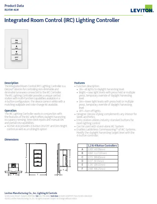
Leviton Manufacturing Co., Inc. Lighting & Controls10385 Avery Street, Tualatin, OR 97062 tel 800-736-6682 tech line (6:00AM-4:00PM PT Mon-Fri) 800-959-6004 ©2022 Leviton Manufacturing Co., Inc. All rights reserved. Subject to change without notice.DescriptionThe Integrated Room Control (IRC) Lighting Controller is a Decora ® devices for controlling non-dimmable and dimmable luminaries connected to the IRC Controller. The IRC Lighting Controller provides a unique control station with multi-function capabilities available in a 4-button configuration. The device come in white with a matching wallplate and color change kit available.OperationThe IRC Lighting Controller works in conjunction with the features of the IRC which offers daylight harvesting, occupancy sensing, time clock inputs and manual-ON and partial-ON capabilities.• RL VSW-4LW provides 4-button ON/OFF and Dim/Brightcontrol as well as a Full Bright optionIntegrated Room Control (IRC) Lighting ControllerFeatures• Function description:• ON—all lights to daylight harvesting level• Bright—raise light levels with press hold or multiple press, temporary override of daylight harvesting level• Dim—lower light levels with press hold or multiple press, temporary override of daylight harvesting level• OFF—turn off lights• Designer Decora styling complements any interior for sleek aesthetics• Entry station utilizes industry standard buttons for room lighting control• Can be used with stand-alone IRC System• Enables Ladderless Commissioning™ of IRC Systems. Modify the daylight harvesting target level with the4-button controller.1,2 & 4 Button Controllers A 1.65” (42.06mm)B4.60” (117.07mm)C 2.75” (69.85mm)D 0.37” (9.55mm)E 1.16” (29.51mm)F2.68” (68.25mm)DimensionsG-9310E/E22-aa REV JAN 2022Leviton Manufacturing Co., Inc. Lighting & Controls10385 Avery Street, Tualatin, OR 97062 tel 800-736-6682 tech line (6:00AM-4:00PM PT Mon-Fri) 800-959-6004Leviton Manufacturing Co., Inc. Global Headquarters201 North Service Road, Melville, NY 11747-3138 tel 800-323-8920 tech line (8:30AM-7:00PM ET Mon-Fri) 800-824-3005Visit our Website at: /irc©2022 Leviton Manufacturing Co., Inc. All rights reserved. Subject to change without notice.Wiring DiagramONOFF+24VDCPilotCommon*Replace x to indicate color: White (W), Ivory (I), Light Almond (T), Gray (G), Black (E) and Red (R).。
灯饰控制系统及软件操作说明书预览说明:预览图片所展示的格式为文档的源格式展示,下载源文件没有水印,内容可编辑和复制LED灯饰控制系统2010-3-16一、概述LED点光源以像素为单位,在工程上可以组成“点—线—面”各种照明实体,以及各种LED规则、异形屏等,在灯饰和户外照明方面有很大的市场前景。
在工程上,点光源以像素点为单位,具有很大的分散性,本套解决方案,主要是从点光源的特点出发,使点光源的工程施工和效果制作变得简单,灵活和方便。
1、对于异形屏,前期的灯具放置和后期的工程施工,全部在大家比较熟悉的AutoCAD 中进行。
对于规则屏,则直接在LedEdit软件里面设置即可。
2、在AutoCAD中,一个“圆”代表一个LED像素点,一条“直线”代表灯具之间的连接线,“p1,p2,p3…”代表控制系统的端口分配。
3、效果制作在LedEdit中进行,LedEdit软件直接导入或生成AutoCAD的工程布局图*.dxf文件,LedEdit软件根据AutoCAD中的灯具布局来制作效果。
如:二、异形图像处理:以QQ头像为例,介绍如何制作异形图案。
第一步,首先准备一张QQ头像的图片(用相机拍摄或通过网络下载):第二步,打开AutoCAD软件,选择“插入”菜单下的”光栅图像”,将图片插入到AutoCAD 中。
第三步,在QQ的轮廓上放置灯。
(以“AutoCAD中的“圆”代表灯”)第四步,删除“光栅图像”,开始连线和标识端口号。
第五步,在AutoCAD保存连接图,(另存为…)“QQ.dxf”。
第六步,在LedEdit软件中导入QQ.dxf文件第七步:根据“qq动画参照.bmp(制作FLASH的尺寸与其同样大小)”(该图片由LedEdit自动生成,保存在工程目录下面),在Flash软件里做动画。
生成QQ.swf参照放置图,在上层图层制作动画:制作完成后,删除放置图,并导出swf文件。
第八步:在LedEdit中播放,并记录效果。


远程控制模块使用文档本文介绍的康耐德C2000 M232-M,自带16路的开关量远程控制(继电器输出)和16路开关量采集功能,通过网络接口(TCP/IP)进行通信,可以实现通过电脑上位机对远端设备的远程控制。
C2000 M232-M是增强型金属外壳带导轨的RS232和开关量到TCP/IP的协议转换模块,它向上提供10M/100M自适应以太网接口,向下提供1个标准RS232串行口和32个开关量接点。
实现一路RS232到TCP/IP网络和TCP/IP网络到RS232的数据透明传输,同时可采集16路开关量输入(DI)与控制16路继电器开关量输出(DO),其中开关量输入状态(DI)可主动上传到上位机(调用动态库)或通过上位机使用MODBUS TCP协议查询而获取。
C2000 M232-M部集成ARP、IP、ICMP、DHCP、HTTP、MODBUS TCP等协议。
通信参数可通过软件设置,可使用动态IP或静态IP,使用时可通过软件进行设置。
特点:→具有TCP Server、TCP Client、UDP、虚拟串口、点对点连接等操作模式;→用户基于网络软件,不需要做任何修改就可以与C2000 M232-M通讯;→通过安装我们免费提供的虚拟串口软件,用户基于串口的软件不需要做任何修改就可以与C2000 M232-M通讯;→对于需要开发软件的用户,我们免费提供通讯动态库、设置动态库或OCX控件;→通过设置软件或设置动态库进行参数设置;→支持DNS域名解析功能;→远程控制和采集开关量;→开关量输入输出状态可通过本公司动态库、控件或使用标准MDOBUS TCP协议控制,方便开发或直接接入第三方软件使用;→电源具有良好的过流过压、防反接保护功能;→看门狗设计,稳定性高;→金属外壳,支持导轨安装。
a) 本产品有以下三种工作模式:1.作为TCP服务器,转换器上电后在指定的TCP 端口等待数据服务器的连接请求,数据服务器在需要与转换器通讯的时候,向转换器的监听端口请求建立TCP 连接,连接建立后,数据服务器可以随时向转换器发送数据,转换器也可以随时将数据发送到数据服务器,在完成指定的通讯后,数据服务器可以主动要求断开连接,否则连接一直保持。
LED full color lighting control systemJM4 Sub-ControllerRev. A/0User’s ManualUnited East Electronic Industrial LimitedDear valued customer,Thank you for buying UE LED full color lighting control system. The system can edit any desired program as you need, design lighting effect at will, download program promptly, run offline, transmit long distance signal (1.5m), RGB full color output control, high refresh frequency, each second can refresh maximum of 90 frames, change lighting smoothly, install easily and connect conveniently. It applies on various lighting decoration of city, scenery, road, bridge, building, entertainment area, outer door advertisement, and inside house lighting projects etc.Before you use the LED full color lighting control system, in order to operate the system properly, please read this manual carefully.UE LED full color lighting control system has applied a patent, with number 200720050043.6I.Important Safety InformationThe product uses ABS plastic outer case and flameproof PCB1. Must be far away from flammable and explosive articles2. Please use high quality of power supply, or it may cause controller to work wrongly anddamage circuit3. Be careful on waterproof protectionII.Package1、JM4 4 pixels sub-controller2、Accessories1、Master Controller2、USB cable3、Switching Power Supply4、Power Cord5、internet cable6、Light SourceIII.Sub-controller Key Functions:1、Work with main-controller JC1 as a decode output,2、4 pixels 12 line outputs (each pixel contents RGB full color output),3、Control signals connect in serial, easy to operate,。

DMX 是为简易基本应用设计的灯光控制软件这个软件为那些寻求使用简单,功能齐全而物超所值的灯光控制软件的使用者而设计的。
它的程序是很直观的,操作性强,使用起来很方便。
在独立模式下,使用者能不连电脑使用。
由于它使用简易而且价格合理,它在很广阔的范围里享有优势,因此它为很多场合的使用打开了门路。
使用者手册本手册特别为所有使用者设计了从A到 Z 的描述软件所有功能的检索。
它能回答你所有关于操作方面的问题,而且它当中的技巧和提示及快捷键将有助您更好的使用软件。
按部就班的指导将会使你能很快熟悉和发掘这个软件的用途和功能! 这个软件设计了很多提示和语言使您能不用手册也能应用。
我们愿你愉快地阅读!在这本手册中所使用的术语的解释一些字词例如场景、程序和序列常常出现在传统的控制台的技术规格或技术说明中。
这些字词的意义在这个说明书中稍有不同。
同义词对照表控台术语软件场景步程序场景序列循环包装内容• 一本多语言使用者手册• 一张软件安装光盘.• 一个连接USB接口的 DMX 512 信号转换器,带3针的信号线插口• 一条USB线个人计算机系统的最低要求• 一台带有一个空置的USB端口的手提或台式电脑。
• WINDOWS 98, ME, 2000, XP 或更高的系统.• 800x600 荧屏 (推荐用 1024x768).• 64 Mb 内存 (推荐用 256Mb).• 时钟频率: 300 百万赫兹 (推荐用 800 百万赫兹).• 8 Mb 显卡 (推荐用 64Mb).软件主要地由三个活页组成,每个活页对应一个在你编程必需的步骤,这些步骤总结如下:• 设置工作环境和设备 (设置是第 1 步)• 部分编程和创造一个现成的演出和场景 (编场景是第 2 步)• 现场的再现,修改和调试(模拟现场是第 3 步)你将会在窗户的顶端找到工具选项。
这些选项是长期可用的。
你可以达到以下功能:• 建立新的灯具 (CTRL+N)• 打开灯库里现有的灯具 (CTRL+O)• 保存当前正在建立的灯具 (CTRL+S)• 显示推杆窗口• 显示群组设置窗户• 显示三维视图• 运行声音的分析器 BPM 计算器• 运行灯库软件(Scanlibrary)建立灯库页面建立灯库页面允许配置软件和设置一场表演所需的灯光设备。
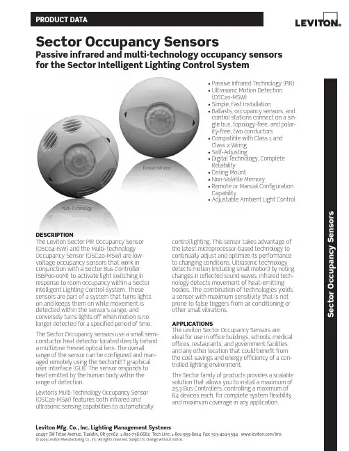
Leviton Mfg. co., Inc. Lighting Management Systems20497 SW Teton Avenue, Tualatin, OR 97062 1-800-736-6682 Tech Line: 1-800-959-6004 Fax: 503-404-5594 /lms © 2009 Leviton Manufacturing Co., Inc. All rights reserved. Subject to change without notice.S e c t o r o c c u p a n c y S e n s o r sSector occupancy Sensorspassive infrared and multi-technology occupancy sensors for the Sector Intelligent Lighting control SystemdEScrIptIoNThe Leviton Sector PIR Occupancy Sensor (OSC04-ISW) and the Multi-Technology Occupancy Sensor (OSC20-MSW) are low- voltage occupancy sensors that work in conjunction with a Sector Bus Controller (SBP00-00M) to activate light switching in response to room occupancy within a Sector Intelligent Lighting Control System. These sensors are part of a system that turns lights on and keeps them on while movement is detected within the sensor’s range, and conversely turns lights off when motion is no longer detected for a specified period of time. The Sector Occupancy sensors use a small semi-conductor heat detector located directly behind a multizone Fresnel optical lens. The overall range of the sensor can be configured and man-aged remotely using the SectorNET graphical user interface (GUI). The sensor responds to heat emitted by the human body within the range of detection.Leviton’s Multi-Technology Occupancy Sensor (OSC20-MSW) features both infrared and ultrasonic sensing capabilities to automatically control lighting. This sensor takes advantage of the latest microprocessor-based technology to continually adjust and optimize its performance to changing conditions. Ultrasonic technology detects motion (including small motion) by noting changes in reflected sound waves. Infrared tech-nology detects movement of heat-emitting bodies. The combination of technologies yields a sensor with maximum sensitivity that is not prone to false triggers from air conditioning or other small vibrations.appLIcatIoNSThe Leviton Sector Occupancy Sensors are ideal for use in office buildings, schools, medical offices, restaurants, and government facilitiesa nd any other location that could benefit from the cost savings and energy efficiency of a con-trolled lighting environment.The Sector family of products provides a scalable solution that allows you to install a maximum of 253 Bus Controllers, controlling a maximum of 64 devices each, for complete system flexibility and maximum coverage in any application.• Passive Infrared Technology (PIR)• Ultrasonic Motion Detection(OSC20-MSW)• Simple, Fast Installation• Ballasts, occupancy sensors, andcontrol stations connect on a sin-gle bus, topology-free, and polar-ity-free, two conductors• Compatible with Class 1 andClass 2 Wiring• Self-Adjusting• Digital Technology, CompleteReliability• Ceiling Mount• Non-Volatile Memory• Remote or Manual ConfigurationCapability• Adjustable Ambient Light ControlPassive Infrared Multi-Technologyproduct data FEaturES• Reduces Energy Costs: using the Sector Occupancy Sensors in a Leviton Sector Lighting Control System can reduce energy costs from 34% to 60%• Smart Settings: continuously analyze and adjust sensitivity, timer operation and long-term perfor-mance for a hassle-free lighting environment• Self-adjusting: continuously analyzing, learning and adapting to patterns of occupancy in a facility • Fast, Simple Installation: easy ceiling mount,2-wire connection (low voltage) and twist-lock sen-sor attachment• Topology-Free: ballasts, occupancy sensors, and control stations connect on a single bus, topology-free, and polarity-free, two conductors• Custom or Smart Delay-Off: manual (and self-adjusting) delay-off settings from 30 seconds to 30 minutes• Unobtrusive: small, tasteful unit blends in with any décor• Maximum Reliability, Minimum Cost: all digital circuitry uses a minimum of components• Flexible Installation: compatible with Class 1 and Class 2 wiring specifications, and Wiremold surface raceways for mounting to hard ceilings• Non-Volatile Memory: learned and adjusted settings saved in protected memory are not lost during power outages• Walk-Through Feature: increased energy savings by not leaving the lights ON for an extended period after only momentary occupancy• Ambient Light Control: includes Manual-ONand Always-ONFIELd-oF-VIEWSshown in this diagram*OCCUPANCY SENSORTo Additional Bus ControllersCan *PHOTOCELLClass 1Remote Control Circuit*SECTOR BALLASTBKG BR BR V GY RR Y BL Y BL *SECTOR BALLASTBKG BR BR V GY RR Y BL Y BL *SECTOR BALLASTBKG BR BR V GY RR Y BL Y BL *LOW VOLTAGE INTERFACE0-10V BALLAST CONTROLLERWH WH WH 24v DC Power Supply (optional)0-10V BALLASTLeviton Mfg. co., Inc. Lighting Management Systems20497 SW Teton Avenue, Tualatin, OR 97062 1-800-736-6682 Tech Line: 1-800-959-6004 Fax: 503-404-5594 /lms© 2009 Leviton Manufacturing Co., Inc. All rights reserved. Subject to change without notice.S e c t o r o c c u p a n c y S e n s o r sproduct dataG-8113A/J9-cds REV OCT 2009Leviton Manufacturing co., Inc. Lighting Management Systems20497 SW Teton Avenue, Tualatin, OR 97062Telephone: 1-800-736-6682 • F AX: 503-404-5594 • Tech Line (6:00AM-4:00PM P .S.T. Monday-Friday): 1-800-959-6004Leviton Manufacturing of canada, Ltd.165 Hymus Boulevard, Pointe Claire, Quebec H9R 1E9 • Telephone: 1-800-469-7890 • F AX: 1-800-563-1853Leviton S. de r.L. de c.V.Lago Tana 43, Mexico DF, Mexico CP 11290 • Tel. (+52) 55-5082-1040 • F AX: (+52) 5386-1797 • .mxVisit our Website at: /lms© 2009 Leviton Manufacturing Co., Inc. All rights reserved. Subject to change without notice.SpEcIFIcatIoNSElectrical• Input Voltage: 34-42VDC, 277VAC tolerant • Wires (2): Brown wires; polarity-freeEnvironmental• Operating temperature range: 32°F - 104°F (0°C - 40°C)• Relative humidity: Up to 95%, non-condensing • Usage: Indoors onlyPhysical• Size: 4.5” dia., 1.5” H (114mm, 38mm)• Weight: 5 oz. (142 g)• Housing construction: High-impact, injection molded plastic • Color: White• Leads: color coded, 6” (16.24cm)Listings• IEC61000-4-2Warranty• Limited 5-year warrantyThe following components are also part of the Leviton Sector Intelligent Lighting Control System:• Sector Ballasts (T8, 17W/25W/32W): SD1F8-17M, SD1F8-25M, SD1F8-32M, SD1J8-17M, SD1J8-25M, SD1J8-32M, SD2F8-17M, SD2F8-25M, SD2F8-32M, SD2J8-17M, SD2J8-25M, SD2J8-32M • Sector Bus Controller/Power Supply: SBP00-00M • Sector Photocell: ODC0P-0SW• Sector 5-Button Digital Switch: SDS00-15W • Sector Handheld Remote: SHH00-000• SectorNET Software and USB-to-LumaCan Adapter: SLM00-000, SIF00-000, SIFPD-000• Sector Ballast Controller: SBCS0-000, SBCS0-001• Sector 4-Module Enclosure (to hold a maximum of 4 Bus Controllers (SBP00-000)): SEN04-000。

6/11系列_泛用车床控制器操作手册匯出日期:2023-05-10修改日期:2023-01-182023/05/10, 21:041 适用机型本车床操作手册适用於新代泛用型控制器,包含:11TA、11TB、6TA、6TB。
• a.b.c.d.e.f.g.h.i.j.k.2 功能键与系统概论2.1 主画面介绍画面元件说明目前工件坐标系加工档及加工行号画面标题日期时间资料输入提示状态模式警报功能键选择2.2 功能键树状图2.2.1 八键系统2.2.2 五键系统2.3 机台座标•••••••••••••••••••路径F1机台座标 (五键、八键系列)G1加工资讯 (10+8键系列)说明针对目前机台之座标显示进行操作。
显示常用之加工资讯。
使用快速键【POS 】可快速切换至此页面。
2.3.1 画面说明座标显示本画面同时显示四组座标。
可透过「座标切换」功能,切换目前大座标的显示座标。
F(进给速率)显示使用者设定之进给速率。
显示机台的实际进给速率。
显示使用者设定之进给速率百分比。
S(主轴转速)显示使用者设定之主轴转速。
显示机台的实际主轴转速。
显示使用者设定之主轴转速百分比。
加工时间显示加工时,该加工程序已执行之时间工件数显示该加工程序已加工之次数。
搭配Pr3804的设定,程序每次执行到设定的M 码时,工件计数器会自动加一,且单件加工时间归零,当到达需求工件数後,会自动进入暂停状态。
T(刀号)显示目前加工所使用到的刀具号码及刀具补正编号。
2.3.2 座标切换路径••••••••••• a.b.i.ii.iii.•••••••• a.b.c.••••••• a.b.c.五键、八键系列:F1机台座标→F1座标切换 10+8键系列:G1加工资讯→F1座标切换说明此按键可切换目前机台画面所显示的机台座标排序。
2.3.3 1/2座标路径五键、八键系列:F1机台座标→F2 1/2座标10+8键系列:G1加工资讯→F2 1/2座标说明将相对座标的数值除以2。
条屏设置程序V2.08 DL条屏设置程序V3.01 DL条屏设置程序V4.01软件使用手册一、概述1.1 简介DL系列条屏设置程序专为DL系列脱机条屏控制卡配套设计,用于编辑更新显示内容。
DL系列控制卡支持计算机能输入的任何字体、内容,支持横向显示和纵向显示。
进入和退出均有多种花样供选择。
部分型号可分区显示时间和字幕,能满足大部分场合的需求。
和同类控制卡相比,该系列卡操作简单,控制面积大,显示花样多,显示稳定。
1.2 各种控制卡所对应的控制软件及参数请注意:各条屏设置程序软件不能通用,只能控制对应的控制卡,否则通讯不上。
1.3 DL系列控制卡特色1、专注于条屏类LED控制卡的解决方案,优化设计,简化操作,提高可靠性。
2、设计优化:相比其它条屏控制卡,控制面积大、显示稳定、工作可靠。
3、高可靠性:相比高端的大型控制卡,我们在硬件上采用了同等的接口及驱动芯片,提高了硬件的可靠性;在软件上,我们采用了较低的点频(1.5MHz)、较高的场频(100Hz),可以更稳定地刷新长条屏。
4、操作简化:直接对应最流行的接口及扫描方式,软件设置编辑简单、易用。
1.4 其他约定为方便该说明文件的描述,涉及软件名称的地方通称为“DL条屏设置程序Vx.xx”,该软件三个版本操作类似,有差异的地方会有具体的说明。
二、安装、卸载2.1 运行环境操作系统基于WIN98/WIN2000/WINXP下的集成环境;硬件配置CPU:Pentium 300MHz以上内存:64M以上2.2 安装DL条屏设置程序Vx.xx软件安装很简单,操作如下:双击“DL条屏设置程序Vx.xx Setup”安装程序,即可弹出安装界面如图2-1开始安装。
图2-1单击下一步进入选择安装路径界面,如果对此不了解使用默认安装路径即可。
图2-1-1单击下一步,进入快捷方式文件夹选项,同样保持默认即可。
图2-1-2单击下一步,进入准备安装界面,以确认安装路径和快捷方式文件夹。
目录1,系统概述--------------------------------------------------------------------------------------------------11.1 系统简介---------------------------------------------------------------------------------------------21.2 系统主要组成---------------------------------------------------------------------------------------21.3 系统硬件简要连接图------------------------------------------------------------------------------31.4 实际连线图------------------------------------------------------------------------------------------3 2,系统软件使用软件简要说明-----------------------------------------------------------------------------52.1 介绍---------------------------------------------------------------------------------------------------52.2 操作步骤---------------------------------------------------------------------------------------------52.3 取景窗口---------------------------------------------------------------------------------------------72.4 flash/cel文件的播放--------------------------------------------------------------------------------7注1:连接网络的相关设置修改--------------------------------------------------------------9注2:本机IP的查询----------------------------------------------------------------------------9注3:本机IP的修改----------------------------------------------------------------------------10注4:控制器IP的修改-------------------------------------------------------------------------11 3,对应表制作与选择-----------------------------------------------------------------------------------------123.1 介绍---------------------------------------------------------------------------------------------------123.2 操作步骤---------------------------------------------------------------------------------------------12 4,说明-----------------------------------------------------------------------------------------------------------144.1 ONC1A------------------------------------------------------------------------------------------------144.2 ONC1B------------------------------------------------------------------------------------------------144.3 ONC1C------------------------------------------------------------------------------------------------154.4 ONC1D------------------------------------------------------------------------------------------------154.5 ONC1E------------------------------------------------------------------------------------------------164.6 ONC1F------------------------------------------------------------------------------------------------174.7 ONC1G------------------------------------------------------------------------------------------------174.8 ONC1F------------------------------------------------------------------------------------------------17 5,附件-----------------------------------------------------------------------------------------------------------195.1 数码按钮控制板说明--------------------------------------------------------------------------------19 5.2 象素点排列说明--------------------------------------------------------------------------------------19版本说明:V1.0控制系统使用说明书1,系统概述: 1.1系统简介:我们的控制系统在联机控制时在电脑上提供一个可移动的取景框,LED 灯的每个像素与取景框内的点对应,同步显示;提供保存和下载功能把显示把戏下载到存储板上可脱机控制。
电子技术课程设计设计报告题目:彩灯控制电路姓名:学号:班级:计算机科学与技术1班指导教师:日期:2013.1.10摘要随着人们生活环境的不断改善和美化,在许多场合可以看到彩色霓虹灯。
用彩灯来装饰街道和城市建筑物已经成为一种时尚。
在这样的大环境下,我们需要开发出更加时尚,而且电路简单,功能更多的多路彩灯控制器,使得它能在不同的场合,不同时间段,能够有不同的闪烁频率。
通过对数字电子技术课程所学的基础理论知识的认识、了解与掌握。
本设计将采用几个基本的数字集成的74系列(74LS161,74LS151, 74LS193,555)芯片来完成所需要的数字逻辑显示功能。
设计过程中,先进行单元电路的设计,再进行总体方案的设计,通过几个方案的对比,得出最佳方案来设计总电路图。
设计的思想是以最少的芯片数量,制作成体积小、功耗低,并且具有很好的可靠性和可扩展性。
关键字计数器;数据选择器;移位寄存器目录摘要 (2)目录 (3)一、设计的任务与要求 (4)1.1 设计任务 (4)1.2设计要求 (4)二、系统设计 (6)三、方案选择与论证 (6)四、单元电路设计 (7)五实验过程与结论 (11)六心得体会 (12)七参考文献 (14)附录I:总原理图 (14)附录II:multisim仿真图 (15)附录III:元器件清单 (16)一、设计的任务与要求1.1 设计任务四路彩灯从左向右逐次渐亮,间隔为1秒。
四路彩灯从右向左逐次渐灭,间隔为1秒。
四路彩灯同时点亮,时间为0.5秒,然后同时变暗,时间为0.5秒, 反复4次课程设计作为数字电子技术课程的重要组成部分,目的是使学生进一步理解课程内容,基本掌握数字系统设计和调试的方法,增加集成电路应用知识,培养学生实际动手能力以及分析、解决问题的能力。
按照本专业培养方案要求,在学完专业基础课数字电子技术课程后,应进行课程设计,其目的是使学生更好地巩固和加深对基础知识的理解,学会设计小型数字系统的方法,独立完成系统设计及调试,增强学生理论联系实际的能力,提高学生电路分析和设计能力。
《EH300楼宇灯联网产品系列》灯联网云控制器使用说明书艾贝斯能效科技成都艾贝斯科技发展有限公司欢迎使用艾贝斯灯联产品节能云控制器说明书:本说明书介绍了该产品的多种功能、使用方法和注意事项。
使用设备前请先仔细阅读本说明书。
法律声明:版权所有©成都艾贝斯科技发展有限公司,保留一切权利。
未经成都艾贝斯科技发展有限公司书面同意,任何单位和个人不得擅自摘抄、复制本手册内容的部分或全部,并不得以任何形式传播。
本手册描述的产品中,可能包含成都艾贝斯科技发展有限公司及其可能存在的许可人享有版权的软件。
除非获得相关权利人的许可,否则任何人不能以任何形式对上述内容进行复制、分发、修改、摘录、反编译、反汇编、解密、反向工程、出租、转让、分许可等侵犯软件版权的行为。
前言能源问题己经成为全球最为关注的问题之一,能源危机已经成为全人类所面临的主要危机,特别是我国的电力能源近年来显得十分吃紧,电力紧张阻碍着我们的日常生产、生活,甚至严重影响到我国经济的发展与社会文明的进步。
在城市亮化、美化大潮的趋势下,城市照明耗电也吞噬着我们的电力资源。
节能尤为重要,随着楼宇灯联网控制系统的发展,我公司自主研发的EH300楼宇灯联网系列中的EAC——节能云控制器可以解决这一问题。
目录一、产品简介 (1)1、功能概述 (1)2、技术参数 (2)3、按键说明 (2)二、系统菜单 (3)1、系统菜单设置 (3)2、集中控制设置 (4)2-1、开关控制设置 (4)2-1-1、开关分组设置 (5)2-1-2、控制方式设置 (5)2-1-3、自动控制设置 (6)2-1-4、手动控制设置 (7)2-2、触摸面板设置 (8)2-3、人体感应设置 (8)3、系统设置 (9)3-1、系统时间设置 (9)3-2、系统地址设置 (9)3-3、系统高级设置 (9)3.4、网络参数设置 (10)3.5、远程抄表功能 (11)4、系统查询 (11)4-1、电气查询 (11)4-2、反馈查询 (12)5、电流电压参数设置说明 (12)6、WAN参数设置 (12)三、接线与安装 (13)1、接线图 (13)四、报警及维护 (14)1、电源异常 (14)2、反馈异常 (14)3、GPRS通信失败 (14)4、不按预定开关灯 (14)5、系统电流电压采集不正确 (14)6、网络通信不在线 (14)7、不能完成抄表 (14)五、注意事项 (15)六、售后服务 (15)七、法律声明 (15)八、售后服务 (16)(一)、涉及本产品的注意事项 (16)(二)、保修原则 (16)(三)、保修方法 (16)(四)、终身免费服务事项 (17)九、版本说明 (17)附件2 (18)一、产品简介1、功能概述EAC采用强大的32位嵌入式工控芯片,广泛应用于工业控制设备。
V 1.0控制(1) PW MOD IN - 接受来自另一个模块的电压以控制脉冲宽度。
(2) VCO 输出 - 通过 3.5 毫米 TS 电缆将 VCO 信号发送到一个或两个信号源。
(3) 波形图 - 为 VCO 选择脉冲, 三角或锯齿波形。
(4)脉宽 - 根据在 PW MOD IN 插孔上接收到的电压来调整脉冲宽度调制。
(5) MOD 手册 - 设置脉搏波的上部和下部之间的比率。
(6) 同步输出 - 通过 3.5 毫米 TS 电缆发送同步信号。
(7) 范围 - 以八度为单位设置 VCO 的音高范围。
(8) 同步输入 - 通过 3.5 毫米 TS 电缆接收同步信号。
(9) 弱/强 - 确定同步的准确性。
(10) 沥青 - 微调音高。
(11) MOD 等级 - 调整连接到相关 MOD IN 插孔的信号的电平。
(12) 修改输入 - 接受控制或调制 VCO间距的电压。
电源连接该模块随附所需的电源线, 用于连接到标准 Eurorack 电源系统。
请按照以下步骤将电源连接到模块。
在将模块安装到机架盒中之前, 进行这些连接会更容易。
1. 关闭电源或机架式机箱的电源, 然后断开电源线的连接。
2.将电源线上的 16 针连接器插入电源或机架盒上的插座。
该连接器具有一个卡舌, 该卡舌将与插槽中的间隙对齐, 因此不会被错误地插入。
如果电源没有键控插座, 请确保将插针 1 (-12 V) 的方向与电缆上的红色条纹对准。
3. 将 10 针连接器插入模块背面的插槽中。
连接器具有一个卡舌, 该卡舌将与插座对齐以正确定向。
4.在牢固连接电源线的两端之后, 您可以将模块安装在盒中并打开电源。
安装模块随附了必要的螺钉, 用于将其安装在 Eurorack 箱中。
安装前, 请先连接电源线。
根据机架机箱的不同, 可能会有一系列沿机箱长度方向相距 2 HP 的固定孔, 或者是一条允许单个螺纹板沿机箱长度方向滑动的导轨。
Datasheet50 mm IO-Link controlled multicolor RGB indicator with audible modelsStandard model•Bright, uniform indicator light•IO-Link control allows access to full color, flashing and dimming controls as well as advanced animations•Millions of color possibilities•30 mm threaded polycarbonate base•Translucent polycarbonate dome (standard models)•Compact models are available for lower profile applications•Rugged IEC IP66, IEC IP67, IP69K per DIN 40050-9, and UL Type 4X, 13 design •Models with integrated audible alarm available•Models constructed from FDA-grade materials availableCompact modelModelsFamily MaterialALS = Sealed Audible (IEC IP67)A1 = AudibleAL1 = Loud AudibleAudible Alarm*F = FDA-gradeQP = 150 mm (5.9 in) PVC cable with 4-pin M12/Euro-style quick disconnect ***Connector**** Audible models are not available in FDA-grade material or compact models*** Models with a quick disconnect require a mating cordsetColor & Input ** Compact models and integral quick disconnect models are not available in FDA-grade materialsWiring DiagramIO-Link ® Process Out DataIO-Link is a point-to-point communication link between a master device and a sensor and/or light. It can be used to automatically parameterize sensors or lights and to transmit and/or receive process data. For the latest IO-Link protocol and specifications,please visit . For the latest IODD files, please refer to the Banner Engineering Corp website at:.K50 Pro Indicator with IO-LinkOriginal Document 197816 Rev. D15 March 2019197816Process Data is transmitted cyclically to the IO-Link device from the IO-Link master. These parameters are written to the K50 acyclically and are used to perform the following functions:•Indicator light on and off•Audible on and off (audible models only)•Full color control of indicator light (defined colors and ability to create custom colors)•Full flashing control of indicator light (defined flashing rates and ability to create custom rates)•Full dimming control of indicator light (defined intensities and ability to create custom intensities)•Various animation control and configurability◦Flashing: flash light at defined flash rate (50/50 duty cycle)◦Two-Color Flashing: flash two colors at defined flash rate, alternating (50/50 duty cycle)◦Strobe: strobe light at defined flash rate (80/20 duty cycle)◦Half/Half: show half one color and half another color◦Half/Half Rotate: animation that shows half one color and half another color while rotating clockwise or counter-clockwise◦Chase: animation that shows a single spot in one color against a background of another color while rotating clockwise or counter-clockwise◦Demo Mode: cycles through definedcolors and then through color spectrumNote: Additional color shades can be made by adjusting intensityFor more information see IO-Link Data Reference Guide: K50 Pro Indicator (p/n 200721). SpecificationsSupply Voltage and Current24 V dc ± 25%115 mA typical at 24 V dc150 mA maximum at 18 V dcSupply Protection CircuitryProtected against reverse polarity and transient voltagesInput Response Time30 milliseconds maximum while activeAudible AlarmAll models have a steady toneA1 Model: 75 dB at 1 m (typical), 3 kHz ± 500 HzAL1 Model: 95 dB at 1 m (typical), 2.7 kHz ± 500 HzALS Model: 94 dB at 1 m (typical), 2.9 kHz ± 250 HzConnectionsIntegral 4-pin M12/Euro-style quick disconnect, or 150 mm (6 in) PVC cable with a M12/Euro-style quick disconnect, depending on modelModels with a quick disconnect require a mating cordsetMountingM30 by 1.5 threaded base, maximum torque 4.5 N·m (40 inch·lbf)Mounting nut includedConstructionStandard and Compact Model Base, Dome, and Nut: PolycarbonateFDA Model Base, Dome, and Nut: FDA-grade polycarbonateVibration and Mechanical ShockMeets IEC 60068-2-6 requirements (Vibration: 10 Hz to 55 Hz, 1.0 mmamplitude, 5 minutes sweep, 30 minutes dwell)Meets IEC 60068-2-27 requirements (Shock: 30G 11 ms duration, half sine wave)Indicator Characteristics - Tel: + 1 888 373 6767P/N 197816 Rev. DRequired Overcurrent ProtectionWARNING: Electrical connections must bemade by qualified personnel in accordance with local and national electrical codes and regulations.Overcurrent protection is required to be provided by end product application per the supplied table.Overcurrent protection may be provided with external fusing or via Current Limiting, Class 2 Power Supply.Supply wiring leads < 24 AWG shall not be spliced.For additional product support, go to .Operating Conditions–40 °C to +50 °C (–40 °F to +122 °F)90% at +50 °C maximum relative humidity (non-condensing)Storage Temperature: –40 °C to +70 °C (–40 °F to +158 °F)Environmental RatingCertifications(UL Listed applies to the dome models only.)DimensionsAll measurements are listed in millimeters [inches], unless noted otherwise.A1 and AL1 Audible ModelsM30 x 1.5ALS Audible Models(1.97")Non-Audible ModelsM30 x 1.5(mounting nutincluded)Max. Torque 4.5 Nm(40 in-lbf)Cabled ModelsCompact Models[1.97”]P/N 197816 Rev. D - Tel: + 1 888 373 67673AccessoriesCordsetsBrackets - Tel: + 1 888 373 6767P/N 197816 Rev. DSMB30SC•Swivel bracket with 30 mmmounting hole for sensor•Black reinforced thermoplastic polyester•Stainless steel mounting andswivel locking hardwareincludedHole center spacing: A=ø 50.8Hole size: A=ø 7.0, B=ø 30.0SMB30FA•Swivel bracket with tilt and panmovement for preciseadjustment•Mounting hole for 30 mm sensor•12-ga. 304 stainless steel•Easy sensor mounting toextrude rail T-slot•Metric and inch size boltavailableBolt thread: SMB30FA, A= 3/8 - 16 x 2 in; SMB30FAM10, A= M10 - 1.5 x 50 Hole size: B= ø 30.1All measurements are listed in millimeters [inches], unless noted otherwise.Banner Engineering Corp. Limited WarrantyBanner Engineering Corp. warrants its products to be free from defects in material and workmanship for one year following the date of shipment. Banner Engineering Corp. will repair or replace, free of charge, any product of its manufacture which, at the time it is returned to the factory, is found to have been defective during the warranty period. This warranty does not cover damage or liability for misuse, abuse, or the improper application or installation of the Banner product.THIS LIMITED WARRANTY IS EXCLUSIVE AND IN LIEU OF ALL OTHER WARRANTIES WHETHER EXPRESS OR IMPLIED (INCLUDING, WITHOUT LIMITATION, ANY WARRANTY OF MERCHANTABILITY OR FITNESS FOR A PARTICULAR PURPOSE), AND WHETHER ARISING UNDER COURSE OF PERFORMANCE, COURSE OF DEALING OR TRADE USAGE. This Warranty is exclusive and limited to repair or, at the discretion of Banner Engineering Corp., replacement. IN NO EVENT SHALL BANNER ENGINEERING CORP. BE LIABLE TO BUYER OR ANY OTHER PERSON OR ENTITY FOR ANY EXTRA COSTS, EXPENSES, LOSSES, LOSS OF PROFITS, OR ANY INCIDENTAL, CONSEQUENTIAL OR SPECIAL DAMAGES RESULTING FROM ANY PRODUCT DEFECT OR FROM THE USE OR INABILITY TO USE THE PRODUCT, WHETHER ARISING IN CONTRACT OR WARRANTY, STATUTE, TORT, STRICT LIABILITY, NEGLIGENCE, OR OTHERWISE.Banner Engineering Corp. reserves the right to change, modify or improve the design of the product without assuming any obligations or liabilities relating to any product previously manufactured by Banner Engineering Corp. Any misuse, abuse, or improper application or installation of this product or use of the product for personal protection applications when the product is identified as not intended for such purposes will void the product warranty. Any modifications to this product without prior express approval by Banner Engineering Corp will void the product warranties. All specifications published in this document are subject to change; Banner reserves the right to modify product specifications or update documentation at any time. Specifications and product information in English supersede that which is provided in any other language. For the most recent version of any documentation, refer to: .For patent information, see /patents.FCC Part 15 and CAN ICES-3 (B)/NMB-3(B)This device complies with part 15 of the FCC Rules and CAN ICES-3 (B)/NMB-3(B). Operation is subject to the following two conditions:1.This device may not cause harmful interference, and2.This device must accept any interference received, including interference that may cause undesired operation.This equipment has been tested and found to comply with the limits for a Class B digital device, pursuant to part 15 of the FCC Rules and CAN ICES-3 (B)/NMB-3(B). These limits are designed to provide reasonable protection against harmful interference in a residential installation. This equipment generates, uses and can radiate radio frequency energy and, if not installed and used in accordance with the instructions, may cause harmful interference to radio communications. However, there is no guarantee that interference will not occur in a particular installation. If this equipment does cause harmful interference to radio or television reception, which can be determined by turning the equipment off and on, the user is encouraged to try to correct the interference by one or more of the following measures:•Reorient or relocate the receiving antenna.•Increase the separation between the equipment and receiver.•Connect the equipment into an outlet on a circuit different from that to which the receiver is connected.•Consult the manufacturer.© Banner Engineering Corp. All rights reserved。