蓝牙音频模块说明文档V1.3(5V)
- 格式:docx
- 大小:348.76 KB
- 文档页数:3
HC-09蓝牙串口通信模块用户手册V1.3地址:广州市天河区科韵路天河软件园建工路19号608室广州汇承信息科技有限公司邮编:510665电话:************网址:软件版本:HC-09V1.3硬件版本:V1.0发布日期2020年04月29日修改记录1.增加“A T+LED”指令。
(2020.04.29)2.修正IBEACON功能。
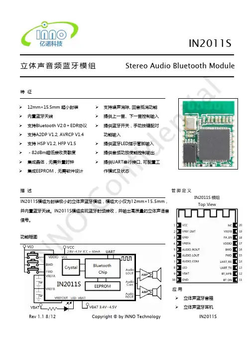
(2020.05.12)HC-09蓝牙串口通信模块是新一代的基于Bluetooth Specification BLE蓝牙协议的数传模块。
无线工作频段为2.4GHz ISM,调制方式是GFSK。
模块最大发射功率为0dBm,接收灵敏度-93dBm,空旷环境下和iphone4s可以实现50米超远距离通信。
模块采用邮票孔封装方式,可贴片焊接,模块大小18.5mm×13mm×2.2mm,很方便客户嵌入应用系统之内。
模块采用TI的CC2541芯片,配置256K Byte空间,支持AT指令,用户可根据需要更改角色(主、从模式)以及串口波特率、设备名称等参数,使用灵活。
产品尺寸管脚定义HC-09模块适用于贴片焊接,共有16个引脚,板载PCB天线,引脚具体定义如下表:引脚定义I/O方向说明1GND模块公共地2VCC输入电源脚,要求直流3.3V电源,供电电流不小于100mA 3TXD输出UART输出口,3.3V TTL电平4RXD输入,弱上拉UART输入口,3.3V TTL电平5DC输入仿真、烧录时钟脚,请悬空6DD输入/输出仿真、烧录数据脚,请悬空7SCL悬空8SDA悬空9P1.1输出模块连线指示,连线前为高电平,连线后输出低电平。
10P1.0悬空11P0.7输出模块指示灯输出脚(注①)12P0.6输入,弱上拉主机清除记忆,连线状态下会主动断线(注②)13P0.5悬空14P0.3悬空15P0.2悬空16RST输入,弱上拉模块复位脚,要求不小于10ms的低电平进行复位注①:模块指示灯输出脚,高电平输出,接LED时请串接电阻。
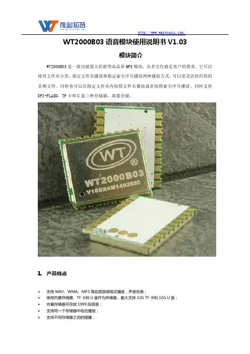
广州唯创电子有限公司MP3录音模块音频蓝牙模块目录1.产品概述 (2)2.产品应用领域 (2)3.模块特点 (2)4.功能框图简介 (3)5.管脚介绍 (3)6.模块尺寸图 (5)7.模块功能详解 (5)7.1.MP3功能部分简介 (5)7.1.1.TF卡座连接电路 (6)B连接电路 (6)7.1.3.按键电路 (7)7.2.蓝牙部分 (8)7.3.红外线遥控部分 (8)8.相关参数 (9)8.1.音频播放参数 (9)8.2.蓝牙射频特性 (9)8.3.电气参数 (10)9.版本信息 (10)音频蓝牙模块1.产品概述音频蓝牙模块是深圳唯创知音电子自主研发的智能型无线音频数据传输加上MP3音频播放产品,是低成本高效率的立体声无线传输方案,具有集成度高,体积小,低功耗,传输速度快等特点,只需在模块外围加上少许的元器件就可以实现高品质立体声音频的无线接收。
模块本身采用免驱动方式,客户只需要把模块接入应用产品,就可以快捷的实现音乐无线传输,享受蓝牙模块的乐趣。
模块本身主要具备三大功能特点、自身MP3功能(可以外挂TF卡、U盘)、手机蓝牙通讯、红外线遥控。
2.产品应用领域该模块主要用于短距离的音乐传输,可以方便地和笔记本电脑,手机,PDA等数码产品的蓝牙设备相连,实现音乐的无线传输。
●蓝牙音响●蓝牙立体声耳机●免提电话●蓝牙无线传输音频●车载音响系统●车载免提●便捷式导航设备3.模块特点1)支持MP3LayerI II III,WA V(PCM,IMA-ADPCM)格式文件的播放;2)支持SD/MMC/TF卡和各种U盘;3)支持FA T12/FAT16/FA T32/EXFAT文件系统;4)支持快进,快退,断点记忆,AB复读,EQ功能;5)支持双设备同时在线功能;6)支持MIC录音功能;7)支持蓝牙音乐播放和通话功能;8)支持LED 数码管显示屏;9)支持USB DEVICE ,包括USB HID ,USB MIC ,USB 音箱,USB 读卡器;10)支持扩音器混响功能;11)支持红外遥控功能;12)采用Bluetooth 2.1+EDR 规范,兼容蓝牙3.0及以下版本;13)支持离线升级程序。
BLE SPS Module User Manual V1.12014.6Revision HistoryCatalog1Overview (4)2Module Package (6)3Factory settings (6)4Data transmit and Command Set (7)5The format of command setting (8)5.1Switch to the Slave(Peripheral) role (8)5.2Switch to the Master(Central)role (8)5.3Modify the baud rate (8)5.4Set the address of the target module (8)5.5Set the advertising interval value (9)5.6Set connection parameters (9)5.7Set the module name (10)6View Parameters command (10)6.1View Current role of module (10)6.2View the Baud Rate of Module (10)6.3View the target module BT address (11)6.4View the BT address of the module (11)6.5View the name of module (11)6.6View the advertising interval value of module (11)6.7View the connection parameters. (11)7Program Example (12)8Test Tool (12)8.1PC software test tool (12)8.1Test the Data Passthrough Between module and module. (16)8.2Test Data Passthrough in Smartphone (17)8.2.1Use “LightBlue” APP for Testing (17)8.2.2Use the APP testing that WeBee provide(ios7.0 above) (25)1OverviewDescription:The BLE module is designed with TI CC2540/CC2541 that is a Bluetooth low energy chip which is compliant Bluetooth 4.0 single-mode. It is mainly used in low-power sensor networks and short-range wireless communication. The basic function of WB-BLE-001 is to transmit data between WB-BLE-001 module and WB-BLE-001 module or WB-BLE-001 module and smart phone.WB-BLE-001 integrate s with the “AT” command set. So the module can set in master role or slave role, the name of the module can be modified, the baud rate, advertising interval value and the connection parameters can be modified by users. Feature:Small size2.2*1.5 cmLong communication distance Smart phone to Module:60meters;Module to Module :100meters(In open environment)Optimize the BLE stack in depth,Works Power Consumption:60 ~ 800uA;Master and slave can be switchA serial port for sending interval <10msRespond time from sleep less than 0.4STransmit speed 3~5Kb/sIntegrate AT command setSupport Android 4.3 、IOS、PCNo need MFIWeBee Provide:PC software for Modify and view the relate parametersAPP Test SoftwareProfessional technical guidanceSupport enterprise, individual additional customization2Module PackageFigure 2.1 Module Package 3Factory settings4Data transmit and Command SetThe pin that the module used are as follow:When the pin P0_0 pull up as high level and at this time the pin P0_1 also pull up as high level, then the module works in transmit data mode.When the pin P0_0 pull up as high level and at this time the pin P0_1 pull down as low level, then the module works in command setting mode.When both P0_0 and P0_1 are pulled down as low level, then the module works in sleep mode.Note:1.Pin P0_0 can be connected to a pull-up resistor to 3.3V, if the Users don’t needthe sleep mode.2.Pin P0_1 can be connected to a pull-up resistor to3.3v, if the Users don’t needthe command setting mode.3.WeBee can help custom to modify the firmware for the special application.5The format of command settingAll the command format is consist of ”FA+type+data length+data+AA”, the head of the command frame is FA, type is the command type, data length is the length of user data in this frame, AA is the finish symbol of the command frame.5.1Switch to the Slave(Peripheral) roleThe default role of module is slave role. As slave role, it can communication with the smart phone and also the master role module.The command is: FA 00 00 AAIf executed successful, the module will return “Set Peripheral Role OK\n”immediately. Otherwise it means it set failed.5.2Switch to the Master(Central)roleAs the master role, the module only communicates with the slave module.The command is: FA 01 00 AAIf executed successful, the module will return “Set Central role OK\n” immediately. Otherwise it means it set failed.5.3Modify the baud rateThe module can compatible with a variety of baud rate.Otherwise it means it set failed.5.4Set the address of the target moduleWhen the module is in master role, it is need to set the master module connectwhich slave module.The command is: FA 03 06 XX XX XX XX XX XX AA;“XX XX XX XX XX XX” This 6 bytes is the target slave module address.If executed successful, the module will return "Set target address ok\n" immediately. Otherwise it means it set failed.Note: When the target slave module address is set as “00 00 00 00 00 00”, it means the master will connect the target slave module which the master first scanned. The factory setting is the “00 00 00 00 00 00”.5.5Set the advertising interval valueWhen the module is slave role, it may need to set the advertising interval value.The command is: FA 04 length interval AAFor example if want to set advertising interval value in 500ms, so the 500/0.625=800. Then turns the 800 into Hexadecimal: 800(d) = 320(h)Then 320 is the 03 and 20, so the Command is FA 04 02 03 20 AA.If executed successful, the module will return "Set Advertising interval OK\n" immediately. Otherwise it means it set failed.5.6Set connection parametersThe connection parameters influence the data transmit speed and the power consumption.The command is: FA 05 08 conn_min conn_max latency timeout AAThere are 4 variables, every variable is 2 bytes.For example if the conn_min set as 6,conn_max set as 150latency set as 0timeout set as 300Then the final command is : FA 05 08 00 06 00 96 00 00 01 2C AAIf executed successful, the module will return "Set Connection Interval OK\n" immediately. Otherwise it means it set failed.Note: The small of the connection interval, the speed is faster and the power consumption is higher.conn_min and conn_max (In 1.25 ms unit, range: 7.5 ms to 4 s (0x0006 - 0x0C80)) Latency (Range 0-499)Timeout (In 10ms unit,Range: 100ms to 32 seconds (0x000a - 0x0c80).)5.7Set the module nameWhen the module in slave role, use the following command can set the advertising name.Command: FA 06 name_length name AAFor example the name of module is set in ”123”,then the command is FA 06 03 31 32 33 AAIf executed successful, the module will return "Set Name OK\n"immediately. Otherwise it means it set failed.Note: The length of module name less than 21 bytes.6View Parameters commandWB-BLE-001 module provides the interface to view the module parameters. The current role of the module, baud rate of the module, advertising interval value of module, connection interval value of module and the name of the module can be viewed.The view command format is: ”FB+type+00+AA”6.1View Current role of moduleView the current role of the module, the command is following:FB 00 00 AAIf executed successful, the UART of the module will return as follow:When module is Peripheral role: print “ Peripheral Role”When module is Central role: print “Central Role”.6.2V iew the Baud Rate of ModuleView the Baud Rate of the module, the follow command is provided: FB 01 00 AAIf executed successful, the UART of module will print: "Baudrate is: 9600", that meas the baud rate of module is 9600bps.6.3View the target module BT addressWhen the module is in central role, it can be view the BT address of target module that the central module will connect. The command is as follow:FB 02 00 AAIf execute successful, the UART of module will print:Target Address:xxxxxxxxxxxx,xxxxxxxxxxxx is the target peripheral BT address.6.4View the BT address of the moduleEvery module has itself BT address, the following command can get the local module BT address:FB 03 00 AAIf execute successful, the UART of module will print: Local Address:xxxxxxxxxxxx6.5View the name of moduleThe name of module can be got by smart phone when the module is in peripheral role. Also can be got by UART. The following command can get:FB 04 00 AAthe UART of module will print the name of the modle.6.6View the advertising interval value of moduleUsing the following command can get the advertising interval value of module:FB 05 00 AA,If execute successful, the UART of module will print the advertising interval value. 6.7View the connection parameters.The following command can get the connection parameters:FB 06 00 AAIf execute successful, the UART of module will print the connection parameters.7Program ExampleThe external MCU sends the data to the module, the external MCU firstly must pull up the P0_0 pin the module in order in wake up the module. When finish sending data, the external MCU must bt pull down the P0_0 pin of the module.Void sendDataViaBt(unint8 *buf,uint8 len){P0_0=1 //Wake ukDelay_10us();Uart_send(buf,len);Delay_1ms();P0_0=0; //Make the module into sleep for saving power}8Test Tool8.1PC software test tool1.After installed the PC BLE software, the following picture will show.2.C lick the “Serial Configure” and input the baud rate value3.Click the “OK” to open the UART of PC.4.Here provide “View the module role” for example. Other test, the users can do byyourself.From the Part4, If send the command to the module must Pull Down the P1_0 pin. If uses WeBee Board, Pressed the S2 Key and click the “Module role” in the “View Command set”.It shows the current role is “Central”N ote: Users can do this by “UART Assistant” software without WeBee software.8.1Test the Data Passthrough Between module and module. Power on the module, When the LED1 is on that means this 2 modules is connected.Then open the “UART Assistant” software and set the UART number and baud rate. Then this to module can transmit data to each other.8.2Test Data Passthrough in SmartphoneThe smartphone can only communication with the Peripheral role module.8.2.1Use “LightBlue” APP for Testing.1.Download the ”LightBlue” app in apple app store and install it.2.Module connects to the PC via USB and Power on it. At this time, the lightbluewill found the “BLE SPS” the listed it. As the following shows.3.Click the “BLE SPS”, the smart phone will connect to the module and the LED1 ofthe board will be on. The following picture means the connection is built.4.Click “ 0xFEE0”, it will show“0xFEE1” and click “0xFEE1”,it will show the followingpicture:5.Click “Write” will send the data from smartphone to module.6.T he module gets the data from the smartphone will show in “UART Assistant”software.7.Now make the module sends data to smartphone:C lick “start notify” in the following picture.8.PC software S ends “123” to Module via UART9.T he smartphone will get the data “123” from the module. It shows as following:8.2.2Use the APP testing that WeBee provide(ios7.0 above) 10.Download the ”BLE SPS” app in apple app store and install it.1.Connect the module to PC via USB. Click “Scan Ble Device”b2.The app will list the device, when it has scan the BLE Module, Device name is:“BLE SPS”, Choose “BLE SPS” to be connected.3.After the connection is built, they can transmit data to each other.。
语音模块使用说明书V1.1(型号:YL07)秦皇岛千目电子有限公司电话:************/3250825传真:************地址:河北省秦皇岛市海港区和平大街和平E站1.产品特性 (3)2.产品图片、接口介绍及典型应用示意图 (4)42.1产品外形和接口图片..................................................................................................................................................................................................................442.2接口介绍..........................................................................................................................................................................................................................................................442.2.1左侧8P 蓝色端子........................................................................................................................................................................................................442.2.2右侧4P 蓝色端子........................................................................................................................................................................................................442.2.3 3.5音频输出..................................................................................................................................................................................................................442.2.4右侧2P 蓝色端子.. (4)42.3产品尺寸图 (4)42.4七路按键控制放音接线示意图..................................................................................................................................................................................553.语音录制过程................................................................................................................................................................................................................................................................553.1准备音频文件..........................................................................................................................................................................................................................................553.1.1打开一个任意格式音频文件....................................................................................................................................................................663.1.2另存文件 (6)63.1.3选择另存格式 (6)63.2音频文件存储到指定目录..................................................................................................................................................................................................773.3连接好硬件设备..................................................................................................................................................................................................................................773.4软件录音..........................................................................................................................................................................................................................................................883.4.1连接设备....................................................................................................................................................................................................................................883.4.2连续录音..................................................................................................................................................................................................................................883.4.3放音测试 (9)93.5软件设置参数 (9)93.5.1设置485的波特率和设备ID ID (9)93.5.2设置触点信号采集方式..................................................................................................................................................................................994.放音应用............................................................................................................................................................................................................................................................................10104.1触点触发方式......................................................................................................................................................................................................................................10104.1.1闭合播放一次..............................................................................................................................................................................................................10104.1.2闭合循环播放.. (10)104.1.3断开播放一次 (10)104.1.4断开循环播放................................................................................................................................................................................................................10104.1.5触点变化播放................................................................................................................................................................................................................10104.1.6矩阵键盘.. (10)104.2RS485通讯触发方式 (11)4.2.1RS485连接控制示意图........................................................................................114.2.2通讯协议 (11)5.性能参数 (11)6.1注意事项 (11)6.1.1音频输出接口.......................................................................................................116.1.2 3.5音频输出接口.. (11)6.2常见问题......................................................................................................................................................................................................................................................12126.2.1录音是软件连接不上.. (12)126.2.2录音软件按钮不可用 (12)126.2.3RS485转换器导致软件连接不正常........................................................................................................................................12127.技术支持及联系方式 (12)12语音模块使用说明书(型号:YL07)YL07语音模块是基于YS07型语音模块改版型号。

蓝牙音频模块说明文档V1.3(5V)蓝牙音频模块说明文档(5V)一、外观实际产品,已经焊接了插针,默认为90度弯针二、端口说明:1、+5V 电源:接电源正极,电压范围4.2V~5V ,请确保供电在此范围内,超这个范围可能损坏模块,或者导致工作不正常;2、地:GDN 接电源负极,也是音频的地,此地必需分开两根地线分别接电源地跟音频地;3、左声道:接功放板左声道输入,或者耳机的左声道,建议在该输出端口接入一个电容(视功放所匹配的输入而定);4、右声道:接功放板右声道输入,或者耳机的右声道,建议在该输出端口接入一个电容(视功放所匹配的输入而定);5、静音输出端口:该端口预置为高电平,当静音时该端口输出低电平;6、状态指示灯:当蓝牙未连接时,该灯快闪,一旦蓝牙连接成功则变为慢闪;7、预留端口:该端口已经上拉到5V ,当该端口给一个低电平触发后关机,当再次给该端口一个低电平复开机。
系统典型接线图:注意:从蓝牙音频模块到电源或者到音频接口,请采用焊接的方式,不要采用插线的方式,接触电阻比较大会引入噪声。
三、使用注意事项:1、供电电源:蓝牙音频模块属于对高频干扰敏感的电路,建议采用线性稳压电源,若采用DC-DC供电时,请加入LC滤波,降低电源谐波干扰,尤其采用手机充电器等开关电源,电源纹波可能致使蓝牙不能正常连接,而且这类的5V输出,往往在5.1V~5.4V之间,超过了蓝牙音频模块的工作电压;当采用手机适配器等开关电源工作时,请加这个供电电路,电感可不加。
2、接地:由于音频信号对于接地点引起的干扰比较敏感,可以在蓝牙模块的输出插针上面焊两根地结,一根接到电源的负极(GND),另外一根接到功放板的音频输入地,尽量焊在线路板上,不要采用引线接连(容易受干扰),并且建议可以多试一下那个接地点干扰最小;3、天线干扰:蓝牙天线极其容易受到高频,或者强电磁信号干扰,相对来说尽量远离功放板的强信号的地方,并且天线不能紧挨着金属物品,保持一定的距离;4、外壳屏蔽:由于金属外壳的机壳对于蓝牙信号有屏蔽作用,可能衰减蓝牙信号致使接收不良,请保持在有相应的开孔,或者外露。

ContentsIntroductionAbout your SoundLink® Color Bluetooth® speaker (6)Features (6)Unpacking (7)OperationConnecting to AC power (8)Charging the battery (8)Battery indicator (9)Selecting a language for voice prompts (9)Turning voice prompts off/on (9)Changing the language (9)Pairing the first mobile device (10)Playing music (10)Using the speaker with multiple devices (11)Pairing another device (11)Managing multiple connections (11)Scrolling through other paired devices (11)Clearing the speaker memory (11)Speaker controls (12)System status indicators (13)Connecting an AUX device (13)Operating on battery power (14)Checking the battery (14)Battery protection mode (14)Auto off feature (14)Tips on placing the speaker (14)4 - EnglishContents Care and MaintenanceTroubleshooting (15)Factory reset (16)Cleaning (16)Contacting Customer Service (16)Limited Warranty (16)Technical Information (17)English - 5IntroductionAbout your SoundLink® Color Bluetooth®speakerYour music keeps you moving. And with the SoundLink® Color Bluetooth® speaker, now it can move with you.Features• Inspired audio performance, anywhere you go.• Connects wirelessly to your smartphone, tablet or other Bluetooth enabled devices – up to two at a time.• Voice prompts talk you through Bluetooth pairing so it’s easier than ever.• Available in a selection of colors.• Designed and tested to support an active, mobile lifestyle.• Lithium-ion battery allows up to eight hours of unplugged play time.• Charges with most USB power sources.6 - EnglishCare and Maintenance Technical InformationTemperature range32°-113°F (0°-45°C)Operating timeUp to 8 hoursBluetooth range33 feet (10 m)Power supply ratingInput: 100 - 240VAC , 50-60Hz, 0.18AOutput: 5VDC, 1.0AInput power ratingInput: 5VDC, 1.0A MaxDimensions5.3" H x 5" W x 2.1" D (13.5 cm x 12.7 cm x 5.4 cm)Weight1.16 lb (0.53 kg)English - 17。

一、简介蓝牙发射芯片KT1025A支持的音源如下:蓝牙发射支持的音源原理1、支持发射AUX的音频这个是先采样为数字信号,转成SBC蓝牙发出去2、支持发射U盘TF卡或者spiflash的音频这个是数字信号直接转换为SBC蓝牙发出去3、支持发射PC声卡的音源这个是数字信号直接转换为SBC蓝牙发出去备注:支持是芯片支持,但是受限于软件,可能些许功能是不能同时使用的,后面详细说明二、简单操作说明1.1芯片上电返回的信息芯片上电会主动的返回一些信息,具体的查找手册,可以不用关注1.2蓝牙连接---随机搜索---最简单的使用方式1、如果是简单的应用,直接让芯片进入随机搜索就可以,他会直接进入搜索状态,搜索到谁就连谁2、芯片上电,如果是发射模式,芯片会自动进入空闲,等待用户发送指令1.3蓝牙连接---指定地址去连接---比较复杂1、这个详细的可以看看手册2、简单来说,就是先搜索周围的设备,获取名字和MAC地址,然后再指定MAC地址去连接1.4蓝牙发射的音源说明1、优先级:U盘>TF>flash>AUX>PC2、如果连接成功之后,会依次按照如上的顺序去初始化设备,然后播放音乐,同时发射音源1.5蓝牙发射的一些内部操作说明1、蓝牙在发射状态,他的搜索流程是,简单来讲就是如下的方式:(1)、芯片接收到相对应的指令之后,会主动发起搜索,同时会自动开始计时。
时间限定为6秒钟左右(2)、芯片在搜索的过程中,会不断的发现周边的设备,和你手机其实是一样方式,只是没有显示屏而已(3)、如果设定的时间到了,蓝牙芯片就超时了:==>如果芯片是随机搜索,那么即使超时了,他也会再次发起搜索并连接==>如果是芯片只是为了查找周边的设备,那么他超时就停止了==>如果他是指定MAC地址去连接,那么他超时之后,也会继续发起搜索并连接(4)、同时发起搜索,搜索停止等等状态,都是可以通过指示灯或者串口查看的,详细的请查阅手册1.6测试注意事项1、重点关注指示灯的状态:常亮、慢闪、超快闪2、常亮代表连接成功,超快闪就代表搜索中,慢闪基本就是空闲。
Bluetooth Module DatasheetModel:SJR-BTM308-CVersion:V1.12018-07-05Sky Jiarun Technologies Co.,Ltd.Tel:(0755)85279490E-mail:sales@Web:Fuyong,Baoan,ShenzhenList of Contents1Introduction (3)2Key Features (3)3Applications (4)4Block Diagram (4)5General specifications (4)6Module Package Information (5)6.1Pinout Diagram and package dimensions (5)6.2Module Pin descriptions (6)7Electrical Characteristics (9)7.1Absolute Maximum Ratings (9)7.2Recommended Operating Conditions (9)8Recommended reflow temperature profile (10)1IntroductionSky Jiarun Technologies introduces the pioneer of the Bluetooth5.0modules SJR-BTM308-C which is a high performance,cost effective,low powerand compact solution.The Bluetooth module provides a complete2.4GHzBluetooth system based on the QCC3008QFN chipset which is a singlechip radio and baseband IC for Bluetooth2.4GHz systems,.This module is fullyqualified single-chip dual mode Bluetooth@v5.0system.2Key FeaturesBluetooth Profiles●Bluetooth v5.0specification support●Qualcomm®Bluetooth®Low Energy secure connection●A2DP v1.3.1●AVRCP v1.6●HFP v1.7●HSP v1.2●SPP v1.2●DID v1.3●HOGP v1.0●PXP v1.0.1●FMP v1.0●BAS v1.0●QTIL's proximity pairing and QTIL's proximity connectionMusic Enhancements●aptX,aptX Low Latency,SBC,and AAC audio codecs●Qualcomm TrueWireless™Stereo(TWS),which allows two devices to beconfigured as a stereo pair●Configurable Signal Detection to trigger events●1bank of up to10-stage Speaker Parametric EQ●6banks of up to5-stage User Parametric EQ for music enhancement●Qualcomm®meloD™Expansion audio processing:3D stereo widening●Compander to compress or expand the dynamic range of the audio●Post Mastering to improve DAC fidelity●Dual I²S outputs with crossoverAdditional Functionality●Support for multi-language programmable audio prompts●Multipoint support for A2DP connection to2A2DP sources for music playback●Talk-time extension,which automatically reduces processor functions to extenduse when a low battery condition is detected●Slim module with13.5mm x21mm x2.0mm3Applications●Stereo Headsets●Wired Stereo headsets and headphones●Portable Bluetooth Stereo speakers4Block Diagram5General specificationsModel Name SJR-BTM308-CProduct Description Bluetooth5.0Class2Module Bluetooth Standard Bluetooth5.0Chipset QCC3008QFNDimension13.5mm x21mm x2.0mmOperating ConditionsVoltage 2.8~4.2VTemperature-10~+70℃Storage Temperature-40~+85℃Electrical SpecificationsFrequency Range2402~2480MHzMaximum RF Transmit Power9dBmπ/4DQPSK Receive Sensitivity-92dBm8DPSK Receive Sensitivity-82dBm6Module Package Information6.1Pinout Diagram and package dimensionsUnit:MMRecommended PCB layout footprint6.2Module Pin descriptionsPin#Pin Name Pin TypeDescription1GND GroundGround2AIO_0Analogue input/output Analogue programmable input/output line 0.3NC NC NC 4NCNCNC5UART_RTS/PIO_16Bidirectional with strong pull-upUART request to send,active low Alternative function:■PIO_16Programmable input/output line 16.6UART_CTS/PIO_17Bidirectional with strong pull-down UART clear to send active lowAlternative function:■PIO_17Programmable input/output line17.7NC NC NC 8NC NC NC 9NC NC NC 10NC NC NC 11NC NC NC12SPI_PCM Input with weak pull-down SPI/I2S#select input ■0=I2S/PIO interface ■1=SPI13GND Ground Ground14SPI_MISO Bidirectional with weak pull-down SPI data outputAlternative function:■PIO_3:Programmable input/output line3.■I2S1_SD_OUT:I2S1synchronous data output15SPI_MOSI Bidirectional with weak pull-down SPI data inputAlternative function:■PIO_2:Programmable input/output line ■SPDIF_IN:SPDIF input■I2S1_SD_IN:I2S1synchronous data input16SPI_CLK Bidirectional with weak pull-down SPI clockAlternative function:■PIO_5:Programmable input/output line ■I2S1_CLK:I2S1synchronous data clock17SPI_CSB Bidirectional with weak pull-down Chip select for SPI,active lowAlternative function:■PIO_4:Programmable input/output line4.■I2S1_WS:I2S1word select18GND Ground Ground19GND Ground Ground20BT_Reset Input with strong pull-up Reset if low.Pull low for minimum5ms to cause a reset 21GND Ground Ground22LED_1Bidirectional Open-drain output23LED_0Bidirectional Open-drain output24PWR CMOS Input Regulator enable and multifunction button.A high input(tolerant to VBAT voltages)enables theon-chip regulators,which can then be latched on internally and the button used as a multifunction input.25GND Ground Ground26VBUS Charge input Charge input.Typically connected charger27CHG_EXT Exernal battery charger control External battery charger transistor base control when using external charger boost.Otherwise leave unconnected.28VBAT_SENSE CMOS Input Battery charger sense input.29VBAT Power Input Positive supply for BT Module,or batterypositive terminal30GND Ground Ground311V8Power output Auxiliary regulator output(1.8V out)32VDD_PADS Power input Positive supply input for input/output ports 333V3_USB Power output 3.3V bypass linear regulator output34GND Ground Ground35USB_N Bi-directional USB data minus36USB_P Bi-directional USB data plus with selectable internal1.5kΩpull-up resistor37GND Ground Ground38PIO_9Bidirectional with strong pull-down Programmable input/output line9. Alternative function:■UART_CTS:UART clear to send,active low ■I2S2_SD_IN:I²S2synchronous data input39PIO_0Bidirectional with strong pull-up Programmable input/output line0. Alternative function:■UART_RX:UART data input40PIO_1Bidirectional with strong pull-up Programmable input/output line1. Alternative function:■UART_TX:UART data output41PIO_8Bidirectional with strong pull-up Programmable input/output line8.Alternative function:■UART_RTS:UART request to send,active low ■I2S2_SD_IN:I²S2synchronous data input42PIO_7Bidirectional with strong pull-down Programmable input/output line7.■I2S2_WS:I2S2word select43PIO_6Bidirectional with strong pull-down Programmable input/output line6.■I2S2_SD_OUT:I2S2synchronous data output 44PIO_21Bidirectional with weak pull-down Programmable input/output line21.45PIO_18Bidirectional with weak pull-down Programmable input/output line18.46LED_2Bidirectional Open-drain output47GND Ground Ground48MIC_BIAS Analogue Microphone bias49LINE/MIC_AN Analogue in Microphone input negative,channel A50LINE/MIC_AP Analogue in Microphone input positive,channel A51LINE_BN Analogue in Line-in negative,channel B52LINE_BP Analogue in Line-in positive,channel B53GND Ground Ground54SPK_RN Analogue OUT Speaker output negative,right55SPK_RP Analogue OUT Speaker output positive,right56SPK_LN Analogue OUT Speaker output negative,left57SPK_LP Analogue OUT Speaker output positive,left58GND Ground Ground59RF_IN RF Bluetooth50Ωtransmitter output/receive input 60GND Ground Ground7Electrical Characteristics7.1Absolute Maximum RatingsRating Minimum MaximumStorage temperature-40℃+85℃7.2Recommended Operating ConditionsOperating Condition Minimum MaximumOperating temperature range-10℃+70℃Supply voltage:VBAT+2.8V+4.2V8Recommended reflow temperature profileThe module Must go through125℃baking for at least9hours before SMTAND IR reflow process!若拆封后未立即上线,天嘉润科技建议让下次上线前务必以125℃烘烤9小时以上!11Record of ChangesIMPORTANT NOTICESky Jiarun Technologies Co.,Ltd (SJR)reserve the right to make changes to their products or to discontinue any product or service without notice,and advise customers to obtain the latest version of relevant information to verify,before placing orders,that information being relied on is current.All products are sold subject to the SJR terms and conditions of sale supplied at the time of order acknowledgement,including those pertaining to warranty,patent infringement,and limitation of liability.SJR warrants performance of its products to specifications applicable at the time of sale in accordance with SJR’s standard warranty.Testing and other quality control techniques are utilized to the extent SJR deems necessary to support this warranty.Specific testing of all parameters of each device is not necessarily performed,except those mandated by government requirements.In order to minimize risks associated with customer applications,adequate design and operating safeguards must be used by the customer to minimize inherent or procedural hazards.SJR products are not authorized for use as critical components in life support devices or systems without the express written approval of an officer of the company.Life support devices or systems are devices or systems that are intended for surgical implant into the body,or support or sustain life,and whose failure to perform when properly used in accordance with instructions for use provided,can be reasonably expected to result in a significant injury to the user.A critical component is any component of a life support device or system whose failure to perform can be reasonably expected to cause the failure of the life support device or system,or to affect its safety or effectiveness.SJR assumes no liability for applications assistance or customer product design.SJR does not warrant or represent that any license,either express or implied,is granted under any patent right,mask work right,or other intellectual property right of SJR covering or relating or any combination,machine,or process in which such products or services might be or are used.Tel:(0755)85279490Fax :(0755)85279683Web:E-mail:sales@ DataRevision Description 2018-01-30V1.0Original publication of this document.2018-07-05V1.1Fix PIN definition.。
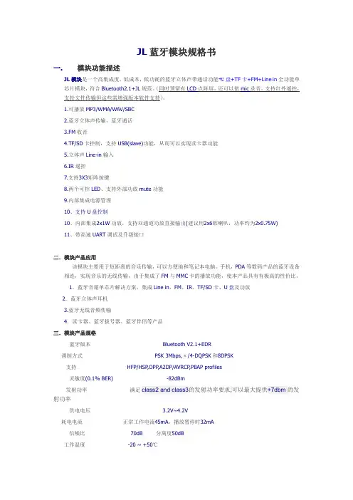
JL蓝牙模块规格书一.模块功能描述JL模块是一个高集成度,低成本,低功耗的蓝牙立体声带通话功能+U盘+TF卡+FM+Line in全功能单芯片模块,符合Bluetooth2.1+JL规范。
(同时预留有LCD点阵屏,还可以做mic录音,支持红外遥控,支持文件传输但这些需增强版本软件支持)。
1.可播放MP3/WMA/WAV/SBC2.蓝牙立体声传输,蓝牙通话3.FM收音4.TF/SD卡控制,支持USB(slave)功能,从而可以实现读卡器功能5.立体声Line-in输入6.IR遥控7.支持3X3矩阵按键8.两个可控LED、支持外部功放mute功能9.内部集成电源管理10、支持U盘控制10、内部集成2x1W功放,支持双通道功放直接输出(建议用2x6欧喇叭,功率约为2x0.75W)11、带高速UART调试及升级接口二.模块产品应用该模块主要用于短距离的音乐传输,可以方便地和笔记本电脑,手机,PDA等数码产品的蓝牙设备相连,实现音乐的无线传输,由于集成了FM与MMC卡的播放功能,使本产品具有有极高的性价比。
1.蓝牙音箱单芯片解决方案,集成Line in、FM、IR、TF/SD卡、U盘及功放2.蓝牙立体声耳机3.蓝牙无线音频传输4.读卡器、蓝牙拔号器、蓝牙伴侣等产品三.模块产品规格蓝牙版本Bluetooth V2.1+EDR调制方式PSK 3Mbps,π/4-DQPSK和8DPSK支持HFP/HSP,OPP,A2DP/AVRCP,PBAP profiles灵敏度(0.1% BER) -82dBm发射功率满足class2 and class3的发射功率要求,可以最大提供+7dbm的发射功率供电电压 3.2V~4.2V耗电电流正常工作电流45mA,播放暂停时32mA信噪比70dB 分离度50dB工作温度-20 ~ +50℃尺寸26mmx19mm x2.05mm八.注意事项:A.关于无线蓝牙的使用环境,无线信号包括蓝牙应用都受周围环境的影响很大,如树木、金属等障碍物会对无线信号有一定的吸收,从而在实际应用中,数据传输的距离受一定的影响。
Network Streamer, CD-Ripper & Music LibraryOwner’s ManualIncluded AccessoriesWelcome to Bluesound, Hi-Fi for the Wi-Fi generation.Bluesound transforms your local digital music library by putting the music of your life right at your fingertips. The clutter of CDs is relegated to a previous era! Your smartphone, desktop or tablet running the Bluesound App now controls your music.Your Bluesound music system is also a sophisticated Internet streaming device that allows you to listen to a wide range of Internet music service providers. Bluesound also provides access to music subscription services featuring extensive catalogs of millions of songs streamed to you over the internet in real time. TuneIn Radio makes every radio station in the world a local station via the magic of the internet.T o take full advantage of all these Bluesound capabilities requires a robust wired home network and a reliable high speed Internet connection, provided by a DSL or Cable modem. Internet access must be contracted and installed by your local Internet Service Provider. For remote areas there are satellite options for high speed internet access.Before signing on to a music subscription or cloud service we suggest that you review your Internet service plan and be sure you have enough internet speed and bandwidth to provide uninterrupted streaming. Most internet service providers offer multiple plans and can help you make the best choice.For detailed instructions on how to control your Bluesound player, visit our website at: .Stereo RCA to RCA Cable 230V AC Power Cord3.5mm Stereo mini Plug to RCA Cable Ethernet Cable120V AC Power Cord Mini Jack to T oslink Adaptor1LED BLINK CODE DESCRIPTIONShort blue flash, then red Powering up, rebooting the unitFlashing green Connecting to Network sharesSolid red Cannot boot; drive errorRed pulse No Internet gatewayWhite pulse Software update availableSolid red Upgrade modeAlternate flashing red and green Upgrading…Flashing blue Mute modeSolid white IndexingSolid blue Connected to Network – ready to use with Bluesound App Flashing red Factory reset in progressSolid purple Hotspot timed outPLAY/PAUSE BUTTON: This button has multiple functions – a visual indicator of network connectivity and a PLAY/PAUSE button. For a full listing of LED Blink Codes, please see #1 – Blink Codes. For an ungrouped Player, press the button to Play and Pause the stream. If listening to an Internet radio stream, the Pause function will work for 30 seconds. At this point, the buffer is full and the stream will Stop. When a Player is grouped, pressing the PLAY/PAUSE button will Mute that Player while other Players continue the stream. The Player’s LED will flash blue when muted.+, - (VOLUME): Toggle either button to vary volume level. Volume level will not change if you press and hold either button. (+): Increase volume level (-): Decrease volume levelPREVIOUS TRACK/NEXT TRACK: These buttons can be used to go back to the previous track ◄◄or skip to the next track ►► in your current playlist.AUDIO OUT: Connect to the corresponding analog audio input of an amplifier, receiver or stereo system.SUBW (SUBWOOFER) OUT: A Subwoofer can also be connected directly to the VAUL T 2i. Connect SUBW OUT to a powered (“active”) subwoofer.COAX OUT: Using a coax cable (not provided), connect one end to the COAX OUT of the VAUL T 2i and the other end to the corresponding coax input of compatible devices such as receivers, computer soundcards or other digital processors.OPTICAL OUT: Using a Digital Optical cable (not provided), connect one end to the OPTICAL OUT of the VAUL T 2i and the other end to the corresponding digital audio input of compatible devices such as receivers, computer soundcards or other digital processors.OPTICAL IN/ANALOG IN: Using a 3.5mm Stereo Audio Cable (provided), connect one end to the Analog In of the VAUL T 2i and the other end to the corresponding analog output of other compatible devices. The source will show as an Analog Input in the Navigation Drawer of the Bluesound app. Using the 3.5mm Mini Jack to Toslink adaptor (included with the VAUL T 2i), a digital optical source can also be added. This will appear as Optical Input in the Navigation Drawer.TRIGGER OUT : A 12V DC signal is available using TRIGGER OUT. The 12V DC signal can be used to control or activate other external devices equipped with a corresponding 12V trigger input using a 3.5mm mono audio cable. IR IN : An infrared extender can be connected to allow for programmable learning remotes to control volume and source selection when a VAUL T 2i is stored in a way that the front panel IR sensor is not visible.USB (TYPE A): Connect a USB mass storage device or Bluetooth adaptor to the USB input. Typical USB mass storage devices compatible with the VAUL T 2i include portable flash memory devices and external hard drives (FAT32 formatted).LAN PORT: To setup the VAUL T 2i, a LAN port for a wired ethernet connection is required. Using the Ethernet cable provided, connect one end of the Ethernet cable to the LAN port of your wired Ethernet broadband router and the other end to the VAUL T 2i’s LAN port.SERVICE: Use the SERVICE port in conjunction with USB (Type B Mini) to initially load firmware on the Player. This is not for consumer use. Only Authorized Bluesound Service personnel can access this USB port and SERVICE control button.AC MAINS INPUT: The VAUL T 2i comes supplied with two separate AC power cords. Select the AC power cord appropriate for your region. Before connecting the plug to the wall outlet, connect firmly the other end of the AC power cord to VAUL T 2i’s AC Mains input socket. Never force the plug into a wall outlet. An adaptor may be necessary in certain regions. Always disconnect the plug from the wall outlet first, before disconnecting the cable from the VAUL T 2i’s AC Mains input socket.FRONT PANEL HEADPHONE JACK: A 3.5mm headphone jack is located on the front of the VAUL T 2i.2345678910111213141516WARNING!THIS IS A FACTORY RESET OF YOUR PLAYER. ALL CUSTOMIZATION INCLUDING WI-FI NETWORK CONFIGURATION, FILE SHARES AND SAVED PLAYLISTS WILL BE LOST. YOU WILL HAVE TO RE-CREATE THESE O NCE C OMPLETE. T HIS P ROCESS I S O NLY R ECOMMENDED I F Y OUR P LAYER I S N OT F UNCTIONING AND AN INTERNET FIRMWARE UPGRADE HAS FAILED. FOR ANY QUESTIONS OR CONCERNS CONTACT AN AUTHORIZED BLUESOUND CUSTOMER REPRESENTATIVE BEFORE PROCEEDING!Steps to Factory Reset:1.Disconnect the player from electrical power.2.Wait 10 seconds3.Reconnect the power4.The LED will flash Blue – once you see it turn Red, touch and hold the Play/Pause icon (it willimmediately turn Green and then back to Red) – do not let go of the LED.5.Once the LED turns back to Red, continue to hold the button for 30 seconds.6.After 30 seconds, the LED will begin to blink red – then release the button.All customization to the Bluesound player will be removed and restored to factory settings.IMPORTANT: Removing your finger from the LED at any time before the LED begins flashing red will cancel the factory reset and leave the player in Upgrade Mode. Just start the steps again to factory reset the player.You will know the factory reset is successful if the player reconnects to the network (plugged in via Ethernet) as if it is a new player. The default player name will be used and the LED will be solid blue.© Bluesound International. Bluesound, the stylized wordmark and “B” logotype, the phrase“HiFi for a wireless generation”, VAULT 2i and all other Bluesound product names and taglinesare trademarks or registered trademarks of Bluesound International, a division of LenbrookIndustries Limited. All other logos and services are trademarks or service marks of theirrespective owners.。
2007INTRODUCTION ............................................................................................................................................................................1MODULE SELECTION ..................................................................................................................................................................3MODULE CATEGORIES MODEL NUMBERS SIGNAL LEVELSINSTALLATION NOTESMODULE SELECTION CHART ........................................................................................................................................................5MUTING ........................................................................................................................................................................................7MICROPHONE INPUT MODULES .. (9)ML-11T Microphone/Line Input with Mute Send/Receive ......................................................................................................9M-01 Series Microphone Input ............................................................................................................................................9M-11S Microphone Input with Mute-Receive ......................................................................................................................10M-21S Microphone Input with Remote Volume Control........................................................................................................10M-41S Microphone Input with Mute-Send ..........................................................................................................................11M-51 Series Microphone Input with Voice Gate ..................................................................................................................11M-61 Series Microphone Input with Compressor................................................................................................................12M-03P High Impedance Microphone Input ..........................................................................................................................12LINE INPUT MODULES . (13)ML-11T Microphone/Line Input with Mute Send/Receive.........................................................................................................13B-01 Series Balanced Line Input ........................................................................................................................................13B-11S Balanced Line Input with Mute-Receive....................................................................................................................14B-21S Balanced Line Input with Remote Volume Control ....................................................................................................14B-41S Balanced Line Input with Mute-Send........................................................................................................................15L-01 Series Line Matching Input ........................................................................................................................................16L-11S Line Matching Input with Mute-Receive....................................................................................................................17L-41S Line Matching Input with Mute-Send........................................................................................................................17U-01 Series Unbalanced Line Input ....................................................................................................................................18U-03 Series Unbalanced Line Input with High/Low Cut Filters ............................................................................................19U-11 Series Unbalanced Line Input with Mute-Receive ......................................................................................................19U-12S Unbalanced Line Input with Variable Mute-Receive Depth ........................................................................................20U-13 Series Unbalanced Line Input with High/Low Cut Filters and Mute-Receive................................................................20U-14R Dual Input Priority with AGC......................................................................................................................................21U-21S Unbalanced Line Input with Remote Volume Control..................................................................................................21U-43 Series Unbalanced Line Input with High/Low Cut Filters and Mute-Send ....................................................................22U-61S Unbalanced Line Input with Compressor ..................................................................................................................23SPECIAL FUNCTION MODULES ..................................................................................................................................................24LINE OUTPUTT-01S Balanced Line Output................................................................................................................................................24T-02S Unbalanced Line Input with Music-On-Hold Output ..................................................................................................24T-12S Unbalanced Line Input with Music-On-Hold Output and Input Mute-Receive..............................................................25TONE GENERATORS-20S Digital Message/Tone with USB.................................................................................................................................25S-01S 1 kHz Sine Wave Test Tone ......................................................................................................................................26S-02S Buzzer/Yelp Tone......................................................................................................................................................26S-04S Switch-Selectable Tone............................................................................................................................................27REMOTE VOLUME CONTROLV-01S Remote Master Volume Control (VCA)........................................................................................................................27SPEAKER PROCESSORE-03Equalizer For F-121....................................................................................................................................................28E-04Equalizer For H-1........................................................................................................................................................28E-05Equalizer For H-2........................................................................................................................................................28E-06Equalizer For H-3........................................................................................................................................................28E-07Low Pass Filter For FB-100/HB-1.. (28)TABLE OF CONTENTSPAGE II TABLE OF CONTENTSTABLE OF CONTENTS PAGE III APPLICATIONS (30)1.Paging Over Background Music (30)2.Telephone Paging and Music-On-Hold (30)3.Banquet Room Sound System (30)4.School Gymnasium Sound System (31)5.Mute Send and Receive Combination Using Two Modules (31)FREQUENTLY ASKED QUESTIONS (31)General1.Which module should I use for a microphone?2.Which module should I use for a wireless microphone receiver?3.Which module should I use for an AM/FM tuner,cassette deck,CD player,computer sound card,juke box,mixer or satellite receiver?4.Which modules should I use for telephone or microphone paging with priority over a music source?5.Which module should I use for Music-On-Hold (MOH)?6.What type of potentiometer do I need for a Remote Volume Control module?7.How do I use one of the 900 Series processor modules?8.What is the proper wiring for the screw terminal type input modules?9.What’s the difference between the “L”Series and “B”Series modules?10.Which modules are for “mute send”?11.Which modules are for “mute receive”?Troubleshooting12.Why won't the M-11 (Microphone Input with Mute-Receive) pass signal?13.Why won't my paging source override my music source?14.Why isn't my condenser microphone working with an M Series module?15.Why is my signal level low with an L Series module?MODULAR PRODUCTS REFERENCE CHART (33)MODULE CROSS-REFERENCE CHART (34)JUMPER SETTINGS CHART (35)CONNECTOR WIRING CHART (36)INTRODUCTION PAGE 1INTRODUCTION Welcome to the TOA 900 SeriesModule Guide!In this guide,you'll find everything you need to takeadvantage of the powerful flexibility of 900 Seriesmodular products — function descriptions; signalflow and wiring diagrams; specifications; jumpersettings; application examples; and other usefulinformation.Understanding the modules will give you thefreedom to configure custom systems FAST without complicated modifications.And as your customers’needs change,you can easily add more inputs ornew functions by simply changing or addingmodules.An electronic version of the guide is also availablefor download at .Ifyou have any questions,please contact TOA ProductSupport at 1-800-733-4748 — we're here to help!TOA Electronics,Inc.Dedicated to Bob Sweet,author of the original 900Series Module Guide,1990.MODULE SELECTION PAGE 3 MODULE SELECTIONMODULE SELECTION CHART PAGE 5 MODULE SELECTION CHARTMUTING PAGE 7 MUTINGMICROPHONE INPUT MODULES PAGE 9M-01ML-11TMICROPHONE INPUT MODULESM-11M-21MICROPHONE INPUT MODULESPAGE 10M-41M-51MICROPHONE INPUT MODULES PAGE 11M-61 M-03MICROPHONE INPUT MODULES PAGE 12B-01ML-11T LINE INPUT MODULES:BALANCED PAGE 13LINE INPUT MODULESB-11 B-21LINE INPUT MODULES:BALANCED PAGE 14B-41LINE INPUT MODULES:BALANCED PAGE 15L-01LINE INPUT MODULES:LINE MATCHING PAGE 16LINE INPUT MODULES:LINE MATCHING PAGE 17L-11L-41U-01LINE INPUT MODULES:UNBALANCEDPAGE 18U-03U-11LINE INPUT MODULES:UNBALANCED PAGE 19U-12 U-13LINE INPUT MODULES:UNBALANCED PAGE 20U-21U-14LINE INPUT MODULES:UNBALANCEDPAGE 21LINE INPUT MODULES:UNBALANCED PAGE 22U-43U-61LINE INPUT MODULES:UNBALANCED PAGE 23T-01 T-02SPECIAL FUNCTION MODULES:LINE OUTPUTPAGE 24SPECIAL FUNCTION MODULEST-12S-20SPECIAL FUNCTION MODULES:LINE OUTPUT PAGE 25SPECIAL FUNCTION MODULES:TONE GENERATORS-01 S-02SPECIAL FUNCTION MODULES:TONE GENERATOR PAGE 26S-04V-01SPECIAL FUNCTION MODULES:TONE GENERATOR PAGE 27SPECIAL FUNCTION MODULES:VOLUME CONTROLE-03 E-04 E-05 E-06 E-07E Series Processor Modules for TOA SpeakersSPECIAL FUNCTION MODULES:SPEAKER PROCESSORPAGE 28E-03E-04E-05E-06E-07SPECIAL FUNCTION MODULES:SPEAKER PROCESSOR PAGE 29E SeriesProcessor Modules for TOA SpeakersAPPLICATIONSPAGE 30APPLICATIONSAPPLICATIONS PAGE 31FREQUENTLY ASKED QUESTIONSFREQUENTLY ASKED QUESTIONSPAGE 32FREQUENTLY ASKED QUESTIONS (continued)MODULAR PRODUCTS REFERENCE PAGE 33MODULE CROSS-REFERENCEPAGE 34Notes:• H Series microphone modules do not provide phantom power.• Original mute-type modules (pre-1994) connect to Mute Bus #1 only.Newer "MK2" mute-type modules connect to both Mute Bus #1 and Mute Bus #2 and have a "MK2" label on the module faceplate.JUMPER SETTINGS PAGE 35Note:1.In many applications,NO jumper changes are required.Mute-Receive and Mute-Send modules connect to both Mute Bus #1 and Mute Bus #2by default.2.Configure the M-11S Mute Response Mode before use - it will not pass signal out-of-the-box.CONNECTOR WIRING PAGE 36TOA E LECTRONICS, I NC.TEL: 800-733-7088FAX: 800-733-9766TOA C ANADAC ORPORATIONT EL: 905-564-3570F AX: 905-564-3569© 2007, TOA Electronics, Inc.。
蓝牙数据传输模块 产品说明书 北京锦天同业科技有限公司2010年8月蓝牙数据传输模块1. 产品特点● 采用CSR BC4-AUDIO FLASH 芯片,内置6M FLASH ● 内置15 bit 线性语音编解码器● 提供增强数据速率(EDR )功能,兼容2Mbps 和3Mbps 的数据传输速率● 具有PIO0~PIO3、射频接口、SPI 、UART 等多种接口,用户可定制软件,实现各种蓝牙应用 ● 支持与WLAN (802.11)共存2. 产品性能指标蓝牙协议版本蓝牙协议 v2.0,兼容v1.2频率2.4GHz (ISM band)调制方式 GFSK(Gaussian Frequency Shift Keying) 发射功率 ≤4dBm, Class 2灵敏度 ≤-84dBm @ 0.1% BER 通信距离 10m 视距(加天线)通讯速率 最低:1200bps@2%Err ,9600bps@1%Err 最高:3Mbps@1%Err安全特性 Authentication and encryption 应用框架支持 SPP,FTP etc.供电电源 3.0~3.6V ,3.3V TYP 工作温度-20~+55 Centigrade3. 尺寸和引脚定义尺寸图(俯视)引脚定义(俯视)注:尺寸图中与焊盘有关的均表示到焊盘中心的距离,图中的邮票孔左右对称邮票孔定义(仰视)引脚定义(依据上图所标的引脚序号):序号 引脚 说明1UART_RTS 串口请求发送 2 UART_TX 串口数据发送 3 UART_CTS 串口清除发送 4 UART_RX 串口数据输入 5 SPI_MOSI 串行外围接口数据输入 6 SPI_CSB 串行外围接口片选信号 7 SPI_CLK 串行外围接口时钟信号 8 SPI_MISO 串行外围接口数据输出9 3V3 3.3V 电源输入 10 3V3 3.3V 电源输入 11 RESET 低电平复位,至少5ms12 GND 地13 PIO3 输入端口,SET 脚,低电平为数据传输模式,高电平为参数设置模式14 PIO2 可编程输入/输出口 15 PIO1 可编程输入/输出口 16PIO0可编程输入/输出口4. 蓝牙模组AT 指令说明注意:只有当蓝牙模组工作在“参数设置状态”时(PIO(3)置高)才允许执行参数设置命令。
蓝牙模块软件说明书目录1.低功耗蓝牙(BLE)4.1 模块简介 (1)1.1. 功能简介 (1)1.2. 主要功能特点 (1)1.3. 模组电气特性 (2)1.4. 模组蓝牙功耗对照表 (2)1.5. 工作模式示意图 (3)1.6. 模块脚位图 (4)1.6.1.模块 7x7 脚位图 (4)1.6.2.模块 5x5 脚位图 (6)1.7. 引脚功能 (6)1.7.1 模块 7x7 引脚功能 (6)1.7.2.模块 5x5 引脚功能 (8)2.模块软件指令说明 (11)2.1. 命令表 (11)2.2. SPI 软件命令格式说明 (15)2.2.1. SPI 写命令 (15)2.2.2. SPI 读命令 (15)2.3. UART 命令格式说明 (16)2.3.1. UART 读写命令 (16)2.3.2. UART 接收 BLE 数据 (17)2.4. 蓝牙软件读写说明 (17)2.4.1. 模块 UUID 说明 (17)2.4.2. 模组蓝牙通道操作软件说明 (17)2.5. 命令说明 (18)3.APP 工具使用说明 (35)3.1.APP 读取及设置模组参数 (36)3.2.接收发送透传数据 (37)4.联系我们 (38)5.文件修订说明 (39)1. 低功耗蓝牙( BLE )1 4.1 模块简介1.1. 功能简介蓝牙模块支持从机模式。
支持桥接模式(透传模式)和直驱模式。
模块通过初始设置后会自动进行广播,已打开特定 APP 的手机会对其进行扫描和对接,成功之后便可以通过 BLE 协议对其进行控制。
桥接模式:用户 CPU 可以通过模块的通用 UART 或 SPI 和移动设备进行双向通讯,用户也可以通过特定的指令,对模块的蓝牙参数进行管理控制。
用户数据的具体含义由上层应用程序自行定义。
移动设备可以通过 APP 对模块进行写操作,写入的数据将通过 UART 或 SPI 发送给用户的 CPU。
模块收到来自用户 CPU数据包后,将自动转发给移动设备。
蓝牙模块使用说明一、模块简介:1、芯片简介该蓝牙模块采用台湾胜普科技有限公司的BMX-02X模块为核心,它采用CSR BLUEcore4-External芯片并配置8Mbit的软件存储空间,成本低,使用方便。
CSR BlueCore4是英国Cambridge Silicon Radio(CSR)公司日前推出的第四代蓝牙硅芯片。
这种硅芯片用于蓝牙技术推广小组(SIG)推出的增强数据传输率(EDR)蓝牙。
CSR的BlueCore4的数据传输率将比现有的v 1.2蓝牙装置快三倍,并且使蓝牙移动电话或手机的耗电量较低。
蓝牙EDR的最大数据传输率为每秒2.1兆比特,而目前v1.2标准传输率则为每秒721千比特。
传输率的提高意味着对一个特定量的数据来说,EDR无线电的工作将比v1.2无线电快三倍,从而减少耗电量,大大有利于依赖蓄电池的移动设备。
CSR BlueCore4完全能与现有蓝牙v1.1和v1.2装置兼容。
蓝牙EDR用一种相移键控(PSK)调制模式取代标准传输率的Gaussian频移键控(GFSK),实现更高的数据传输率。
CSR BlueCore4正在以两种形式提供——一种用于外部“快闪”存储器,一种用于掩模ROM。
BlueCore4-External以一种8×8mm BGA(球形格栅矩阵)封装提供,是十分灵活的解决方案,能够适应迅速更新的市场。
例如,由于BlueCore是目前可以得到的唯一能够支持蓝牙v1.2规格的所有强制和可选功能的硅芯片,BlueCore4-External为PC应用程序提供了理想的解决方案,使它们得益于以三倍速度的传输率无线传输文件,或者同时操作多个高需求的蓝牙链路。
鉴于蓝牙固件安装在芯片只读存储器上,CSR BlueCore4-ROM 的成本较低,占用面积小得多(在小片尺寸包装中为3.8×4mm,在与BC2-ROM和BC3-ROM引脚兼容的BGA中为6×6mm)。
蓝牙音频模块说明文档(5V)
一、外观
实际产品,已经焊接了插针,默认为90度弯针
二、端口说明:
1、+5V 电源:接电源正极,电压范围4.2V~5V ,请确保供电在此范围内,超这个范围可能损坏模块,或者导致工作不正常;
2、地:GDN 接电源负极,也是音频的地,此地必需分开两根地线分别接电源地跟音频地;
3、左声道:接功放板左声道输入,或者耳机的左声道,建议在该输出端口接入一个电容(视功放所匹配的输入而定);
4、右声道:接功放板右声道输入,或者耳机的右声道,建议在该输出端口接入一个电容(视功放所匹配的输入而定);
5、静音输出端口:该端口预置为高电平,当静音时该端口输出低电平;
6、状态指示灯:当蓝牙未连接时,该灯快闪,一旦蓝牙连接成功则变为慢闪;
7、预留端口:该端口已经上拉到5V ,当该端口给一个低电平触发后关机,当再次给该端口一个低电平复开机。
系统典型接线图:
注意:从蓝牙音频模块到电源或者到音频接口,请采用焊接的方式,不要采用插线的方式,接触电阻比较大会引入噪声。
三、使用注意事项:
1、供电电源:蓝牙音频模块属于对高频干扰敏感的电路,建议采用线性稳压电源,若采用DC-DC供电时,请加入LC滤波,降低电源谐波干扰,尤其采用手机充电器等开关电源,电源纹波可能致使蓝牙不能正常连接,而且这类的5V输出,往往在5.1V~5.4V之间,超过了蓝牙音频模块的工作电压;
当采用手机适配器等开关电源工作时,请加这个供电电路,电感可不加。
2、接地:由于音频信号对于接地点引起的干扰比较敏感,可以在蓝牙模块的输出插针上面焊两根地结,一根接到电源的负极(GND),另外一根接到功放板的音频输入地,尽量焊在线路板上,不要采用引线接连(容易受干扰),并且建议可以多试一下那个接地点干扰最小;
3、天线干扰:蓝牙天线极其容易受到高频,或者强电磁信号干扰,相对来说尽量远离功放板的强信号的地方,并且天线不能紧挨着金属物品,保持一定的距离;
4、外壳屏蔽:由于金属外壳的机壳对于蓝牙信号有屏蔽作用,可能衰减蓝牙信号致使接收不良,请保持在有相应的开孔,或者外露。
注:对于一些功放板容易受到干扰,干扰不容易处理的情况,请分开供电,即功放板单独一路供电,蓝牙模块一路供电。
四、附加电路:
1、状态指示灯接线图
由于模块的驱动能力较弱,建议LED灯采用红色LED灯,或者外加三极管驱动LED灯;
2、静音端口
(1)、对于有静音功能的功放板,如果为低电平静音的可以直接接入,对于高电平表静音请加一级三极管作为反相,正常播音时静音处于输出高电平约为3V左右;
(2)、对于没有静音输入的功放板可以自己增加静音电路
3、3.7V与5V的板子修改
对于5V版本跟3.7V版本是同一块基本,只是差了一个二极管而已,可以自行改动,以适应新的供电电压。
一3.7V 转5V的,可以在电源正极,串入一个二极管,即可以工作在5V的电压。
二5V转3.7V,可以参考下图
四、常见问题处理:
1、电流声:
引起原因为地线干扰造成,建议蓝牙模块输出端子不要用插线的输出端子必需焊线,特别是地线要焊的,而且线不能太长,越短越好,尽量粗一些。
在蓝牙模块引出的地线,电源地跟音频地也必需分开,不能只接一根地线。
音频地在功放板接地点的问题,必需接在功放音频输入端的地,这个接地点可以尝试在不同的位置焊接,达到最低的电流声音。
分开供电是解决这个电流声,比较好的一个处理方法。
2、蓝牙信号弱:
当模块可以正常工作即蓝牙指示灯正常的快闪,蓝牙的接收距离很近,不能超过5米,一般为电源供电有干扰(开关电源干扰),或者供电电压不正常,请参考文档的处理开关电源干扰时加那个二极管跟电容。
``
3、蓝牙搜不到信号:
搜不到蓝牙信号一个重要的原因就是电源造成,除了供电电压不正常,一般都是电源的的纹波太高了,对于蓝牙模块的高频信号造成了很大的干扰,用前面处理电源干扰的方法处理就行了。
另外一种情况就下,同一部手机连接过多个模块,虽然蓝牙号相同,但内部地址有差异,可以将原来的蓝牙号删除掉,再搜号连接。
4、底噪处理:
关于底噪有两种,一种蓝牙处理待机进的搜信号的底噪,这种是固有的,但声响不会很大,只有一点点,可能通过静音(MUTE)处理掉。
另外一种底噪,是由于干扰或者布线引起的,可修改线路还有改进接地点来解决,可以对照上面所述的方法处理。