HC系列蓝牙产品用户使用指导说明书201104修订-1
- 格式:pdf
- 大小:2.14 MB
- 文档页数:11
蓝牙远距离产品说明书一、远距离蓝牙产品优势:1、蓝牙产品是光激励、CDMA、休眠唤醒、蓝牙通信高新技术结晶。
2、读卡速度快,读卡距离远,具有良好的方向性,读卡距离可控制(1-5米、5-10米、10-20米可调)。
10-40公里时速可不停车读卡,不会出现随着使用时间而读卡距离变近。
3、上下坡道、弯道出入口不停车读卡,避免车辆熄火,半坡起动。
4、不受车辆防护膜(如防暴膜)影响,适用于所有车辆。
5、不停车,不开窗读卡;恶劣的天气车主不再受车窗外的风雨雪影响。
6、不停车读卡,大大提高车流通过量,交通高峰期不再堵车排长龙现象。
7、80°角光激励定向读卡之间无互相干扰(采用先进的蓝牙通信技术与码分多址),方向性好,有效解决前后左右车道互扰问题。
8、433MHZ频率,对人没有辐射损害,低频低功率。
9、卡稳定性好,产品抗干扰、抗衰落能力强,不受其它通信产品干扰(如:手机等无线通信产品)。
手机通话不会烧卡。
同频率无线、天气环境的影响(如下雨天气读卡稳定)10、韦根26/34,RS232C/485适应接口,具有良好的拓展性可在其它停车场、高速公路、远距离识别领域通用。
11、与现有的IC/ID卡设备完全兼容。
12、可将停车场划为多个分区,分别允许不同号码的蓝牙卡进入。
13、提升小区形象,使你的物业管理与众不同。
二、远距离蓝牙概述随着21世纪社会经济的迅速发展,人们生活的节奏更加快,对生活的质量也要要求更高。
近年来,无线移动通信的发展日新月异,新技术也层出不穷。
对于蓝牙通信技术里的远距离不停车收费等技术有什么特点?它们之间又有何异同点?它们到底能为用户提供什么样的服务?蓝牙光励远距离产品是光激励、休眠唤醒、蓝牙通信高新技术结晶,采用红外光激励定位与扩频多址数字式技术,蓝牙通讯相结合的方法,同时具有红外和微波二种方式的优点,又克服了二者的缺点。
全智蓝牙让你真正体验到不停车读卡进出车场的享受!可以预计,蓝牙技术将会给现代信息社会中,远距离蓝牙不停车读卡带来一场新的革命。
使用蓝牙的流程解说明1. 引言蓝牙是一种无线通信技术,用于在短距离范围内传输数据。
它在各种设备中广泛应用,如手机、平板电脑、蓝牙耳机等。
在本文档中,我们将解释如何使用蓝牙的流程。
我们将探讨蓝牙的设置、配对、连接和数据传输等。
2. 设置蓝牙在开始使用蓝牙之前,首先需要确保设备以及蓝牙功能已经启用,并进行合适的设置。
遵循以下步骤进行蓝牙设置:1.打开设备的设置菜单。
2.在设置菜单中查找并点击“蓝牙”选项。
3.在蓝牙设置页面上,找到并点击“启用蓝牙”按钮。
4.等待设备搜索附近的蓝牙设备。
3. 配对蓝牙设备一旦蓝牙已经处于启用状态,我们可以开始配对其他蓝牙设备。
根据以下步骤进行蓝牙设备配对:1.在蓝牙设置页面上,点击“搜索设备”按钮。
2.等待设备搜索附近的蓝牙设备。
3.选择所需的蓝牙设备名称。
4.如果需要,输入蓝牙设备的配对码。
5.点击“配对”按钮。
4. 连接蓝牙设备一旦配对成功,我们就可以连接到蓝牙设备上。
按照以下步骤进行蓝牙设备的连接:1.在蓝牙设置页面上,找到已配对的蓝牙设备列表。
2.选择所需的蓝牙设备名称。
3.点击“连接”按钮。
4.等待设备建立蓝牙连接。
5. 数据传输连接成功后,我们可以开始在设备之间传输数据。
以下是通过蓝牙传输数据的一些常见方式:•传输文件:在设备之间传输文件,如照片、音频文件等。
•传输文本:发送文本消息或笔记等。
•控制设备:通过蓝牙控制其他设备,如蓝牙音箱、蓝牙智能家居设备等。
6. 断开蓝牙连接在完成蓝牙通信后,我们应该及时断开蓝牙连接,以节省设备的电量。
按照以下步骤进行蓝牙断开连接:1.在蓝牙设置页面上,找到已连接的蓝牙设备列表。
2.选择所需的蓝牙设备名称。
3.点击“断开连接”按钮。
7. 结论使用蓝牙进行设备之间的通信变得越来越普遍,逐渐渗透到各个领域。
通过本文档,我们了解了使用蓝牙的流程,包括设置蓝牙、配对蓝牙设备、连接蓝牙设备、数据传输和断开蓝牙连接。
希望本文档能对您使用蓝牙有所帮助。
使用蓝牙的流程解说明1. 蓝牙技术简介蓝牙技术是一种无线通信技术,它使用短波无线电信号传送数据,适用于各种设备之间的通信。
蓝牙技术的主要特点包括低功耗、短距离通信、简单易用等。
在现代生活中,我们可以通过蓝牙技术连接手机、耳机、音箱、键盘等各种设备。
2. 使用蓝牙的流程使用蓝牙设备进行通信的流程可以分为以下几个步骤:2.1 打开蓝牙设备在使用蓝牙设备之前,首先需要确保设备的蓝牙功能已经打开。
在手机等移动设备上,通常可以在设置菜单中找到蓝牙选项,并通过切换按钮将蓝牙功能开启。
2.2 搜索可连接的蓝牙设备一旦蓝牙设备功能打开,就可以开始搜索附近可连接的蓝牙设备。
在手机等移动设备上,可以在蓝牙设置页面中点击“搜索设备”或类似按钮来开始搜索。
2.3 选择并配对设备在搜索到可连接的蓝牙设备后,可以从列表中选择要连接的设备。
选择设备后,通常需要进行配对操作以建立设备之间的信任关系。
配对的方法可以是输入配对码、点击确认对话框等,具体方法取决于设备的不同。
2.4 连接蓝牙设备配对成功后,就可以连接蓝牙设备了。
连接蓝牙设备通常只需要点击设备名称或类似按钮即可。
2.5 使用蓝牙设备进行通信一旦蓝牙设备连接成功,就可以开始使用蓝牙设备进行通信了。
例如,连接蓝牙耳机后,可以通过手机播放音乐或接听电话;连接蓝牙音箱后,可以通过手机播放音乐。
3. 注意事项在使用蓝牙设备时,需要注意以下几点:•确保周围没有过多的干扰源,以确保蓝牙设备的稳定连接;•提前备好相关配对码,以便在配对时使用;•保持蓝牙设备与连接设备的距离在有效范围内;•及时关闭蓝牙设备,以节省电力。
4. 结语蓝牙技术在现代生活中的应用越来越广泛,通过简单的几个步骤,我们可以轻松地连接和使用蓝牙设备进行通信。
无论是连接耳机、音箱还是键盘,都可以通过蓝牙实现便捷的无线通信。
希望通过本文的介绍,您能更好地掌握蓝牙设备的使用流程。
HC Serial Bluetooth ProductsUser Instructional Manual1 IntroductionHC serial Bluetooth products consist of Bluetooth serial interface module and Bluetooth adapter, such as:(1) Bluetooth serial interface module:Industrial level: HC-03, HC-04(HC-04-M, HC-04-S)Civil level: HC-05, HC-06(HC-06-M, HC-06-S)HC-05-D, HC-06-D (with baseboard, for test and evaluation)(2) Bluetooth adapter:HC-M4HC-M6This document mainly introduces Bluetooth serial module. Bluetooth serial module is used for converting serial port to Bluetooth. These modules have two modes: master and slaver device. The device named after even number is defined to be master or slaver when out of factory and can’t be changed to the other mode. But for the device named after odd number, users can set the work mode (master or slaver) of the device by AT commands.HC-04 specifically includes:Master device: HC-04-M, M=masterSlave device: HC-04-S, S=slaverThe default situation of HC-04 is slave mode. If you need master mode, please state it clearly or place an order for HC-O4-M directly.The naming rule of HC-06 is same.When HC-03 and HC-05 are out of factory, one part of parameters are set for activating the device. The work mode is not set, since user can set the mode of HC-03, HC-05 as they want.The main function of Bluetooth serial module is replacing the serial port line, such as:1. There are two MCUs want to communicate with each other. One connects to Bluetooth master device while the other one connects to slave device. Their connection can be built once the pair is made. This Bluetooth connection is equivalently liked to a serial port line connection including RXD, TXDsignals. And they can use the Bluetooth serial module to communicate with each other.2. When MCU has Bluetooth salve module, it can communicate with Bluetooth adapter of computers and smart phones. Then there is a virtual communicable serial port line between MCU and computer or smart phone.3. The Bluetooth devices in the market mostly are salve devices, such as Bluetooth printer, Bluetooth GPS. So, we can use master module to make pair and communicate with them.Bluetooth Serial module’s operation doesn’t need drive, and can communicate with the other Bluetooth device who has the serial. But communication between two Bluetooth modules requires at least two conditions:(1) The communication must be between master and slave.(2) The password must be correct.However, the two conditions are not sufficient conditions. There are also some other conditions basing on different device model. Detailed information is provided in the following chapters.In the following chapters, we will repeatedly refer to Linvor’s (Formerly known as Guangzhou HC Information Technology Co., Ltd.) material and photos.2 Selection of the ModuleThe Bluetooth serial module named even number is compatible with each other; The salve module is also compatible with each other. In other word, the function of HC-04 and HC-06, HC-03 and HC-05 are mutually compatible with each other. HC-04 and HC-06 are former version that user can’t reset the work mode (master or slave). And only a few AT commands and functions can be used, like reset the name of Bluetooth (only the slaver), reset the password, reset the baud rate and check the version number. The command set of HC-03 and HC-05 are more flexible than HC-04 and HC-06’s. Generally, the Bluetooth of HC-03/HC-05 is recommended for the user.Here are the main factory parameters of HC-05 and HC-06. Pay attention to the differences:HC-05 HC-06 Master and slave mode can be switched Master and slave mode can’t be switched Bluetooth name: HC-05 Bluetooth name: linvorPassword:1234 Password:1234Master role: have no function to remember the lastpaired salve device. It can be made paired to anyslave device. In other words, just set AT+CMODE=1 when out of factory. If you want HC-05 to remember the last paired slave device address like HC-06, you can set AT+CMODE=0 after paired with the other device. Please refer thecommand set of HC-05 for the details.Master role: have paired memory to remember last slave device and only make pair with that device unless KEY (PIN26) is triggered by high level. The default connected PIN26 is low level. Pairing: The master device can not only make pairwith the specified Bluetooth address, likecell-phone, computer adapter, slave device, but also can search and make pair with the slave device automatically. Typical method: On some specific conditions, master device and slave device can make pair with each other automatically. (This is the defaultmethod.)Pairing: Master device search and make pair with the slave device automatically.Typical method: On some specific conditions, master and slave device can make pair with each other automatically.Multi-device communication: There is only point to point communication for modules, but the adapter can communicate with multi-modules.Multi-device communication: There is only point to point communication for modules, but the adapter can communicate with multi-modules. AT Mode 1: After power on, it can enter the ATmode by triggering PIN34 with high level. Thenthe baud rate for setting AT command is equal tothe baud rate in communication, for example:9600.AT mode 2: First set the PIN34 as high level, orwhile on powering the module set the PIN34 to behigh level, the Baud rate used here is 38400 bps.Notice: All AT commands can be operated only AT Mode: Before paired, it is at the AT mode. After paired it’s at transparent communication.when the PIN34 is at high level. Only part of theAT commands can be used if PIN34 doesn’t keepthe high level after entering to the AT mode.Through this kind of designing, set permissions forthe module is left to the user’s external controlcircuit, that makes the application of HC-05 is veryflexible.During the process of communication, the modulecan enter to AT mode by setting PIN34 to be highlevel. By releasing PIN34, the module can go back to communication mode in which user can inquire some information dynamically. For example, toinquire the pairing is finished or not.During the communication mode, the module can’t enter to the AT mode.Default communication baud rate: 9600, 4800-1.3M are settable.Default communication baud rate: 9600, 1200-1.3M are settable. KEY: PIN34, for entering to the AT mode.KEY: PIN26, for master abandons memory. LED1: PIN31, indicator of Bluetooth mode. Slowflicker (1Hz) represents entering to the AT mode2,while fast flicker(2Hz) represents entering to the AT mode1 or during the communication pairing. Double flicker per second represents pairing is finished, the module is communicable. LED2: PIN32, before pairing is at low level, after the pairing is at high level. The using method of master and slaver’s indicator is the same.Notice: The PIN of LED1 and LED2 are connectedwith LED+.LED: The flicker frequency of slave device is 102ms. If master device already has the memory of slave device, the flicker frequency during the pairing is 110ms/s. If not, or master has emptied the memory, then the flicker frequency is 750m/s. After pairing, no matter it’s a master or slave device, the LED PIN is at high level.Notice: The LED PIN connects to LED+ PIN.Consumption: During the pairing, the current is Consumption: During the pairing, the current isfluctuant in the range of 30-40mA. The mean current is about 25mA. After paring, no matter processing communication or not, the current is 8mA. There is no sleep mode. This parameter is same for all the Bluetooth modules. fluctuant in the range of 30-40 m. The mean current is about 25mA. After paring, no matter processing communication or not, the current is 8mA. There is no sleep mode. This parameter is same for all the Bluetooth modules.Reset: PIN11, active if it’s input low level. It can be suspended in using.Reset: PIN11, active if it’s input low level. It can be suspended in using. Level: CivilLevel: CivilThe table above that includes main parameters of two serial modules is a reference for user selection.HC-03/HC-05 serial product is recommended.3. Information of PackageThe PIN definitions of HC-03, HC-04, HC-05 and HC-06 are kind of different, but the package sizeis the same: 28mm * 15mm * 2.35mm.The following figure 1 is a picture of HC-06 and its main PINs. Figure 2 is a picture of HC-05 and its main PINs. Figure 3 is a comparative picture with one coin. Figure 4 is their package size information. When user designs the circuit, you can visit the website of Guangzhou HC Information Technology Co., Ltd. ( ) to download the package library of protle version.Figure 1 HC-06 Figure 2 HC-05Figure 3 Comparative picture with one coinFigure 4 Package size information4. The Using and Testing Method of HC-06 for the First TimeThis chapter will introduce the using method of HC-06 in detail. User can test the module according to this chapter when he or she uses the module at the first time.PINs description:PIN1 UART_TXD , TTL/CMOS level, UART Data outputPIN2 UART_RXD, TTL/COMS level, s UART Data inputPIN11 RESET, the reset PIN of module, inputting low level can reset the module, when the module is in using, this PIN can connect to air.PIN12 VCC, voltage supply for logic, the standard voltage is 3.3V, and can work at 3.0-4.2VPIN13 GND PIN22 GNDPIN24 LED, working mode indicatorSlave device: Before paired, this PIN outputs the period of 102ms square wave. After paired, this PIN outputs high level.Master device: On the condition of having no memory of pairing with a slave device, this PIN outputs the period of 110ms square wave. On the condition of having the memory of pairing with a slave device, this PIN outputs the period of 750ms square wave. After paired, this PIN outputs high level.PIN26 For master device, this PIN is used for emptying information about pairing. After emptying, master device will search slaver randomly, then remember the address of the new got slave device. In the next power on, master device will only search this address.Figure 5 The circuit 1In principle, HC-06 can work when UART_TXD, UART_RXD, VCC and GND are connected. However, for better testing results, connecting LED and KEY are recommended (when testing the master).Where, the 3.3V TXD of MCU connects to HC-06’s UART_RXD, the 3.3V RXD of MCU connects to HC-06’s UART_TXD, and 3.3V power and GND should be connected. Then the minimum system is finished.Note that, the PIN2:UART_RXD of Bluetooth module has no pull-up resistor. If the MCU TXD doesn’t have pull-up function, then user should add a pull-up resistor to the UART_RXD. It may be easy to be ignored.If there are two MCU which connect to master and slave device respectively, then before paired(LED will flicker) user can send AT commands by serial port when the system is power on. Please refer to HC-04 and HC-06’s data sheet for detailed commands. In the last chapter, the command set will be introduced. Please pay attention to that the command of HC-04/HC-06 doesn’t have terminator. For example, consider the call command, sending out AT is already enough, need not add the CRLF (carriage return line feed).If the LED is constant lighting, it indicates the pairing is finished. The two MCUs can communicatewith each other by serial port. User can think there is a serial port line between two MCUs.Figure 6 is the block diagram of Bluetooth baseboard. This kind of circuit can amplify Bluetooth module’s operating voltage to 3.1-6.5V. In this diagram, the J1 port can not only be connected with MCU system of 3.3V and 5V, but also can be connected with computer serial port.Figure 6 The circuit 2(3) AT command testBefore paired, the mode of HC-04 and HC-06 are AT mode.On the condition of 9600N81, OK will be received when user send the two letters AT. Please refer to the last chapter of datasheet for other commands of HC-06. Please pay attention to that sending out AT is already enough, need not add the CRLF (carriage return line feed).The command set of Version V1.4 doesn’t include parity. The version V1.5 and its later version have parity function. Moreover, there are three more commands of V1.5 than V1.4. They are:No parity (default) AT+PNOdd parity AT+POEven parity AT+PEDo not let the sending frequency of AT command of HC-06 exceed 1Hz, because the command ofHC-06 end or not is determined by the time interval.(4) Pairing with adapterUser can refer to the download center of the company’s website for “The Introduction of IVT” that introduces the Bluetooth module makes pair with computer adapter. That document taking HC-06-D for example introduces how the serial module makes pair with the adapter. That method is like to make pairwith cell-phone. But the difference is that cell-phone need a third-party communication software to help.It’s liked the kind of PC serial helper of and the hyper terminal. A software named “PDA serial helper” provided by our company is suitable for WM system. It has been proven that this serial module is supported by many smart phone systems’ Bluetooth, such as, sybian, android, windows mobile and etc.(5) Pairing introductionHC-06 master device has no memory before the first use. If the password is correct, the mater device will make pair with the slave device automatically in the first use. In the following use, the master device will remember the Bluetooth address of the last paired device and search it. The searching won’t stop until the device is found. If master device’s PIN26 is input high level, the device will lose the memory. In that occasion, it’ll search the proper slave device like the first use. Based on this function,the master device can be set to make pair with the specified address or any address by user.(6) Reset new password introductionUser can set a new password for the HC-06 through AT+PINxxxx command. But the new passwordwill become active after discharged all the energy of the module. If the module still has any energy, theold one is still active. In the test, for discharging all the system energy and activating the new password,we can connect the power supply PIN with GND about 20 seconds after the power is cut off. Generally, shutting down the device for 30 minutes also can discharge the energy, if there is no peripheral circuit helps discharge energy. User should make the proper way according to the specific situation.(7) Name introductionIf the device has no name, it’s better that user doesn’t try to change the master device name. The name should be limited in 20 characters.Summary: The character of HC-06: 1 not many command 2 easy for application 3 low price. It’s good for some specific application. HC-04 is very similar with HC-06. Their only one difference is HC-04 is for industry, HC-06 is for civil. Except this, they don’t have difference.The following reference about HC-04 and HC-06 can be downloaded from company website :HC-06 datasheet .pdf (the command set introduction is included)HC-04 datasheet .pdf (the command set introduction is included)IVT BlueSoleil-2.6 (IVT Bluetooth drive test version)Bluetooth FAQ.pdfHC-04-D(HD-06-D)datasheet(English).pdfHC-06-AT command software (test version) (some commands in V1.5 is not supported by V1.4) PCB package of Bluetooth key modules (PCB package lib in protel)IVT software manual.pdf (introduce how to operate the modern and make pairwith Bluetooth module)PDA serial test helper.exe (serial helper used for WM system)5 manual for the first use of HC-05This chapter will introduce how to test and use the HC-05 if it’s the first time for user to operate it.(1) PINs descriptionPIN1 UART_TXD, Bluetooth serial signal sending PIN, can connect with MCU’s RXD PINPIN2 UART_RXD, Bluetooth serial signal receiving PIN, can connect with the MCU’s TXD PIN, there is no pull-up resistor in this PIN. But It needs to be added an eternal pull-up resistor.PIN11 RESET, the reset PIN of module, inputting low level can reset the module, when the module is in using, this PIN can connect to air.PIN12 VCC, voltage supply for logic, the standard voltage is 3.3V, and can work at 3.0-4.2V PIN13 GNDPIN31 LED1, indicator of work mode. Has 3 modes:When the module is supplied power and PIN34 is input high level, PIN31 output 1Hz square wave to make the LED flicker slowly. It indicates that the module is at the AT mode, and the baud rate is 38400;When the module is supplied power and PIN34 is input low level, PIN31 output 2Hz square wave to make the LED flicker quickly. It indicates the module is at the pairable mode. IfPIN34 is input high level, then the module will enter to AT mode, but the output of PIN31 is still 2Hz square wave.After the pairing, PIN31 output 2Hz square ware.Note: if PIN34 keep high level, all the commands in the AT command set can be in application. Otherwise, if just excite PIN34 with high level but not keep, only some command can be used. More information has provided at chapter 2.PIN32 Output terminal. Before paired, it output low level. Once the pair is finished, it output highlevel.PIN34 Mode switch input. If it is input low level, the module is at paired or communication mode. If it’s input high level, the module will enter to AT mode. Even though the module is atcommunication, the module can enter to the AT mode if PIN34 is input high level. Then it will go back to the communication mode if PIN34 is input low level again.(2) Application circuit 1 (connect to the 3.3V system)Figure 7 Application 1(3) Application circuit 2 (connect to 5V serial system or PC serial)Figure 8 Application circuit 2(4) AT command testThis chapter introduces some common commands in use. The detail introduction about HC-05 command is in HC-0305 AT command set.Enter to AT mode:Way1: Supply power to module and input high level to PIN34 at the same time, the module will enter to AT mode with the baud rate-38400.Way2: In the first step, supply power to module; In the second step, input high level to PIN34. Then the module will enter to AT mode with the baud rate-9600. Way1 is recommended.Command structure: all command should end up with “\r\n” (Hex: 0X0D X0A) as the terminator. Ifthe serial helper is installed, user just need enter “ENTER” key at the end of command.Reset the master-slave role command:AT+ROLE=0 ----Set the module to be salve mode. The default mode is salve.AT+ROLE=1 ----Set the module to be master mode.Set memory command:AT+CMODE=1Set the module to make pair with the other random Bluetooth module (Not specified address). The default is this mode.AT+CMODE=1Set the module to make pair with the other Bluetooth module (specified address). If set the module to make pair with random one first, then set the module to make pair with the Bluetooth module has specified address. Then the module will search the last paired module until the module is found.Reset the password commandAT+PSWD=XXXXSet the module pair password. The password must be 4-bits.Reset the baud rateAT+UART== <Param>,<Param2>,<Param3>.More information is provided at HC-0305 command setExample:AT+UART=9600,0,0 ----set the baud rate to be 9600N81Reset the Bluetooth nameAT+NAME=XXXXXSummary:HC-05 has many functions and covers all functions of HC-06. The above commands are the most common ones. Besides this, HC-05 leaves lots of space for user. So HC-05 is better than HC-06 andrecommended. HC-03 is similar with HC-05. The above introduction also suits HC-03 The following reference about HC-03 and HC-05 can be downloaded from company website :HC-03 datasheet .pdf (the command set introduction is included)HC-05 datasheet .pdf (the command set introduction is included)IVT BlueSoleil-2.6 (IVT Bluetooth drive test version)Bluetooth FAQ.pdfPCB package of Bluetooth key modules (PCB package lib in protel)IVT software manual.pdf (introduce how to operate the modern and make pair withBluetooth module)PDA serial test helper.exe (serial helper used for WM system)HC-03/05 Bluetooth serial command set.pdf6. Ordering informationThe website of Guangzhou HC Information Technology Co., Ltd is The contact information is provided at the company website.Order Way: If you want our product, you can give order to the production center of our company directly or order it in Taobao. There is a link to Taobao in our company website.Package: 50 pieces chips in an anti-static blister package. The weight of a module is about 0.9g. The weight of a package is about 50g.Please provide the product’s model when you order:HC-04-M HC-04 master moduleHC-04-S HC-04 slave moduleHC-06-M HC-06 master moduleHC-06-S HC-06 slave moduleHC-03HC-05 HC-03/05 can be preset to be master module or slave module.。

Bluetooth Headset使用說明書1目錄目錄包裝內容物主機按鍵功能接聽來電配對操作One Touch語音快速撥號簡介One Touch─AndroidOne Touch─iOS支架安裝支架與充電座使用方式充電方式123456 7~9 10~12131415歡迎使用U CLEAR Commander感謝您購買UCLEAR Commander車用藍牙耳機,此耳機專為全球駕駛人士開發的車用藍牙耳機,配合UCLEAR全球獨創「One Touch」藍牙語音播號和快速連接功能,實現免觸碰手機播號通話,準確率可達99.5%以上,使您在駕駛時能完全釋放雙手,專注於路況的同時,也能繼續保持聯繫通話。
車用12V充電器USB充電線耳塞套(L、M、S)Commander主機車用遮陽板專用支架多功能充電插座掛繩透明耳勾說明書2包裝內容物U CLEAR Commander 簡介開/關機接聽/掛斷多功能按鍵LED指示燈降低音量音量增大3主機按鍵功能開機如耳機在車用遮陽板支架或充電插座上時,取出後便自動開機 多功能按鍵長按5秒即可開機關機耳機放回車用遮陽板支架或充電插座上時,置入後便自動關機 多功能按鍵長按5秒即可關機接聽來電4接聽來電如耳機放置於車用遮陽板支架或多功能充電插座上時,將耳機取下 即可接聽電話。
如耳機於關機狀態下,須先長按 2 秒多功能按鍵開機後即可接聽來 電。
如耳機呈現開機狀態,只需輕按多功能按鍵即可接聽來電。
結束通話通話過程中短按多功能按鍵即掛斷電話對方掛斷電話即可掛斷電話保留通話接聽新來電當在通話中有新來電時,短按多功能鍵便可接聽新的來電通話,同時保留原有的通話在等待狀態下,在通話當中短按多功能按鍵 便可在兩通話之間轉換。
在等待狀態下,連續短按兩次多功能鍵便會把當前的通話掛斷。
多功能配掛方式配對操作5配對連結為保證Commander藍牙耳機和手機正常連接,請先與手機進行配對程序。
當第一次配對成功後,往後開啟Commander藍牙耳機時,會自動與手機連線。
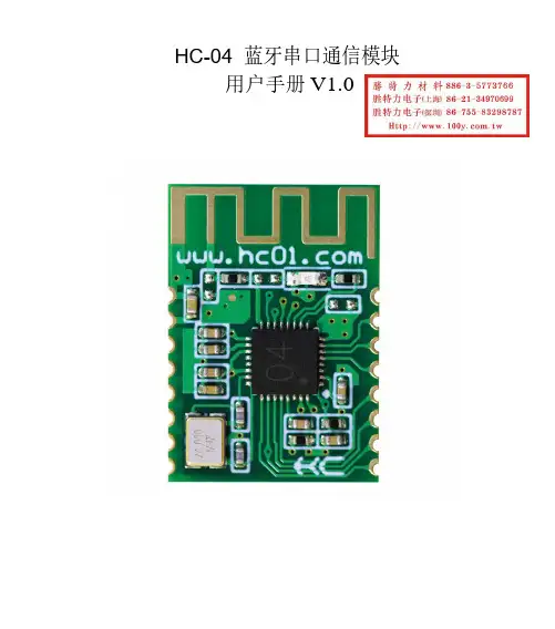
HC-04蓝牙串口通信模块用户手册V1.0软件版本:HC-04V1.0硬件版本:V1.0发布日期2020年03月16日修改记录HC-04蓝牙串口通信模块是新一代的基于V2.1(SPP)经典蓝牙协议和V4.0(BLE)蓝牙协议的双模数传模块。
无线工作频段为2.4GHz ISM,调制方式是GFSK。
模块发射功率为3dBm,接收灵敏度为-90dBm。
模块采用邮票孔封装方式,可贴片焊接,模块大小18.5mm×13mm×2.2mm,很方便客户嵌入应用系统之内。
产品尺寸管脚定义HC-04模块适用于贴片焊接,共有16个引脚,板载PCB天线,引脚具体定义如下表:引脚定义I/O方向说明1GND模块公共地2VCC输入电源脚,要求直流3.3V电源,供电电流不小于200mA 3TXD输出UART输出口,3.3V TTL电平4RXD输入,弱上拉UART输入口,3.3V TTL电平5NC悬空6NC悬空7NC悬空8NC悬空9PB1输出模块连线指示,连线前为高电平,连线后输出低电平。
10PB2输入,下拉AT指令设置脚(注②)11PB3输出模块指示灯输出脚(注①)12PB4输入,弱上拉AT指令设置脚(注③)13NC悬空14NC悬空15NC悬空16RST输入,弱上拉模块复位脚,要求不小于100ms的低电平进行复位注①:模块指示灯输出脚,高电平输出,接LED时请串接电阻。
连线前,LED快闪。
连线后,LED常亮。
注②:输入脚,内部下拉。
在连线状态下,此脚接高电平,可以进入AT指令设置模式;此脚接低电平(或者悬空),返回到串口透传模式。
注③:输入脚,内部弱上拉。
在连线状态下,此脚接低电平,可以进入AT指令设置模式;此脚接高电平(或者悬空),返回到串口透传模式。
电气特性:参数测试条件参考值工作电压-DC3.0V~3.6V工作电流BLE未连接20mA~60mA变化已连接约22mA SPP未连接20mA~60mA变化已连接约30mA模块参数设置AT指令AT指令用来设置模块的参数,模块在未连线状态下可以进行AT指令操作,连线后进入串口透传模式。
HC-42蓝牙5.0BLE串口模块用户手册目录一.模块介绍1.1特点简介 (3)1.2基本参数 (3)1.3电气特性 (3)1.4系列产品 (4)二.连接通讯说明2.1模块工作原理简单介绍 (4)2.2模块MCU等设备的连接通讯 (4)2.3模块与手机的连接通讯 (5)三.快速测试3.1参数架与模块连接 (5)3.2通讯测试 (5)四.开发利用4.1模块尺寸和引脚定义 (6)4.2嵌入方式 (7)4.3参考连接电路 (8)五.AT指令5.1模块参数设置AT指令 (9)5.2指令集总 (9)5.3指令说明 (10)六.关于汇承6.1公司简介 (14)软件版本:HC-42V2.02018-06-18硬件版本:V1.02018-01-12更新内容序号更新内容时间1231.1特点简介HC-42蓝牙串口通信模块是新一代的基于Bluetooth Specification V5.0BLE 蓝牙协议的数传模块。
无线工作频段为2.4GHz ISM ,调制方式是GFSK 。
模块最大发射功率为4dBm ,接收灵敏度-96dBm 。
模块大小26.9mm×13mm×2.0mm ,集成了邮票孔封装,可以贴片工艺,很方便嵌入应用系统之内。
1.2基本参数参数名称参数值参数名称参数值型号HC-42模块尺寸26.9X13mm 工作频段 2.4G 空中速率1Mbps/2Mbps 工作电压 1.8~3.6V 天线接口内置PCB 天线工作电流参照1.3表中所述停机电流0.3μA 通讯接口UART接收灵敏度-96dBm@1Mbps 通信电平 1.8~3.6V ,与工作电压一致工作湿度10%~90%发射功率-40~4dBm存储温度-40℃~+85℃参考距离40m/2Mbps (蓝牙5.0)工作温度-25℃~+75℃1.3电气特性数值备注电压特性1.8V~3.6V 若使用纽扣电池,必须保证电压在2.5V 以上参考电流(不包括LED )1.23mA/1.22mA全速广播/全速连接75μA/65uA 低功耗广播/低功耗连接(工作电流随广播间隔变化)0.3μA停机状态注:以上电流数据是基于气温25℃、工作电压3.3V 、出厂默认配置时测得,实际使用可能存在误差。
蓝牙模块HC05使用说明一、产品概述:蓝牙模块HC05是一款便携式无线通信设备,它可以与其他蓝牙设备(如手机、平板电脑、电脑等)进行无线通信,实现数据的传输和控制。
它采用蓝牙4.0标准,具有快速稳定的无线传输速度和低功耗特性。
本文将介绍HC05的主要功能和使用方法。
二、产品特点:1.蓝牙4.0技术,支持低功耗和高速传输。
2.采用UART串口通信接口,操作简单方便。
3.通信距离可达到10米,适用于近距离无线通信。
4.支持多种蓝牙协议,如SPP、HID、GATT等。
5.低功耗设计,不影响设备的电池寿命。
6.内置蓝牙模块,无需额外连接线路。
三、使用步骤:1.连接硬件将HC05模块插入到设备的UART串口上,并接通供电电源。
确保模块连接正常,并处于待机状态。
2.设置模块参数使用串口调试工具连接到HC05模块的串口,并通过AT命令对模块进行配置。
常用的AT命令有:-AT:检查模块是否正常工作。
-AT+ROLE:设置模块的角色,如主设备或从设备。
-AT+NAME:设置模块的蓝牙名称。
-AT+PIN:设置模块的配对密码。
-AT+BAUD:设置模块的波特率。
-AT+VERSION:查询模块的固件版本。
3.配对蓝牙设备将需要连接的蓝牙设备(如手机)设置为可被到的状态,然后通过手机或其他设备的蓝牙设置界面并选择HC05模块进行配对。
配对成功后,两个设备即可建立蓝牙连接。
4.数据传输和控制通过HC05模块的UART串口与外部设备进行数据的传输和控制。
可以通过串口编程或使用现有的蓝牙通讯协议来实现数据的收发和处理。
5.断开连接和重新连接通过发送AT命令AT+DISC来断开与蓝牙设备的连接。
重新连接时,通过蓝牙设备并选择HC05模块进行再次配对即可。
四、注意事项:1.HC05模块的接口和电源连接正确,避免插反或接反,以防损坏设备。
2.在进行AT命令配置时,注意命令的格式和参数的正确设置,以免出现配置错误。
3.在配对蓝牙设备时,确保设备处于可被到的状态,并选择正确的设备进行配对。
简介Bluetooth™ 蓝牙车载免提HCB-300 设计为可在车内使用,并为在驾驶时拨打或接听电话提供了一种安全而便捷的方式。
在使用车载免提式装置之前,请阅读本用户指南的安全有效使用 和有限担保 部分。
如何使用车载免提式装置?当您拧动点火开关时,车载免提式装置将识别您的手机,并且它们将自动连接。
设备即已就绪,可供拨打和接听电话。
可以将车载免提式装置与多达五台话机一起使用。
车载免提式装置可用于何种话机?可以使用任何启用了蓝牙功能的话机。
本车载免提式装置与索尼爱立信公司(以及,举例来说,诺基亚、摩托罗拉和西门子公司)提供的启用了蓝牙功能的话机兼容。
附件本车载免提式装置支持使用一系列附件,用以增强您的用户体验:• 高级音乐静音装置 HCE-16 - 用于将声音从话机连接到车载音响扬声器。
• 鹅颈式话筒 HCE-14 - 使话筒更靠近您的嘴。
如果将索尼爱立信话机用于车载免提式装置,则可以使用以下附件:• 专用的车载手机座(例如,用于 K700 的 HCH-38 型)以及天线连接线接头 HCE-12,以获得更好的网络接收效果。
• 点烟器适配器 CLA-11 - 用于为话机充电。
操作指南本用户指南中的操作指南基于车载免提式装置按钮和话机按键。
例如,您可以使用车载免提式装置上的按钮或话机上的按键来接听电话。
一些安装工程师。
请参阅第 96页的“安装”。
汉世威c ar co m控制面板概述首次使用首次将车载免提式装置与话机一起使用之前,您需要确保:• 正确安装并开启了车载免提式套装组件。
• 在话机上启用了蓝牙功能。
• 已将车载免提式装置添加到话机中的设备列表。
添加车载免提式装置将车载免提式装置添加到话机中的设备列表后,举例来说,它们将在开启点火开关时自动相互识别。
可为用于车载免提式装置的每台话机选择一个特定的颜色标识。
也可以为特定颜色标识将一台话机替换为另一台话机。
缓慢闪动的颜色标识表示未使用的颜色。
快速闪动的颜色标识表示已在使用的颜色。
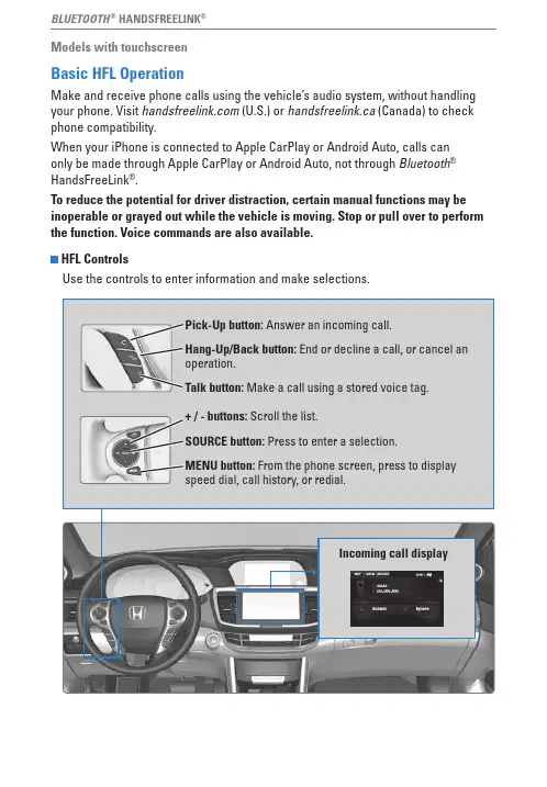
BLUETOOTH® HANDSFREELINK®Models with touchscreenBasic HFL OperationMake and receive phone calls using the vehicle’s audio system, without handling your phone. visit (U.S.) or handsfreelink.ca (Canada) to check phone compatibility.When your iPhone is connected to Apple CarPlay or Android Auto, calls can only be made through Apple CarPlay or Android Auto, not through Bluetooth®HandsFreeLink®.To reduce the potential for driver distraction, certain manual functions may be inoperable or grayed out while the vehicle is moving. Stop or pull over to perform the function. Voice commands are also available.HFL ControlsUse the controls to enter information and make selections.Incoming call displayBLUETOOTH® HANDSFREELINK®Talk Button Tips• When using the Talk button, wait for a beep before saying a command.• To bypass the system prompts, simply press the Talk button again to say your command.• When the Talk button is pressed, all available voice commands are highlighted in yellow.• Speak in a clear, natural voice.• Reduce all background noise.• Close the windows and moonroof.BLUETOOTH® HANDSFREELINK®Models with touchscreenPairing a PhoneTo use hands-free phone and streaming audio functions, you must first pair your phone to the system. This can only be done when the vehicle is stopped. Use the touchscreen to make and enter selections.If there is an active connection to Apple CarPlay or Android Auto, pairing of additional Bluetooth-compatible devices is unavailable and Add Bluetooth Device is grayed out from the Bluetooth Device List screen.1.From the HoMe screen, select Settings.2.Select Phone.3.Select Bluetooth Device List4.Select Add Bluetooth Device.5.oK.6.phone when it appears on the list.If your phone does not appear: Select Phone Not Found and search forHandsFreeLink from your phone.7.when prompted.8.The system asks if you want to enable options:HondaLink Assist: collision notification.Automatic Phone Sync:9.Press BACK to exit the menu.State or local laws may prohibit the operation of handheld electronic devices while operating a vehicle.BLUETOOTH® HANDSFREELINK®Models with touchscreenMaking a CallYou can make a call using several methods.Dialing a NumberEnter a 10-digit phone number to call.Using voice commandsPress the Talk button before you say each command.1.Say “Call by number.”2.Say the phone number. For example,3-1-0-5-5-5-1-2-3-4.”3.The system begins to dial.Using the touchscreenManual operation is limited while the vehicle is moving. voice commands are always available.1.From the HoMe screen, select Phone.2.Select MeNU.3.Select Dial.4.Enter the phone number. Select the green phone icon to call.Storing Speed Dial EntriesStore up to 20 numbers for quick dialing. 1.From the HoMe screen, select Phone.2.Select MeNU.3.Select Speed Dial, then select New entry.4.Select an entry method.5.If desired, you can create a voice tag for thenumber. Follow the prompts.BLUETOOTH® HANDSFREELINK®Using Speed Dial and Call HistoryMake calls quickly using stored speed dial entries or call history numbers. Using voice commandsPress the Talk button before you say each command.1.Say “Dial by name.”2.Say the stored voice tag name. For example,“John Smith.”Using the touchscreen1. From the Home screen, select Phone.2. Scroll through the list to find the entry you wantto call, and select it to call.Using the PhonebookWhen your phone is paired, its entire phonebook can be automatically imported to the system. Automatic Phone Sync must be turned on.Using voice commandsPress the Talk button before you say each command.1. Say “Call by name.”2. Say the phonebook name and phone type. Forexample, “John Smith mobile.”Using the touchscreenManual operation is limited while the vehicle is moving. voice commands are always available.1.From the HoMe screen, select Phone.2.Select MeNU.3.Select Phonebook.4.Scroll through the list to find the name andnumber you want to call, and select it to call.。
蓝牙使用说明范文蓝牙是一种无线通信技术,可以将不同设备之间进行连接和传输数据。
它是一种短距离通信技术,通常在10米内进行操作。
蓝牙技术的发明是为了取代有线连接的方式,使设备之间更加方便地进行数据传输。
通过蓝牙,可以实现手机与耳机、电视与音响、电脑与键盘鼠标等设备之间的无线连接。
蓝牙的使用非常简便,只需遵循以下步骤即可实现设备之间的连接。
第一步,打开蓝牙功能。
在手机或电脑等设备的设置中,找到蓝牙选项,并打开蓝牙功能。
有些设备可能需要将蓝牙功能设置为可见,才能被其他设备检测到。
第二步,其他设备。
在设备的蓝牙设置中,点击附近的蓝牙设备。
通常设备会自动并显示附近的蓝牙设备。
第三步,选择要连接的设备。
从到的设备列表中选择要连接的设备。
通常设备会有一个名称或者编号,以便于区分。
第四步,配对两台设备。
在选择要连接的设备后,会弹出一个配对码或验证对话框。
两台设备需要输入相同的配对码或者进行验证,才能实现连接。
第五步,连接设备。
在完成配对后,两台设备即可建立连接。
连接后,可以进行数据传输、音频播放等操作。
蓝牙连接可能会有一些常见的问题和解决方法。
首先,连接失败。
连接失败可能是由于设备不在蓝牙范围内,或者设备没有开启蓝牙功能。
解决方法是将设备靠近一些,确保蓝牙功能已打开。
其次,连接断开。
连接断开可能是由于设备离得太远,或者有其他设备干扰。
解决方法是将设备靠近一些,或者去除干扰源。
再次,信号质量差。
信号质量可能会受到物理障碍物、设备质量等因素影响,导致传输质量较差。
解决方法是将设备靠近一些,或者增强信号的接收和发送能力。
总结起来,蓝牙的使用非常简单,只需通过几个步骤即可实现设备之间的连接。
蓝牙技术的发展使得设备之间的无线连接更加便捷,为用户提供了更多的便利。
通过蓝牙,我们可以实现手机和其他设备之间的连接,使得数据传输、音频播放等操作更加方便。
同时,我们也需要注意蓝牙连接可能会出现的问题,并通过相应的方法解决。
蓝牙技术将继续发展,为我们的生活带来更多的便利。
捷用hc5000说明书
1、调时间:长按设置键等旁边锁头样打开后放开,再按一次设置键,时间的时闪烁,再按上下键调整完成后按设置键保存完成。
2、设定自动开灯时间的3个时段:还是在锁头标打开时,长按照明时段键待上面第一时段ON闪烁,随即连续短按上下键调整开灯开始时间。
完成后再短按照明时段键于是OFF闪烁再同样调整,依次调整3段开灯关灯时间后最后按照明时段键完成。
3、手动自动,和手自动调整:同样长按设置开锁,短按设置选择手动自动,当自动显示时再按一下照明时段键即可变为手自动,及手动触摸也能开灯,延时关灯变为自动模式。
蓝牙模块HC使用说明一、硬件连接1.准备工作:将HC模块的VCC引脚连接到正电源,GND引脚连接到地线,TX引脚连接到微控制器的RX引脚,RX引脚连接到微控制器的TX引脚。
2. 配置参数:检查微控制器的串口波特率设置,确保与 HC 模块的波特率一致。
默认波特率为 9600bps,可以通过 AT 命令修改。
3.电源供应:为HC模块提供正常的电源供应,电压范围为 3.6V-6V。
请注意,提供过高或过低的电压会导致模块无法正常工作。
二、软件设置1. 初始化串口:在微控制器的代码中,使用适当的函数初始化串口,并确保波特率与 HC 模块一致。
例如,在 C 语言中,可以使用uart_init( 函数进行初始化。
2.AT命令:HC模块通过AT命令进行配置和通信。
通过在串口上发送AT命令,可以更改蓝牙模块的参数,例如名称、波特率等。
常用的AT命令包括:-AT:检测HC模块是否正常工作,模块将返回"OK"。
-AT+NAME:设置HC模块的名称。
-AT+BAUD:设置HC模块的波特率。
通过发送AT命令,可以自定义HC模块的参数,以适应特定的应用场景。
3. 数据传输:使用 HC 模块进行数据传输需要编写相应的代码。
首先,将需要传输的数据发送到 HC 模块的串口。
然后,使用适当的方法从HC 模块接收数据。
例如,在 C 语言中,可以使用 uart_send( 函数将数据发送到 HC 模块,并使用 uart_receive( 函数从 HC 模块接收数据。
三、注意事项1.波特率一致:在使用HC模块之前,请确保HC模块和微控制器的波特率一致,否则无法正常通信。
2.电源供应稳定:为HC模块提供稳定的电源供应,电压范围在3.6V-6V,以确保模块正常工作。
3.AT命令应用:通过发送AT命令,可以根据需要自定义HC模块的参数。
这样可以使HC模块更适配于特定的应用场景。
4.距离限制:蓝牙信号传输距离有限,通常约为10米。
BLUETOOTH® HANDSFREELINK® (HFL) BLUETOOTH® HANDSFREELINK® (HFL)Learn how to operate the vehicle’s hands-free calling system.Basic HFL OperationMake and receive phone calls using the vehicle’s audio system, without handling your phone. Visit (US) to check phone compatibility. Canada customers can phone (855)-490-7351 for any HandsFreeLink® related inquiry.To reduce the potential for driver distraction, certain manual functions may be inoperable or grayed out while the vehicle is moving. Voice commands are always available.n HFL Displays and ControlsUse the controls to enter information and make selections.Pick-up button:Press to go directly to the phone menu on the driver information interface, or to answer an incoming call.Hang-up/back button:Press to end a call, go back to the previous command,or cancel a command.Talk button:Press to access Voice Portal.Up/Down buttons:Press to select an item displayed on the phone menu in the Driver Information Interface.ENTER button:Press to call a number listed in the selected item on the phone menu in the Driver Information Interface.Display/Information button:Select the Phone button and press ENTER to display Speed Dial, Call History, or Phonebook on the phone menu in the Driver Information Interface.n Talk Button TipsWhen using the Talk button, wait for the beep before saying a command.The system recognizes commands listed in the Voice Command Index.•When using the Talk button, wait until you hear a beep before speaking.•To bypass the system prompts, simply press the Talk button again to say your command.•Speak in a clear, natural voice.•Reduce all background noise.•Adjust the dashboard vents away from the microphone on the ceiling.•Close the windows and moonroof *1.BLUETOOTH ® HANDSFREELINK ® (HFL)Models with Display AudioPairing a PhoneTo use hands-free phone and streaming audio functions, you must first pair your phone to the system. This can only be done when the vehicle is stopped. If there is an active connection to Apple CarPlay ™ (see Apple CarPlay) or Android Auto ™ (see Android Auto), pairing of additional Bluetooth-compatible devices is unavailable and Add Bluetooth Device is grayed out from the Bluetooth Device List screen.n Pairing the First PhoneModels with Display AudioUse the touchscreen to make and enter selections.BLUETOOTH ® HANDSFREELINK ® (HFL)1.Select Phone.2.Select Yes.3.Make sure your phone is in search or discoverable mode, then select Continue.HFL automatically searches for a Bluetooth ® device.4.Select your phone when it appears on the list.If your phone does not appear, you can select Refresh to search again.If your phone still does not appear,select Phone Not Found and search for Bluetooth ® devices using your phone. From your phone, search for HandsFreeLink ®.5.The system gives you a pairing code on the audio/information screen.Confirm if the pairing code on the screen and your phone match. Thismay vary by phone.Making a CallYou can make calls by inputting any phone number, or by using the imported phonebook, call history, speed dial entries, or redial.n Dialing a NumberModels with Display AudioApplicable laws may prohibit the operation of handheld electronic devices while operating a vehicle.BLUETOOTH ® HANDSFREELINK ® (HFL)1.Go to the Phone Menu screen.2.Select Dial.3.Select a number.Use the keyboard on the touch screen for entering numbers.4.Select the Phone button.Dialing starts automatically.n Using the PhonebookWhen your phone is paired, its phonebook is automatically imported to the system.This method is inoperable while the vehicle is moving.Models with Display Audio1.Go to the Phone Menu screen.2.Select Phonebook.3.Select a name.You can also search by letter. SelectSearch.Use the keyboard on the touch screenfor entering a name, if multiplenumbers exist select a number.4.Select a number.Dialing starts automatically.n Storing Speed Dial EntriesStore up to 20 numbers for quick dialing. To store a speed dial number:Models with Display Audio1.Go to the Phone Menu screen.2.Select Speed Dial.3.Select New Entry.From Import from Call History:Select a number from the call history.From Manual Input:Input the number manually.From Import from Phonebook:Select a number from the connected cell phone’s imported phonebook.4.When the speed dial is successfullystored, you are asked to create a voicetag for the number. Select Yes or No. 5.Select Record, or use Talk button andfollow the prompts to complete the voice tag.BLUETOOTH® HANDSFREELINK® (HFL)n Using Speed DialMake calls quickly using stored speed dial entries or call history numbers.Models with Display Audio1.Go to the Phone Menu screen. Array2.Select Speed Dial.3.Select a number.Dialing starts automatically.。
吾爱woowi蓝牙耳机BTHC010说明书蓝牙无线通信技术介绍蓝牙是一种近距离无线通信技术规范。
通过蓝牙技术,可以在手机、电脑、打印机、PDA 等电脑数码设备之间实现高速,传输距离为10米的无线数据通讯。
使用之前一、产品概览1:上一曲 2:多功能键 3:下一曲 4 状态指示灯 5 头戴 6 可伸缩和折叠的头戴 7 右扬声器8 左扬声器 9 麦克风10 Micro USB :充电 11 音量 + :增大音量 12 音量 - :减小音量二、给耳机充电耳机使用内置可充电电池,首次使用耳机前必须给电池充满电。
有如下两种充电方式:警告:为本产品提供电源的可充电电池必须妥善处置,以便回收利用。
请与当地的回收中心联系来获取妥善处置的办法。
不要将电池放入火中,以免引起爆炸。
使用耳机一、配对、打开、关闭耳机注意:△配对模式会维持2分钟,超过2分钟仍未与任何设备配对,耳机会自动切换到待机模式;△若开机后5分钟仍未连接到任何设备,耳机会自动关机,以节省电量。
二、与蓝牙手机配对(与其他产品配对方式请参考下面“相关应用”)首先请确保您的手机具备蓝牙功能并且是可用的。
具体配对过程可能因手机而异,详细情况请阅读您的手机说明书中关于蓝牙设备配对的指引。
配对步骤如下:1.把手机与耳机的距离保持在1米以内;2.令耳机进入配对模式(参照上面“配对模式”);3.开启手机蓝牙功能,搜索蓝牙设备。
当搜索完毕后,在显示的设备列表中选择“WooWiBTHC010”;4.根据手机提示按‘是’或‘确认’键确认,配对成功;5.连接成功后,耳机蓝灯每隔四秒快闪两次。
注意:△配对成功之后,配对设备会相互记住对方,下次使用时无需重新配对;△蓝牙版本低于V2.1的手机会提示输入密匙或PIN码: “0000”。
三、佩戴耳机本耳机的头戴采用可伸缩可折叠式设计,佩戴时请根据实际使用情况将耳机头戴调节至合适的长度,并按照耳机上的标识‘L’对应左耳,标识‘R’对应右耳,根据相应指示将耳机佩戴至头上。