HVM过滤器用户手册_非自流_No[1].2-17
- 格式:pdf
- 大小:597.13 KB
- 文档页数:43

Instrumentation and Gas Sampling FiltersBulletin 1300 - 694/USA Finite®Stainless steel, aluminum & plastic housings Clear bowls availableConnections from 1/8” to 2” NPTPressures to 5000 PSIG••••1. Evaluate the requirements of your application. The sketches on page 49 depict popular Examples of gas sampling, process filtration, instrument air and breathing air applications.2. What type of filtration is needed? (See pages 50-51) Coalescing filter medias remove solid and liquidcontaminants from gas streams. Particulate filter media removes solids from gas streams. Adsorber media removes hydrocarbon vapors from gas streams.3. Are you searching for a specific micron rating ... or efficiency rating? If so, page 51 provides a complete breakdown of Finite ’s filter media grades and their performance specifications.4. What are the operating conditions of your application? Key criteria to consider: flow, pressure, materials of construction ... stainless steel, nylon, aluminum, etc. Pages 52-58 provide detailed descriptions of the various products available.5. Sizing - The flow chart on pages 59-60 lists the flow rates (SCFM) at various operating pressures.Filters are available with flows up to 3366 SCFM and pressure ratings up to 5000 PSIG.Finite ®Instrumentation and Gas Sampling FiltersThe following steps will help you to choose the correct filter for your application. If there are other factors involved or if you have special requirements, call Finite ’s technical support.Finite ’s instrumentation and point-of-use product line offers compressed air/gas filtration solutions for food processing, medical, chemical processing, and compressed natural gas applications. Typicalinstallations includecontaminant removal for breathing air, protection of gas analyzers and prefilters for instrument air dryers.Our UNI-CAST element technology allows us tovacuum form high-efficiency particulate and coalescing filter elements. Our elements are designed with high voidvolumes to provide longer element life while yielding lower pressure drops.Made directly from the highest quality microglass fibers available, Finite ’selements are constructed in 5 porosity grades and 9 media types to meet nearly all compressed air/gas applications.Finite ’s instrumentation filter housings are carefully engineered to meet critical application specifications. A complete line of stainless steel housings are available with a variety of pressure ratingsand flows for corrosive applications.Combination aluminumhead/nylon bowl assemblies are offered for lower operating pressures and temperatures, while disposable plastic in-lines are offered for low flow and OEM applications. If you have a specific need or are unable to find the compressed air/gas filter your application requires, call us!Let one of Finite ’sapplication engineers assist you! Visit us on the web at /finitefilter or call us toll-free1-800-521-4357 and ask for technical support.Instrumentation and steam filterFinite ®Instrumentation ApplicationsMedia Grades:Grade 6 filter elements are used when “total removal of liquid aerosols and suspended fines” is required. Because of its overall performance characteristics, this grade is most often recommended below 500 PSIG.Grade 4 filter elements are very high efficiency coalescers; for elevated pressures or lighter weight gases. Recommended when system pressure exceeds 500 PSIG.Grade 7CVP filter elements are made with two layers. The inner layer (left) effectively traps dirt particles, protecting and extending the life of the outer layer. The coalescing outer layer (right) consists of a dense matrix of glass fibers, providing highly efficient aerosol removal.Grade 10 filters are used as prefilters for grade 6 to remove gross amounts of aerosols or tenacious aerosols which are difficult to drain. This grade is often used as a ‘coarse’ coalescer.Grade 8 filter elements provide high efficiency filtration in combination with high flow rate and long element life.Grade 4Grade 6500X500XGrade 7CVP Grade 8Grade 10500X500X500XGrade 3P125X125X Three micron pleatedcellulose filters areG T FG T F HCR46810Media Grade A = Aluminum IL15 = 1/8” NPT 1= 1/4” NPTMedia Type S = 316 Stainless SteelApplication: Finite ’s high pressure filters are available with housings made of 316 stainless steel (S5R,S1R) or aluminum (A5R, A1R). This series is used for gas bypass sampling, high pressure compressed natural gas filtration, and applications with elevated pressures and corrosion resistance requirements. High efficiency particulate and coalescing elements are available with these units. Includes drain port with plug. Connection size of drain port matches inlet and outlet connection size.specifications:Application: The S1IL filter is typically applied for the particulate filtration of bottled gas or as a last chance filter where there is limited space availability. It does not have a drain port and should only be used when little or no liquid contaminant is expected.How to Order:Materials Port Size 04-023For Example: S1R-6C04-023 for complete assembly, including element. S1R X 1 for an empty housing.Media Type Media Grade 4681004-013How to Order:For Example: S1IL-8T04-013 for complete assembly, including element. S1IL X 1 for an empty housing.Element SizeElement SizeSInstrumentation and steam filterG T F HS = Short L = LongS = Short L = LongG T F Hspecifications:Application: These filters are used for gas analyzer protection andcorrosive applications where element visibility is required. These housings have smaller internal volumes which allow for quicker evacuation and fastersampling times. Includes 1/4” NPT drain port with plug.MediaType Media Grade 46810How to Order:Port Size 10-070 = longFor Example: S1PL-10T10-070 for complete assembly, including element. S1PL X 1 for an empty housing.Bowl Length Element Size10-025 = short bowl 1 = 1/4” NPT 2 = 1/2” NPTApplication: These filters have similar applications as filter above, however this version has a stainless steel bowl which allows for higher pressure and temperature applications. Includes 1/4” NPT drain port with plug.1 = 1/4” NPT 2 = 1/2” NPTMedia Type Media Grade 46810How to Order:Port Size 10-070 = longFor Example: S2SS-10G10-025 for complete assembly, including element. S2SS X 1 for an empty housing.Bowl Length Element Size10-025 = short bowl SSPSApplication: Finite ’s 2” NPT stainless steel filter is theright solution for most critical or corrosive compressed air/gas applications. Its 500 PSIG design pressure makes this an ideal choice for higher pressure applications. Bulk liquid separating,coalescing, particulate and adsorptive filters are available. Includes 1/4” NPT drain port with plug. Application: Finite ’s S3C and S4C units are economical stainless steel filter assemblies for applications in food processing, pharma -ceutical, and chemical manufacturing. Coalescing, particulate andadsorptive filters are available. Includes 1/4” NPT drain port with plug.specifications:S3C - 4.28”/108.71 mmS4C - 4.44”/112.78 mmHow to Order:For Example: SN8S X 1Elements sold separately: *CU, 3PU, AU, 7CVP and 100WS (Bulk Liquid Separator) Element size is 24-187. * insert grade: 4, 6, 8, 10Media Gradeblank for 3PU, AU 46810CU 3PU AUHow to Order:Port Size For Example: S3C-6CU13-087 for complete assembly, including element. S3C X 1 for an empty housing.Media Type 3 = 3/4” NPT 4 = 1” NPT13-087For Example: 6CU24-187 X 1Element SizeSCSN8S1XInstrumentation and steam filterMedia Gradeblank for AM 46810HMAMMedia Type 5 = 1/8” NPT 1 = 1/4” NPT06-013Port Size Application: The Q1S, Q5S series filters are an excellent choice forinstrumentation and point-of-use general air system filtration. They also provide coalescing and adsorption filtration for robotic and OEM machine manufacturers. Amanual twist drain is standard. An auto drain option is available.Application: These aluminum filters are an excellent choice for instrumentation and point-of-use general air system filtration. The zinc bowl is preferred inhigher temperature and pressure applications. They also provide coalescing and adsorption filtration for robotic and OEM machine manufacturers. A manual twist drain is standard. An auto drain option is available. How to Order:For Example: Q1S-AM06-013 for complete assembly, including element.Q1S X 1 for an empty housing.How to Order:For Example: H5S-6HM06-013 for complete assembly, including element.H5S X 1 for an empty housing.specifications:Element Sizeblank for manual twist drainA = Auto DrainF = 1/8” ID Hose Barb V = Needle ValveDrain OptionPort Size Element SizeMedia Gradeblank for AM 46810HMAMMedia Type 5 = 1/8” NPT 1 = 1/4” NPT06-013blank for manual twist drainA = Auto DrainF = 1/8” ID Hose Barb V = Needle ValveDrain OptionQSHSGT F H C CU QU 3PU AUG T F H C75PApplication: KN1S and KN5S filters are an economical way to providehigh-efficiency filtration for protection of emission analyzers, air-logic systems and low-flow point-of-use pneumatic components. Includes manual, tee-valve drain. (1/8” NPT port)114.3 mmApplication: The P1N offers economical high efficiencyfiltration for point-of-use, instrument systems or OEM circuit protection. The P1N is also used when sump and element visibility are required. Includes manual twist drain. Media Gradeblank for 75P 46810How to Order:For Example: KN1S-6C06-016 for complete assembly, including element. KN1S X 1 for an empty housing.Media Type 5 = 1/8” NPT 1 = 1/4” NPT06-016Port Size MediaGradeLeave blank for 3PU and AU46810How to Order:For Example: P1N-4QU10-025 for complete assembly, including element. P1N X 1 for an empty housing.Media Type 10-025specifications:Element Size Element SizeNote: The 75P Media Type is a 75 micron plastic filter element.PN1KN1Instrumentation and steam filterG T F Hblank forno drain; closed D = Open;constant bleed drainV = Valved;manual drainG T F H C CU QU3PUAUApplication: The ILN, IKN in-lines are used for low flow circuit protection on sensing instruments, analyzers, air-logic, and other control devices.High-efficiency coalescing and particulate elements are available. Drain types available include manual push, constant bleed or no drain.The design: This twist-lock plastic housing is designed for 50 PSIG Maximum operating pressure. The two-stage filter design allows for high efficiency ele -ment replacement and the reuse of the 74 micron prefilter (74P05-011 X 10).Application: The QN series is an excellent point-of-use filter when element visibility is required. Coalescing, particulate and adsorption elements available. Includes plastic manual twist drain.specifications:Media Gradeblank for 3PU, AU 46810How to Order:For Example: Q N15N-10QUN for complete assembly, including element. QN15NN X 1 for an empty housing.Media Type 1 = 1/4” NPT 15 = 3/8” NPT 2 = 1/2” NPTPort Size AccessoriesN = NoneD = Differential Pressure Indicator G = Differential Pressure GaugeMedia Grade 46810How to Order:For Example: IKND-4G05-011 for complete assembly, including element. IKND X 1 for an empty housing.Media Type L = 1/8” NPT K = 1/8” NPT with brass inserts05-011Port Size Type of Drain Element SizeNote: Although the element size is not included in the part number construction for this filter, the size, 10-025, is needed to order replacement elements. For Example, 6C10-025 X 8.QNNINMedia TypeAvailable for ID only44P = 44 micron SS mesh Available for MD only 5P = 5 micron SS mesh Available for ID/MD G = Epoxy T = PTFEF = FluorocarbonAvailable for SD only A = Activated Carbon J = Silica GelM = Molecular Sieve O = Oil Activated Dye4A = 1/8” Right Angle BarbsApplication: These high-efficiency, disposable in-line filters are great for analyzer and sensor protection, gas sampling, micro-system operation and robot and animation air preparation. This clear, nylon housing allows visible inspection of collected particulate. The full length internal tube support gives higher strength, even with system upsets.The Type ID enclosure in conjunction with a ‘G’, ‘T’ , ‘F’ or ‘44P’ series element is designed toprovide the most reliable, long lived, instrument air source, sensor protection, sample cleansing and purification available today. The center core provides stable backup support, reduces internal (tare) volume, centers the tube in the housing and distributes the contaminant load along the tube’s entire length. Elements in the housing are sealed by a positive serrated arrangement with built-in redundancy, ultrasonically welded.The Type MD housing in conjunction with a ‘G’, ‘T’, ‘F’ or ‘5P’ element is designed to provide a high reliability instrument air source or sensor protection where some levels of condensed moisture or oil are present. A stand-pipe is molded into the lower housing to allow for a dry exit chamber as liquids collect at the tube base. Up to 3cc of liquid can be stored in this manner. The same tube size is employed as in the Type ID. Typical applications involve high condensate conditions such as vacuum or highertemperature systems.Type MD In-line filtersFor critical point-of-use, vapor free instrument or medical systems the Type SD provides Maximum activated surface exposure to the process gas while pre-filtering with grade 10 pads and preventing media migration with exit safety filters.Adsorbing Media AvailableType A: Activated carbon for general use oil vapor removal.Type J: Silica gel moisture trap dries gas, turns white when expended.Type M: 13X molecular sieve for selective polishing and ‘last trace’ light hydrocarbon vapor removal.Type O: Activated dye turns red when exposed to oil in system.Type SD In-line filters4S = 1/8” Straight Barbsspecifications:How to Order:For Example: IDN-6G for complete assembly, including element.Type Tang LengthN = LongS = ShortEndConnectionsblank = Standard Tangs (1/4” outer diameter) 4S = 1/8” Straight Barbs 4A = 1/8” Right Angle BarbsType ID In-line filtersMedia GradeLeave blank for SD,5P,44P 46810Standard 1/4” O.D. Tangs ID MD SDInstrumentation and steam filter。
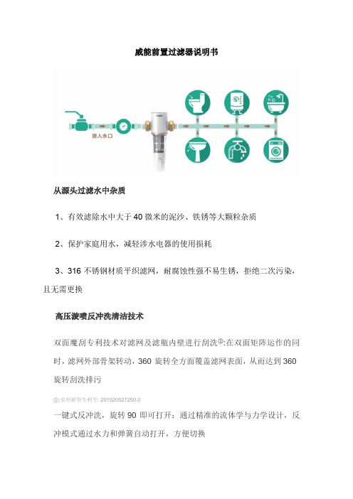
威能前置过滤器说明书
从源头过滤水中杂质
1、有效滤除水中大于40微米的泥沙、铁锈等大颗粒杂质
2、保护家庭用水,减轻涉水电器的使用损耗
3、316不锈钢材质平织滤网,耐腐蚀性强不易生锈,拒绝二次污染,且无需更换
高压漩喷反冲洗清洁技术
双面魔刮专利技术对滤网及滤瓶内壁进行刮洗①:在双面矩阵运作的同时,滤网外部骨架转动,360°旋转全方面覆盖滤网表面,从而达到360°旋转刮洗排污
①:实用新型专利号: 201520527250.0
一键式反冲洗,旋转90°即可打开:通过精准的流体学与力学设计,反冲模式通过水力和弹簧自动打开,方便切换
4吨大流量,轻松满足全家高峰用水
4吨/小时相当于66.7L/min流量出水,可以满足一个家庭同时4个浴缸龙头同时出水②
②:理论估算,以国标12L/min的上限值测算
坚固耐用不漏水,耐压防爆安全可靠
1、加厚防爆瓶,不含BPA,保证用水安全③
2、无惧严苛冰冻测试,-30③防冻裂(北方地区建议室内安装)③
3、通过15万次水锤冲击(12公斤水锤测试)③
4、每平方英寸可承受870psi压力(60kg/c㎡),无渗漏爆裂③。

TABLE OF CONTENTS INTRODUCTION (2)INSTALLATION (3)Setup (3)Enclosure Assembly for Stand Alone Final Filters (6)Door Installation (6)Enclosure Anchoring (7)Ducting a Stand Alone Final Filter (7)Filter Cartridge Installation (8)Cartridge Support Installation (9)Compressed Air Supply (10)Electrical Connections (10)The Wiring Process (10)Choosing the Correct Wiring Procedure (11)Wiring from the Timer Board to the Solenoid (11)Photohelic Connections (11)Initial Checks (12)OPERATION (13)Electrical Settings (13)Solenoid Sequence Setup (13)Selector and Push Button Switch Operation (13)Startup (13)MAINTENANCE (15)Periodic Maintenance Schedule (15)Filter Cartridge Replacement (15)SPARE PARTS LISTING (17)INTRODUCTIONThe Osprey Final Filter is designed to enhance the filtering capacity of the Osprey Drum Filter or Phoenix TM Filter System. The purpose is to filter fine particulate material from an air stream. The filter cartridges remove 99.95% of particulate matter down to 1 micron. Clean air can be exhausted into manufacturing plant, atmosphere, or temperature control system.The Final Filter uses a long lasting, fiber resistant cartridge design. This allows easy installation, low maintenance, and automatic pulsejet cleaning.This manual was written for the Osprey Final Filter and is applicable to all sizes of the Osprey Final Filter. Drawings in this manual apply to the base model unless otherwise noted.This manual is divided into five sections:1) Introduction2) Installation and Start-up3) Operation4) Maintenance5) Spare Parts ListingSafety information and information of special note are included throughout the manual. Four different types of notes are used in this manual and appear as shown.is used to prevent personnel injury.-WARNING-is used to prevent personnel injury.is used to prevent machine damage.-CAUTION-is used to prevent machine damage.is used to show information that is necessary to insure proper installationmation that is necessary to insure proper installation -IMPORTANT-is used to show inforand operation.and operation.is used to provide information of special interest.-NOTE-is used to provide information of special interest.INSTALLATIONSetupFirst, check the crates shipped against the shipping list to identify missing or damaged parts. Follow the instructions in the bulletin titled “What to do if your shipment is damaged, lost, or stolen!” located in the Osprey job manual shipped with the equipment, if applicable. If all is well, uncrate the Final Filter and gather the parts near, but not on, the planned erection site. Before beginning installation, go over the assembly drawings (included in the Osprey job manual shipped with the equipment) to become familiar with the components that will require assembly. Also, read the Drum Filter (or Phoenix TM Filter) Installation and Operation Manual completely. Install the drum filter and begin installation of the enclosure before installing the Final Filter. Assembly of the Final Filter section is best done while installing the drum filter enclosure. Use Figure 1 and the assembly drawings specific to your equipment (included in the Osprey job manual) as a guide throughout this installation. If you have purchased a stand alone Final Filter, assemble the filter enclosure following the section labeled “Enclosure Assembly for Stand Alone Final Filters”.Assemble the drum enclosure except for the roof and front wall where the main system fan isFigure 1 Osprey Final Filter overall layout.Assemble the tubesheet panels intheir proper placein the samemanner as theenclosure wallpanels wereinstalled. Also,install the tubesheet-flashingpanel at this time.Be sure to placesilicone (includedin shipment)between allmating panelflanges.See Figures 2 and3 for examples.Figure 2 Assembled tube sheet panels and tube sheet flashing, as viewed through the drum plenum wall.Figure 3 Assembled tube sheet panels and tube sheet flashing from a stand alone Final Filter.Figure 4 Manifolds installed on manifold mounts.Bolt on the enclosure roof panels at this time. This will steady the tube sheet panels for the rest of the installation.Bolt the manifold mounts into their proper position, aligning the holes on its flange with the row of holes down the center of the tube sheet panels. Use 3/8"-16 wiz bolts and nuts to bolt it.Locate the manifold mount braces and bolt them to the tube sheet panels and to the manifold mounts using 3/8"-16 wiz bolts and nuts.Now, find the air manifolds. The air manifolds come preassembled with the diaphragm valves, solenoid valves, and air hoses. Secure them to the manifold mount braces installed earlier using 3/8"-16 x 1 1/4" bolts, 3/8" washers and lock washers, and 3/8"-16 nuts.When the manifolds are installed, install the manifold stiffeners. These keep movement and vibration of the manifolds to a minimum when the diaphragm valves are activated and the filter cartridges are pulse cleaned.-NOTE- Hardware may differ for someassemblies. Check the assemblydrawings shipped with theequipment for proper mountinghardware.hardware.-WARNING-Do not damage Do not damagethe air hoses the air hoseswhen installing when installingthe manifolds the manifoldsand manifold and manifoldstiffeners.stiffeners.Figure 4 shows an installation of the tubesheet panels, manifold mounts and brackets,the manifolds, and the manifold stiffeners.-NOTE-Act Actual assemblies may ual assemblies may ual assemblies maydiffer from figures differ from figuresused in this manual. used in this manual.Consult the assembly Consult the assemblydrawings shipped with drawings shipped withthe equipment for the equipment for details.details.Figure 5 Stand Alone Final Filter Enclosure (partiallyassembled).Enclosure Assembly for Stand Alone Final FiltersDetermine component/equipment arrangement and establish critical locations for major items and mark on floor in appropriate manner (chalk line). Consult customer and/or Osprey drawings for details (Footprint drawings are available from Osprey).-IMPORTANT- Some panels are not interchangeable. Compare the tags located on the top ofeach panel with the enclosure assembly drawing(s) included in the blue jobmanual shipped with the equipment.Assemble the front wall by first laying two panels on the ground and putting a bead of silicone (supplied by Osprey) on the end flanges of the two mating wall panels to ensure an airtight seal. Bolt the two flanges together using 3/8"-16 wiz nut and bolts supplied with the equipment. When the wall is assembled, raise it into place keeping it aligned with the mark that was make on the floor earlier. Anchor the wall to the foundation by drilling through every other hole in the bottom flanges of each panel and securing with an appropriate fastener (not supplied by Osprey). Figures 2 and 5 show a stand-alone Final Filter being assembled.together. In addition, the enclosure panels must level and plumb to insure proper fit, so shim necessary.-NOTE- Do not anchor these panels to foundation at this time. assembly is complete.wall panels are installed to ease installation.Door InstallationSilicone ends of wall panels making up door opening.Place preassembled door and frame in the panel openingand secure in place. Match drill all four corners of doorand frame assembly with the enclosure panel flanges andbolt in place utilizing the standard hardware kit.Figure 6 Door installation.Figure 7 Ducting to an Osprey Stand Alone Final Filter.Enclosure AnchoringWhen all the enclosure panels and doors are in place, tighten all screws holding enclosure panels together. Install any bolts not present in wall panels and roof panels. Check enclosure to make sure it is level and square. Shim where necessary by using wood or metal shims of appropriate thickness. Anchor enclosure to floor by drilling through holes in bottom flange of wall panels. Typical anchors used are 3/8" x 3" bolts or studs for concrete floors, 3/8" x 3" lag bolts for wooden floors or 3/8" hex bolts with nuts for steel plate or drilled and tapped holes. These items are not furnished by Osprey. These fasteners must be furnished by others or by Osprey at additional expense with prior notification of mounting surface specifications.Ducting a Stand Alone Final FilterStand Alone Final Filters may come with flanges or attachment points for ducting specified by the customer. If this is the case, attaching ducts to the Final Filter enclosure is as simple as aligning the duct flange with the corresponding flange on the enclosure then bolt the two together.If no attachment points are present, holes may be cut in the enclosure wall panels and roof panels to bolt ducting to the filter. Avoid directing airflow directly into a filter cartridge as this may reduce the life of the cartridge. Place ducting so air flow is parallel with the direction of the filter cartridges.All ducts must be properly supported by means other than the bolts holding them to the Final Filter enclosure (Figure 7). Please read the “Design Standards for Ducting Osprey Equipment” paper located in the Osprey job manual. This paper gives guidelines for material and size of ducts in relation to air flow volume and velocity.Filter Cartridge InstallationThe number of filter cartridges included with each Osprey Final Filter is determined by the volume of air passing through the filter and the speed of the airflow. There may be just a single cartridge for each opening in the tube sheet panels, or two cartridges may be installed end to end to provide desirable air flow characteristics.In each case, install the cartridges starting at the top of the tube sheet panel. Work across and then down to provide best access.Figure 8 illustrates the installation of a single cartridge. The parts needed for this are:1. Filter cartridge2. Single length crank3. Metal backed rubber washer4. Filter cartridge end cap5. ½ "-13 square nut6. ½ "-13 jam nutFirst, place the end cap on the end of the filter cartridge (not the end with the rubber seal). Slide the rubber washer on the crank, metal side first. This will ensure an airtight seal between the washer and the cartridge end cap.Put the straight end of the crank through the hole in the cartridge end cap, through the cartridge, then into the hole located in the tube sheet panel. Put the jam nut and square on the end of the crank handle. Turn the crank handle to secure the filter cartridges to the tube sheet panel.-IMPORTANT-Do not over tighten the crank handles, as it may cause damage to the seal.Figure 8 Single filter cartridge installation.Double cartridge installation is similar to the single cartridge installation. The only differences are that there are two cartridges on a longer crank, with a spider in between the cartridges for support. Figure 9 illustrates this.Figure 9 Double filter cartridge installation.Cartridge Support InstallationSome Osprey Final Filters come with a support structure for the filter cartridges. Installation of this support assembly is straightforward. Bolt the cross arms to the vertical support, and place this behind the filter cartridges so that the cranks holding the cartridges in place rest in the slots in the cross arm. When in place, drill holes through the bottom feet of the vertical supports into the foundation. Anchor into place with fasteners suitable for the foundation material. Drill holes through the top feet into the roof panels and bolt in place. Figure 10 below shows a double cartridge final filter with a cartridge support assembly.Figure 10 Double cartridges with cartridge support assembly.C ompressed Air Supply-CAUTION-Purge air lines to remove debris before connecting to air manifold. Purge air lines to remove debris before connecting to air manifold.Remove the plastic pipe cap from the end of the air manifold and connect the air supply line. Osprey recommends an air supply pressure between 80psi and 100psi, with 90psi the optimum pressure. 2.1scfm is required for systems with ¾” [20mm] diaphragm valves and 3.4scfm is required for systems with 1” [25mm] diaphragm valves. 1" NPT connections for air supply lines are located at each end of the air manifold(s). Use Teflon tape on all threaded air connections.Osprey recommends additionalcomponents installed on the compressedair supply to the final filter manifolds.These components are not supplied byOsprey as part of the base model.A lock out shut-off air valve (bleedtype), bleed type regulator and gauge,filter, and automatic condensate valveshould be installed to the air supply line.These components should preferably be located in the building for convenientservice and startup/shutdown of the unit. Figure 11 illustrates an example arrangementof these components.-NOTE- It is important It is important that the air supply be oil and moisture free. Contamination in the that the air supply be oil and moisture free. Contamination in theair used to clean filter elements will result in poor cleaning and loss inperformance.performance.Electrical Connections-NOTE- All electrical work must be done by All electrical work must be done by a qualified electrician and according to local a qualified electrician and according to localcodes.codes.Electrical control panels are built by Osprey at world voltages. All electrical schematics and panel layouts are enclosed in the panel at time of shipping. Another copy is included in the Osprey Job Manual sent with the equipment.Determine the power requirements of the Final Filter.The Wiring ProcessFor Final Filters, the wiring process begins with the Control Panel. The Control Panel should be situated as close as possible to the filters in order for controls and wiring to be highly accessible.Figure 11 Compressed air supply components.Choosing the Correct Wiring ProcedureThe wiring procedure between the Control Panel and the Final Filter manifolds may be accomplished in various ways. Osprey suggests a single EMT or Sealtight from the Control Panel to each manifold bank. This depends on the size of the Final Filter and implies that anywhere from two (2) to seven (7) runs between the Final Filter and the Control Panel would be needed.A second suggestion would be to run a sufficiently larger EMT from the Control Panel to a junction box located within the Final Filter. (From the junction box, single runs of Sealtight can be wired to each Solenoid junction box as needed.)Wiring from the Timer Board to the SolenoidNotice as the wiring from the solenoids to the timer boards is being done, that there will be occasions where two (2) solenoids are wired on one (1) output terminal, which is located on the timer boards. This doubling up of solenoids on the timer board outputs may be randomly wired through the terminals. Doubling up is executed to guarantee that each solenoid is wired back to the timer boards. When wiring two solenoids from one output terminal on the timer boards, observe that the solenoids are located on different manifolds. This is to insure proper function of the air valve and air pressure. The cleaning process entails sequential operation of each individual manifold firing independently. When initial wiring takes place, consider the order of the cleaning procedure: The system begins at the top of the manifold, travels across, and downward to the next manifold. The beginning of the following cleaning series originates at the first manifold once again. This method always progresses from top to bottom, repeatedly. Photohelic ConnectionsInstall the pressure taps for the pressure gauge(s) by drilling holes in the proper location in the filter enclosure. These locations will depend on which pressure or differential pressure is being measured. Place the threaded end of thebarb fitting through the hole from theoutside of the filter enclosure.Tighten a nut on the fitting from inside theenclosure. Attach one end of tubing to thebarb fitting and the other end to theappropriate pressure gage connection.Make sure that the tubing is fitted tightlyon the barb fitting to prevent unexpectedslipping. Double check the tubingconnection to make sure each tube connects to the filter enclosure in the proper location. Figure 12Installing taps for pressure gauges.Initial Checks7. Check all fasteners to that they are properly tightened.8. Check all electrical connections.9. Check compressed air supply connections.10. Check filter cartridges, making sure they are properly sealed against tube sheet panels.11. Check all access doors, hatches, etc., to make sure that they are closed and properly secured.OPERATIONElectrical SettingsSolenoid Sequence SetupThe timing setup between the firing of each solenoid, or pair of solenoids, should be set at ten (10) seconds for the off time. The on time setting is 0.1 second. This allows the manifold to recharge with air for the next solenoid firing.Selector and Push Button Switch OperationThe Off-ON switch when turned to the on position will allow the final filter to start operating; this is indicated by the amper Filter On light.The Photo-Timer selector switch is used as follows.PHOTO When the switch is on Photo, the final filter is controlled by the Photohelic Gauge that is monitoring the final filter pressure, when the pressure exceeds the Photohelic preset high pressure. The Final Filter will go thru a cleaning cycle until the pressure drops below the preset low pressure setting on the photohelic and then will stop.Continuous Cycle Timer In the Timer position the continuous cycle timer controls the duration that the Final Filter is cycling On and OFF, example: 5 minutes on and 15 minutes off. When the cleaning process is in the off time and if the preset high pressure is reached the cleaning process will begin and the photohelic gauge will override the timer OFF sequence. The cleaning process will continue until the low pressure preset is reached and then turn off.CYCLE Pressing the cycle push-button allows the Final Filter to cycle thru one complete cycle and turn off. Cycle time should be set to the length of time it takes to complete one cleaning cycle.StartupFirst, turn on the air supply to the air manifold and adjust the pressure from 80 psig to 100 psig. Experience indicates 90 psig to be the typical setting for satisfactory cleaning performance.Now, turn the switch on the electrical panel to ON .Compressed air is specified at a pressure of 90 psig. The control timer is factory set to clean a segment of elements every 10 seconds. The control timer is factory set for a pulse width of 1/10 sec. These are the recommended operating specifications.Adjustments other than these specified may result in poor cleaning performance or degradation of the cartridge filter. Additional cleaning energy may be obtained by adjusting the pressure to a maximum of 100 psig.DO NOT increase air pressure beyond 100 psig or damage to the filter -WARNING-aircartridges may result.cartridges may result.The filter cleaning proceeds horizontally by rows and from left to right when facing the filter clean air discharge.MAINTENANCEPeriodic Maintenance ScheduleThe following is a recommended maintenance cycle for the Final Filter.Time Period ActionsEvery month Check for cartridge damage and air leaks. Replace as necessary.Check air supply line for leaks and correct pressure.Every 3 months Run a full cartridge purge cycle (described below).Remove dust buildup on filter floor.Every year Tighten all fasteners as needed.Turn Final Filter off and lock out electrical power, along with stopping airtopping air -WARNING-Turn Final Filter off and lock out electrical power, along with sflow, before entering Final Filter.flow, before entering Final Filter.-WARNING-Always wear dust mask over mouth and nose along with eye protectionwhen entering the Final Filter cartridge chamber.when entering the Final Filter cartridge chamber.Dust will build up on the floor of the filter cartridge section. This will need to be removed periodically. The time period between cleaning will differ from process to process and will depend on the type and amount of material being handled. Osprey recommends that the material be gently swept or vacuumed from the floor. This is to prevent inhalation of airborne particles.A door is located on the side of the filter enclosure for easy access.-WARNING-Do NOT use compressed air to blow out the accumulated material on theFinal Filter floor.Final Filter floor.Every 3 months, a full cartridge purge cycle is recommended. Begin by stopping all airflow through the filter. When airflow ceases, turn the selector switch on the control panel to CYCLE or by pushing the CYCLE push-button. This allows the Final Filter to cycle thru one (or more) complete cleaning cycle(s) and let the material fall to the floor. Let the material settle to the floor before starting air flowing through the filter. For convenience, these full cartridge purge cycles should be scheduled just before the dust buildup on the floor is cleaned.Filter Cartridge ReplacementWhen a filter cartridge is damaged or too worn to continue in service, it needs to be replaced.15 -WARNING-Turn Final Filter off and lock out electrical power, along with stopping air flow, before entering Final Filter. flow, before entering Final Filter.-WARNING-Always wear dust mask over mouth and nose along with eye protection when e when entering the Final Filter cartridge chamber.ntering the Final Filter cartridge chamber.ntering the Final Filter cartridge chamber.Enter the Final Filter through the door on the enclosure. Locate the filter cartridge to be replaced. Remove the cartridge by turning the crank handle counter-clockwise and pulling the crank handle from the end of the cartridge. Place a new filter cartridge in place, insert the crank handle and rubber washer, and then tighten. See Figures 8 and 9, and the section titled Filter Cartridge Installation for more information.-IMPORTANT- Do not over tighten the crank handles, as it may cause damage to the seal.Do not over tighten the crank handles, as it may cause damage to the seal.SPARE PARTS LISTINGWhen ordering parts for your Final Filter. ALL of the following information must be included. If you are ordering by phone, be sure to have this information available when you place the call.1.) Part number2.) COMPLETE description of the part3.) Product model number - this is ESSENTIAL4.) Product serial number5.) Quantity needed6.) Length, size, color - where applicable7.) Voltage, RPM, cycle (hertz), ratios, shaft size, etc.8.) Shipping address and method9.) Customer order numberConsult the spare parts quote that shipped with the Final Filter for specific information on various parts. Contact Osprey Parts Department to place orders.。

高效过滤器操作使用维护说明书高效过滤器操作使用维护说明书1. 基本参数1.1 运行滤速:8m/h1.2 进水浊度: <5mg/L1.3 出水浊度: <1mg/L1.4 反洗强度:8L/㎡·S1.5 气洗强度:12L/㎡·S1.6 反洗时间:4-6min1.7 工作温度:5-40℃1.8 工作压力:≤0.6MPa1.9 滤料高度:1200mm1.10 填料成分:石英砂、无烟煤、鹅卵石2. 结构及工作原理原水在管道内加入絮凝剂,絮凝剂在水中发生离子水解和聚合过程,水中胶体粒子对水解及聚集的各种产物进行强烈的吸附,使粒子表面电荷和扩散厚度同时降低,因而粒子间相互排斥能降低,相互接近而凝聚,水解产生的聚合物被两个以上的胶体吸附后,在粒子间产生架桥联接,逐步形成较大的絮凝体,经过高效过滤器时,为滤料载留。
高效过滤器是以成层状的石英砂、无烟煤作为床层.床的顶层由最轻和最粗品级的材料组成,而最重和最细品级的材料放在床的低部。
其原理为按深度过滤--水中较大的颗粒在顶层被去除,较小的颗粒在过滤器介质的较深处被去除。
从而使水质达到粗过滤后的标准。
多介质过滤器可去除水中水中的悬浮物、有机物、胶质颗粒、微生物、氯、嗅味及部分重金属离子等,并降低水的SDI值,满足深层净化的水质要求。
该设备具有造价低廉,运行费用低,操作简单;滤料有石英砂、无烟煤、鹅卵石,经过反洗,可多次使用,滤料使用寿命长等特点。
高效过滤器的吸附是一种物理吸附,按滤料的填装方式大体可分为松散区(粗砂)、紧密区(细砂),悬浮物质在松散区主工通过流动接触产生接触凝聚作用,所以该区域截留较大颗粒的悬浮物质,在紧密区主要是惯性碰撞及悬浮颗粒间的吸附作用,所以该区域是截留较小颗粒的悬浮物质。
当高效过滤器因截留过量的机械杂质而影响其正常工作,则可用反冲洗的方法来进行清洗。
利用逆向进水,同时通入压缩空气,进行气水混合擦洗,使过高效过滤器内滤层松动,可使粘附于石英砂表面的截留物剥离并被反冲水流带走,有利于排除滤层中的沉渣、悬浮物等,并防止滤料板结,使其充分恢复截污能力,从而达到清洗的目的。

BEVPOR MW filters provide full retention to industry regulated, water contaminating organisms to ensure the microbiological safety of bottled water .The inert and highly asymmetric PES membrane provides validated microbial retention to regulated, contaminating organisms. The 0.2µm grade provides complete sterility in accordance to ASTM F838-05 requirements. Combined with hydrophilic properties for easy integrity testing, BEVPOR MW filters provide assured performance throughout their service life. The incorporation of an integral prefilter layer allows graded retention throughout the depth of the filter to resist blockage, resulting in increased capacity and long service lifetimes. BEVPOR MW filters have been designed to provide a cost- effective solution to the microbial sterilization andstabilization of bottled water by providing increased process control with increased operational efficiency.FeaturesPerformance CharacteristicsBenefitsFiltration Stage❙ Validated retention to industry regulated organisms ❙ Inert materials of construction ❙ Easily integrity tested in-situ ❙ Integral depth prefiltration layer❙ Ensures the safety of the water prior to bottling❙ Protects the purity and essential characteristics of the source water ❙ Assured filtration performance ❙ Increased throughput to blockageBEVPOR MW Bottled WaterFilter CartridgesD i f f e r e n t i a l P r e s s u r e (m b a r )D i f f e r e n t i a l P r e s s u r e (p s i )Flow (L / min) for liquid @ 20 °C and 1 cp 10¨module100755025SpecificationsMaterials of Construction❙ Filtration Membrane: Polyethersulphone ❙ Prefilter Layer:Polyester ❙ Upstream Support: Polyester ❙ Downstream Support: Polyester❙ Inner Support Core: Polypropylene ❙ Outer Protection Cage: Polypropylene ❙ End Caps:Nylon❙ End Cap Insert: 316L Stainless Steel ❙ O-rings:Silicone / EPDMFood Contact ComplianceMaterials conform to the relevant requirements of FDA 21CFR Part177, current EC1935 / 2004 and current USP Plastics Class VI - 121 °C.Recommended Operating ConditionsUp to 70 °C (158 °F) continuous operating temperature and higher short-termtemperatures during CIP to the following limits:Effective Filtration Area (EFA)10¨ (250 mm)Up to 0.6 m 2(6.45 ft 2)Cleaning and SterilizationBEVPOR MW cartridges can be repeatedly steam sterilized in-situ or autoclaved at up to 130 °C (266 °F). They can be sanitized with hot water at up to 90 °C (194 °F) and are compatible with a wide range of chemicals. Please refer to our Clean-in-Place support guide or contact your local Parker representative for more information.Retention Characteristics0.2µm BEVPOR MW filters have been validated to provide sterile effluent after bacterial challenge testing following ASTM F838-05 methodology on 10” cartridges with more than 107cfu per cm 2 using Brevundimonas diminuta .In addition, challenges with the following EU regulated organisms have been performed.Integrity Test DataAll filters are flushed with pharmaceutical grade purified water prior to despatch. They are integrity tested to the following limits:Manufacturing TraceabilityEach filter cartridge displays the product name, product code and lot number .Additionally , each module displays a unique serial number providing full manufacturing traceability.Temperature Max Forward dP °C °F (bar) (psi) 20 68 5.0 72.5 40 104 4.0 58.0 60 140 3.0 43.5 80 176 2.0 29.0 901941.0 14.5>100 (steam)>212 (steam)0.3 4.0DS_BW_07_01/14 Rev. 1BParker domnick hunter has a continuous policy of product development and although the Company reserves the right to change specifications, it attempts to keep customers informed of any alterations. This publication is for general information only and customers are requested to contact our Process Filtration Sales Department for detailed information and advice on a products suitability for specific applications. All products are sold subject to the company’s standard conditions of sale.Organism LRV when challenged with a minimum of 107 cfu per cm 20.200.45Serratia marcescensFR FR Escherichia coli FR FR Enterococcus faecalis FR FR Clostridium perfringensFR FR Pseudomonas aeruginosa FR FR Brevundimonas diminutaFR 5*FR - Fully retentive during challengeWhen expressed as titre reduction “FR” equates to >107per 10¨module.E u r o p e : ✆ +44 (0)191 4105121 d h p r o c e s s @p a r k e r .c o m | N o r t h A m e r i c a : ✆ t o l l f r e e : +1 877 784 2234 d h p s a l e s .n a @p a r k e r .c o m | w w w .p a r k e r .c o m /d h b o t t l e d w a t e rOrdering informationBEVPOR MWBottled WaterDiffusional Flow Micron Rating Test Parameters 0.20 0.45 Test Pressure (barg) 2.4 1.7 Test Pressure (psig) 35.0 25.0Max DiffusionalFlow per 10¨ (ml /min)16.016.0BMW A--Code | Length (Nominal)Code | Micron Code | End Cap (10 inch)Code | O-rings VSH & HSLHOUSING RANGE AVAILABLE。
IntroductionThe 13 millimeter (mm) Millex®-GV and HV aresyringe-operated filters for the sterilization or clarification ofaqueous solutions (column eluates, tissue culture additives,protein pharmaceuticals, etc.) in volumes of 0.5 to 10milliliters (mL). These solvent resistant, single-use filtersincorporate the low-protein binding Durapore® polyvinylidenefluoride membrane.1Fill syringe with solution to befiltered.2Aseptically removecover frompackage.3Attach syringe to filterand remove assemblyfrom package. Attachneedle to Luer-slipoutlet if necessary.4(and needle if attached)pointing up and “topoff” by pushing a fewdrops through. Do notcontaminate undersideof filter with fingers.5Insert needle(if attached) and pushplunger to deliverfiltered solution.User GuideMillex® (13 mm) Sterile Syringe Filterwith Durapore® MembraneSLGVR13SLSLHVR13SLSingle Use Only. For Research Use Only.How to Use the Millex® FilterWARNINGS:• To ensure sterility, do not use this product if the package isdamaged.• Do not use this product as an in-line filter; it was notdesigned for long-term continuous use.• Do not use with syringes smaller than 10 mL becausepressures in excess of the maximum pressure rating may bereached, potentially causing damage to the filter.CAUTIONS:• Do not resterilize or reuse the Millex® filter, as we cannotassure the sterility, integrity, and performance beyond asingle use.• Do not use the Millex® filter at temperatures above45 °C (113 °F).• Do not use the same Millex® filter to filter solutionsin both directions.• Do not use the Millex® filter to filter emulsionsor suspensions.• Do not use the Millex® filter to filter 5 mg or less of activematerials unless binding studies have been performed. Instructions for useThe life science business of Merck operates as MilliporeSigma in the U.S. and Canada.Merck, Millipore, Millex, Durapore, and Sigma-Aldrich are trademarksof Merck KGaA, Darmstadt, Germany or its affiliates. Detailed information on trademarks is available via publicly accessible resources.© 2020 Merck KGaA, Darmstadt, Germany and/or its affiliates. All Rights Reserved.SpecificationsMaterials MembraneLow binding hydrophilic polyvinylidene fluoride (PVDF)Pore size:M illex ®-GV filter: 0.22 μmMillex ®-HV filter: 0.45 µm Housing High density polyethylene (HDPE)Dimensions Inlet to outlet 21.1 mm (0.83 in.)Diameter 14.7 mm (0.58 in.)Filtration area0.65 cm 2 (0.10 in 2)Temperature limit 45 °C (113 °F) maximum Housing Pressure at 21 °C5.2 bar (75 psi) inlet and differential Filtration volume 0.5–10 mLHold-up volume ≤ 50 μL after air purge Sterilization method Ethylene oxide gas ConnectionsFemale Luer-Lok™ inlet; male Luer-slip outlet Millex ®-GV Filter Flow Rate ≥ 7 mL/min at 2.1 bar , 21 °C (30 psi, 70 °F)Millex ®-HV Filter Flow Rate≥ 12 mL/min 0.7 bar , 21 °C (10 psi, 70 °F)Chemical CompatibilityMillex ® filters with Durapore ® membrane are compatible with most aqueous solutions. Based on information from technical publications, materials suppliers, and laboratory tests, we believe that the agents listed in the following table are safe to usewith Millex ® filters. However , because of the effects of variability in temperature, concentrations, duration of exposure, and other factors outside of our control, We do not provide or imply a warranty with respect to this information. Agents that are not listed should be tested with the Millex ® filters prior to use.ChemicalsAcetic acid (5%)Acetic acid, glacial AcetonitrileAmmonium hydroxide (6 N)Amyl alcoholBenzyl alcohol (1%)Boric acidBrine (sea water)Butyl alcohol CyclohexanoneDevelopers (photo)Ethyl alcoholEthylene glycol FormaldehydeFreon ® solvent, TF or PCA GasolineGlycerine (glycerol)Helium HexaneHydrochloric acid Hydrofluoric acid Hydrogen (gas)Hypo (photo)Isobutyl alcoholIsopropyl alcohol KeroseneMethyl alcohol Mineral spirits PentanePetroleum based oils Phenol (0.5%)Silicone oilsSodium hydroxide Trichloroacetic acid TrichloroethaneProduct OrderingPurchase products online at /products .Description Pore Size, µmMembrane Cat. No.Qty/pk Millex ®-GV0.22PES membrane SLGVR13SL 100Millex ®-HV0.45PES membraneSLHVR13SL100NoticeWe provide information and advice to our customers onapplication technologies and regulatory matters to the best of our knowledge and ability, but without obligation or liability. Existing laws and regulations are to be observed in all cases by our customers. This also applies in respect to any rights of third parties. Our information and advice do not relieve our customers of their own responsibility for checking the suitability of our products for the envisaged purpose.The information in this document is subject to change without notice and should not be construed as a commitment by the manufacturing or selling entity, or an affiliate. We assume no responsibility for any errors that may appear in this document.Contact InformationFor the location of the office nearest you, go to /offices .Technical AssistanceVisit the tech service page at /techserviceStandard WarrantyThe applicable warranty for the products listed in this publication may be found at /terms .。
目录第一节系统说明1 引言2 电解液3 电解槽4 电解液子系统(1)KOH泵(2)KOH贮罐(3)换热器(4)KOH过滤器(5)流量开关(6)KOH温度传感器(7)KOH液位计5 给水子系统(1)给水(2)给水水质监测器(3)给水泵(4)给水控制6 气体控制和调节子系统(1)压力变送器(2)产气速率(3)预压(4)备用(5)压力释放(6)背压调节器(7)差压调节器(8)安全阀(9)排空阀(10)冷凝器和捕集器(11)纸型隔膜(12)氮气冲洗7 氢气干燥(1)干燥器(2)干燥器阀8 冷却及冷凝器冷却水子系统(1)温度调节阀(2)冷凝器冷却水及其控制9 系统安全(1)氧中氢监测器(2)电流监测器(3)氢检测器(4)停车报警10 电力和工艺控制子系统(1)DC电源(2)可编程控制器(3)工艺控制及程序(4)干燥器程序11 数据显示和工艺监控(1)触摸屏显示(2)发光二极管监控第二节发生器安装1 系统类别2 发生器安装3 设备连接(1)给水(2)冷却水(3)冷凝器冷却水(4)氢、氧排气阀(5)产品气输送(6)电力(7)氮气吹洗4电源的电连接5 外部报警连接第三节发生器运行1 前言2 初次启动3 启动模式4 运行模式5 备用模式6 常规运行7 压力释放8 停车第四节维护和校验规程1 前言2 电解液(1)电解液混和(2)电解液注入(3)电解液检查(4)电解液排放3 电解槽检查(1)外观检查(2)内部检查(3)再紧固规程4 纸型隔板更换5 渗透渗漏检查6 KOH过滤器更换7 给水过滤器更换8 KOH泵检查9 阀门和调节器维修和校验(1)电磁阀(2)差压调节器(3)背压调节器(4)止回阀和安全阀10 氧中氢监测器维修及校验(1)流量控制器(2)过滤器罐(3)温度传感器11 系统试压12 差压变速器13 KOH流量开关检查14 给水泵起动及冲洗15 给水检测器检查16 干燥器维修(1)孔板维修(2)止回阀维修(3)分子筛更换(4)气体过滤器更换17 温度调节阀检查第五节排除故障指南附录A目录系统组件图1 框架组件图号;A-12 电解槽组件图号;A-23 给水和冷却水组件图号;A-34 气体控制组件图号;A-45 控制箱组件图号;A-56 干燥器组件图号;A-6附录B目录系统图1 HM管道图图号;M141562 HM-C1D2发生器接线图图号;ES-M-009第一节系统说明1 引言HM系统的基本设备配置包括两块,即氢气发生器和电源。