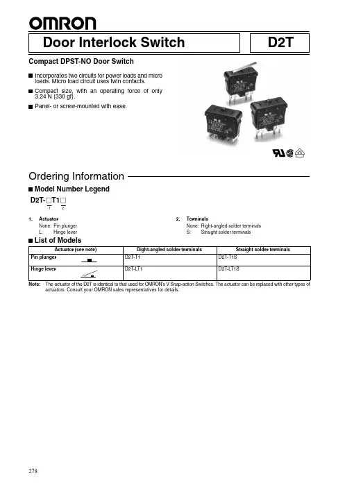
Door Interlock Switch D2T Compact DPST-NO Door SwitchIncorporates two circuits for power loads and microloads. Micro load circuit uses twin contacts.Compact size, with an operating force of only3.24 N {330 gf}.Panel- or screw-mounted with ease.RCWD2T-j T1j121.ActuatorNone:Pin plungerL:Hinge lever 2.TerminalsNone:Right-angled solder terminalsS:Straight solder terminalsNote:The actuator of the D2T is identical to that used for OMRON’s V Snap-action Switches. The actuator can be replaced with other types of actuators. Consult your OMRON sales representatives for details.278279RatingsRated voltageResistive loadBetween terminals 1 and 2250 VAC 5 A Between terminals 3 and 4125 VAC0.1 ANote:The ratings values apply under the following trest conditions:Ambient temperature: 20±2°C Ambient humidity: 65±5%Operating frequency: 30 operations/minVoltage Resistive loadgBetween terminals 1 and 2Between terminals 3 and 4250 VAC125 VAC 5 A 5 A ---0.1 A 30 VDC6 A0.1 ACharacteristicsOperating speed 10 to 500 mm/s (pin plunger models)Operating frequency Mechanical:120 operations/min max.Electrical:30 operations/min max.Insulation resistance100 M Ω min. (at 500 VDC)Contact resistance (initial value)Between terminals 1 and 2:50 m Ω max.Between terminals 3 and 4:100 m Ω max.Dielectric strength (see note 2)1,000 VAC for 1 min 50/60 Hz between terminals of same polarity1,500 VAC for 1 min 50/60 Hz between current-carrying metal part and ground (see note 1),between each terminal and non-current-carrying metal part, and between terminals of different polarityVibration resistance (see note 3)Malfunction: 10 to 55 Hz, 1.5-mm double amplitude Shock resistance (see note 3)Destruction: 1,000 m/s 2 {approx. 100G} max. Malfunction: 300 m/s 2 {approx. 30G} max.Durability (see note 4)Mechanical:100,000 operations min. (60 operations/min)Electrical:100,000 operations min. (30 operations/min)Degree of protection IEC IP40Degree of protection againstelectric shockClass I Proof tracking index (PTI)175Ambient operating temperature –25°C to 85°C (at ambient humidity of 60% max.) (with no icing)Ambient operating humidity 85% max. (for 5°C to 35°C)Weight Approx. 10 g (pin plunger models)Note:1.The data given above are initial values.2.The dielectric strength shown in the table indicates a value for models with a Separator.3.For the pin plunger models, the above values apply for use at both the free position and total travel position. For the lever models,they apply at the total travel position. Contact opening or closing time is within 1 ms.4.For testing conditions, consult your OMRON sales representative.280Consult your OMRON sales representative for specific models with standard approvals.UL1054 (File No. E41515)/CSA C22.2 No. 55 (File No. LR21642)Rated voltage Betweenterminals 1 and 2Betweenterminals 3 and 4125 VAC 5 A 0.1 A (for 100,000operations)250 VAC5 A---EN61058-1 (File No. 120144, VDE approval)Rated voltage Betweenterminals 1 and 2Betweenterminals 3 and 4125 VAC ---0.1 A 250 VAC5 A---Testing conditions: 5E4 (50,000 operations), T85 (0°C to 85°C)ItemBetween terminals 1and 2Between terminals 3and 4Contact SpecificationRivet PlatedMaterial Silver Gap(standard value)1 mm 1.4 mm Inrush current60 A max.---Minimum applicable load160 mA at 5 VDC1 mA at 5 VDC COM Terminal 1COM Terminal 3NO Terminal 4NOTerminal 2Micro load Power loadDPST-NONote:The circuit switching power loads has a snap-action mech-anism and the circuit switching micro loads has a slow-ac-tion mechanism.Solder terminal t=0.51.2-dia.holeSolder terminal t=0.51.2-dia. hole2.6-dia. hole2.6-dia. holeAngled TerminalsStraight Terminals2.8±0.17.1±0.112.8±0.17.1±0.1281Two, M3 screw holes26.4±0.1Panel Cutout Dimensions (Panel thickness: 1.5 to 2 mm)Four, 0.5R max.11.9+0.2–031.0+0.2–0Note:1.All units are in millimeters unless otherwise indicated.2.Unless otherwise specified, a tolerance of ±0.4 mm applies to all dimensions.3.The following illustrations and dimensions are for D2T models with angled terminals. Refer to the dimensions in Terminals for the straight terminals of the D2T.4.Model D2T-T1D2T-T1S OF max. 3.24 N {330 gf}RF min.{g }0.5 N {50 gf}TTF max.{g }6.37 N {650 gf}OT min.0.8 mm OP4.4±0.6 mm (see note)Model D2T-LT1D2T-LT1S OF max. 1.47 N {150 gf}RF min.{g }0.2 N {20 gf}TTF max.{g }2.45 N {250 gf}OT min. 1.6 mm OP6.9±1.3 mm (see note)MountingUse M3 mounting screws to mount the Switch. Tighten the screws to a torque of 0.4 to 0.6 N S m {4 to 6 kgf S cm}.Mounting HolesWhen mounting on a metal surface, be sure to provide a Separator between the Switch and mounting plate.ALL DIMENSIONS SHOWN ARE IN MILLIMETERS.To convert millimeters into inches, multiply by 0.03937. To convert grams into ounces, multiply by 0.03527.Cat. No. B097-E1-02BPin Plunger ModelsD2T-T1D2T-T1SSolder terminal2.6holeTwo, 2.5R1.2 hole3.1+0.13–0.03dia. holes 3.4±0.15 dia.26.4±0.15 2.8±0.115.35±0.2Note:Operating sequence of the circuit between terminals 1 and 2 and the circuit between terminals 3 and 4 is not specified.Hinge Lever ModelsD2T-LT1D2T-LT1St=0.5Solder terminalt = 0.5(Stainless-steel lever)30.9±0.8Note:Operating sequence of the circuit between terminals 1 and 2 and the circuit between terminals 3 and 4 is not specified.26•When switches are actually used, unforeseen accidents may occur. Before using a switch, perform all possible testing in advance.•Unless otherwise specified, ratings and performances given in this catalog are for standard test conditions (i.e., 15 to 35_C,25% to 75% humidity, and 86 to 106 kPa atmospheric pressure).When performing testing in the actual application, always use the same conditions as will be used in actual usage conditions for both the load and the operating environment.•Reference data provided in this catalog represents actual measurements from production samples in graph form. All reference data values are nominal.•All ratings and performance values provided in this catalog are the results of a single test each rating and performance value therefore may not be met for composite conditions.Select an appropriate switch for the operating environment and load conditions.•Use the Selection Guide to select a suitable switch for the rated current, operating load, actuator type, and operating environ-ment.•It is not recommended to use a switch for a large current to switch a micro current, in terms of contact reliability. Select a switch that is suitable for the current actually being switched.•Use a sealed switch in environments subject to water, other liquids and excessive dirt or dust.tive load in a DC circuit.Inrush Currenti (Inrush current)io (Steady-state current)I (A)tApplication of Switch to Electronic CircuitsThe Basic switch may have contact bouncing or chattering in switching, thus generating noise or pulse signals that may interfere the operation of electronic circuits or audio equipment. To prevent this, take the following countermeasures.•Design the circuits so that they include appropriate CR circuits to absorb noise or pulse signals.•Use switches with gold-plated contacts for micro loads, which are more resistive to environmental conditions.Switches for Micro LoadsIf a switch for a general load is used for switching a micro load, it may cause contact failures. Be sure to select a switch within the permis-sible range. Even if a switch for a micro load is used within the per-missible range, the inrush current of the load may deteriorate the contacts, thus decreasing the durability of the switch. Therefore, if necessary, insert a proper contact protective circuit.27Contact Protective CircuitApply a contact protective circuit (surge killer) to extend contact du-rability, prevent noise, and suppress the generation of carbide or ni-tric acid due to arc. Be sure to apply the contact protective circuit properly, otherwise an adverse effect may result. Some typical examples of contact protective circuit are described in the following table.When a switch is used under high humidity, arcs resulting from cer-tain types of load (e.g., inductive loads) will generate nitrious oxides and, with mater the nitrious oxides will become nitric acid, which will corrode internal metal parts and may cause malfunctions. Always use a contact protective circuit according to information provided in the following table when using a switch under circuit conditions of frequent switching and arcing.The use of a contact protective circuit may delay the response time of the load.Typical Examples of Contact Protective Circuits (Surge Killers)Power supplyInductive loadInductive loade r s u p p l yP o w e r s u p p l yInductive loadInductive loadInductive loadDo not apply contact protective circuit as shown below.LoadPower supplyLoadPower supply28Operating Stroke SettingThe setting of stroke is very important for a switch to operate with high reliability.The chart below shows the relationship among operating force,stroke, and contact force. To obtain high reliability from a switch, a switch actuator must be manipulated within an appropriate range of operating force.Be sure to pay the utmost attention when mounting a switch.O p e r a t i n g f o r c eC o n t a c t f o r c eRelease StrokeStrokeRelease FP TTPMake sure that the operating body is set so that the actuator should return to the free position when the operating body has moved if a switch is used to form a normally closed (NC) circuit. If a switch is used to form a normally open (NO) circuit, the operating body must move the switch actuator to the distance of 70% to 100% of the rated overtravel (OT) of the switch.Operating bodyPT (Pretravel)Install a stopper.FP (Free position)OP (Operating position)OT (Overtravel)TTP(Total travel position)If stroke is set in the vicinity of the operating position (OP) or the re-leasing position (RP), contact force may become unstable. As a re-sult, the switch cannot ensure high reliability. F urthermore, the switch may malfunction due to vibration or shock.If stroke is set exceeding the total travel position (TTP), the moment of inertia of the operating body may damage the actuator or the switch itself, and the stress applied to the moving spring inside the switch will increase and then, the durability of the switch may be de-teriorated.IncorrectCorrectSwitching Speed and FrequencyThe switching frequency and speed of a switch have a great influ-ence on the performance of the switch. Pay attention to the follow-ing.•If the actuator is operated too slowly, the switching operation may become unstable, causing contact failures or contact welding.•If the actuator is operated too quickly, the switch may be damaged by shock.•If the switching frequency is too high, the switching of the contacts cannot catch up with the operating speed of the actuator.•If the operating frequency is extremely low (i.e., once a month or less frequent), a film may be generated on the surface of the contacts, which may cause contact failures.The permissible switching speed and switching frequency of a switch indicate the operational reliability of the switch. The durability of a switch is based on operation under specific conditions regard-ing the switching speed and switching frequency. The durability of a switch may not meet the durability due to conditions even if the switch is operated within the permissible switching speed and fre-quency ranges. T est a switch sample under the actual conditions to ascertain its durability.Operating ConditionDo not leave a switch with the actuator depressed for a long time,otherwise the parts of the switch may soon deteriorate and the changes of its characteristics operating may result.Operating MethodThe operating method has a great influence on the performance of a switch. Consider the following before operating a switch.•Design the operating body (i.e., cam or dog) so that it will operate the actuator smoothly. If the actuator snaps backwards quickly orreceives shock due to the shape of the operating body, its durability may be deteriorated.Snap-back Shock operationIncorrectCorrect29Snap-back IncorrectCorrectShock operation•Make sure that no improper force is applied to the actuator,otherwise the actuator may incur local abrasion. As a result, the actuator may become damaged or its durability may be deteriorated.DogRollerIncorrectCorrectOperatingbodyOperatingbody: Correct : Incorrect•Make sure that the operating body moves in a direction where the actuator moves. If the actuator is a pin plunger type, make sure that the operating body presses the pin plunger vertically.•Operate the actuator of a hinge roller lever or simulated hingelever type in the direction shown below.IncorrectCorrect•Set the angle of the cam or dog (θ) for roller levers and similar actuators to the range between 30_ and 45_. If the angle is too large, an abnormally large horizontal stress will be applied to the lever.•Do not modify the actuator. If the actuator is modified, excessive external force may be applied to the internal switch mechanism,characteristics may change, and the switch may stop functioning.•If an external actuator is used as an operating object, check the material and thickness of the lever to make sure that the force applied to the lever is within the permissible range.SecuringWhen mounting a switch, be sure to use the specified mounting screws and tighten the screws with flat washers or spring washers securely.However, the switch housing may incur crack damage if it comes into contact with the spring washers directly. In that case make sure that the flat washers come into contact with the switch housing as shown below. Do not subject the switch to excessive shock or high-frequency vibrations when mounting (e.g., do not use an impact driver) as it may cause contacts stick or switch damage.ScrewFlat washer Spring washer ResinIncorrectCorrectDo not modify the switch in any way, for example, by widening the mounting holes.Locking AgentIf glue or locking agent is applied, make sure that it does not stick to the moving parts or intrude into the inside of the switch, otherwise the switch may have operating failure or contact failure. Some types of glue or locking agent may generate gas that has a bad influence on the switch. Pay the utmost attention when selecting glue or lock-ing agent.WiringMake sure that the lead wires are connected with no inappropriate pulling force.Mounting LocationBe sure not to mount a switch in locations where the switch may be actuated by mistake.Maintenance and InspectionMake sure that a switch is mounted in locations that allow easy inspection or replacement of the switch.Mounting DirectionWhen using a switch with a low operating force mounted with a long lever, make sure that the switch is mounted in the direction where the weight of the lever is not applied to the pushbutton directly,otherwise the switch may have releasing failures.Terminal ConnectionsSolder TerminalsWhen soldering lead wires to a switch, make sure that the tempera-ture of the iron tip is 380°C maximum. Improper soldering may cause abnormal heat radiation from the switch and the switch may burn.Complete soldering within 5 seconds at 350°C or within 3 seconds at 380°C. If heat is applied for longer period of time, switch charac-teristics will be deteriorated, e.g., the case will melt and lead wire insulation will scorch.Soldering conditions are even more strict for ultra subminiature switches. Refer to the Precautions for individual models for details.Quick-Connect TerminalsUse the specified receptacles to connect to quick-connect termi-nals. Do not apply excessive force horizontally or vertically to the30terminals, otherwise the terminal may be deformed or the housing may be damaged.Wiring WorkWhen wiring a switch, check the insulation distance between the switch and the mounting plate. If the insulation distance is insuffi-cient, use an insulation guard or separator. Be particularly careful when mounting a switch to metal.Use wire sizes suitable for the applied voltage and carrying current.Do not wire a switch while power is being supplied.Using SeparatorsIf providing sufficient insulation distance is a problem or there are metal components or copper wire near a switch, use a switch withan insulation guard or use a separator (order separately) to providesufficient insulation distance.Separator for SS jSeparator for V jSeparator SeparatorSeparator for Z jSeparatorSoldering PrecautionsWhen soldering by hand, place the terminal horizontal to the ground, use a soldering iron with a suitable heat capacity and a suit-able amount of solder, and complete soldering quickly. Prevent flux from entering a switch by exhausting flux gas with an exhaust fan and by avoiding the contact of the tip of the soldering iron and the switch body. Flux gas inside a switch may cause contact failure. Do not apply any force to the terminal or wire immediately after solder-ing.Tip of soldering ironIncorrect CorrectWhen soldering automatically, adjust the amount of solder so that flux does not float onto the top of PCB. If flux enters the switch, it can cause contact failure.HandlingDo not apply oil, grease, or other lubricants to the sliding parts of a switch. The intrusion of oil, grease, or other lubricants into the inter-nal part may cause operating failure or contact failure.Operating EnvironmentA general switch is not water-resistant. Protect the switch appropri-ately when using the switch in places with water or oil spray.Do not use a switch under the condition where vibration or shock is continuously applied to the switch. If continuous vibration or shock is applied to a switch, contact failure, malfunction, or decrease in du-rability may be caused by abrasive powder generated from the inter-nal parts. If excessive vibration or shock is applied to a switch, the contacts may malfunction, stick, or be damaged.Mount a switch in the location where vibration and shock is not ap-plied to the switch and in the direction where they do not resonate.Do not use a switch in the atmosphere of corrosive gas, such as sulfuric gas (H 2S or SO 2), ammonium gas (NH 3), nitric gas (HNO 3),or chlorine gas (Cl 2), or in the atmosphere of high temperature and humidity. Otherwise, contact failure or corrosion damage may re-sult.If a switch is used in the atmosphere of silicon gas, arc energy may attract silicon dioxide (SiO 2) to the contacts and contact failure may result. If there is silicon oil, silicon sealant, a wire covered with sili-con, or any other silicon-based product near the switch, attach a contact protective circuit to suppress the arcing of the switch or elim-inate the source of silicon gas generation. Even for a sealed switch,it may not be possible to prevent all of the gas from penetrating the seal rubber, and contact failure may result.Be sure to use a switch at a temperature and humidity within the specified ranges. If a switch is exposed to radical temperature chan-ges or intense heat, the characteristics of the switch may change.Separate the switch as far as possible from sources of heat to elimi-nate the influence.Storage EnvironmentWhen storing a switch, consider countermeasures (e.g., storing in a plastic bag) to prevent discoloration resulting from sulfidization of terminals (silver-plated). Make sure that the location is free of corro-sive gas or dust with no high temperature or humidity. It is recom-mended that a switch be inspected before use if it is stored for three months or more after the production, depending on the location.31Type Location of failure Failure Possible causeCorrective actionFailures l t d t ContactContact f il Dust and dirt on the contacts.Remove the cause of the problem, place th it h i b l d related to electricalfailureWater or other liquid has penetrated into aswitch.p ,p the switch in a box, or use a sealed switch.characteristicsChemical substances have been generated on the contact surface due to theatmosphere containing chemical corrosive gas.Use a switch having contacts with high environmental resistivity (such as gold or alloy contacts).Chemical substances have been generated on the contact surface when the switch switches a very low load.Solder flux has penetrated into the switch.Review the soldering method or use a sealed or flux-tight switch.Silicon gas exists near the switch.Remove the material generating gas, or adjust contact capacity to prevent formation of silicon compounds on the contacts.Malfunction The contacts are separated from each otherby vibration or shock.Use a switch having a high contact force (generally a high OF).Contact welding The load connected to the switch is too high.Switch the load with a high-capacity relay or magnetic relay or insert a contact protection circuit.Insulation degradation (b i )Contacts have been melted and scattered by arc.Switch the load with a high-capacity relay or magnetic relay.deg ada o (burning)Water has penetrated into the switch because the switch has been used in an extremely hot environment.Remove the cause of the problem, place the switch in a box, or use a sealed switch.Liquid has penetrated into the switch and been carbonized by arc heat.Failures related to mechanical h t i tiActuatorOperatingfailureThe sliding part of the actuator has been damaged because an excessive force was applied on the actuator.Make sure that no excessive force isapplied to the actuator, or use an auxiliary actuator mechanically strong.characteristics Foreign material like dust, dirt and oil has penetrated into the switch.Remove the cause of the problem or place the switch in a box.The actuator does not release because the operating body is too heavy.Use a switch having a higher OF.The switch is loosely installed and thus does not operate even when the actuator is at the rated OP .Secure the switch.Low d bilit The shape of the dog or cam is improper.Change the design of the dog or cam.durability The operating method is improper.The operating speed is too high.Review the operating stroke and operating speed.DamageA shock has been applied to the actuator.Remove the cause of problem or use a switch mechanically strong.The caulked part is not good enough or the assembled condition is poor.Replace the switch with a new one.Deformation or drop-outActuator was subjected to an excessive force and force from an inappropriate direction.Review the handling and operating method.Mounting section Damage Screws have not been inserted straight.Check and correct screw insertion method.sec oThe mounting screws were tightened withtoo much torque.Tighten the screws with an appropriate torque.The mounting pitch is wrong.Correct the pitch.The switch is not installed on a flat surface.Install the switch on a flat surface.Terminal DamageAn excessive force was applied to the terminal while being wired.Do not apply an excessive force.The plastic part has been deformed by soldering heat.Reduce the soldering time or soldering temperature. (Refer to the information given under Precautions for that model.)。