STV3中文说明书V3.03
- 格式:pdf
- 大小:426.98 KB
- 文档页数:2
法律声明版权所有深圳市易检车服科技有限公司。
保留一切权利。
非经本公司书面许可,任何单位和个人不得擅自抄袭、复制本文档内容的部分或全部,并不得以任何形式传播。
注意本文档中描述的全部或部分产品、服务或特性可能不在您的购买或使用范围之内。
除非合同另有约定,易检车服公司对本文档内容不做任何明示或默认的声明或保证。
手册升级,恕不另行通知,若需最新手册,请通过以下方式获取:与您的产品销售商联系;登陆易检车服官方网站下载。
重要提示本手册介绍了如何正确使用本产品。
操作手册所述流程前,请务必认真阅读安全注意事项后再使用该产品。
安全信息文中使用的指示图标说明如下:说明说明突出重要信息和使用窍门,对您的操作进行必要的提示、补充和说明。
注意提醒您在操作中必须注意和遵循某些事项。
如未按照要求操作,可能会出现设备损坏、数据丢失等不可预知的结果。
警告警告您可能会存在潜在的危险,若无法避免,可能会造成较为严重的人身伤害。
更多服务服务热线:400-930-1883注意事项• 请勿在多灰、潮湿、肮脏或靠近磁场的地方使用设备,以免引起设备内部电路故障。
• 请勿在雷雨天气使用本设备。
雷雨天气可能导致设备故障或电击危险。
• 请在温度0℃到50℃范围内存放设备及其配件。
当环境温度过高或过低时,可能会引起设备故障。
• 请勿将设备放置在阳光直射的地方,如汽车仪表盘或窗台处。
• 请避免设备及其配件雨淋或受潮,否则可能导致火灾或触电危险。
• 请勿将设备靠近热源或裸露的火源,如电暖器、微波炉、烤箱、热水器、炉火、蜡烛或其他可能产生高温的地方。
包装清单以下附件仅供参考,详细包装清单,请参考随机附带的装箱清单或咨询当地经销商。
• 主机• 开关电源• 测试主线•••••• XTA001芯片转接座• 奔驰红外模拟采集钥匙•• 产品手册MCU转接板V1MCU转接板V2四代仪表免拆EEPROM全丢线BENCH模式线MCU飞线EEPROM转接板目录1 关于本手册 (1)1.1 目标读者 (1)1.2 约定 (1)1.3 图标定义 (1)2 关于ST G3 (2)2.1 产品介绍 (2)2.2 技术参数 (3)2.3 电源 (4)2.4 配件列表 (4)3 诊断 (6)3.1 常用操作 (6)3.1.1 建立硬件连接 (6)3.1.2 建立无线连接 (7)3.1.3 执行常规操作 (7)3.2 诊断操作 (8)3.2.1 钥匙编程 (8)3.2.2 变速箱编程 (13)3.2.3 发动机编程 (16)4 软件升级 (24)保修信息 (25)服务信息 (25)1 关于本手册本手册包含了产品操作使用说明。

Universal Module V3 User guideContentsProduct information page 3 T echnical specifications page 4 Wiring diagram page 5 Wiring diagramDoor strike / Magnetic door lock page 6 Installation page 7 Setup page 8-9 Remote access/Integration page 10 Support page 11Product information 3/12 The Danalock Universal module is a device for controlling all 12-24V powered commercially available locking mechanisms; door strikes, electromechanical or magnetic locks, gates etc.The module works in parallel with what is already installed or in any new installation.The module has two relay outputs and one power output. The relays or the power-output can be controlled remotely with the Danalock app via Android (from version 4.4.4) and iOS (from iOS 9.0 and iPhone 4S) smartphones. The relay is both Bluetooth Low Energy 4.0 and/or Z-Wave driven.Relay modeThe two relays can be operated either parallel or separately. The relays are working for a desired time (1-180 sec.) or permanent when activated. The activation for the relays can be delayed for relay 2 after activating relay 1. The two relays can be setup individually for permanent activation or for a desired time.T echnical specifications 4/12 Operating voltage range 12-24V DC, 12-24V ACMax input (at 24V) 100mA Number of relays 2 Type of relays Potential-freecontacts (NO/NC) Max AC power 1A at 12V Max AC current 1A at 12V Max relay voltage 48 VWireless communication Bluetooth 4.0LE/Z-Wave Plus (optional) Bluetooth range 5-10 metersWiring diagram 5/12ellowWiring diagram - Magnetic door lock 6/12BlackGrey Power input 12-24V AC/DC 1 ampGrey 12/24 in White 12/24 inBrown GroundWhite Ground input 12-24V AC/DC 1 amp Red Yellow Green Relay 2: Normally openViolet Relay 2: Normally closedBlue Relay 2: CommenWiring diagram - Door strike7/12Grey 12/24 in White 12/24 inInstallation 8/12 1. Mounting instructionConnect the Universal Module to the relevant motor drive while considering the wiring diagram.Note!Please make sure to connect the Universal Module to a smartphone during installation. As soon as you are registered as owner, no one else is able to control the door/gate, and it is only you who can grant other users access.2. Connect to the smartphoneT o connect the Module to a smartphone, please follow the Danalock App User Guide on:https:///?page_id=2894When installing the Module you will be asked to set the Relay time. In the User guide for the motorized door lock you will find the recommended time (pulse = 1sec). Per default, the Universal Module will switch off after 1 sec.Note!The Relay time can be changed under settings at any time.User Guide 9/12Y ou find the updated version of the Danalock App User Guide under:https:///?page_id=2894Among other things, the guide will show you how to share access. If you like to change owner/administrator of the Module, you have to delete the Module from the app before connecting it to a new owner.Note!Please only delete the Module from the keychain when in Bluetooth range of the Module. If you are not in Bluetooth range, you will have to reset (see “T ouch button commands) it by pressing the button on the Module. If the Module is a built-in solution, a reset can cause additional charges from eg. a locksmith.T ouch button commands 10/12 Y ou find the gold-colored touch button in one corner of the circuit board. One short press switches the Relay off. Holding down/pressing the touch button will trigger the following commands:1 flash switches the relays off.2 flashes puts the Module inZ-Wave inclusion mode.5 flashes resets the key.10 flashes means a factory resetof all key and relay settings.Remote access/Integration 11/12DanabridgeThe Universal Module is only accessible when the user is in Bluetooth range. T o gain remote access, you can use a spare smartphone or tablet: https:///?page_id=2981Z-WaveThe Danalock Universal Module with Z-Wave is compatible with a long list of gateways.Read more about it here:https:///?page_id=2597Support 12/12You will find a list with frequently asked questions here: https:///?page_id=3417Please write or call us in case of any questions:+0045 42428122Poly-control ApSGammel Stillingvej 427 C, 8462 Harlev - DK*************************************+45 4242 8122。


SEnsorV3Sehr geehrter Kunde,wir freuen uns, dass Sie sich für die PowerBox Sensor V3 aus unserem Sortiment entschieden haben. Wir wünschen Ihnen mit der PowerBox Sensor V3 viel Freude und Erfolg!PRODUKTBESCHREIBUNGDie PowerBox Sensor V3 ist dritte Generation der weltweit bekannten PowerBox Sensor. Die PowerBox Sensor ist aufgrund ihrer kompakten Bauform und der viel-seitigen Einsatzmöglichkeiten schon seit fast 20 Jahren der Standard in kleinen bis mittelgroßen Modellen.Die Sensor V3 konnte dank dem Einsatz modernster Bauelemente deutlich verklei-nert werden. So wurde die Tiefe von 22 mm auf 11 mm genau halbiert. Trotzdem passt die Sensor V3 exakt in den Ausschnitt seines Vorgängers!Durch den Einsatz eines edlen, gefrästen und eloxierten Aluminiumgehäuses wurde die nutzbare Kühlleistung deutlich erhöht – die PowerBox Sensor V3 kann ca. 35 % mehr Dauerstrom leisten! Die kurzzeitige Belastbarkeit hat sich sogar verdoppelt – über mehrere Sekunden verkraftet die Sensor V3 über 20 A!Die Sensor V3 hat zwei wählbare Ausgangsspannungen – für normale Servos kann auf 6.0 V geregelt werden, für HV Servos stehen geregelte 7,8 V zur Verfü-gung, sofern der Akku eine höhere Eingangsspannung liefert!Als Stromversorgung kann zwischen vier verschiedenen Akkutypen gewählt wer-den: LiPo, LiIon, LiFePo und NiMh. Zur Spannungsanzeige der Akkus kommen ul-trahelle RGB LED´s zum Einsatz die mit verschiedenen Farben den Ladestatus der Akkus signalisieren.Für CORE Kunden gibt es noch ein besonderes Feature oben drauf: beide Akku-spannungen können per Telemetrie direkt auf dem Sender angezeigt werden!FEATURES+ Leistungsstarke Akkuweiche+ Sehr leichte und kompakte Bauform+ Doppelt geregelte Ausgangsspannung+ Redundante Schalter- und Reglerauslegung+ Einstellbare Ausgangsspannung 6,0 V oder 7,8 V+ Spannungsanzeige für jeden Akku separat über RGB LED´s+ Telemetrie-Unterstützung für die CORE+ 4 Akkutypen werden unterstützt: 2s LiPo, 2s LiIon, 2s LiFePo and 5s NiMH+ Reglerüberwachung+ Unterdrückung von Servo-Rückströmen1. AUFBAU UND ANSCHLÜSSE2. EINBAU UND ANSCHLIESSEN DER AKKUSDie PowerBox Sensor V3 wird an einer schwingungsarmen Stelle im Modell ein-gebaut. Reine GfK-Seitenwände eines Motormodells sollten mit einem 3 – 4 mm starken Sperrholzbrett, das von innen eingeklebt wird, gestützt werden, um Vibrati-onen zu minimieren und den Schrauben sicheren Halt zu geben.Stecken Sie zwei Akkus Ihrer Wahl – richtig gepolt – an die Akkueingänge an. Es können je 2x 2s LiPo/LiIon, 2s LiFePo oder 5s NiMH Akkus verwendet werden. Wir empfehlen Ihnen den Einsatz der PowerPak 2.5x2 Pro Akkus, die dank der integ-rierten Ladetechnik besonders sicher und einfach in der Handhabung sind.Akkuanschlüsse RGB LED´s zur Spannungs- und ZustandsanzeigeAusgänge zum EmpfängerHinweis bei selbst konfigurierten Akkupacks: Wird der Akku falsch gepolt an-gesteckt, sind die eingebauten Linear- Regler sofort zerstört!Die Ausgänge der Weiche können je nach Empfängertyp unterschiedlich ange-schlossen werden. Die Ausgänge der Sensor V3 sind einmal 2-adrig und einmal 3-adrig. Bei allen Systemen außer CORE sind die beiden Ausgänge als identisch zu betrachten.Bei Empfängern, die nur einen Akkueingang haben, wird ein Ausgang der Sensor V3 an den Akkueingang des Empfängers angeschlossen, der andere an einen frei-en Servoausgang. Sollte kein Servoausgang mehr frei sein, kann ein V-Kabel an einen Servoausgang angesteckt werden, um die Sensor V3 und das Servo anzu-schließen.Bei CORE Empfängern sollten Sie beachten, dass die 3-adrige Leitung am P²BUS- Eingang des Empfängers angeschlossen werden muss, um die Telemetriedaten der Akkus auf den Sender zu bekommen.Wichtig: Die 2-adrige Leitung wird an einen freien Servoausgang angeschlos-sen – nicht am Fasttrack Ausgang! Die Versorgungsleitung von den P²BUS und Fasttrack Steckern zu den vorne angeschlossenen Servos reicht möglicherwei-se nicht aus, um alle angeschlossenen Servos zu versorgen!3. EIN- UND AUSSCHALTVORGANGDie Sensor V3 hat im Gegensatz zum Vorgängermodell nur noch eine Taste – das vereinfacht den Ein- und Ausschaltvorgang. Wie auch bei anderen PowerBox Gerä-ten mit einer Taste ist der Ein- und Ausschaltvorgang wie folgt:Drücken Sie die Taste ein bis zwei Sekunden, bis die LED´s violett leuchten, lassen Sie die Taste kurz los und bestätigen Sie mit einem zweiten, kurzen Tastendruck den Schaltvorgang.Einmal eingeschaltet kann die Weiche nur wieder mit den Tasten ausgeschaltet werden. Wackelkontakte oder Unterbrechungen während des Betriebes führen nicht zu einem Ausschalten der PowerBox. Der letzte Schaltzustand wird immer abgespeichert.4. EINSTELLEN DER AKKUANZEIGEDamit die LED Akkuanzeige richtig funktioniert, müssen Sie den Akkutyp einstellen. Dazu schalten Sie zuerst die PowerBox ein. Jetzt drücken Sie erneut die Taste und halten diese gedrückt.Nach ca. 5 Sekunden schalten sich die LED´s aus und eine Sequenz mit verschie-denen Farben beginnt. Jede Farbe ist einem Akkutyp zugeordnet. Lassen Sie die Taste los, wenn die Farbe angezeigt wird, die Ihrem Akkutyp entspricht. Der Akku-typ wird damit abgespeichert.0 – 20 %Information zur LED Anzeige: Die Anzeige ist nicht linear zur Akkuspannung. Es wurden verschiedene gängige Akkutypen vermessen, die im Mittel eine Entlade-kurve ergeben. Diese Entladekurve wird verwendet, um eine prozentuale Anzeige zu ermöglichen.Die LED Anzeige hat folgende Bedeutung für den Akkuinhalt:5. EINSTELLEN DER AUSGANGSSPANNUNGDie PowerBox Sensor V3 kann auf zwei verschiedene Ausgangsspannungen ein-gestellt werden. Zum einen auf 6,0 V für reguläre Servos und zum anderen auf 7,8 V für HV Servos. Achten Sie bei dieser Einstellung darauf, dass alle angeschlossenen Komponenten hochvolt-tauglich sind.Der Vorteil daran, die Spannung auf 7,8 V zu regeln, statt die Akkuspannung einfach durchzulassen, besteht darin, dass die anfänglich nach dem Laden vorhandene hohe Akkuspannung ausgeregelt wird. Somit erhält man von Anfang an eine kons-tante Spannung und damit eine länger gleichbleibende Servogeschwindigkeit- und Kraft.Zum Umstellen der Ausgangsspannung drücken Sie die Taste und stecken bei gedrückter Taste einen der Akkus ein. Die LED wird zuerst grün leuchten, nach 3 Sekunden rot. Je nachdem, bei welcher Farbe Sie loslassen, stellt sich die Aus-gangsspannung um. Dabei bedeutet grün = 6,0 V und rot = 7,8 V.Abschließend blinkt die LED weiß, um den Einstellvorgang zu bestätigen.Verfahren Sie genauso mit dem zweiten Akkuanschluss.Hinweise zur Reglerleistung:Der maximale Strom, den die PowerBox Sensor V3 abgeben kann, ist von äußeren Faktoren wie Akkutyp, eingestellter Ausgangsspannung, und auch stark von der Kühlung abhängig. Im Idealfall ist die Weiche außen am Modell angebracht oder innen so verbaut, dass zumindest ein leichter Fahrtwind für Kühlung sorgt. Beson-ders wenn die Sensor V3 mit LiPo/LiIon Zellen mit 6,0 V Ausgangsspannung betrie-ben wird, sollte die Anzahl der angeschlossenen Servos im empfohlenen Rahmen bleiben. Wobei auch hier gilt, dass z.B. 8 kleine Flächenservos weniger Leistung brauchen als 5x 30 kg Servos.In der 7,8 V Einstellung muss die Weiche kaum regeln und Energie vernichten, da-mit steigt die Ausgangsleistung der PowerBox Sensor V3 deutlich an! Das gleiche gilt für die 6,0 V Einstellung, wenn LiFePo oder NiMh Akkus verwendet werden, die bereits mit niedriger Eingangsspannung an dem Eingang der Sensor V3 ange-schlossen werden.Sollten Sie sich nicht sicher sein, ob die PowerBox Sensor V3 Ihren Stromanfor-derungen gewachsen ist, bewegen Sie alle Servos am Boden für ca. 30 Sekunden. Sollte sich die Sensor V3 stark erhitzen (über 60 °C), sollten Servos, Gestänge und Anlenkungen überprüft werden. Ist hier alles in Ordnung, sollte die für größere Leis-tungen konzipierte PowerBox Source verwendet werden.6. REGLERFEHLERDie Spannungsregler werden ständig auf Funktion überwacht. Sollte sich die Aus-gangsspannung außerhalb der Sollspannung befinden, wird das durch schnelles violettes Blinken der LED´s angezeigt. Reglerfehler treten z.B. nach verpoltem Ein-stecken der Akku auf.In dem Fall wenden Sie sich bitte an den Service!7. TECHNISCHE DATENBetriebsspannung: 4,0 V – 9,0 VStromversorgung: 2s LiPo, 2s LiIon, 2s LiFePo, 5s NiMh Stromaufnahme Betrieb: 30 mAStromaufnahme Standby: 10 μAStrombelastbarkeit Spitze: 2 x 10 ADropout Spannung: 0,25 VAusgangsspannung: 6,0 V/ 7,8 V stabilisiertUnterstützes Telemetriesystem: P²BUSAbmessungen: 65 x 26 x 11 mmGewicht: 30 gTemperaturbereich: -30 °C bis +105 °C8. ABMESSUNGEN9. LIEFERUMFANG- PowerBox Sensor V3- 2x Befestigungsschrauben- Bedienungsanleitung in Deutsch und Englisch10. SERVICEHINWEISUm unseren Kunden guten Service bieten zu können, wurde ein Support Forum für alle Fragen, die unsere Produkte betreffen, eingerichtet. Das entlastet uns stark, um nicht immer wieder häufig auftretende Fragen erneut beantworten zu müssen, und gibt Ihnen die Möglichkeit, schnelle Hilfe rund um die Uhr und auch an Wochenen-den zu erhalten. Die Antworten sind vom PowerBox Team, das garantiert auch die Richtigkeit der Antworten.Nutzen Sie bitte das Support Forum bevor Sie uns telefonisch kontaktieren.Sie finden das Forum unter folgender Adresse:11. GARANTIEBESTIMMUNGENPowerBox-Systems legt bei der Entwicklung und der Fertigung besonderen Wert auf höchsten Qualitätsstandard, garantiert …Made in Germany“!Wir gewähren deshalb auf die PowerBox Sensor V3 eine Garantie von 24 Mo-naten ab dem Verkaufsdatum. Die Garantie besteht darin, dass nachgewiesene Materialfehler von uns kostenlos behoben werden. Wir weisen vorsorglich darauf hin, dass wir uns vorbehalten, das Gerät auszutauschen, wenn eine Reparatur aus wirtschaftlichen Gründen nicht möglich ist.Eventuelle Reparaturen, die wir für Sie in unserem Service durchgeführt haben, ver-längern den Gewährleistungszeitraum nicht.Falsche Anwendung, z.B. durch Verpolung, sehr starke Vibrationen, zu hohe Span-nung, Nässe, Kraftstoff, Kurzschluss, schließt Garantieansprüche aus. Für Mängel, die auf besonders starke Abnutzung beruhen, gilt dies ebenfalls.Für Transportschäden und Verlust Ihrer Sen-dung können wir keine Haftung übernehmen.Im Gewährleistungsfall senden Sie uns dasGerät zusammen mit dem Kaufbeleg und einerFehlerbeschreibung an die folgende Adresse:SERVICE ADRESSE PowerBox-Systems GmbH Ludwig-Auer-Straße 5D-86609 Donauwörth Germany12. HAFTUNGSAUSSCHLUSSSowohl die Einhaltung der Montagehinweise als auch die Bedingungen beim Be-trieb der PowerBox Sensor V3, sowie die Wartung der gesamten Fernsteuerungs-anlage, können von uns nicht überwacht werden.Daher übernehmen wir keinerlei Haftung für Verluste, Schäden oder Kosten, die sich aus der Anwendung und aus dem Betrieb der PowerBox Sensor V3 ergeben oder in irgendeiner Weise damit zusammen hängen können. Soweit es gesetzlich zulässig ist, wird die Pflicht zur Schadensersatzleistung, gleich aus welchen recht-lichen Gründen, auf den Rechnungsbetrag der Produkte aus unserem Haus, die an dem Ereignis beteiligt sind, begrenzt.Wir wünschen Ihnen Erfolg beim Einsatz mit Ihrer neuen PowerBox Sensor V3! Donauwörth, Dezember 2020。

SEnsorV3Dear customer,congratulations on your decision to purchase the PowerBox Sensor V3 from our range. We wish you many hours of pleasure and success with the PowerBox Sensor V3!PRODUCT DESCRIPTIONThe PowerBox Sensor V3 is the third generation of the PowerBox Sensor, which is well-known throughout the world. For almost twenty years the PowerBox Sensor has represented the standard for small to medium-sized models thanks to its compact format and versatility.By using the latest components we have been able to reduce the size of the Sensor V3 significantly. For example, the case is now exactly half as deep (11 mm compa-red with 22 mm). Nevertheless, the Sensor V3 still fits neatly in the aperture used by its predecessor.The introduction of a top-quality aluminium case, machined and anodised, has brought a substantial increase in the unit’s cooling efficiency, with the result that the maximum continuous current capacity of the PowerBox Sensor V3 is around 35 % higher. In fact, the peak load capacity is twice as high: the Sensor V3 can handle more than 20 A for several seconds!The Sensor V3 offers two user-selectable output voltages: for normal servos it can be set to a regulated 6.0 V, while a regulated 7.8 V is available for HV servos– pro-vided that the batteries supply the higher input voltage required.Power to the unit can be drawn from four different battery types: LiPo, LiIon, LiFePo, NiMH. Ultra-bright RGB LEDs are fitted to indicate battery voltage; they light up in various colours to display the charge status of the batteries.CORE users also benefit from one special additional feature: both battery voltages can be displayed directly on the transmitter by means of telemetry.FEATURES+ High-performance battery backer+ Ultra-light unit, compact format+ Double regulated output voltage+ Redundant switch and regulator circuitry+ User-selectable output voltage: 6.0 V or 7.8 V+ Separate RGB LED voltage indicators for each battery+ Telemetry support for CORE systems+ Supports 4 different battery types: 2s LiPo, 2s LiIon, 2s LiFePo and 5s NiMH+ Regulator monitoring+ Suppression of servo feedback currents1. FEATURES AND CONNECTIONS2. INSTALLING AND CONNECTING THE BATTERIESThe PowerBox Sensor V3 should be installed in the model in a position where vibration levels are low. Solid GRP fuselage sides in a power model should be fitted with an internal 3 – 4 mm thick plywood plate to minimise vibration, and to provide ‘meat’ for the retaining screws.Connect the two batteries of your choice – with correct polarity – to the battery inputs. You can use either two 2s LiPo or LiIon, two 2s LiFePo or two 5s NiMH batteries. We recommend the use of PowerPak 2.5x2 Pro batteries, which are par-ticularly safe and simple to handle thanks to their integral charge circuitry.Push-button Battery sockets (MPX or JR)RGB LED voltage and status indicatorsReceiver outputsNote regarding home-assembled battery packs: connecting a battery to the unit with reversed polarity will immediately destroy the internal linear regulators!The backer’s outputs can be connected differently depending on the type of recei-ver used. The outputs of the Sensor V3 are present as two-core and three-core leads. For all systems except the CORE the two outputs can be considered to be identical.If your receiver only has one battery input, simply connect one of the Sensor V3’s outputs to the receiver’s battery input, and the other to any vacant servo output socket. If there is no servo output available, a Y-lead can be connected to a servo output socket, to which the Sensor V3 and the servo are connected.If you are using CORE receivers please note that the three-core lead must be connected to the receiver’s P²BUS input, otherwise the battery telemetry data will not be sent to the transmitter.Important: always connect the two-core lead to a vacant servo output - not the Fasttrack output! The power supply lead from the P²BUS and Fasttrack connec-tors to the connected servos may not be sufficient for all the servos connected to the system!3. SWITCHING ON AND OFFIn contrast to its predecessor, the Sensor V3 only has one button, and this simpli-fies the procedure for switching on and off. As with other PowerBox devices with a single button, the sequence is as follows:Hold the button pressed in for one or two seconds until the LEDs light up violet. Now release the button for a moment before pressing it again briefly; this confirms the switching process.Once switched on, the battery backer can only be switched off again using the button. Intermittent contacts or breaks while in use will not cause the PowerBox to switch off. The last switched status is always stored.4. SETTING THE BATTERY DISPLAYIt is essential to set the correct battery type to ensure that the LED battery indi-cators work correctly. The first step is to switch the PowerBox on, then hold the button pressed in again.After about five seconds the LEDs will go out, and a sequence of different colours begins. Each colour corresponds to a particular battery type. Simply release the button when the colour matching your battery type is displayed. The battery type is now stored.0 – 20 %Note regarding the LED display: the battery indicators do not follow battery voltage in a linear fashion. We have tested and measured various currently available bat-tery types, and produced an average discharge curve from this information; this discharge curve is used as the basis for a percentage indication of battery state.The LED indicators correspond to the battery status as follows:5. SETTING THE OUTPUT VOLTAGEThe PowerBox Sensor V3 can be set to either of two output voltages: 6.0 V for conventional servos, and 7.8 V for HV servos. If you opt for the higher setting, please ensure that all the components connected to the system are approved for high-voltage use.The advantage of regulating the voltage at 7.8 V, instead of simply allowing the full battery voltage to pass through, is that it suppresses the high battery voltage present just after charging. The voltage remains stable right from the outset, which means that servo speed and power are constant for a longer period.If you wish to change the output voltage, hold the button pressed in while you connect one of the batteries. The LED will initially light up green, then switch to red after three seconds. Release the button when the colour is correct for your required output voltage: green = 6.0 V, red = 7.8 V.The LED now flashes white to confirm that the set-up process is complete.Repeat the exact procedure with the second battery connection.Notes on regulator performance:The maximum current which the PowerBox Sensor V3 can supply varies accor-ding to external factors such as battery type and the selected output voltage, and it is also significantly affected by cooling efficiency. Ideally the battery backer would be installed on the outside of the model, or inside in such a position that at least some airflow is present for cooling. In particular when the Sensor V3 is used with LiPo or LiIon cells, and the output voltage is set to 6.0 V, the number of servos connected to the system should not be excessive. At the same time please bear in mind that not all servos are equal: eight small wing servos draw less current than five 30 kg types.At the 7.8 V setting the backer does not have to work hard to regulate the voltage and disperse energy, and this increases the performance of the PowerBox Sensor V3 substantially. The same applies to the 6.0 V output voltage setting if LiFePo or NiMH batteries are used, since the input voltage at the Sensor V3 is already lower. If you are not sure whether the PowerBox Sensor V3 has sufficient capacity for the requirements of your system, move all the servos continuously - with the model on the ground – for about thirty seconds. If the Sensor V3 becomes hot to the touch (more than 60°C), first check that the servos, pushrods and linkages are in good order. If you find no problems, then you should use the PowerBox Source instead, as it is better suited to heavy-duty work.6. REGULATOR ERRORSThe unit constantly monitors the operation of the voltage regulators. If the output voltage strays outside the correct value, the LEDs indicate this by lighting up violet and flashing rapidly. Regulator errors typically occur when a battery is connected with reversed polarity.If this should happen, please contact our Service department!7. SPECIFICATIONOperating voltage: 4,0 V – 9,0 VPower supply: 2s LiPo, 2s LiIon, 2s LiFePo, 5s NiMh Current drain, operating 30 mACurrent drain, stand-by: 10 μAPeak current capacity: 2 x 10 ADrop-out voltage: 0,25 VOutput voltage: 6,0 V/ 7,8 V stabilisedSupported telemetry system: P²BUSDimensions: 65 x 26 x 11 mmWeight: 30 gTemperature range: -30 °C to +105 °C8. DIMENSIONS9. SET CONTENTS- PowerBox Sensor V3- 2x retaining screws- Operating instructions in English and German10. SERVICE NOTEWe make every effort to provide a good service to our customers, and have now established a Support Forum which covers all queries relating to our products. This helps us considerably, as we no longer have to answer frequently asked questions again and again. At the same time it gives you the opportunity to obtain assistance all round the clock, and even at weekends. The answers come from the PowerBox team, which guarantees that the answers are correct.Please use the Support Forum before you contact us by telephone.You will find the forum at the following address:SERVICE ADDRESS PowerBox-Systems GmbH Ludwig-Auer-Straße 5D-86609 Donauwoerth Germany11. GUARANTEE CONDITIONSAt PowerBox-Systems we insist on the highest possible quality standards in the development and manufacture of our products. They are guaranteed “Made in Germany”!That is why we are able to grant a 24 month guarantee on our PowerBox Sensor V3 from the initial date of purchase. The guarantee covers proven material faults, which will be corrected by us at no charge to you. As a precautionary measure, we are obliged to point out that we reserve the right to replace the unit if we deem the repair to be economically unviable.Repairs which our Service department carries out for you do not extend the original guarantee period.The guarantee does not cover damage caused by incorrect usage, e.g. reverse po- larity, excessive vibration, excessive voltage, damp, fuel, and short-circuits. The same applies to defects due to severe wear.We accept no liability for transit damage or loss of your shipment. If you wish to make a claim under guarantee, please send the device to the following address, together with proof of purchase and a de-scription of the defect:12. LIABILITY EXCLUSIONWe are not in a position to ensure that you observe our instructions regarding instal-lation of the PowerBox Sensor V3, fulfil the recommended conditions when using the unit, or maintain the entire radio control system competently.For this reason we deny liability for loss, damage or costs which arise due to the use or operation of the PowerBox Sensor V3, or which are connected with such use in any way. Regardless of the legal arguments employed, our obligation to pay compensation is limited to the invoice total of our products which were involved in the event, insofar as this is deemed legally permissible.We wish you every success with your new PowerBox Sensor V3. Donauwoerth, December 2020。
E S T3中文版操作手册第一章基本系统操作概述本章叙述基本的系统操作指令内容面板控制显示信息处理显示开关的功能简介在本章所描述的操作系统中,必须确认每个事件。
每条信息可用“上一信息、下一信息”键查阅。
自动恢复(修复)的故障(Trouble)和状态(Monitor)等低优先权事件将被确认后自动地从信息队列中删去,而不必操作员按复位(Reset)键,系统即可恢复正常工作。
面板控制面板控制开关的功能或特点,其作用范围定义为,网络内当功能被激活时,火灾报警机箱受到影响的三种作用范围:•局部——其功能特性只影响安装了LCD显示屏的机箱•分组——其功能特性影响网络上预先定义好分组的机箱•全局——其功能特性影响网络上所有的机箱分组局部全局一个网络可以是一个或多个分组的一部分。
火灾报警系统配置的特性与功能因安装的不同而异,可根据现场的特殊情况,来决定是否已经把用户需要的功能与特点设计进去。
LCD显示屏LCD显示屏是系统的主要操作界面,它显示系统工作状态。
1.电源状态指示灯:当交流电源接通时绿灯亮。
2.测试状态指示灯:当系统的任何一部分处于测试状态时黄灯亮。
如果经过一段时间没有动作,可编程的定时器会自动退出测试模式。
3.系统故障指示灯:当中央处理器CPU的监视单元检测到处理器故障后,黄灯亮。
4.接地故障指示灯:当连接机箱的非接地线与地相连时黄灯亮。
5.屏蔽状态指示灯:当一些点或区域被人工屏蔽时黄灯亮。
6.自检状态指示灯:控制盘内部故障检测,当操作员控制系统自检按下此键时黄灯亮。
[3G R O U P.C D R]注意:此键可以另外编程,使其具有其他功能7. 盘消音键/指示灯:在所有事件被确认后,自动关闭控制盘内部蜂鸣声。
当蜂鸣器消音,以及控制盘处于非正常状态时黄灯亮。
按此键消音无效。
同时按下盘消音键和报警消音键将激活灯检测功能。
图 1-1 6.1寸LCD 显示屏3-LCDXL8. 显示屏:系统状态显示屏,带蓝色背光LCD 显示。

ENCanister Dry Vacuum Cleaner圆桶形干式真空吸尘器/manualsV3Model Part No.:型号部件编号:1070776 -V3 220-240V CN9009724Rev.00 (09-2012)Operator and Parts Manual 操作与零部件手册CNENGLISH 2Tennant V3 (09-2012)EN IntroductionThis manual is furnished with each new model. It provides necessary operation and maintenance instructions and replacement parts information.Read all instructions before using machine.Intended UseThis canister dry vacuum cleaner is suitable for picking up dray, non-flammable dust and debris in an indoorenvironment. It is not suitable for picking up liquids or hazardous materials.General InformationThis machine will provide excellent service. However, the best results will be obtained at minimum costs if: • The machine is operated with reasonable care.• The machine is maintained regularly - per the machine maintenance instructions provided.• The machine is maintained with manufacturer-supplied or equivalent parts.Protect the EnvironmentPlease dispose of packaging materials and used machine components in an environmentally safe way according to local waste disposal regulations. Always remember to recycle.Machine DataPlease fill out at time of installation for future reference. Model No. - Serial No. - Installation Date -Technical Specifications Model V3 Voltage 220-240V Frequency 50-60Hz Rated Power 1200W Airflow Rate 33 l/s Bag capacity 11 L Power Cord Length 12 m Weight 5.75 kg Size (Height x Width) 43cm x 37cm Sound Pressure Level************Construction Class II Vibrations at Controls <2.5 m/s2 Protection Grade IP20Tennant CompanyPO Box 1452, Minneapolis, MN 55440 USA Phone: (800) 553-8033 or (753) 513-2850 Tennant Cleaning Systems & Equipment Co., Ltd Building 1, No. 3777 Caoying Road Qingpu Shanghai, China 201712 phone: (86-21) 6922-53333 fax: (86-21) 6922-5151 Original Instructions. Copyright ©2012 Tennant Company. All rights reserved. Printed in China.Specifications and parts are subject to change without notice.IMPORTANT SAFETY INSTRUCTIONSThis symbol warns the operator of hazards and unsafe practices which could result in severe personal injury or death.WARNING - To reduce the risk of fire, electric shock, or injury:1. Do not leave appliance when plugged in.2. Unplug cord from outlet when not in use and beforeservicing.3. Do not use outdoors or on wet surfaces. This machine isfor indoor and dry use only.4. Do not allow to be used as a toy. Close attention isnecessary when used by or near children.5. Use only as described in this manual. Use onlymanufacturer's recommended attachments.6. Operators shall be adequately instructed on the use ofthis machine.7. This machine is not intended for use by persons(including children) with reduced physical, sensory or mental capabilities, or lack of experience and knowledge, unless they have been given supervision or instruction concerning use of the appliance by a person responsible for their safety.8. Do not use with damaged cord or plug. Regularly inspectcord and plug for damage. If the cord is damaged, it must be replaced by the manufacturer, its service agent or a similarly qualified person in order to avoid a hazard. 9. Do not pull or carry by cord, use cord as handle, close adoor on cord, or pull cord around sharp edges or corners. Do not run appliance over cord. Keep cord away from heated surfaces.10. Do not unplug by pulling on cord. To unplug, grasp theplug, not the cord.11. Do not handle plug or appliance with wet hands. 12. Connect to a properly grounded outlet only.13. Make sure the power voltage corresponds with thevoltage shown on the machine's rating plate.14. Do not put any object into openings. Do not use with anyopening blocked; keep free of dust, lint, hair, and anything that may reduce air flow.15. Keep hair, loose clothing, fingers, and all parts of bodyaway from openings and moving parts. 16. Turn off all controls before unplugging.17. Do not use to pick up flammable or combustible liquids,such as gasoline, or use in areas where they may be present.18. Do not pick up any type of fluid, hazardous dust or toxicmaterials.19. Do not pick up anything that is burning or smoking, suchas cigarettes, matches, or hot ashes. 20. Use extra care when cleaning on stairs.21. Do not use without dust bag and/or filters in place. 22. If using an extension cord make sure the cord rating issuitable for this machine.23. Do not modify machine from its original design.24. Keep children and unauthorized persons away from themachine when in use.25. All repairs must be performed by a qualified serviceperson. Use only manufacturer-supplied or equivalent replacement parts.26. Do not expose to rain or moisture. Store indoors only.SAVE THESE INSTRUCTIONSStorage and TransportingCarefully wrap power cord around machine's cord hooks and store machine in a dry indoor environment. Do not expose machine to rain or moisture. Lift machine by the carrying handle to transport.操作坦能V3 (09-2012)3CN介绍本手册提供各款最新型号的说明。
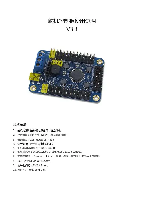
舵机控制板使用说明V3.3规格参数1. 舵机电源和控制板电源分开,独立供电2. 控制通道:同时控制32 路。
(舵机速度可调)3. 通讯输入:USB 或者串口(TTL)4. 信号输出:PWM(精度0.5us)。
5. 舵机驱动分辨率:0.5us , 0.045 度。
6. 波特率范围:9600 19200 38400 57600 115200 128000。
7. 支持的舵机: Futaba 、 Hitec 、辉盛、春天,等市面上 98%以上的舵机8. PCB 尺寸:63.5mm×43.5mm。
9. 安装孔间距:55*35.5mm。
10.存储空间:板载16M U 盘。
1)供电说明本模块电源部分是分离设计的,控制板电源和舵机电源是分开供电的,这样不会相互干扰。
a)控制板电源VSSUSB 接口和蓝色端子中的 VSS 和 GND 都可以给控制板供电,两者任选一种即可。
(VSS 的供电范围是 6.5-12V)b)舵机电源VS舵机的供电情况是根据使用的舵机而定,可以查阅舵机的相关参数,若你不了解,可以使用5V 供电。
VS输入多少付电压,给舵机的就是多少付的电压,所以必须严格匹配舵机的电压参数舵机电源输入接口为蓝色接线端子中的 VS 和 GND。
(控制板电源和舵机电源中的GND 是共用的)常规舵机的电压参数MG995、MG996 供电电压为 4.8-6.8V TR213、TR223、1501MG 供电电压为 4.8-7V TR227 供电电压 4.8-7.2V未知舵机,请给 5V 供电(标准舵机 99%都可以用 5V 供电)如果供电电压超过舵机的范围,有可能造成舵机烧坏,或者烧坏舵机控制板。
请用户谨慎操作,查看舵机的相关参数。
舵机电源的其他说明请看 11 页。
2)安装驱动驱动下载地址:/down/usc_driver.exe (全部小写)直接双击 USC_driver.exe ,点击下一步即可安装驱动。
驱动安装过程中如果出现下面的提示,请选择“始终安装此驱动程序软件”。

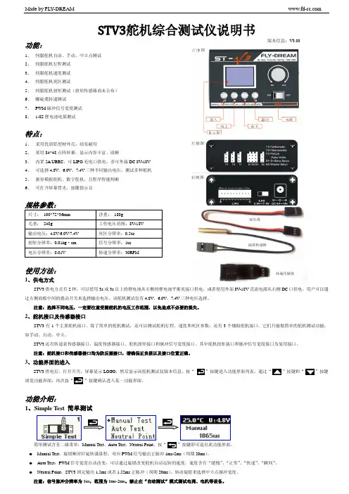
Made & Designed ByST-3500ST-3500ST3500 OPERATION MANUAL ST3500操作手冊Please read the OPERATION MANUAL before use 使用前請詳閱操作手冊ST3500ST3500 OPERATION MANUALT3500操作手冊Heating Sleeve 導熱套筒T oolholder Extension Base刀桿延長桿基座↓Round Tray刀桿隔環↓Index索 引▓Introduction產品介紹▓Standard Mode Operation標準模式操作說明Insert the tool燒結刀具Take out the tool取出刀具操作▓Custom Mode Operation自選模式操作說明▓Heating Sleeve Instruction導熱套筒使用說明▓Shrink Fit Program for Dual End Set雙頭龍燒結操作說明T wo M odes I ntroduction模式介紹Standard Mode 標準模式Heating time have been set up according to the size of shank. This setting is based on YAMAKEN's actual test results. If you would like to adjust heating seconds, please choose Custom Mode Operation.燒結時間已根據刀桿內孔徑不同設定完成。
燒結時間設定是依據山謙Move the induction coil to the properposition. (The distance from the top ofinduction coil to the top of chuck is about25 ~ 30mm)手持握把將加熱線圈移動至適合的位置(加熱頭端部至燒結刀桿鼻端距離約25~30mm)。

MyV3 RTS 用户手册前言著作权著作权 (著) 1988-2003,北京安博士信息安全技术有限公司本使用手册中的内容和程序受到著作权法和计算机程序保护法的保护.文件信息制作目的制作对象更改次数文件版本文件概要1.2.3.4.5.2标记规则[参考] 有易于用户更加方便使用的附加使用方式[注意] 使用该程序时必须注意的事项.例如无法预测的状态存在或会引起较大损失时的警告项 <屏幕名称> 在屏幕上显示的文具及框架,Windows名称.“项目名称” 在菜单上显示的各项目名称.‘文件名称’ 文件及目录路径名称技术支持及病毒咨询地址 100083北京市海淀区中关村东路18号财智大厦C座2005室公司主页 电话 06-8260-0932/33/36/38 传真 06-8260-09313海外分公司China, Beijing Rm 1701, Modern Qing Yun Building No34 BeiSanHuanXi Road, Haidian District, Beijing , P.R.C china 100086Tel : +86-10-6219-6008Fax : +86-10-6219-6003China, Shanghai No.2602 Lippo Plaza, No222Huaihaizhong Road , Luwan District Shanghai, China 200021Tel : +86-21-5396-6132Fax : +86-21-5396-6020Tokyo, Japan 6F Iijima Bldg., 2-25-2 Nishigotanda Shinagawa-ku,Tokyo, Japan 1410031Tel. +81-3-5435-8612Fax. +81-3-5487-6075Web : Http://www.ahnlab.co.jp4目录1.在开始之前 (7)1.1.用户注册及支援服务 (7)1.2.使用咨询及技术支持 (7)1.3.发现新病毒时 (8)2.MYV3 RTS (REAL-TIME SCAN)的特点及运行 (9)2.1.特点 (9)2.1.1.优点 (10)2.2.操作系统 (11)2.3.开始运行及使用菜单 (12)2.3.1.运行步骤 (12)3.掌握使用方法 (17)3.1.病毒监控信息窗口 (17)4.MYV3 RTS和WINDOWS 安全中心(XP SP2) (18)4.1.W INDOWS 安全中心(使用中) (18)4.2.W INDOWS 安全中心(不使用) (19)4.3.W INDOWS 安全中心(不是最新版本) (20)4.4.W INDOWS 安全中心(无法查找) (21)5图片目录[图2-1]开始运行按钮 (12)[图2-2]M Y V3R EAL-TIME S CAN下载屏幕 (12)[图2-3]确认安博士信赖认证窗口 (13)[图2-4]M Y V3R EAL-TIME S CAN正在运行中 (13)[图2-5]智能升级窗口 (13)[图2-6]最新引擎分析 (14)[图2-7]下载最新引擎 (14)[图2-8]程序及引擎升级 (15)[图2-9]安装V3R EAL-TIME S CAN时 (15)[图2-10]TRAY图标 (16)[图2-11]M Y V3R EAL-TIME S CAN退出通知窗口 (16)[图3-1]发现病毒 (17)[图3-2]清除病毒 (17)[图4-1]W INDOWS 安全中心(使用中) (18)[图4-2]W INDOWS 安全中心(不使用) (19)[图4-3]W INDOWS 安全中心(不是最新版本) (20)[图4-4]W INDOWS 安全中心(无法查找) (21)61.在开始之前1.1.用户注册及支援服务安博士信息安全技术有限公司()提供V3产品系列的技术支持、客户支持以及病毒咨询等针对注册用户提供多种服务.1.2.使用咨询及技术支持MyV3 Real-time Scan使用过程中,如有疑问请先参考本使用手册. 如有其他方面的咨询请通过邮件、本公司主页、电话和传真及邮箱联系我们.公司主页 客服中心负责人邮件 ***************.cn公司地址 100083北京市海淀区中关村东路18号财智大厦C座2005室公司电话 06-10)8260-0932/33/36/38公司传真 06-10)8260-093171.3.发现新病毒时如怀疑被新病毒感染时,请与安博士信息安全技术有限公司联系.如怀疑被病毒感染或者发现新病毒时,或者通过其他防毒软件发现新病毒时,请与客服中心联系后把病毒样本直接发给客服中心. 我们尽快对传送文件进行分析后,确认是否被病毒感染,如果确认为新病毒时,在最短时间内给您发送该病毒引擎,使您的损失最少化.公司主页 客服中心负责人邮件 ***************.cn北京安博士信息安全技术有限公司 100083北京市海淀区中关村东路18号财智大厦C座2005室公司电话 06-10)8260-0932/33/36/38 公司传真 06-10)8260-093182.MyV3 RTS (Real-time Scan)的特点及运行2.1.特点MyV3 Real-time Scan只要上网,就能实时监控及拦截病毒的在线专用ASP服务.针对在计算机系统上执行恶意任务的病毒和特洛伊木马等恶性程序进行防范.内载安博士有限公司的WARP引擎,可以稳定、快速查杀,MyV3 Real-time Scan是在线专用模式,并且内载安博士有限公司独有的WARP引擎,可以迅速扫描及清除国内外未知病毒及宏病毒,蠕虫, Back Orifice后门工具等恶性程序和有害性代码.可以100%查杀已发现病毒, 在国内外防病毒软件中,提供最快最正确的诊断/治疗性能.随着新型病毒的不断出现,反病毒技术也随着病毒的变化需要不断提高. 在MyV3 Real-time Scan最少1周内提供引擎升级服务, 当用户运行该服务时,自动升级为最新版本.MyV3 Real-time Scan是通过内载安博士有限公司开发的WARP引擎,可以实时监控系统. MyV3 Real-time Scan启动后,首先对当前运行的程序和内存进行扫描后,检查是否被病毒及外挂程序受感染,如被感染时自动清除。
目录目录 (1第一部分基本操作 (9第1章系统安装 (91.1系统要求 (91.2系统安装 (91.2.1安装桥梁博士V3.0 (91.2.2安装加密锁驱动程序 (121.2.3安装网络版服务器端软件 (15 第2章系统的基本介绍 (212.1系统概况 (212.2系统功能 (212.2.1系统的基本功能 (212.2.2系统的特色功能 (242.3系统的基本操作 (252.3.1图形窗口 (252.3.2数据窗口 (252.4系统的基本约定 (262.4.1单位约定 (262.4.2坐标系 (262.4.3荷载方向 (272.4.4效应方向 (282.4.5数据填写便捷格式 (28第3章系统项目的管理和操作 (29 3.1项目的意义与内容 (293.2项目组操作 (303.3项目操作 (33第4章直线桥设计计算输入 (36 4.1直线桥原始数据约定 (364.2数据准备 (364.3项目的建立 (374.4输入总体信息 (384.4.1基本信息 (394.4.2钢束参考线定义 (412 目录4.4.3估算配筋信息 (424.4.4初始状态信息 (434.5输入单元信息 (434.5.1单元的基本信息 (44 4.5.2截面特征描述 (464.5.3截面几何描述 (484.5.4附加截面描述 (494.5.5快速编辑器 (514.5.6单元编辑总结 (594.6输入钢束信息 (594.6.1数据准备 (604.6.2基本信息 (604.6.3钢束几何描述 (624.7输入施工信息 (654.7.1基本信息 (664.7.2施工荷载 (674.7.3边界条件 (694.7.4主从约束 (704.7.5全局挂篮编组 (714.7.6阶段挂篮操作 (724.8输入使用阶段信息 (73 4.8.1使用阶段基本信息 (744.8.2活荷载 (764.8.3活载的最终效应 (794.9输入优化阶段信息 (814.9.1基本信息 (824.9.2自设定目标索力 (834.10脚本文件的装载 (834.11输入数据诊断 (83第5章直线桥梁设计计算输出 (85 5.1总体信息输出 (855.2单元信息输出 (865.3钢束信息输出 (895.4施工阶段信息输出 (915.5使用阶段信息输出 (935.6优化阶段信息输出 (965.7输出文本数据结果 (975.8输出图形数据结果 (98目录3 5.9输出报表数据结果 (99 第6章斜弯桥设计计算输入 (100 6.1结构的离散 (1006.2建立项目文件 (1006.3总体信息输入 (1016.4单元信息输入 (1036.4.1单元基本信息 (1036.4.2单元快速编辑器 (1056.5钢束信息输入 (1116.6施工信息输入 (1126.7使用信息输入 (1166.8输入数据检查 (123第7章斜弯桥设计计算输出 (1247.1总体信息输出 (1247.2单元信息输出 (1257.3钢束信息输出 (1287.4施工阶段信息输出 (1307.5使用阶段信息输出 (1337.6输出文本数据结果 (1367.7输出图形数据结果 (1387.8输出报表数据结果 (138第8章设计计算工具的使用说明 (1398.1剪力计算 (1398.1.1建立抗剪计算文件 (139 8.1.2装载、输入原始数据 (141 8.1.3查看结果 (1438.2截面设计 (1448.2.1使用方法 (1448.2.2设计内容 (1458.2.3设计类型 (1488.3横向分布系数的计算 (149 8.3.1使用方法 (1498.3.2计算内容 (1508.4基础的计算 (1558.4.1使用方法 (1558.4.2计算内容 (1574 目录第9章日常工具的使用说明 (165 9.1插值计算 (1659.2图形编辑器 (1669.2.1使用方法 (1669.2.2菜单命令 (1669.2.3直线桥的绘制 (1689.2.4斜弯桥的绘制 (1699.2.5图形绘制基本操作命令 (170 9.3内嵌工具 (170第10章打印、帮助和使用教程 (171 10.1系统的打印 (17110.2系统的帮助 (173第二部分特色功能 (175第11章材料库 (17511.1系统材料和自定义材料 (175 11.2材料库的定义 (17611.3材料库的运用 (177第12章自定义截面 (18012.1前言 (18012.2自定义截面步骤 (18112.3自定义截面的脚本编辑 (183 12.4使用自定义截面 (18412.5通用截面拟合 (186第13章自定义报告输出 (191 13.1前言 (19113.2模板数据格式 (19113.3报告输出操作 (19413.4自定义报告 (20013.4.1内容索引 (20013.4.2可输出内容 (20113.4.3荷载编号 (215第14章与AUTOCAD交互 (217 14.1截面与CAD交互 (217 14.1.1从CAD导入截面 (217目录514.1.2向CAD导出截面 (219 14.2模型与CAD交互 (221 14.2.1平面杆系模型导入 (221 14.2.2空间网格模型导入 (225 14.2.3向CAD输出模型 (229 14.3钢束信息与CAD交互 (230 14.3.1从CAD导入钢束 (23014.3.2向CAD输出钢束 (232 14.4模型、钢束图纸的生成 (233 14.4.1自动生成模型图纸 (233 14.4.2自动生成钢束图纸 (236第15章调束工具 (24115.1打开调束窗口 (24115.1.1工程项目准备 (24115.1.2数据交互与窗口组成 (242 15.1.3注意事项 (24315.2调束界面操作 (24315.2.1功能区 (24315.2.2效应区 (24715.2.3图形区 (24915.3调束操作流程 (25115.3.1调束前的数据准备 (251 15.3.2完成钢束线形描述 (251 15.3.3调整钢束 (25115.4示例 (25215.4.1完成全桥建模 (25215.4.2打开调束文档 (25215.4.3输入钢束信息 (25415.4.4调整钢束 (25615.4.5重载效应 (258第16章调索工具 (25916.1打开调索窗口 (26016.1.1工程项目准备 (26016.1.2数据交互与窗口组成 (260 16.1.3注意事项 (26116.2调索界面操作 (26116.2.1功能区 (2616 目录16.2.2效应窗口操作 (26416.2.3图形窗口操作 (26616.3调索操作流程 (26716.3.1调索前的数据准备 (26716.3.2初步确定施工、成桥索力 (268 16.3.3调整施工、成桥索力 (268 16.4示例 (26916.4.1完成全桥建模 (269 16.4.2打开调索文档 (269 16.4.3调整索力 (27116.4.4重载效应 (27216.4.5调整索力 (274第17章脚本输入输出 (276 17.1前言 (27617.2脚本建立与使用 (276 17.2.1建立脚本文件 (276 17.2.2打开脚本文件 (277 17.2.3使用脚本 (27817.3数据类型的说明 (278 17.4脚本文件内容 (27817.5控制信息变量 (28017.6总体信息的输入 (280 17.6.1基本信息输入 (280 17.6.2子窗口信息 (28317.6.3钢束参考线输入 (283 17.6.4结构初始状态输入 (28617.6.5截面配筋一般信息 (287 17.7单元信息窗口 (28817.7.1基本信息输入 (288 17.7.2子窗口信息 (29017.7.3截面特征描述 (290 17.7.4截面坐标输入 (292 17.7.5附加截面描述 (294 17.7.6截面钢筋输入 (295 17.8钢束输入 (29617.8.1钢束基本信息输入 (298 17.8.2子窗口信息 (29917.8.3钢束几何输入 (299目录717.9荷载输入 (30117.9.1集中荷载 (30117.9.2均布荷载 (30217.9.3线性荷载 (30217.9.4强迫位移描述 (303 17.10施工信息的输入 (30417.10.1基本信息输入 (30617.10.2子窗口信息 (30617.10.3竖向预应力描述 (30717.10.4永久荷载 (30817.10.5临时荷载 (30817.10.6施工活载1 (30917.10.7施工活载2 (31017.10.8施工活载3 (31017.10.9移动荷载描述 (31017.10.10边界条件 (31117.10.11主从约束描述 (31317.10.12阶段挂篮操作 (31317.10.13索力设定 (31517.10.14全局移动荷载和挂篮编组 (316 17.11使用信息的输入 (31817.11.1基本信息的输入 (31917.11.2子窗口信息 (31917.11.3自定义组合 (32017.11.4温度荷载 (32117.11.5不均匀沉降 (32217.11.6活载 (32317.11.7特殊荷载描述 (325 17.11.8特殊车列 (32617.11.9轻轨荷载信息 (328 17.11.10ZK活载集度定义 (328 17.11.11横向分布调整系数 (330 17.11.12折线横向分布系数 (331 17.11.13影响有效区域设定 (334 17.12优化信息的输入 (335 17.12.1基本信息输入 (335 17.12.2子窗口信息 (33617.12.3外力荷载信息 (336 17.12.4自设定目标索力 (3378 目录17.13常见脚本错误及修改 (337 17.13.1类型错误 (33717.13.2不正确的结束脚本: (339 17.13.3变量错误 (34217.13.4控制信息错误 (34317.13.5空格引起的错误 (34417.14脚本数据与界面数据的关联 (345 17.14.1两种输入方式下数据的相似性: (345 17.14.2两种输入方式的综合使用 (345第三部分规范计算 (349第18章规范计算需注意的问题 (34918.1公共部分 (34918.2公路04规范 (35018.3中铁99规范 (352附录A系统材料名称 (354A.1混凝土材料名称 (354A.2普通钢筋材料名称 (355A.3预应力钢筋材料名称 (356A.4钢材材料名称 (356附录B图形编辑操作 (357B.1功能区别 (357B.2操作应用 (357第1章系统安装9第一部分基本操作第1章系统安装1.1 系统要求1.系统模块:●系统包含了DBMAIN.EXE、DBINPUT.DLL等多个模块,分别完成特定的功能,程序安装后,这些文件全部安装在安装目录下,不得随意复制或移动,否则运行中将因不能随时找到相应模块文件而导致出错。
1 系统初始配置在DM/MS以及EC/DC设备加入VM3.0系统管理前,需要进行一些基本配置,本章介绍了DM/MS 以及EC/DC等的初始配置。
您按照本章的介绍完成各款服务器以及终端设备的初始配置后,再通过VM3.0客户端软件完成相应设备的添加,添加后即可正常上线。
1.1 系统典型组网图1-1典型配置组网图1.2 DM/MS的基本配置安装完DM3.0/MS3.0软件后,请登录Web页面确认通信参数配置正确,以便与VM3.0能正常通信。
具体操作步骤如下:(1) 客户端计算机上打开Web浏览器,在地址栏中输入服务器的IP及端口号,如下图1-2所示,(2) 在登录对话框中输入管理员密码admin,点击<登录>按钮,即可进入Web页面。
登录系统后,进入[系统配置/通信参数配置]页面,确认服务器IP地址(VM3.0/ISC3000-E的IP地址)是否正确,其他参数保持默认值即可。
其他相关内容可参见联机帮助。
登录DM和MS需要使用IP+端口方式:●登录DM,需要在浏览器地址栏中输入DM IP:8080●登录MS,需要在浏览器地址栏中输入MS IP:8081图1-2登录服务器1.3 VX500的基本配置通过登录Web页面确认通信参数配置正确,以便与VM3.0能正常通信。
具体操作步骤如下:(1) 客户端计算机上打开Web浏览器,在地址栏中输入服务器的IP,按回车键。
(2) 在登录对话框中输入管理员密码admin,点击<登录>按钮,即可进入Web页面。
登录系统后,进入[系统配置/通信参数配置]页面,检查服务器IP地址是否正确即可,其他参数保持默认值即可。
配置VX500的阵列需要在VM3.0客户端上进行,具体操作请参见“添加VX500”。
图1-3登录VX5001.4 VX1500基本配置登录Web页面,完成VX1500的基本配置后,即可与VM3.0能正常通信。
VX1500出厂管理口(100M网口)默认IP地址为192.168.0.1。
ST - III Series POWER SUPPLIESUSER MANUALIntroductionThese instructions detail the installation and operation requirements for the ST20-III & ST35-III power supplies. These have been designed for operation in RV’s providing a DC power system, with optional battery back up.The units operate from 240Vac and provide an isolated 13.65Vdc output at 20A and 35A respectively for powering the load and charging of batteries. All the necessary protection and operating features for the load and batteries are provided. An optional DC input is also provided to enable charging of batteries and powering of the load from an external +13.8V DC power source. The units are fully enclosed ready for direct wall mounting. All connections are at the rear of unit providing convenient wiring and installation. User access to all load and battery fusing has been provided from the front of the unit.OperationSafety: Refer to the installation section before operating. Correct installation is the most critical factor in ensuring the safe use of the power supply. If every consideration of these instructions has been satisfied the power supply will be safe to operate.If the AC supply cord is damaged it must be replaced by the manufacturer, its service agent or similarly qualified persons in order to avoid hazard.The unit is rated to charge a single 12V (up to 6 cells) lead acid battery at 100Ahr Capacity. Functional Diagram:AC/DC Power Supply: This provides an isolated 13.65Vdc output for powering of the load and float charging of the battery. Battery current is sensed and monitored by the power supply to ensure that the maximum charging current is not exceeded.Battery Features: The power supply provides full battery management as per the following.The power supply is a four stage battery charger with Boost (VBoost = 14.05V), Float (VFloat = 13.65V), Store (VStore = 13.25V) and Trickle charge modes to ensure long battery life.Battery Charging current is limited to a maximum of 10A (ST20-II) and 15A (ST35-II). This provides optimum life for the batteries.To charge at the maximum battery charge current above, ensure the load current plus battery current is equal or less than the maximum output current. The charging current will be reduced in situations where the difference between the rated output current and the load current (the available charging current), is less than the maximum charging current.Also note that the battery current sense is provided in the “Batt +ve” battery output. For this feature to work, the load “+ve” and battery “Batt +ve” should not be cross connected. (Appliances should not be connected to both the “Batt +ve” and “+ve” terminals of the power supply. Appliances should be connected to the “+ve” and “-ve” load terminals).Low Voltage Disconnection of the batteries is provided to prevent deep discharge of the battery. Automatic reconnection occurs when battery voltage recovers.Battery Current Drain is less than 2mA.Trickle Charge to the battery is always present. When the battery voltage is below the LVD (Low voltage disconnect) re-connect voltage (<10V and the mains power or auxiliary power is available, the battery will be charging at 0.8A. When the battery voltage is sufficient (>10.5V for first power up, 11.5V and 11.7V for subsequent reconnection with and without mains respectively) the LVD will connect the battery and allow float charging at 10A/15A (ST20-II/ST35-II). The Trickle Charge feature is provided to allow “very” flat batteries to be charged at a rate, which will extend their life.Remote Battery Isolate Switch: The ST-III series power supplies allow for connection to a remotely positioned switch that provides a manual disconnection of the battery from the loads and the main charger. When the switch contacts are closed, the battery will be isolated from the loads. NOTE: When the battery is isolated from the loads using the battery isolate switch it will NOT charge at the 10/15 A rate even if the mains is connected to the power supply. In this condition it will ONLY charge at the Trickle charge rate.Front Panel Indicators: The ST-III series power supplies have 3 indicators visible on the front fascia.Mains(GREEN) – is illuminated when mains power is present.Battery(ORANGE) – is illuminated when the battery is connected to the loads.Fault(RED) – is illuminated when there is a fault with the power supply.Battery fuse Blown1Battery connected reverse polarity2Shut down condition (UV and OT)3Main PCB micro controller malfunction4Notes1.Flashing 1s ON, 1s OFF.2.Solid ON.3.Flashing 1s ON, 1s OFF, with no battery connected the power supply may be in hiccupmode which will cause the indication to flash with random duty cycle and frequency.4.Fault Led= Solid On, All other leds = OFF, irrespective of actual mains or LVD status. Auxiliary Power Input: The power supply terminal “Aux In +VE” provides an alternative option for powering of the load and float charging of the batteries when mains voltages are not present. This input is to be powered by a suitable +12V system. (i.e. CAR). The voltage of the auxiliary power source should not exceed 14.8 volts.When operating via the external input, current and voltage control for the battery must be provided from the external source. The ST20-II/35-II does not provide battery current limit or voltage control when operating in this configuration. Trickle Charge is still functional when powered through “Aux In +VE” terminal of power supply.Suitable fuse protection must be provided for this input. A fuse rating not exceeding 20 Amps for ST20-II and 30 Amps for ST35-II must be used.Solar power should be connected directly across the battery terminals with a voltage regulator in series. A solar panel voltage regulator with maximum output voltage not exceeding 14.8 volts must be used at all times. Failure to use a voltage regulator may result in power supply damage. Generator 12 volt outputs should not be connected across battery terminal whilst battery is connected to power supply or connected to the “Aux In +VE” terminal of power supply. Serious power supply damage or internal explosion may occur. If a flat 12 volt battery has to be charged using the generators 12 volt output, it should first be disconnected from the power supply. Once battery has being charged it can then be reconnected to power supply.Power supply unit should only be powered from either 240VAC mains or Auxiliary Power (Auxiliary Power also includes solar power) but not both. Failure to do so may result in damage to power supply.Protection: the power supply provides automatic protection for overload including short circuit, over-voltage, over-temperature and reverse connected battery. In such instances the Fault indicator will illuminate and the power supply will shut down. It will attempt to automatically restart every 5 seconds until such case that the fault is removed.Fusing: Each load circuit and the battery have been fused to provide fault protection and discrimination. Refer to servicing section for maximum fuse ratings.InstallationHost Equipment: The host equipment must ensure that access to the unit (other than the front panel) by the user is prevented.Personnel: Installation is to be carried out only by suitably qualified personnel.Ventilation: Provide a minimum of 80mm clearance above, below and behind the unit. The final enclosure must also provide adequate ventilation to the outside world (or larger internal cavity) to prevent the build up of hot air. Failure to provide adequate ventilation will mean the unit may prematurely trip thermal shut-down. A minimum ventilation of 20,000mm2 to the outside world must be provided.Mechanical and Mounting:After mounting unit, clip on the front fascia (ensure that all locking clips have engaged) and secure with screw located inside the fuse panel door.Orientation: The unit is to be installed with the front fascia in a vertical plane. Failure to do this will cause premature temperature shut-down.Wiring UpMains: This is pre cabled and fitted with AS/NZ mains plug ready for connection to internal GPO. Ensure that the connection to the mains supply is in accordance with the national wiring rules, and that the earth connection is installed.Load, Battery and External DC Input Connections: Connectors are 0.8 x 6.3mm QC tabs. Use mating QC connector suitable for cable size. Connector pin-out is shown below.Cabling sizes: DC cables must be sized to carry the maximum full load current and not exceed the system volt drop requirements. The following cable sizes are recommended.Where cables pass through any part of a metal panel or cover, ensure that a cable gland or bush is fitted to the hole.Battery Connection Procedures:Battery should be connected as per the following steps.Turn power supply off and all 12 volt equipment connected to power supply.Connect positive battery terminal to “Batt +VE” power supply terminal.Connect negative battery terminal to “Batt -VE” power supply terminal or negative chassis ground.If battery is connected to chassis, ensure a connection exist from chassis to “Batt –VE”terminal of power supply.Battery Disconnection Procedures:Battery should be disconnected as per the following steps.Turn power supply off and all 12 volt equipment connected to power supply.Disconnect negative battery terminal connection to “Batt –VE” power supply terminal or negative chassis ground.1.Disconnect positive battery terminal to “Batt +VE” power supply terminal.BatteriesWhen using batteries with this product always consult with the battery manufacturer for a detailed description of the installation, use and maintenance of the battery.Ensure battery has been charged for several days before a major camping trip (Leave the power supply on for at least 2 – 5 days with battery connected).This product is suitable for charging 12V-Sealed Lead-Acid (SLA) batteries including Valve-Regulated Lead-Acid (VRLA) batteries both Absorbed Glass Mat (AGM) and Gel batteries. One or two batteries with max.100Ah capacity each can be charged. Charging current is limited to 10A (ST20-II) and 15A(ST35-II).ServicingPersonnel: This product contains hazardous voltages and energy hazards, which can result in death or injury. Only properly qualified service personnel may service it.There are no internal user serviceable parts. Only the fuses located in the “fuse panel” located on the front panel are serviceable.Isolate mains power, Vext and battery before servicing.Replacement of Fuses: Only the DC output Load and Battery fuses may be replaced.Fuse ratings: Load fuses 20A max, Battery Fuse 35A max.Fuse types: 32V Automotive Bussmann ATC series or Littelfuse 257 series or equivalentSpecificationInput Voltage:ST20-II & ST35-II: 230 – 240Vac nominal, ±10%, 50/60Hz.The power supply will withstand a 5 minute, +15% surge on themaximum nominal voltageInput Surge:< 40A (cold start)Hold-up Time:> 10mS at full load current and over nominal input voltage operatingrangeOutput Current:ST20-II: 20A Continuous (load + battery current)ST35-II: 35A Continuous (load + battery current)Factory Set Voltage 13.65V +/- 0.1V (Vfloat)Load Regulation:< 2%Output RippleVoltage:< 150mVOver VoltageProtection:< 17VOver Current Protection ST20-II: 20A to 25A (load + battery current) ST35-II: 35A to 38A (load + battery current)Battery Current Limit10A ± 1A (ST20-II)15A ± 1A (ST35-II)BatteryConnect/Disconnect Connect: 10.50 ± 0.2V (Input Mains not present) and first power up Connect: 11.70 ± 0.2V (Input Mains not present and not first power up) Connect: 11.50 ± 0.2V (Input Mains present)Disconnect: 10.0 ± 0.2VBattery TrickleCharge0.8A Battery Drain< 2mA. Efficiency:> 84%Cooling Fan Operation ST35-II Only.Cooling fan on temperature of Transformer: 95C + 3 degrees. Cooling fan off temperature of Transformer: 75C + 3 degrees.Ambient0O C – 50O CWeight:< 2kgStandards Safety: AS/NZS 60335-1, AS/NZS 60335-2-29 & AS/NZS 61558EMC CISPR 22 class ACompliance:ERAC+ACMA (RCM)Battery ManagementTo maintain the battery in a good state of health an intelligently controlled charging algorithm is used. The purpose is to ensure that the correct voltages are applied to the battery terminals at the appropriate times throughout it’s usage cycle.To prevent corrosion on the battery positive plate due to continuous float charging current (VFloat = 13.65V), the unit utilises a storage mode voltage (VStore = 13.25V) when no activity on the battery is detected. This extends the battery life. During store mode, the unit exits to boost mode (VBoost = 14.05V) for 15 minutes every 24hrs to maintain charge in the battery. If battery activity is detected during store mode it exits automatically into float mode.For any decision making involving the “loss of mains” detection there is a 2 minute mains debounce period where there must be no mains signal present on the mains detect input for the “no mains” signal to be valid.A detailed description of the operational requirements for the charging algorithm is describedbelow:N/A Microcontroller first powerup.Initial application of powerto the microcontrollereither from 240VAC mainsinput or connection of abattery to the battery input (Includes Auxiliary power).VfloatVfloat (No Mains Input)Mains input detected afterloss of mains for less than1 hour.Float charging mode withmains input voltagedetected (set 24 hourtimer).VfloatVboost Mains input voltage wasdetected for more than 15minutes.Float charging mode withmains input voltagedetected (set 24 hourtimer).VfloatVfloat No mains input voltage isdetected.Float charging mode withno mains input voltagedetected (set 1 hour timer).Vfloat (Nomains input)Vstore No mains input voltage isdetected.Float charging mode withno mains input voltagedetected (set 1 hour timer).Vfloat (Nomains input)Periodic_Vboost No mains input voltage isdetected.Float charging mode withno mains input voltagedetected (set 1 hour timer).Vfloat (Nomains input)Vfloat (No Mains Input)Mains input voltage wasdetected after being absentfor more than 1 hour.Loss of mains, boostcharging mode, active afterresumption of mains inputsupply (set 15 minute boosttimer).VboostVboost (No Mains Input)Mains input voltage wasdetected (this conditionmust also reset the 15minute boost period).Loss of mains boostcharging mode, active afterresumption of mains inputsupply (set 15 minute boosttimer).VboostVboost No mains input voltage isdetected.Boost charging mode whileno mains is detected.Vboost (NoMains Input)Vfloat Mains input voltage waspresent for more than 24hours.Battery storage mode (set24 hour timer).VstorePeriodic_Vboost Periodic boost voltagetimer has timed out.Battery storage mode (set24 hour timer).VstoreVstore Battery storage mode timerhas timed out.Periodic boost mode (set15 minute timer).Periodic_VboostBattery Charging Voltage Over TimeTimeST–III Series Power Supplies USER INSTRUCTIONSElectromagnetic compatibility (EMC)Electromagnetic compatibility (EMC) is defined as “the ability of a device, equipment or system to function satisfactorily in its electromagnetic environment without introducing intolerable electromagnetic disturbance to anything in that environment”.Switch-mode power supplies are good generators of EMI and as such care needs to taken during their designs to limit their emissions. Requirements of the local regulator (ACA) limit the emissions to protect the frequency spectrum. Limits are set down in standards such as EN55022 for radiated and conducted emissions. However, these limits are not satisfactory for devices in close proximity (<3m) and as such do not guarantee that the power supply will not cause interference with devices such as TV’s or radios.The ST20-III/35-III have been designed with equipment interoperability in mind. The emissions are in the order of 10 – 100 times below the regulator requirements (this is expressed in dB (µV)) and greatly reduce the likelihood of causing interference with Radios and TV’s located in close proximity.However, care still needs to be taken with the routing of cables and placement of the unit with respect to appliances. Small emissions can still cause interference. If interference is present, then locate cables from the power supply away from appliance so far as possible and also locate the power supply away as far as practical.Page 11 of 11Issue D。
Découvrez si le Thermostat Intelligent fonctionne avec votre système de chauffageCe guide est uniquement valable pour la France et la BelgiqueGuide de compatibilité pour le Thermostat Intelligent V3+V2.3 Nov 20210195_AChaudières et interfacesLa plupart des chaudières fonctionnent selon deux modes. Le premier appelé contact sec, relais, marche/arrêt ou encore tout ou rien (ToR) active à 100 % votre chaudière lorsqu’une demande de chaleur est faite, et à 0 % lorsqu’il n’y a plus dedemande. Le second mode, l’interface modulante (ou digitale), a la possibilité de réguler la puissance de la chaudière pour chauffer selon l’intensité de la demande de chaleur.Interfaces• Si votre thermostat actuel utilise l’interface contact sec (relais) pour contrôler un système de chauffage à eau (hydronique), tado° pourra toujours le remplacer.•En utilisant une interface modulante, tado° offre un contrôle plus économique de votre chaudière, et un thermostat correspondant à une meilleure classe ErP d’économie d’énergie (classe VIII).• tado° est unique car compatible avec 95% des systèmes de chauffage central (ayant une interface modulante telle que Opentherm, BUS Vaillant, BS BUS, KM BUS Viessmann ou exploitant l’interface contact sec) mais également des pompes à chaleur. Veuillez trouver à la fin de ce document la liste des chaudières compatibles avec tado° et leurs interfaces.Interface contact secAvec un système relais, la chaudière est activée à 100 %ou désactivée en fonction de la demande de chaleur.Interface modulanteAvec un système de chauffage à interface modulante, la chaudière module l‘apport de chaleur fourni en fonctionde l’importance de la demande de chaleur faite.Légende:= température de la pièce= température demandée par l’utilisateur= puissance de la chaudièreGuide de compatibilité pour le Thermostat Intelligent V3+Système de chauffage collectif et chauffage urbain ou à distance• tado° s’adapte aux systèmes de chauffage collectif et réseau de chaleur en remplaçant le thermostat filaire actuel par un Thermostat Intelligent tado°.•Si vous n’avez pas de thermostat filaire dans votre logement, il est possible d’installer des TêtesThermostatiques Intelligentes pour contrôler desradiateurs à eau équipés d’une vanne thermostatique.Pompe à chaleur et climatisation•Si votre pompe à chaleur assure uniquement le chauffage et est contrôlée par un thermostat filaire, celle-ci peut fonctionner avec le Thermostat Intelligent tado°. Veuillez vérifier la compatibilité de votre système grâce au tableau que vous trouverez à la page suivante.•Si votre pompe à chaleur ou climatisation fonctionne avec une télécommande utilisant des signaux infra-rouge et affiche les paramètres actifs du climatiseur, votre pompe à chaleur est compatible avec le Contrôle Intelligent de la Climatisation tado°.Plancher chauffant•Un thermostat contrôlant un plancher chauffant à eau peut presque toujours être remplacé en suivant les instructions envoyées par tado°. Le refroidissement par chauffage au sol n‘est pas supporté par tado°.•tado° n’est pas compatible avec les planchers chauffants électriques.Système avec réseau de résistance, radiateur électrique, sonde extérieure et panneaux solaires• tado° n’est pas compatible avec les systèmes utilisant un réseau de résistance ou un fil pilote.• tado° n’est pas compatible avec les radiateurs électriques.• Si votre système est équipé d’une sonde de température externe, celle-ci n’aura pas d’impact sur la compatibilité de tado° ou lors de l’installation.•tado° ne peut pas toujours fonctionner lorsque des panneaux solaires thermiques font partie de votreinstallation. Veuillez nous contacter si vous êtes dans cette situation afin que l’on puisse confirmer la compatibilité de votre système.Tableau de compatibilité des chaudières les plus courantes•La liste ci-dessous est basée sur des systèmes avecun seul circuit de chauffage. Si votre chaudière alimente plusieurs circuits de chauffage, veuillez contacter notre support technique et nous fournir autant d‘informations que possible sur votre installation de chauffage actuelle.Si votre marque ne figure pas dans cette liste, vous pouvez nous contacter pour vérifier si votre système spécifique est compatible avec tado°.Attention : bien que tado° soit compatible avec 95% des chaudières, certaines ne supportent pas tado° actuellement. Dans certains cas, la compatibilité peut dépendre de l‘ensemble du système de chauffage (thermostat, contrôleur, panneaux solaires …). Veuillez noter que toutes les informations indiquées dans ce guide sont à titre indicatif et non exhaustives. Informations supplémentaires - installation• Pour procéder à l’installation des appareils, veuillez télécharger l’application tado°, enregistrer vos appareils tado° et indiquer les appareils qu’ils remplacent. Vousrecevrez ainsi des instructions, étape par étape, pourinstaller votre système.• Les guides pour installateurs professionnels se trouvent sur /professional-manuals.。
INSTALLATION MANUAL FOR USING YOUR THROTTLE V3Version 1.6.402 33.A ug.20176w w w.c o k c p f it o r y o u .c moTo r s t e n Mül l e rInstallation manual for using your TQThank you for purchasing the motorized version V3 of our new COCKPITFORYOU 737throttle quadrant. It has been assembled and tested with the greatest care. To makethe installation as convenient as possible for you, we tried to describe the installationprocess in great detail. Should you still experience difficulties with the setup oroperation of your throttle quadrant, please do not hesitate to contact us via email orphone. In the near future we will release a video setup tutorial in addition to thismanual that will guide you through all the necessary steps.We hope you will have as much fun flying your new TQ as we had engineering andassembling it.1.Before getting started•download CFY_TQ.zip•download vJoy.rar2. Connecting your ThrottlewYour motorized butterfly comes with 1 Ethernet portand 1 female PC power supply.PC power supply (100-240V / 50-60Hz)Ethernet cable:Plug in the Ethernet cable into a free port of an Ethernet switch.Minimum requirement for switch is 100 Mbit.3. installation software1.Create new folder "CFY" on drive C:2.Extract CFY_TQ.zip to C: CFY3.In the folder C:\CFY double click the file "vJoy_216_150815". Installationmay take 5 minutes. Restart computer. If installation seems to be haltedafter approx 5 minutes you can restart computer.4.In the folder C:\CFY double click the file "setup"Change the installation folder in "C: CFY"Press “Next” and follow installation instructionsPress “Understood”The calibration is Carried out (at first start)The "TQ V3" is ready5.Start your flight simulatorThe "TQ V3" connects to your flight simulator 6.Start your AddOn SoftwareNone or “TQ V3” connects to proSim737 or SimAvionics or PM 7.Sign the Trim button on theYoke (Soon automatically)•Open FSUIPC, select“Buttons + Switches”•Press the Nose up trim switch on your yoke •Check the …Select for FS control“ box •Select “Offset Word Set” from the list•Set the first offset to x9093 and the parameter to 2The Control sent whenthe button is released:•Sele ct “Offset Word Set” from the list•Set the first offset to x9093 and the parameter to 0•Press “OK” to save these changes•Open FSUIPC, select “Buttons + Switches”•Check the “Select for FS control“ box•Select “Offset Word Set” f rom the list•Set the first offset to x9093 and the parameter to 1The Control sent when the button is released:•Select “Offset Word Set” from the list•Set the first offset to x9093 and the parameter to 0Press “OK” to save these changesAll automatically created joystick assignmntin FS deleteAdvanced settings:FS2004 without AddOn => no adjustments necessary / FSUIPC must be installedFS FSX without AddOn => no adjustments necessary / FSUIPC must be installedFS P3D without AddOn => no adjustments necessary / FSUIPC must be installedFS XPlane without AddOn => no adjustments necessary / XPUIPC must be installedPM => no adjustments necessary / FSUIPC must be installed IFly => see item 11 / FSUIPC must be installedSim-Avionics => see item 12 / FSUIPC or XPUIPC (XPlane) must be installed PMDG NGX => see item 13 / FSUIPC must be installedProSim737 => see item 14 / FSUIPC must be installed11.For IFlyIFly to FSUIPC installed.12. For Sim-AvionicsSim-Avionics Setup withCockpit For You ThrottleAn FSUIPC connection is require, so the CFY controller software should either be run on the FS computer, or run on a remote computer with WideClient running.Sim-Avionics Server Configuration1) FSUIPC_IO.INISet Multi Function OffsetMULTI_FUNCTION=53FERemove 5418 offset from PARKING_BRAKE=5418[FSUIPC_INPUTS]PARKING_BRAKE=ENGINE_L_FUEL_CONTROL_SWITCH=5452ENGINE_R_FUEL_CONTROL_SWITCH=5453Add Autothrottle output offsets[FSUIPC_OUTPUTS]COMMANDED_THROTTLE_L_POSITION=53E0COMMANDED_THROTTLE_R_POSITION=53E2THRUST_REF_MODE=53E42) Control Panel TabEnable FSUIPC Outputs ON3) Flight Controls 1 TabParking Brake External OFFFlaps External OFFGear External ONElevator Trim via FSUIPC OFFToe brakes release Parking Brake OFFEnable Simple Braking OFF4) Flight Controls 2 TabMain Throttles FDS Pro Throttle/Sys Controller Axis/SIOCReversers SIOC / Offsets 52DA and 52DCCFY FS FSUIPC oftwareConfigConfigurationuration1) FSUIPC > Axis AssignmentAdd "Parking Brake" to Brake AxisDetect Brake Axis“Control sent when range entered” = Parking BrakeUp OFFDn ONFrom = 95% of brake pedalTo = 100% of brake pedal2) FSUIPC > ButtonsTrim Up Offset Word Set x90931Repeat ONOffset Word Set x9093Trim Down Offset Word Set x90932Repeat ONOffset Word Set x9093 013. For PMDG_NGXCurrent FSUIPC4 version! As of today: 4,949 FSUIPC4 Current SimConnect version!Configuring the PMDG iniopen Windows Explorer• openComputer , DriveFSX,• open folder "PMDG"• open folder "PMDG 737 NGX"( w here F SX i s i nstaled ) ,•open" 737N GX_Options.ini"•Writing at the end of the text followingthis:[SDK]EnableDataBroadcast=1Please check carefullyThe text mustbe written exactlyIn small andcapital letters Be sureThe text must be written exactlyIn small and capital letters Ensure•Save and close the file14. For ProSim737Setting in ProSim737 Config / DriversGeneric COM port/TCP diver => Enabled“Sit back relax and enjoy your flight.“This is it. By now your 737 throttle quadrant should be up and running. In case you have any further questions or you are experiencing difficulties, please do not hesitate to contact us via email or phone.Torsten MüllerBerlin, Germany 2017。
VersaSTAT 3 Hardware ManualVersaSTAT 3 Electrochemical System 1. INTRODUCTION1.1. HARDWARE1.2. POTENTIOSTATIC CIRCUITRY1.2.1. Potentiostatic mode1.2.2. Galvanostatic mode1.3. Software1.4. Polarity Convention1.5. Inspecting Your New Instrument1.6. Maintenance, Service, and Support1.7. About this manual2. SAFETY AND COMPONENT PLACEMENT2.1. Safety Considerations2.1.1. Line Voltage Settings and Fuses2.1.2. Defects and Abnormal Stresses2.2. Component Placement2.2.1. Ventilation2.2.2. Radio Frequency Interference2.2.3. Transient Sensitivity3. INSTALLATION3.1. Enabling the USB port on your PC3.2. Connectors and Indicators3.2.1. Rear Panel3.2.1.1. INPUT POWER3.2.1.2. USB3.2.1.3. SYNC ADC INPUT3.2.1.4. DAC OUTPUT3.2.1.5. AUXILIARY INTERFACE3.2.2. Front Panel3.2.2.1. CELL CABLE3.2.2.2. INDICATORS3.3. Connecting to the PC and Cell3.3.1. Connecting to the PC3.3.1.1. INSTALLING THE USB DRIVER3.3.2. Connecting the Cell4. SPECIFICATIONS AND PINOUTS4.1. Electronic Specifications4.1.1. System Performance4.1.2. Power Amplifier4.1.3. Voltage Control4.1.4. Current Control4.1.5. Differential Electrometer4.1.6. Voltage Measurement4.1.7. Current Measurement4.1.8. iR Compensation4.1.9. Potential/Current Control4.1.10. Impedance Specifications (if option available)4.2. Physical and Power Specifications4.3. Standard Environmental Conditions4.4. AUXILIARY INTERFACE Pinouts4.5. CELL CABLE Pinouts5. AVAILABLE OPTIONS5.1. 2A High Current Option5.2. FRA Option5.3. Advanced Auxiliary Interface Option5.4. Power Booster Options6. WARRANTYAPPENDIX 1 – VersaSTAT 3 External Power Booster ConnectionsSafety Instructions and SymbolsThis manual contains up to three levels of safety instructions that must be observed in order to avoid personal injury and/or damage to equipment or other property. These are:DANGER Indicates a hazard that could result in death or serious bodily harm if the safety instruction is not observed.WARNING Indicates a hazard that could result in bodily harm if the safety instruction is not observed.CAUTION Indicates a hazard that could result in property damage if the safety instruction is not observed.Please read all safety instructions carefully and make sure you understand them fully before attempting to use this product.Cleaning InstructionsWARNING: Using this instrument in a manner not specified by the manufacturer may impair the protection provided by the instrument.To clean the instrument exterior:•Unplug the instrument from all voltage sources.•Remove loose dust on the outside of the instrument with a lint-free cloth.•Remove remaining dirt with a lint-free cloth dampened in a general-purpose detergent and water solution. Do not use abrasive cleaners.CAUTION: To prevent moisture inside of the instrument during external cleaning, use only enough liquid to dampen the cloth or applicator.•Allow the instrument to dry before reconnecting the power cord.1. INTRODUCTIONThe VersaSTAT 3 (Figure 1), teamed with the VersaStudio software package, comprises a simple, flexible, and extremely powerful system for performing a wide range of electrochemical techniques. The VersaSTAT 3 is a potentiostat/galvanostat with an optional frequency response analyzer (FRA) contained in a single unit. It is controlled from any suitably equipped PC by a Universal Serial Bus (USB) interface using the VersaStudio electrochemistry software package.Figure 1. VersaSTAT 31.1. GeneralThe host computer provides memory, data processing, input-output, and interface capabilities. The VersaSTAT 3 electronically controls the measurement under the direction of the software and parameter values entered from the host computer. The computer must be equipped with a USB port, and the operating system must support the USB interface.1.2. Hardware CircuitryThe VersaSTAT 3 circuitry includes:•Two 16-bit digital-to-analog converters (DACs) for versatile waveform generation.•Three 16-bit analog-to-digital converters (ADCs) to measure current (I), potential (E), SYNC ADC INPUT.•An onboard microprocessor to perform the experiment defined by the operating software. •Onboard memory to store the programmed parameters and data point values.The VersaSTAT 3 operates with VersaStudio in either the potentiostatic or galvanostatic mode, described below.1.2.1. Potentiostatic modeIn this mode, the VersaSTAT 3 controls the potential at the working-sense electrode with respect to the reference electrode (see Figure 2). The counter electrode is driven to the potential required (consistent with the + 12 V compliance of the control amplifier) to establish the desired working potential. The range over which the working electrode potential can be controlled is + 10 V.Figure 2. Potentiostat-Mode Block Diagram1.2.2. Galvanostatic modeIn galvanostatic operation, the VersaSTAT 3 controls the current between the counter and working electrodes at the specified fraction of the selected current range (up to the maximum of the current range; see Figure 2). The counter electrode is driven to the potential required (consistent with the + 12 V compliance of the control amplifier) to establish the desired cell current. The reference electrode is not used in the control loop, but is usually used to measure the potential at some point in the electrochemical cell relative to the working-sense connection point.Figure 3. Galvanostat-Mode Block Diagram1.3. SoftwareThe VersaSTAT 3 is fully compatible with the VersaStudio software only. The VersaSTAT 3 will not operate with any other software other than that specified in this manual or the most recent documentation available on the web site (). Likewise, the VersaSTAT 3 does not have an open command set to allow user programming outside of the VersaStudio software. The software is designed specifically to work with Windows 2000 and Windows XP, but it is highly recommended that XP be used.1.4. Polarity ConventionThe VersaSTAT 3 hardware follows the American polarity convention. (Positive current is cathodic; that is, a current is defined as positive if reduction is taking place at the working electrode. Negative current is anodic; that is, a current is defined as negative if oxidation is taking place at the working electrode. If the working electrode is driven positive with respect to the equilibrium potential, the resulting current is anodic. If the electrode is driven negative with respect to the equilibrium potential, the resulting current is cathodic.)In complex electrochemical systems, there might be more than one equilibrium system. Where this is the case, either polarity with respect to the equilibrium potential could give rise to anodicor cathodic current, according to the systems’ characteristics.1.5. Inspecting Your New InstrumentAs soon as you receive your new VersaSTAT 3, inspect it for shipping damage. If any damage is noted, immediately notify Princeton Applied Research and file a claim with the carrier. Save the shipping container for possible inspection by the carrier.WARNING: If your instrument has been damaged, its protective grounding might not work. Do not operate damaged equipment! Tag it to indicate to a potentialuser that it is unsafe to operate.1.6. Maintenance, Service, and SupportThe VersaSTAT 3 has been designed for optimum reliability and requires no periodic maintenance. There are no user-serviceable parts in this instrument. Breaking the seal by opening the cover will void your warranty! Contact the factory service department or the affiliate in your area if your unit needs service (see the Warranty in Section 5. for more information).Remember that our worldwide staff continues to support you after you have purchased your instrument. We provide top quality service, applications support, and a variety of helpful information in the form of application notes, technical notes, and training materials. For more information, visit our website at .1.7. About this manualChapter 2 describes recommended safety precautions for operating this instrument, including the provision of adequate ventilation. It also tells how to deal with transients on the power line, and discusses the unlikely possibility of the instrument causing radio frequency (RF) interference.Chapter 3 shows how to set up the hardware. It describes the functions of the connections and indicator lights, and shows how to connect the VersaSTAT 3 to the host computer and test cell.Chapter 4 gives the physical and electrical specifications of the VersaSTAT 3 including the AUXILIARY INTERFACE connector pinouts.As noted above, the VersaSTAT 3 is completely computer controlled; operation and experimental procedures are covered in the software section of this manual.2. SAFETY AND COMPONENT PLACEMENTThis chapter lists safety precautions for use when operating the VersaSTAT 3; please read them. There are suggestions for system component placement and information on possible RF interference and transient sensitivity.2.1. Safety Considerations2.1.1. Line Voltage Settings and FusesThe VersaSTAT 3 has a Corcom™ Power Entry Module on the left side of the rear panel. The Corcom module (pictured below) contains the power connector and two line fuses. The VersaSTAT 3 automatically detects the correct line voltage and frequency, so there is no line voltage changes required in the Corcom.The VersaSTAT 3 is supplied with the line voltage fuses in place, as well as extra fuses supplied with each unit. For fuse replacement:•For 100 – 120 Vac line voltages, use a 2.0 A T (slow-blow) fuse (Littlefuse® type 213, 5 x 20 mm or equivalent).•For 220 - 240 Vac line voltages, use a 1.0 A T (slow-blow) fuse (Littlefuse® type 213, 5 x 20 mm or equivalent).Caution: Do not use makeshift fuses or short-circuit the fuse holdersTo replace a fuse:1.Disconnect the instrument for the ac power source.e a small flat-blade screwdriver or similar tool to pop open the module door (as shownin the picture above).3.The line fuse is in a plastic fuse holder “drawer” marked with an arrow (4.Slide the fuse holder back into the module, and close the module door. You are nowready to reconnect the instrument to the ac power source.2.1.2. Defects and Abnormal StressesWARNING: If your instrument has been damaged, its protective grounding might not work. Do not operate damaged equipment! Tag it to indicate to a potentialuser that it is unsafe to operate.The VersaSTAT 3’s ground protection is likely to be impaired if, for example, the instrument •shows visible damage•fails to perform the intended measurement.•has been subjected to prolonged storage under unfavorable conditions, or•has been subjected to severe transport stresses.The instrument should not be used until its safety has been verified by qualified service personnel.2.2. Component PlacementBefore assembling the system, give some thought to component placement. You will of course need convenient access to the computer keyboard and, if applicable, the printer. Depending on the application, you might also need to connect and disconnect the cell leads regularly.When you are satisfied that the system is ready to install, connect the units according to the instructions in Chapter 3.NOTE: The standard system does not include an electrochemical cell. You must supply a suitable cell and electrodes.2.2.1. VentilationVersaSTAT 3 specifications apply at the nominal line voltage + and at a temperature of 25o C (77o F) unless otherwise noted. Ambient temperature must not exceed 50o C (122o F). See Section 4.3 for more detailed environmental specifications.To maintain a safe operating temperature, allow some free space (minimum 10 cm) at either side of the VersaSTAT 3 for adequate air circulation. There must be adequate circulation between the spaces at the sides of the instrument and the ambient laboratory air. In a typical bench top installation, these requirements are satisfied with a large safety margin.CAUTION Because the ventilation for the VersaSTAT 3 is on the side panels, rack mounting in an enclosed cabinet is not recommended.2.2.2. Radio Frequency InterferenceIn a typical application, it is unlikely that the VersaSTAT 3 will act as a source of noticeable RF interference. However, when operated near particularly sensitive equipment, interference from the VersaSTAT 3 could be a problem.Below is a discussion of steps you can take to minimize that interference.Interference below about 10 MHz is most likely to be caused by RF currents flowing in the input and output cables or in the power line cord.If excessive noise pickup is present, try decoupling the power line with an external filter. At frequencies below 100 kHz, an external isolation transformer could be helpful.WARNING: To reduce the risk of potentially dangerous electrical shock, only a qualified service technician should perform this work, and then only with theinstrument disconnected from all sources of power.At frequencies above 10 MHz, these measures might not suffice to prevent radiation from being a problem, particularly at VHF frequencies. Additional measures will then be required. Shielding is generally effective. A suitable shield can be constructed using metal foil, wire screening, or similar materials.Once the instrument is completely surrounded by the shield (taking care not to unduly restrict ventilation), the only additional requirement is to install low-pass filters where lines pass through the shield (all openings through the shield should be as small as possible). A capacitor between a line and the shield can function as a suitable low-pass filter. The leads of the capacitor should be as short as possible. We suggest using coaxial feed through capacitors.In the case of a signal lead, it is essential that the capacitor’s value be such as to attenuate the interference frequencies without unduly attenuating critical frequency components of the signal itself.NOTE:Keep the filter capacitor leads short! Long leads establish sizable ground loops and could additionally act as radiating antennae.Coaxial cables are a special case in that the cable shield acts as an extension of the enclosure shield. Thus, the filter can be counted in a shielded box fitted with coaxial connectors without undue concern for keeping the box extremely close to the enclosure. If more convenient, it can be located at some distance from the enclosure as long as the integrity of the coaxial shield is maintained.The preceding techniques are extraordinary measures that should be required only in unusual cases. If they are applied with care, RF interference should be reduced to an acceptably low level in all but the most critical applications. Contact the Customer Service Department for advice in the case of a problem that does not yield to these measures.2.2.3. Transient SensitivityPrinceton Applied Research instruments are designed and constructed to ensure normal operation in the presence of moderate transient levels. Although these provisions are sufficient for operation in most places where the equipment is used, it is certainly possible for transient levels in particular environments to be so severe that they make reliable operation uncertain. There are three general types of high-level transients:1. Static dischargeTransients from this source generally affect input or output circuits, input circuits that include MOS field-effect transistors to achieve high input impedance are particularly susceptible to damage from this source. Damage typically occurs when the charge built up on a user’s body discharges into an input or output connector as a connection is being made. Among the factors determining the tendency for charges to build are the kind of clothing fabrics worn, shoe materials, and the materials in the floor or floor covering.internal to the place of usegenerated2. High-leveltransientsSuch transients almost always enter the instrument via the line cord. Possible sources include heavy-duty electric motors, RF equipment, diathermy machines, arc welder, spark chambers, and others.3. LightningTransients caused by lightning almost always enter the instrument via the line cord.Static discharge problems can sometimes be avoided by judiciously selecting the floor covering in the work area. The simplest approach to the problem is to discharge your body by touching a grounded metal object just before touching the instrument, particularly when making connections to the cell. External line-transient filters can generally suppress transients that enter the instrument via the line cord. A suitable transient suppressor is available from Princeton Applied Research. Various kinds of power-line conditioners are also commercially available.3. INSTALLATIONThis chapter describes the VersaSTAT 3 connectors and indicators and shows you how to connect it to the host PC, electrochemical cell, and other equipment you might wish to use with it. The pinouts for AUXILIARY INTERFACE connector and cell cable connector are listed in Sections 4.4. and 4.5., respectively.3.1. Enabling the USB port on your PCSome PC manufacturers ship their PCs with the USB port disabled. Check for this before trying to use the VersaSTAT 3. If the port is disabled, follow the manufacturer’s instructions for enabling it.3.2. Connectors and Indicators3.2.1. Rear PanelThe VersaSTAT 3 rear panel is shown in Figure 4.FIGURE 4. VersaSTAT 3 Rear Panel3.2.1.1. INPUT POWERpowercord can be connected to 120-240VACsupplied120-240-V;theAC.3.2.1.2. USBAttach the supplied USB cable to this connector and to the USB connectoron the PC. You can connect to and disconnect from the PC withoutshutting down or restarting Windows or VersaStudio.3.2.1.3. SYNC ADC INPUTThis BNC allows you to monitor an auxiliary signal in the + 10 V rangewith 16-bit resolution. This signal is monitored synchronously with theE and I channels.3.2.1.4. DACOUTPUTRear-panel BNC delivers a precise DC voltage in the + 10 V range. Thisoutput can be used to control the rotation speed of rotating disk electrodes(RDEs). CAUTION: The voltage at this connection will be random atpower-on until the system fully boots (~ 1 min after power-on). As aresult, no connection should be made until system has completely booted,or in the case of an RDE (i.e., the 616/636 systems), leave the power offon the RDE until the system is completely booted.INTERFACE3.2.1.5. AUXILIARYThis DB9 female connector provides several functions including thesignals required to drive a Model 303A Static Mercury Drop Electrode. Ifusing a Model 303A, you must connect the electrode to the AUXILIARYINTERFACE connector via the Model 507 Interface. AUXILIARYINTERFACE can also turn the Model 616 Rotating Disk Electrode on andoff with the STIR signal issued with the VersaStudio software.SeeSection 4.4. for the pin assignments.3.2.2. Front PanelThe VersaSTAT 3 front panel is shown in Figure 5.FIGURE 5 VersaSTAT 3 front panelThe cell cable connector provides a means ofConnectorCABLE3.2.2.1. CELLconnecting a cell cable to the instrument. The cell cable is described inmore detail below.3.2.2.1.INDICATORSOVERLOAD (OVLD) This LED lights if the working electrodecurrent exceeds 2x the full-scale current range.POWER (PWR) This indicator lights when the VersaSTAT 3 ispowered on.3.3. Connecting to the PC and CellThis section gives instructions on connecting the VersaSTAT 3 to the host PC and to electrochemical cell and other equipment.WARNING: For operator and equipment safety, power to all instruments should be off when connecting or disconnecting cables.3.3.1. Connecting to the PCThe VersaSTAT 3 is shipped with a standard USB cable. Connect it between the rear-panel USB connector and a USB port on the PC. As noted above, it is not necessary to shut down and restart Windows or VersaStudio.3.3.1.1. Installing the USB DriverThe first time the VersaSTAT 3 is connected to the host PC and poweredon, Windows® should display a “Found New Hardware” message, andrequest driver installation. Upon this request, insert the VersaStudio CDinto the CD-ROM drive, and select “Automatic” to install the ezusb.sysdriver.3.3.2. Connecting the CellTo connect the cell cable (part no. 223762) to the VersaSTAT 3:1. Make sure the POWER switch is off.2.Match and attach the D connector side of the Cell cable to the front of the VersaSTAT 3,and secure the screws on either side.3.After cell cable is connected to front panel, power the unit on and let it boot fully(approximately 1 min to boot up) before connecting a cell to the leads of the cell cable.CAUTION: Having a cell connected at power-on or at power-off should be avoided to prevent any voltage or current spikes from reaching the cell, or in the case of energy storage devices (such as batteries, capacitors, or fuel cells), preventing spikes from discharging back into the VersaSTAT 3 and causing damage to the instrument.4.The opposite end of cell cable is color-coded at the tip as follows:•Green – Working (WE) electrode lead. This lead connects to the electrode of interest at which the desired reactions will occur. The current (I) is measured through the WE.•Red – Counter (CE) electrode lead. This lead connects to the electrode opposite the WE and controls the power output of the VersaSTAT 3.•Gray – Sense (SE) electrode lead. This usually connects to the working electrode (the combination often referred to as the working-sense), and is a component of the differential amplifier that measures/controls the voltage between itself and the reference electrode.•White – Reference (RE) electrode lead. This connects to the reference electrode, a component of the differential amplifier that measures/controls the voltage between itself and the sense electrode.•Black – Ground lead. The use of the ground lead depends on the application, but it is not ordinarily used in most experiments. It can be used to supply a ground point to a Faraday shield for the experimental cell, and is used in some open circuit experiments to form a zero-resistance ammeter (ZRA).5.The following descriptions and figures explain how to connect a two-, three-, or four-terminal electrochemical cell to the terminals of the VersaSTAT 3 cell cable.a) Batteries, capacitors, resistors, fuel cells, and some sensors are generally connectedusing a two-terminal connection (Figure 6). The connectors for the cable leads are designed to allow easy interconnection of the working/sense and reference/counter leads. Note: If your cell has low impedance (battery) and/or your experiment generates currents in excess of 100mA, do not connect the leads into one another for a two-terminal connection. Instead, connect the leads independent of one another to their proper terminal at the cell to prevent voltage offsets that can result from milliohms of contact resistance in a “piggy-back” connection as shown below.Figure 6. Two-Electrode Connectionb) General aqueous electrochemistry, corrosion experiments, and most EISexperiments are connected using a three-terminal connection (Figure 7). The voltage at the working-sense is controlled relative to a stable reference electrode positioned in close proximity to the working electrode.Figure 7. Three-Electrode Connectionc) There are some applications for which a four-terminal (Figure 8) connection isrequired. In this case, the sense electrode serves as a second reference electrode,useful for controlling the potential between the reference and sense (for instance, incontrolling the potential across a membrane in a H-cell setup).Note: Running experiments in this mode requires that the Electrometer Modesetting in the software be set to Differential for the correct potential to beapplied and read.Figure 8. Four-Electrode ConnectionCAUTION: Take care that the leads do not accidentally short together. Because the black ground lead is often unused, it tends to be overlooked and is more likely toaccidentally short together with another lead.6.The polarity of the potential at the counter electrode will be opposite the “appliedpotential”. This is necessary to establish the correct polarity relationship at the working electrode versus the reference electrode.7.After all other connections to the VersaSTAT 3 are complete, experiments can be set upand performed.4. SPECIFICATIONS AND PINOUTS4.1. Electronic Specifications4.1.1 System Performance•Minimum Time Base: 10 μs•Minimum Potential Step: 1 uV•Noise and Ripple < 50 μV rms typical•Minimum Current Range 200 nA (hardware)•Minimum Current Resolution 6pA dc, 120fA ac4.1.2.Power AmplifierCompliance Voltage + 12 VMaximum Current: + 650mA (+/-2A with 2A Option)Rise Time: < 350 ns (no load)4.1.3. Voltage ControlApplied Voltage Range + 10 V maximumApplied Voltage Resolution + 10 mV = 300 nV+ 100 mV = 3 uV, + 1 V = 30 uV, + 10 V = 300 uVApplied Voltage Accuracy + 0.2% of value + 2mVMaximum Scan Rate 5000V/s Staircase Voltammetry (50mV step) Maximum Scan Range/Resolution + 10 V / 300 uV4.1.4. Current ControlApplied Current Range + full scale per rangeApplied Current Resolution + 1/32,000 x full scaleApplied Current Accuracy + 0.2% of range , + 0.2% of readingMaximum Current Range/Resolution + 1 A /100 uAMinimum Current Range/Resolution + 200 nA / 6pA4.1.5. Differential ElectrometerInput Bias Current < 5 pA at 25o CMaximum Voltage Range + 10 V maximumInput Voltage Differential + 10 VBandwidth -3 dB @ > 10 MHzCommon Mode Rejection 60 dB at 100 kHzInput Impedance > 1012Ω in parallel with < 5 pF4.1.6. Voltage MeasurementVoltage Range + 10 V maximumMinimum Voltage Resolution + 6 uVVoltage Accuracy + 0.2% reading, + 2 mV4.1.7. Current MeasurementRanges 8 decades, 2A (650mA max.) to 200 nAAccuracy (dc)•20 μA to 200 mA < 0.2% full scale•200 nA and 2μA ranges < 0.5% + 1nA full scaleFrequency Response (small signal)•20 mA Range -3 dB at > 1 MHz, 1K source impedance•20 μA Range -3 dB at > 100 kHz, 100K source impedance4.1.8. iR CompensationPositive Feedback Range: 50 MΩ to 5 Ω depending on current rangeDynamic iR : 5s/pt rate limit (limited to Corrosion techniques)4.1.8. Potential/Current ControlDigital/Analog Converters (DACs)Bias DAC•Resolution 16 bits•Range (potentiostat) + 10V•Range (galvanostat) + 100% of full-scale currentModulation DAC•Resolution 16 bits•Range (potentiostat) + 10V•Range (galvanostat) + 100%4.1.10. Impedance Specifications (if impedance option available)Frequency Range 10μHz – 1 MHzMaximum AC Voltage Amplitude 1000mV RMSMinimum AC Voltage Amplitude 0.1mV RMS4.2. Physical and Power SpecificationsUniversal Serial Bus (USB)ComputerInterfaceWeight 4.5 kg (10 lbs)Dimensions 42.1cm W x 38.7 cm D x 8.9 cm H (16.25 in x 15.25 in x 3.5 in ) Power Requirements•90-250 V AC, 50-60 Hz4.3. Standard Environmental ConditionsThis equipment is designed to meet or exceed the requirements of the followingstandards:•LVD: EN61010-1:1993, Amendment 2•EMC: EN61326: 1998 Emissions•EN55011:1991, Group 1, Class AImmunity:•IEC 61000-4-2:1995, ESD•IEC 61000-4-3:1995, EM field•IEC 61000-4-4:1995, Burst•IEC 61000-4-5:1995, Surge•IEC 61000-4-6:1995, Conducted RFOperating Temperature: 10o C to 50o CHumidity: maximum 80% non-condensing。