Delegate Application Form for 2014 NMUNNY Training Session
- 格式:doc
- 大小:31.50 KB
- 文档页数:1

camunda tasklistener delegate expression用法-回复主题: camunda tasklistener delegate expression用法Camunda是一个流程引擎,用于处理业务流程自动化。
在Camunda 中,TaskListener是一种监听器,它可以用于在处理任务期间执行自定义的操作。
Delegate Expression是一种动态指定监听器实现的方式。
本文将详细介绍如何使用Camunda的TaskListener和Delegate Expression。
第一步,了解TaskListener和Delegate Expression的基本概念在Camunda中,TaskListener是一个接口,用于定义在任务生命周期中触发事件时要执行的操作。
它提供了一组回调方法,可以在任务创建、分配、完成等事件发生时执行自定义逻辑。
Delegate Expression允许我们在运行时动态地指定TaskListener实现类,并与任务相关联。
第二步,配置Delegate Expression要使用Delegate Expression,首先需要在BPMN文件中定义一个TaskListener。
我们可以在流程设计器中直接编辑BPMN文件,或使用文本编辑器手动编辑该文件。
例如,以下是一个拥有Delegate Expression 的TaskListener的BPMN表示:xml<userTask id="task1" name="Task 1"><extensionElements><camunda:taskListener class=""expression="{myTaskListener}" event="create" /></extensionElements></userTask>在上面的示例中,`class`属性留空,而DelegateExpression`expression`的值为`{myTaskListener}`。

NMEA 0183Version vom 7. August 2002NMEA is a standard protocol, use by GPS receivers to transmit data. NMEA output is EIA-422A but for most purposes you can consider it RS-232 compatible. Use 4800 bps, 8 data bits, no parity and one stop bit ( 8N1 ). NMEA 0183 sentences are all ASCII. Each sentence begins with a dollarsign ($) and ends with a carriage return linefeed (<CR><LF>). Data is comma delimited. All commas must be included as they act as markers. Some GPS do not send some of the fields. A checksum is optionally added (in a few cases it is manatory). Following the $ is the address field aaccc. aa is the device id. GP is used to identify GPS data. Transmission of the device ID is usually optional. ccc is the sentence formatter, otherwise known as the sentence name.Here are the most important sentences ( for more infos read the text-file NMEA-FAQ ) :Eine sehr gute Seite zum Thema findet man auch hier :http://rpss28.uni-regensburg.de:8080/PiechullaWeb/NMEA0183/RMB$GPRMB,A,x.x,a,c--c,d--d,llll.ll,e,yyyyy.yy,f,g.g,h.h,i.i,j*kkRMB = Recommended Minimum Navigation Information1 = Data Status (V=navigation receiver warning)2 = Crosstrack error in nautical miles3 = Direction to steer (L or R) to correct error4 = Origin waypoint ID#5 = Destination waypoint ID#6 = Destination waypoint latitude7 = N or S8 = Destination waypoint longitude9 = E or W10 = Range to destination in nautical miles11 = Bearing to destination, degrees True12 = Destination closing velocity in knots13 = Arrival status; (A=entered or perpendicular passed)14 = ChecksumRMC$GPRMC,hhmmss.ss,A,llll.ll,a,yyyyy.yy,a,x.x,x.x,ddmmyy,x.x,a*hhRMC = Recommended Minimum Specific GPS/TRANSIT Data1 = UTC of position fix2 = Data status (V=navigation receiver warning)3 = Latitude of fix4 = N or S5 = Longitude of fix6 = E or W7 = Speed over ground in knots8 = Track made good in degrees True9 = UT date10 = Magnetic variation degrees (Easterly var. subtracts from true course)11 = E or W12 = ChecksumGGA$GPGGA,hhmmss.ss,llll.ll,a,yyyyy.yy,a,x,xx,x.x,x.x,M,x.x,M,x.x,xxxx*hh GGA = Global Positioning System Fix Data1 = UTC of Position2 = Latitude3 = N or S4 = Longitude5 = E or W6 = GPS quality indicator (0=invalid; 1=GPS fix; 2=Diff. GPS fix)7 = Number of satellites in use [not those in view]8 = Horizontal dilution of position9 = Antenna altitude above/below mean sea level (geoid)10 = Meters (Antenna height unit)11 = Geoidal separation (Diff. between WGS-84 earth ellipsoid andmean sea level. -=geoid is below WGS-84 ellipsoid)12 = Meters (Units of geoidal separation)13 = Age in seconds since last update from diff. reference station14 = Diff. reference station ID#15 = ChecksumVTG$GPVTG,t,T,,,s.ss,N,s.ss,K*hhVTG = Actual track made good and speed over ground1 = Track made good2 = Fixed text 'T' indicates that track made good is relative to true north3 = not used4 = not used5 = Speed over ground in knots6 = Fixed text 'N' indicates that speed over ground in in knots7 = Speed over ground in kilometers/hour8 = Fixed text 'K' indicates that speed over ground is in kilometers/hour9 = ChecksumRMA$GPRMA,A,llll.ll,N,lllll.ll,W,,,ss.s,ccc,vv.v,W*hhRMA = Navigation data from present position1 = Data status2 = Latitude3 = N/S4 = longitude5 = W/E6 = not used7 = not used8 = Speed over ground in knots9 = Course over ground10 = Variation11 = Direction of variation E/W12 = ChecksumGSA$GPGSA,A,3,19,28,14,18,27,22,31,39,,,,,1.7,1.0,1.3*35GSA = GPS receiver operating mode, SVs used for navigation, and DOP values.1 = Mode:M=Manual, forced to operate in 2D or 3DA=Automatic, 3D/2D2 = Mode:1=Fix not available2=2D3=3D3-14 = IDs of SVs used in position fix (null for unused fields)15 = PDOP16 = HDOP17 = VDOPGSV$GPGSV,4,1,13,02,02,213,,03,-3,000,,11,00,121,,14,13,172,05*67 GSV = Number of SVs in view, PRN numbers, elevation, azimuth & SNR values.1 = Total number of messages of this type in this cycle2 = Message number3 = Total number of SVs in view4 = SV PRN number5 = Elevation in degrees, 90 maximum6 = Azimuth, degrees from true north, 000 to 3597 = SNR, 00-99 dB (null when not tracking)8-11 = Information about second SV, same as field 4-7 12-15= Information about third SV, same as field 4-7 16-19= Information about fourth SV, same as field 4-7。

Non-Orthogonal Multiple Access (NOMA) for Indoor Visible Light CommunicationsRefik Caglar Kizilirmak Corbett Ray Rowell Dept. of Electrical and Electronics EngineeringNazarbayev UniversityAstana, Kazakhstanrefik.kizilirrn a********.kz,*********************.kz Abstract-Providing multiple access support to visible light communication (VLC) systems requires new networking architectures. Non-orthogonal multiple access (NOMA) is a proposed multiple access technique for future cellular systems. In this work, based on a realistic indoor channel conditions, we apply NOMA to indoor VLC channels and demonstrate its superior performance over orthogonal frequency division multiple access (OFDMA).Index Terms-visible light communication, OFDMA, NOMA, successive interference cancellationI. INTRODUCTIONVisible light communications (VLC) has recently received considerable attention as an alternative to wireless access technologies operating in radio frequency bands. VLC uses unlicensed spectrum, avoids the health concerns associated with electromagnetic radiation in the microwave bands, and achieves high data rates [1]. Although most of the recent advances in the field consider point-to-point transmission, networking with multiple access (MA) support for VLC is essential to provide multi-user wireless services such as Internet access in an office environment.Most of the MA techniques in radio and optical engineering can be applied to indoor VLC channels. For instance, well known cellular MA techniques such as time division multiple access (TDMA), frequency division multiple access (FDMA), or code division multiple access (CDMA) together with some optical MA techniques such as wavelength division multiple access (WDMA) and space division multiple access (SDMA) have already been proposed for visible light communications [2].NOMA is fundamentally different than other multiple access schemes which provide orthogonal access to the users eitherin time, frequency, code, or space. In NOMA, each user operates in the same band and at the same time where they are distinguished by their power levels. NOMA uses superposition coding [3][4] at the transmitter such that the successive interference cancellation (SIC) receiver can separate the users bothin the uplink and downlink channels. NOMA was originally proposed as a candidate radio access technology for 5G cellular systems [4]. Although the practical implementation of NOMA in 5G cellular networks is still under discussion, it can be readily employed by VLC systems. First, the SIC receiver978-1-4673-7726-3/15/$31.00 ©20151EEE 98Murat UysalDept. of Electrical and Electronics EngineeringOzyegin UniversityIstanbul, Turkey***********************.trperforms better with fewer users; this is usually the case for VLC, but not for cellular networks. Secondly, superposition coding requires the channel knowledge for each user in order to adjust the power split between them; in VLC, unlike cellular networks, user terminals are usually stable and the channel is deterministic. VLC network characteristics perfectly match with the requirements for a successful NOMA implementation. In this work, we propose the use of NOMA in a VLC downlink channel with a two-user scenario and compare its performance with OFDMA based VLC networks. DC biased optical OFDM (DCO-OFDM) [5] is used for both NOMA and OFDMA as it is most commonly used bipolar-to-unipolar conversion technique in optical OFDM systems. A concurrent study in [6] also discusses application of NOMA to VLC systems. Our work is different from [6] in two major aspects: First, we consider optical OFDM transmission and compare the achievable capacities of NOMA and OFDMA and second, we include the impact of cancellation error in SIC receiver and analyzed for VLC systems with further comparison of NOMA and OFDMA systems.The paper is organized as follows: Section 2 introduces the channel models for two user scenario. Section 3 presents DCO-OFDM based NOMA and OFDMA. Section 4 presents the results of the numerical studies, and finally, Section 5 concludes the paper.II. INDOOR CHANNEL MODELThe room is modeled as an indoor office space with dimensions 5x5x3meters (Fig. 1) where two user equipments (VEs) are sharing the common downlink channel.In order to obtain the channel impulse responses, the methodology described in [7] is followed based on ray tracing simulations using Zemax@ [8]. The reflection coefficients of the walls, ceiling, floor and desk surface are taken as 0.8, 0.8, 0.3 and 0.8, respectively. When the location of the center of the ground is set at (0,0,0), the locations of the light source, VEl and VE2 are respectively chosen as (0,0,3), (0, 0, 0.7) and (1.7, 1.9, 0.7). Fig. 2 presents the obtained channel impulse responses hI (t) and h2(t) for UEI and UE2, respectively. The electrical channel DC gains are then calculated as GI I hI(t)dt -52 dB and GI I hI(t)dt -58 dB respectively for VEl and VE2.h y2.5 m i, .' ............ _-t ........__ , ". G : : •••• 2 :G : •..• : ' : ..... . , . Sm , OFDMA 1 1 UEI UE2 conjugate I ( NOMA1 . 1 conjugate I .... symmetric ----. 1 I � Bandwidth ---- 1 1 Fig. 1. Room with two users sharing the common downlink channel. 4.5 .5 � 2.5 1.5 0.5-6 xlOtime (nsec)(a) � 0.8� 0.60.402 -6 xlOtime (nsec) (b)Fig. 2. Channel impulse responses with respect to 1 watt transmitted optical power for (a) VEl (b) VE2. III. SYSTEM MODELNOMA and conventional OFDMA are illustrated conceptually in Fig. I where in OFDMA, the two users share thedifferent parts of the bandwidth whereas NOMA utilizes allthe band for each user. In this section, we first present NOMA,then discuss OFDMA as a benchmark.A. NOMA with DCO-OFDM Fig. 3 shows the block diagram of DCO-OFDM basedNOMA system in downlink. The NOMA transmitter processesthe information of both users in parallel and obtains OFDMsignals Xl(t) and X 2(t) for VEl and VE2. In DCO-OFDM,the complex symbols s (PSK, QAM etc.) are first assignedto a subcarrier vector. The OFDM time domain signal isthen obtained by IFFT operation. One important constraintin IMIDD optical communication is that the waveform whichmodulates the LEDs should be real-valued and non-negative.It is known that when the complex subcarrier vector X satisfiesthe Hermitian symmetry property, the time signal at the output IFFT becomes real [9]. Hermitian symmetry can be imposedby constructing X as 99where N is the number of subcarriers. As seen in (1), obtaining a real-valued Xl(t) and X 2(t)sacrifices approximately half of the spectral efficiency for each user. The transmitter then applies superposition coding and forms the transmitted waveform as [3][4] where P is the total available power for the transmitted signal and Kn is the power splitting factor which defines the power levels to be allocated to each information signal. In (2), lE[lxl(t)12] and IE[lXl(t)l 2] are normalized to one. It is also possible to apply superposition coding first and then apply IFFT Finally, the DC biased signal x N (t) modulates the luminary which consists of L number of LED chips. The electrical signal at the receiver of VE k , k E 1, 2, can then be written as LI'JPL hk(t)Q9x(t) + nk(t) (3) i=l L I'L hk(t) (t) + Kn )X 2(t)] i=l2015 4th International Workshop on Optical Wireless Communications (I W OW)2010o 10 15 20Rate of user 2 (Mbps)25 30 35Fig. 5. Boundary of rate pairs (Mbps) for NOMA and OFDMA. Perfect interference cancellation is assumed for NOMA.2010o 10 15 20Rate of user 2 (Mbps)25 30 35Fig. 6. Boundary of rate pairs (Mbps) for NOMA and OFDMA. Imperfect interference cancellation is assumed for NOMA.V. CONCLUSIONIn this work, NOMA has been proposed and analyzed for indoor VLC downlink channels. For a realistic indoor channel model with illumination design constraints, the superior performance of NOMA over conventional OFDMA scheme has been demonstrated. Although, the receiver complexity can be seen as a drawback for NOMA, the return is considerable. Future work includes developing power allocation mechanism for higher number of users and building a prototype.ACKNOWLEDGEMENTWe would like to thank Mr. Farshad Miramirkhani for his kind assistance in preparation of Fig. 2 in Section 2.REFERENCES[1] T. Komine, M. Nakagawa,"Fundamental analysis for visible-light communication system using LED lightings", IEEE Trans. on Comsun.Electron.,vol. 50, pp. 100-107, 2004.[2] H. Elgala, R. Mesleh, H. Haas, "Indoor optical wireless communication:potential and state-of-the-art",IEEE Communications Magazine, vol. 49, no: 9, pp. 56-62, 2011.[3] Y. Saito,et. ai, "System level performance evaluation of downlinknonorthogonal multiple access (NOMA)," in Proc. IEEE Symposium on Personal, Indoor and Mobile Radio Communications (PlMRC), Sept.2013.[4] Y. Saito, et, ai, "Non-orthogonal multiple access (NOMA) for future radioaccess," in Proc. IEEE Vehiccular Technology Conference (VTC Spring), pp. 1-5, Sept. 2013.[5] J. Armstrong, "OFDM for optical communications", Journal of LightwaveTech., vo1.27, no.3, pp. 189-204, Feb., 2009.[6] H. Marshoud, V. M. Kapinas, G. K. Karaganniadis, S. Muhadiat,"Non-orthogonal multiple access for visible light communications,"lpdf/1504.oo934.pdf.[7] E. Sarbazi, M. Uysal, M. Abdallah and K.Qaraqe, "Indoor channelmodeling and characterization for visible light communications", 16th International Conference on Transparent Optical Networks (ICTON), July 2014.[8] [9] R. Mesleh, H. Elgala, and H. Haas, "On the performance of differentOFDM based optical wireless communication systems", J. Opt. Commun.Netw., vol. 3, no. 8, pp. 620-628, 2011.[10] J. Grubor, S. Randel, K-D. Langer, and J. W. Walewski, "Broadbandinformation broadcasting using LED-based interior lighting", J. of Lightwave Tech., vol. 26, no. 24, pp. 3883-3892, 2008.[11] J. G. Andrews, and T. H. Meng, "Optimum Power Control for SuccessiveInterference Cancellation With Imperfect Channel Estimation", IEEE Trans. on Wireless Comm., vol. 2, no. 2, pp. 375-383, 2003.[12] D. Tse and P. Vishwanathan, "Multiuser capacity and opportunisticcommunication," Fundamentals of Wireless Communication, 2005. [13] S. A. Colak, R.C. Kizilirmak, M. Uysal, "On the Performance ofDCO-OFDM Visible Light Communication Systems under illumination Constraints", in Proc. Int'1. Con! on Transparent Optical Networks (ICTON), pp.I-4, 2015.[14] Cree XLamp XP-E2 LEDs, datasheet.[15] M Rahaim, A Miravakili, T Borogovac, IDC Little, V Joyner, "Demonstration of a software Defined Visible Light Communication System," in Proc. the 17th Annual International Conference on Mobile Computing and Networking, Mobicom20 11.[16] I. Stefan, H. Burchardt, and H. Haas, "Area spectral efficiency performance comparison between VLC and RF femtocell networks," in Proc.IEEE Inti Con! on Commun. (ICC) , pp. 3825-3829, 2013.101。


camunda tasklistener delegate expression用法-回复Camunda是一个流程引擎和工作流管理系统,用于自动化和优化业务过程。
在Camunda中,我们可以使用Task Listener来监听任务的生命周期事件,并在任务执行过程中执行特定的操作。
其中,使用Delegate Expression可以方便地将任务监听器与Java类相连接,以实现复杂的业务逻辑。
本文将一步一步介绍Camunda Task Listener Delegate Expression的用法,帮助读者深入了解如何使用它们。
第一步:理解Task Listener和Delegate Expression的概念在Camunda中,Task Listener用于在任务的生命周期中监听特定事件的发生,例如任务创建、任务完成等。
通过任务监听器,我们可以在这些事件发生时执行自定义的业务逻辑。
Delegate Expression用于将任务监听器与Java类相连接,允许我们在任务执行过程中调用自定义的Java逻辑。
第二步:创建一个Java类首先,我们需要创建一个Java类来实现自定义的任务监听器逻辑。
这个Java类可以实现Camunda的TaskListener接口,或者使用注解的方式来定义监听器方法。
例如,我们可以创建一个名为CustomTaskListener 的Java类,并在该类中实现任务创建的监听逻辑。
第三步:在BPMN模型中配置任务监听器在Camunda BPMN模型中,我们可以通过配置Task Listener属性来指定使用的任务监听器。
打开BPMN模型文件,并找到需要配置监听器的任务节点。
在属性面板中,可以找到Task Listener属性,并添加一个新的监听器。
第四步:配置Delegate Expression在Delegate Expression字段中,我们可以指定要使用的Java类作为任务监听器。


Package‘Ryacas’January16,2023Version1.1.5Title R Interface to the'Yacas'Computer Algebra SystemMaintainer Mikkel Meyer Andersen<*************.dk>Encoding UTF-8Description Interface to the'yacas'computer algebra system(</>). Depends R(>=3.3.0)Imports Rcpp(>=0.12.0),stats,methods,magrittrLinkingTo RcppSuggests devtools,exams,knitr,Matrix,pkgload,rmarkdown,igraph,testthat(>=2.1.0),unix,RmpfrLicense GPLSystemRequirements C++14URL https:///r-cas/ryacas,BugReports https:///r-cas/ryacas/issuesRoxygenNote7.2.3VignetteBuilder knitrNeedsCompilation yesAuthor Mikkel Meyer Andersen[aut,cre,cph],Rob Goedman[aut,cph],Gabor Grothendieck[aut,cph],Søren Højsgaard[aut,cph],Grzegorz Mazur[aut,cph],Ayal Pinkus[aut,cph],Nemanja Trifunovic[cph](UTF-8part of yacas(src/yacas/include/yacas/utf8*))Repository CRANDate/Publication2023-01-1618:30:02UTC12R topics documented: R topics documented:Ryacas-package (3)as.character.yac_symbol (3)as_r (3)as_y (4)cbind.yac_symbol (4)deriv.yac_symbol (5)det (5)diag (6)diag<- (6)Hessian (6)integrate (7)Jacobian (7)lim (8)lower.tri (8)Math.yac_symbol (9)Ops.yac_symbol (9)pow (10)prod.yac_symbol (10)rbind.yac_symbol (11)simplify (11)solve.yac_symbol (12)sum.yac_symbol (13)t (13)tex (14)tr (14)upper.tri (15)vec (15)vech (16)with_value (16)yac (17)yac_assign (17)yac_cli (18)yac_expr (19)yac_silent (19)yac_str (20)yac_symbol (20)ysym (21)ysym_ls (21)y_eval (22)y_fn (22)y_print (23)y_rmvars (24)[.yac_symbol (24)[<-.yac_symbol (25)[[.yac_symbol (25)%*% (26)Ryacas-package3 Index27 Ryacas-package R interface to yacas computer algebra packageDescriptionRyacas allows one to use the yacas computer algebra package entirely from within R.DetailsPlease read the"Getting started"vignette.as.character.yac_symbolConvert yac symbol to characterDescriptionConvert yac symbol to characterUsage##S3method for class yac_symbolas.character(x,...)Argumentsx A yac_symbol...not usedas_r Convert yacas object to RDescriptionIf x is a yacas command as string,convert to a character vector/matrix in R.If x is a yac_symbol(e.g.from ysym()),then convert it to a numeric object if there are no variables or a character typeif there are variables.Usageas_r(x)4cbind.yac_symbolArgumentsx yacas list or list of lists to convertDetailsIn yacas a vector is a list,and a matrix is a list of lists.as_y Convert R vector/matrix to yacas vector(list)or matrix(list of lists)DescriptionConvert R vector/matrix to yacas vector(list)or matrix(list of lists)Usageas_y(x)Argumentsx R vector to convertcbind.yac_symbol Combine R Objects by ColumnsDescriptionCombine R Objects by ColumnsUsage##S3method for class yac_symbolcbind(...,deparse.level=1)Arguments...Objects to binddeparse.level Not usedderiv.yac_symbol5 deriv.yac_symbol Find the derivative of yac symbolDescriptionFind the derivative of yac symbolUsage##S3method for class yac_symbolderiv(expr,...)Argumentsexpr A yac_symbol...variables as character vector to take derivate with respect todet Matrix DeterminantDescriptionFrom base::det().Usagedet(x,...)Argumentsx If yac_symbol treat as such,else call base::det()....further arguments passed to base::det()Examples(x<-matrix(1:4,ncol=2))det(x)det(ysym(x))6Hessian diag Matrix diagonalsDescriptionFrom base::diag().Usagediag(x,...)Argumentsx If yac_symbol treat as such,else call base::diag()....further arguments passed to base::diag()diag<-Matrix diagonalsDescriptionFrom base::diag().Usagediag(x)<-valueArgumentsx If yac_symbol treat as such,else call base::diag<-().value New value for diag(x)Hessian Find the Hessian matrix of yac symbolDescriptionFind the Hessian matrix of yac symbolUsageHessian(expr,...)Argumentsexpr A yac_symbol...variables as character vector to take Hessian with respect tointegrate7 integrate Integration of FunctionsDescriptionIf f is a yac_symbol,yacas’s Integrate()is used.Else,stats::integrate()is used.Usageintegrate(f,...)Argumentsf Function to integrate.See details....See details.DetailsAdditional arguments:•yac_symbol:var,lower,upper•Else(stats::integrate()):lower,upperJacobian Find the Jacobian matrix of yac symbolDescriptionFind the Jacobian matrix of yac symbolUsageJacobian(expr,...)Argumentsexpr A yac_symbol...variables as character vector to take Jacobian with respect to8lower.tri lim LimitsDescriptionIffirst argument is a yac_symbol,yacas’s Limit()is used.Usagelim(...)Arguments...See details.DetailsArguments:•yac_symbol:f,var,val,from_left,from_rightlower.tri Lower and upper triangular part of a matrixDescriptionLower and upper triangular part of a matrixUsagelower.tri(x,diag=FALSE)Argumentsx If yac_symbol treat as such,else call base::lower.tri()/base::upper.tri().diag Whether diagonal is included.Math.yac_symbol9 Math.yac_symbol Math functionsDescriptionMath functionsUsage##S3method for class yac_symbolMath(x,...)Argumentsx yac_symbol....further arguments passed to methodsOps.yac_symbol Math operatorsDescriptionMath operatorsUsage##S3method for class yac_symbolOps(e1,e2)Argumentse1A yac_symbol.e2A yac_symbol.10prod.yac_symbol pow Matrix PowerDescriptionMatrix PowerUsagepow(x,n,...)##Default S3method:pow(x,n,...)Argumentsx If yac_symbol treat as such,else call pow.default().n n th power of the square matrix....further arguments passed to pow.default()Examples(x<-matrix(c(1,2,2,3),ncol=2))pow(x,2)pow(ysym(x),2)prod.yac_symbol Product of Vector ElementsDescriptionProduct of Vector ElementsUsage##S3method for class yac_symbolprod(expr,...,na.rm=FALSE)Argumentsexpr Expression to be multiplied...Not usedna.rm Not usedrbind.yac_symbol11 rbind.yac_symbol Combine R Objects by RowsDescriptionCombine R Objects by RowsUsage##S3method for class yac_symbolrbind(...,deparse.level=1)Arguments...Objects to binddeparse.level Not usedsimplify Simplify expressionDescriptionSimplify expressionUsagesimplify(x,timeout=2)Argumentsx A yac_symboltimeout timeout in seconds before simplification is aborted;only works when package unix is available12solve.yac_symbol solve.yac_symbol Solve a system of equationsDescriptionThis generic function solves the equation$a x=b$for$x$.Usage##S3method for class yac_symbolsolve(a,b,...)Argumentsa A yac_symbolb A yac_symbol or a value,see details and examples....See details and examples.DetailsWhen a is a matrix and b not provided,thisfinds the inverse of a.When a is a matrix and a vectorb is provided,the linear system of equations is solved.Note that solving non-linear equations:•solve(a,b):find roots of a for variable b,i.e.yacas Solve(a==0,b)•solve(a,b,v):find solutions to a==b for variable v,i.e.yacas Solve(a==b,v) This also works for a system of equations(when a is a vector)ExamplesA<-outer(0:3,1:4,"-")+diag(2:5)a<-1:4B<-ysym(A)b<-ysym(a)solve(A)solve(B)solve(A,a)solve(B,b)poly<-ysym("x^2-x-6")solve(poly,"x")#Solve(poly==0,x)solve(poly,3,"x")#Solve(poly==3,x)sum.yac_symbol13 sum.yac_symbol SummationDescriptionIf only expr given:sum elements.Usage##S3method for class yac_symbolsum(expr,var,lower,upper,...,na.rm=FALSE)Argumentsexpr Expression to be summedvar Variable to sumlower Lower limitupper Upper limit...Not usedna.rm Not usedDetailsElse:sums expr by letting var taking values from lower to upper(potentially Inf)t tDescriptiontUsage##S3method for class yac_symbolt(x)Argumentsx If yac_symbol treat as such,else call base::t().14tr tex Export object to TeXDescriptionExport object to TeXUsagetex(x)Argumentsx A yac_symboltr Matrix TraceDescriptionThe trace of a square matrix is the sum of the diagonal elements.Usagetr(x,...)##Default S3method:tr(x,...)Argumentsx If yac_symbol treat as such,else call tr.default()....further arguments passed to tr.default()Examples(x<-matrix(1:4,ncol=2))tr(x)tr(ysym(x))upper.tri15 upper.tri Lower and upper triangular part of a matrixDescriptionLower and upper triangular part of a matrixUsageupper.tri(x,diag=FALSE)Argumentsx If yac_symbol treat as such,else call base::lower.tri()/base::upper.tri().diag Whether diagonal is included.vec VectorizeDescriptionVectorizeUsagevec(x,...)##Default S3method:vec(x,...)Argumentsx If yac_symbol treat as such,else call base::as.vector()....further arguments passed to base::as.vector()Examples(x<-matrix(1:9,ncol=3))vec(x)vec(ysym(x))16with_value vech Half-VectorizeDescriptionHalf-VectorizeUsagevech(x,...)##Default S3method:vech(x,...)Argumentsx If yac_symbol treat as such,else call vech.default()....further arguments passed to vech.default()ExamplesA<-mtcars[,c(1,3,4,5,6,7)]x<-cov(A)vech(x)vech(ysym(x))with_value Give a variable a valueDescriptionGive a variable a valueUsagewith_value(x,var,val)Argumentsx yac_symbolvar Variableval Valueyac17 yac Run yacas commandDescriptionRun yacas commandUsageyac(x,rettype=c("str","expr","silent"))Argumentsx yacas commandrettype str for string/character,expr for expression,silent for silentExamplesyac("D(x)x^2+4*x")yac("D(x)x^2+4*x",rettype="str")yac("D(x)x^2+4*x",rettype="expr")yac("D(x)x^2+4*x",rettype="silent")yac_assign Assign yacas variableDescriptionAssign yacas variableUsageyac_assign(value,x)Argumentsvalue Expressionx Variable name18yac_cli yac_cli yacas command line interfaceDescriptionInteractive interface to the yacasUsageyac_cli(enable_history=TRUE)Argumentsenable_history Use R history such that previous yacas commands can be used.Default is TRUE. DetailsThe user types valid yacas input and presses return.Type’quit’to return to R prompt.ValueOutput of yacas is returned.NoteNote that command will use R history()and modify it by default.Yacas is given a limited amount of time to complete,otherwise\[1\]CommandLine(1):User interrupted calculation is returned.E.g.Taylor(x,0,5)1/(1+x)will work,but Taylor(x,0,12)1/(1+x)is likely to take too long. Referenceshttps://yacas.sourceforge.io/Examples##Not run:yac_cli()(x+y)^3-(x-y)^3Simplify(%)q##End(Not run)yac_expr19 yac_expr Run yacas command returning R expressionDescriptionRun yacas command returning R expressionUsageyac_expr(x)Argumentsx yacas commandExamplesyac_expr("D(x)x^2+4*x")yac_expr("Limit(x,1)(x^2-1)/(x-1)")yac_expr("Sum(n,1,Infinity,(1/2)^n)")yac_expr("Fibonacci(10)")yac_expr("Sum(n,1,10,Fibonacci(n))")yac_silent Run yacas command silentlyDescriptionRun yacas command silentlyUsageyac_silent(x)Argumentsx yacas command20yac_symbol yac_str Run yacas command returning string/characterDescriptionRun yacas command returning string/characterUsageyac_str(x)Argumentsx yacas commandExamplesyac_str("D(x)x^2+4*x")yac_str("Limit(x,1)(x^2-1)/(x-1)")yac_str("Sum(n,1,Infinity,(1/2)^n)")yac_str("Fibonacci(10)")yac_str("Sum(n,1,10,Fibonacci(n))")yac_str("TeXForm(x^2-1)")yac_symbol Make a yacas symbolDescriptionThis is an alias for ysym().See description there.Usageyac_symbol(x)Argumentsx A vector or a matrixValueA yac_symbolysym21 ysym Make a yacas symbolDescriptionNote that this results in multiple calls to yacas and the performance may be slower than manually using e.g.yac_str().Usageysym(x)Argumentsx A vector or a matrixValueA yac_symbolysym_ls List defined yac_symbolsDescriptionList defined yac_symbolsUsageysym_ls(print_details=FALSE)Argumentsprint_details print content of symbols22y_fn y_eval Evaluate a yacas expressionDescriptionEvaluate a yacas expression by replacing variables with values as for the given list.Usagey_eval(expr,...,as.r=FALSE)Argumentsexpr a valid yacas expression...a list of assignements(see example)as.r if TRUE,then the expression is evaluated as R(if any variable to be substituted in the expression is a vector,then a vector is returned).If it is FALSE(default),a yacc expression is returned,replacing scalar variables.Examples#Evaluate as yacas objecteq<-ysym("2*y+x^2+2*x-3")y_eval(eq,x=3,y=2)#Evaluate as R expression:y_eval(eq,x=3,y=2,as.r=TRUE)#This allows to use vectors:y_eval(eq,x=1:10,y=2,as.r=TRUE)#and to plot functions:curve(y_eval(eq,x=x,y=2,as.r=TRUE),xlim=c(0,10))y_fn Prepare simple yacas callDescriptionPrepare simple yacas callUsagey_fn(x,fn,...)y_print23Argumentsx parameter to function fnfn function with parameter x...additional arguments to fnExamplesy_fn("x^2-1","TeXForm")yac_str(y_fn("x^2-1","TeXForm"))y_fn("x^2-1","Factor")yac_str(y_fn("x^2-1","Factor"))cmd<-"x^2-1==0"%>%y_fn("Solve","x")cmdsol<-yac_str(cmd)solyac_str(y_rmvars(sol))y_print Pretty print yacas stringsDescriptionPretty print yacas stringsUsagey_print(x)Argumentsx yacas string,e.g.a matrixExamplesA<-diag(4)Ayac<-as_y(A)y_print(Ayac)B<-AB[2,2]<-"-t"Byac<-as_y(B)Byacy_print(Byac)y_rmvars Remove/strip variable namesDescriptionThis only builds a yacas command.You need to also call yac_str(),yac_expr()or similar.This is the reason that it does not call yacas:it depends on how you want it returned(string,expression). Usagey_rmvars(x)Argumentsx yacas commandExamplescmd<-"{x==2,y==4}"yac_str(cmd)yac_str(y_rmvars(cmd))[.yac_symbol Extract or replace parts of an objectDescriptionExtract or replace parts of an objectUsage##S3method for class yac_symbolx[i,j]Argumentsx A yac_symbol.i row indices specifying elements to extract or replacej column indices specifying elements to extract or replace[<-.yac_symbol Extract or replace parts of an objectDescriptionExtract or replace parts of an objectUsage##S3replacement method for class yac_symbolx[i,j]<-valueArgumentsx A yac_symbol.i row indices specifying elements to extract or replacej column indices specifying elements to extract or replace value the value to replace x[i,j]by[[.yac_symbol Extract parts of an objectDescriptionExtract parts of an objectUsage##S3method for class yac_symbolx[[i]]Argumentsx A yac_symbol.i indices specifying elements to extract26%*% %*%Matrix multiplicationDescriptionMatrix multiplicationUsagex%*%yArgumentsx A yac_symboly A yac_symbolIndex∗helperas_r,3as_y,4y_eval,22y_fn,22y_print,23y_rmvars,24∗programmingRyacas-package,3∗symbolmathyac_cli,18∗yac_communicationyac,17yac_assign,17yac_cli,18yac_expr,19yac_silent,19yac_str,20∗yac_symbol%*%,26as.character.yac_symbol,3cbind.yac_symbol,4deriv.yac_symbol,5det,5diag,6diag<-,6Hessian,6integrate,7Jacobian,7lim,8lower.tri,8pow,10prod.yac_symbol,10rbind.yac_symbol,11simplify,11sum.yac_symbol,13t,13tex,14tr,14upper.tri,15vec,15vech,16with_value,16y_fn,22yac,17yac_assign,17yac_expr,19yac_silent,19yac_str,20yac_symbol,20ysym,21[.yac_symbol,24[<-.yac_symbol,25[[.yac_symbol,25%*%,26as.character.yac_symbol,3as_r,3as_y,4base::as.vector(),15base::det(),5base::diag(),6base::lower.tri(),8,15base::t(),13base::upper.tri(),8,15cbind.yac_symbol,4deriv.yac_symbol,5det,5diag,6diag<-,6Hessian,6integrate,7Jacobian,72728INDEX lim,8lower.tri,8Math.yac_symbol,9Ops.yac_symbol,9pow,10pow.default(),10prod.yac_symbol,10rbind.yac_symbol,11Ryacas-package,3simplify,11solve.yac_symbol,12stats::integrate(),7sum.yac_symbol,13t,13tex,14tr,14tr.default(),14upper.tri,15vec,15vech,16vech.default(),16with_value,16y_eval,22y_fn,22y_print,23y_rmvars,24yac,17yac_assign,17yac_cli,18yac_expr,19yac_expr(),24yac_silent,19yac_str,20yac_str(),21,24yac_symbol,7,8,20ysym,21ysym(),3,20ysym_ls,21。

NMEA Conversion GatewayInstall/User ManualIssue 3.1For all variants:NGW-1-ISONGW-1-ISO-AISNGW-1-STNGNGW-1-USBContentsImportant Notices (3)Trademarks and registered trademarks (3)Fair use statement (3)Technical accuracy (3)Product registration (3)Product Guarantee (3)Product installation and operation (3)Product disposal (3)About (4)Firmware Updates (4)Powering the NGW-1 (4)ISO Variants: (4)USB Variants: (4)Connecting to an NMEA 2000 Network (5)NMEA 2000 Pin Out (5)Connecting to a SeaTalkNG Network (5)Connecting to NMEA 0183 Devices (6)Connecting to a PC/laptop (6)LED Behaviour and Troubleshooting (7)Technical Support and the Returns Procedure (7)Changing Firmware (8)NGW-1 firmware v2.500 and newer (8)NGW-1 firmware v2.420 and older (8)Connecting an NGW-1-ISO or NGW-1-STNG to a PC (8)Using ActiPatch to update firmware (9)Configuring Using Actisense Toolkit (9)Tech Tips from our Support Team (11)Using the NGW-1 with waypoints (11)Multiple sources of NMEA 0183 data (11)NGW-1 Prioritisation of NMEA 2000 Talkers (11)Difference between NGW-1 and NGT-1 (12)Specifications (13)NGW-1 Product Order Codes (14)Important NoticesTrademarks and registered trademarksActisense® and the Actisense logo are registered trademarks of Active Research Limited. All other trademarks are the property of their respective owners.The NMEA® name and NMEA logo are copyright held by the NMEA. All uses in this manual are by permission and no claim on the right to the NMEA name or logo are made in this manual.Fair use statementThe contents of this manual may not be transferred or copied without the express written permission of Active Research Limited.Copyright ©2017 Active Research Ltd. All rights reserved.Technical accuracyTo the best of our knowledge the information contained in this document was correct at the time it was produced. Active Research Ltd cannot accept liability for any inaccuracies or omissions.The products described in this manual and the specifications thereof may be changed without prior notice. Active Research Ltd cannot accept any liability for differences between the product and this document. To check for updated information and specifications please contact Active Research Limited.Active Research Limited will not be liable for infringement of copyright, industrial property rights, or other rights of a third party caused by the use of information or drawings described in this manual.Product registrationPlease register your product via the online form on .Your product package includes a unit serial number. Your registration will assist Actisense Support to link your product to your details, simplifying any future assistance you may require.Product GuaranteeThis product comes with a three year ‘return to base’ guarantee. If you suspect that the unit is faulty please refer to the Troubleshooting Guide section of this document.It is a requirement of the guarantee that all installations of electronic equipment follow the NMEA 0400 specification. Any connection to a battery or power supply must meet the mandatory essential safety requirements that may be imposed by local regulatory agencies.Actisense products are intended for use in a marine environment, primarily for below deck use. If a product is to be used in a more severe environment, such use may be considered misuse under the Active Research Limited guarantee.Product installation and operationThis product must be installed and operated in accordance with the instructions provided. Failure to do so could result in personal injury, damage to your boat and/or poor product performance.Product disposalPlease dispose of this product in accordance with the WEEE Directive. The product should be taken to a registered establishment for the disposal of electronic equipment.AboutThe Actisense NGW-1 NMEA 2000 Gateway is the easiest way to link between a boats old and new data networks. The NGW-1 can convert NMEA 0183 data into NMEA 2000 data and vice-versa.The NGW-1 is available to purchase in a variety of options:NGW-1-ISO is the standard option. With an opto-isolated input and ISO-Drive output for direct NMEA 0183 device bi-directional connection.NGW-1-ISO-AIS is the NMEA 0183 AIS option that enables the conversion of NMEA 0183 AIS datato its equivalent in NMEA 2000. This provides an ‘out of the box’ solution for quick installation with no configuration required.NGW-1-USB is the NMEA 0183 USB (1.1 and 2.0) interface for bi-directional connection to a PC for use with NMEA 0183 software.Every option of the NGW-1 is available with the SeaTalkNG to NMEA 2000 adaptor Cable - STNG-A06045. The SeaTalkNG to NMEA 2000® adaptor cable (STNG-A06045) is not available as a standalone product and must be bought as part of a bundle.Please go to the ‘Downloads’ page of the Actisense website to see the up to date list of conversions the various configurations can handle.The Actisense NMEA Reader software utility allows the NGW-1 user to view and understand (in detail) the translated NMEA 0183 sentences output by an NGW-1 directly.Firmware UpdatesThe NGW-1 units have built-in firmware which is held in ‘flash’ memory, allowing quick and easy upgrades using the latest NGW-1 ActiPatch.Actisense recommends that the NGW-1 firmware is kept up to date. The firmware version currently installed on the NGW-1 can be checked on any NMEA 2000 MFD capable of displaying all devices that are active on the NMEA 2000 network. Simply check this number against the latest version number on in the downloads section of the Actisense website.Powering the NGW-1ISO Variants:All ISO variants of the NGW-1 receive their power supply when connected to a correctly poweredNMEA 2000 backbone. The backbone must also be correctly terminated to allow connected devices to communicate. Refer to the “Connecting to an NMEA 2000 Network” section for more information.USB Variants:All USB variants will be powered by the PC/laptop USB connection once the USB drivers have been successfully installed. Depending on the settings of the PC/laptop that the NGW-1 is connected to, the latest Actisense USB drivers will install automatically from Windows update. If this does not happen, the same USB driver files are available on the CD that is included in the box with the NGW-1 or from the NGW-1 downloads web page.Connecting to an NMEA 2000 NetworkThe illustration below provides an example of the minimum requirements for an NMEA 2000 network. If an NMEA 2000 network is not currently installed, Actisense has a variety of Starter Kits available.The horizontal cable illustrating the backbone is not always needed in reality as a backbone can be formed by simply connecting T-pieces directly to each other. The cable connecting a device to a T-piece must not exceed 6 metres as defined in the NMEA 2000 specification:NMEA 2000 Pin OutThe diagram below illustrates the standard wiring colours used by all NMEA 2000 devices (like the NGW-1):Connecting to a SeaTalkNG NetworkRaymarine’s SeaTalkNG network uses exactly the same data as a standard NMEA 2000 network. The only difference is the physical network connections. To connect any standard NMEA 2000 device (like the NGW-1) to an STNG network, simply use an NMEA 2000 to STNG adapter cable (product code: STNG-A06045) between the device and the STNG network.Instrument DropNMEA 2000DeviceNMEA 0183NetworkConnecting to NMEA 0183 DevicesThe diagram and table below illustrate how to connect the individual wires from any ISO variant NGW-1 to the Talker/Listener terminals of an NMEA 0183 device.Connecting to a PC/laptopThe diagram and table below illustrate how to connect the individual wires from any ISO variant NGW-1 to an RS232 serial cable (such as the Actisense DB9F ). If the PC/laptop does not have a serial port, a USB-to-Serial converter will also be needed (such as the Actisense USBKIT ).Alternatively, for total piece-of-mind the flexible Actisense USG-2 can connect an NGW-1-ISO to a computer using USB. It can also be used as an NMEA 0183 diagnostic tool with NMEA Reader .LED Behaviour and TroubleshootingThere are 2 LEDs inside the NGW-1, one on the NMEA 0183 side, one on the NMEA 2000 side. On start up, these LEDs will flash alternately and very quickly for 2 seconds.The primary function of the NGW-1 NMEA 0183 LED is to indicate reception of a valid NMEA 0183 sentence. The NMEA 2000 LEDs main function is to indicate reception of a PGN on the NGW-1conversion list. It is normal for the NMEA 0183 LED to flash faster than the NMEA 2000 LED due to the smaller bandwidth available to NMEA 0183.If the NGW-1 is not receiving any data on either side, both LEDs will flash together every 10 seconds. This could be a result of incorrect wiring, mismatched baud rates or a lack of data available to the NGW-1.Consult the video in the Actisense Support Centre for regular LED behaviour and the table below for irregular LED behaviour:Technical Support and the Returns ProcedureAll installation instructions and any warnings contained in this manual must be followed before contacting Actisense technical support. If the troubleshooting guide did not help resolve the problem and an errorpersists, please contact Actisense technical support to help trace the issue before considering the return of the product. If Actisense support concludes that the NGW-1 unit should be returned to Actisense a Returns Number will be issued by the support engineer.The Returns Number must be clearly visible on both the external packaging and any documentationreturned with the product. Any returns sent without a Returns Number will incur a delay in being processedand a possible charge.Changing FirmwareNGW-1 firmware v2.500 and newerSwitching between AIS and Standard configurations does not require the firmware to be updated, as Actisense Toolkit can help create the exact configuration by enabling or disabling conversions as required. Please refer to Page 9 for details of how to configure an NGW-1 using Actisense Toolkit.If a new NGW-1 firmware has been released, download the ActiPatch that matches the hardware variant (ISO, USB, STNG) of your NGW-1 from the NGW-1 Download page. For example, if you have an NGW-1-ISO, both the “NGW-1-ISO (STD) vX.XXX ActiPatch Setup” (defaults to ‘Standard conversions’) and the “NGW-1-ISO-AIS vX.XXX ActiPatch Setup” (defaults to ‘AIS/Full conversions’) can be used to update. Once the update is complete, if the NGW-1 had previously been configured using Actisense Toolkit it will continue to use that configuration, if not, Actisense Toolkit can be used to create a configuration that exactly matches the conversion requirements.NGW-1 firmware v2.420 and olderBoth the ‘Standard conversions’ firmware and ‘AIS conversions’ firmware can be installed into any hardware variant (ISO, USB, STNG) using the corresponding ActiPatch. The firmware has all possible conversions enabled by default, ready to go and NMEA Reader can be used to disable any of those conversions that are not required. For full instructions on how to use NMEA Reader, please refer to the NMEA Reader & EBL Reader User Manual.If a new NGW-1 firmware has been released or there is a requirement to change between the ‘Standard conversions’ and ‘AIS conversions’ firmware, download the required ActiPatch that matches the NGW-1 hardware variant (ISO, USB, STNG) from the NGW-1 Download page.For example, if you have an NGW-1-ISO running the ‘Standard conversions’ firmware and wish to change to the ‘AIS conversions’ firmware, download the “NGW-1-ISO-AIS vX.XXX ActiPatch Setup” and use it to update the firmware. To return to the ‘Standard conversions’ firmware, download and use the “NGW-1-ISO (STD) vX.XXX ActiPatch Setup”.Connecting an NGW-1-ISO or NGW-1-STNG to a PCIn order to update firmware or configure the conversions, these are the connection options:1. The Actisense USBKIT is a quick and low-cost way to connect the NGW-1 to a PC. It can be connectedto the NGW-1’s ISO / NMEA cable, or directly to the NGW-1 terminal block inside the case (as long as standard antistatic precautions are observed).2. If a standard “USB to Serial” adapter cable is already available, this can be plugged in to a ‘D-type’9-pin connector (such as the Actisense DB9-F) which is wired to the NGW-1’s ISO / NMEA 0183 cable or directly to the NGW-1 terminal block inside the case instead if that is more convenient (as long as antistatic precautions are observed).Please refer to section “Connecting to a PC/laptop” on page 6 for more details.3. The most flexible option is the Actisense USG-2 that includes a 4-pin terminal block that the NGW-1’sISO / NMEA 0183 cable can connect directly to.The USG-2 offers 1500 volts of isolation on both its input and output, which allows it to be used on any NMEA 0183 device whilst keeping the PC safe from ground loops and ground potential differences.This makes it a true NMEA 0183 diagnostic tool for installers when used with the freely availableActisense NMEA Reader software.Please note that NGW-1-ISO variants are powered using the NMEA 2000/SeaTalkNG cable, therefore backbone power must be available on the “CAN C” and “CAN S” pins on the NMEA 2000/SeaTalkNG connector before the NGW-1 can operate. NGW-1-USB variants are powered once the latest USB drivers have been successfully downloaded and installed on the connected PC.Using ActiPatch to update firmwareWith the NGW-1 connected to your PC, select the corresponding COM port for your NGW-1 in the “Comms” drop down menu in ActiPatch. Please note that you do not need to select a baud rate as ActiPatch will automatically try many different baud rates. Once bi-directional communication between ActiPatch and the NGW-1 has been achieved, the ‘Program’ button will go green.Click on the ‘Program’ button to start the update process – the progress bar will indicate the firmware update progress, starting with a red bar and then a green bar. When the installation has completed successfully, the ‘Patch ID’ box and ‘Device ID’ box will contain identical numbers.Configuring Using Actisense ToolkitNGW-1-USB variants can be connected directly to a PC using its USB cable and NGW-1-ISO variantscan be connected using one of the options detailed in “Connecting an NGW-1-ISO or NGW-1-STNG to a PC” on page 8. Alternatively, if an Actisense NGT-1-USB or NGT-1-ISO is available, the NGW-1 can be connected to remotely via the NGT-1, greatly increasing the simplicity of the configuration operation.Run the Actisense Toolkit program, either select the COM Port of the NGW-1 device and its matching baud rate (typically 4800 or 38400 baud) or select the COM port of the NGT-1 device and its matching baud rate (typically 115200 or 230400 baud). Select the NGW-1 device in the “Serial / CAN Device List” and choose the “Load from Device” option under “Device Configuration” section or on the right-click context sensitive menu to load the current NGW-1 configuration and open a new configuration document in Toolkit.The NGW-1 configuration document shows every aspect of the configuration such as the NMEA 0183 baud rate, whether the ARL P-Codes are enable/disable and two tabs that detail every possible NMEA 0183 Sentence and NMEA 2000 PGN that can be configured for receive (Rx) and transmit (Tx), plus their “Tx Period” in milliseconds.Once the various configuration options have been configured as required, the “Estimated NMEA 0183 Transmit Load” bar will indicate whether the configuration will work as expected (when the load is 100% or below) or whether the transmit rates in reality may be lower than requested (when the load is above 100%) due to output overload.To send the configuration to an NGW-1, select the “Send to Device” option in “Device Configuration” or right-click menu option and choose the NGW-1 device to send it to.Full details of this configuration process can be found in the “NGW-1 Help” document available from the Actisense Toolkit “User Manual” Help menu.Tech Tips from the Actisense Support TeamUsing the NGW-1 with waypointsIf you want to use the NGW-1 with NMEA 0183 waypoint names, they have to be purely numeric – e.g. a valid waypoint name is “73”, an invalid name is “waypoint 73” in order for the NGW-1 to correctly convertit to NMEA 2000. This is because NMEA 2000 waypoint names can only be numeric (at their lowest level). Converting NMEA 2000 waypoint names to NMEA 0183 is simple as they will automatically use the numeric value defined in NMEA 2000.Multiple sources of NMEA 0183 dataUnfortunately it is not possible in any NMEA 0183 networking situation to connect the output of more than one Talker device to the input of one or more Listeners. To convert data from more than one NMEA 0183 Talker to NMEA 2000 you have two choices:1. Use a dedicated NGW-1 for each NMEA 0183 Talker device. This solution allows bi-directional sharingof NMEA 0183 data between the NMEA 0183 device and the NMEA 2000 network.2. Use an NMEA 0183 multiplexer, such as the Actisense NDC-5 to combine the output of the two Talkers.Then use an NGW-1 to convert the output from the NDC-5 to NMEA 2000. Only if the multiplexer has already been purchased is this a good solution as it is very difficult to share data bi-directionally.We recommend using a dedicated NGW-1 for each device because multiplexing can become complicated when considering bi-directional data and multiple data sources. In addition, the cost of an NDC-5 and an NGW-1 is approximately the same as the cost of four NGW-1’s.NGW-1 Prioritisation of NMEA 2000 TalkersWhen there is more than one device of the same type (like a GPS) on the NMEA 2000 network, the NGW-1 will use the data from the highest priority (lowest source address) device on the bus. If the device required to be the primary data source for the NGW-1 claims a lower source address than other devices of the same type, the NGW-1 will convert the data from the preferred device. If however, a secondary device claims a lower source address than the primary data source, there is no direct way to change this.One possible resolution however is to try changing the “Device Instance” of the secondary device to instance 1, leaving the primary data source as instance 0.Not all NMEA 2000 device manufacturers support the standard method for changing the Device Instance, however for those that do, NMEA Reader software and an Actisense NGT-1 (we recommend the USB variant for simple PC connections) can be used to quickly change the Device Instance.The NGT-1 is compatible with a wide range of software. To view a list of software that can be used with the NGT-1, please visit our NGT-1 compatibility page. If using the ISO variant of the NGT-1, please contact the software developer to ensure that they support this option.Difference between NGW-1 and NGT-11. NGT-1: NMEA 2000 PC Interface – allows NMEA 2000 / SeaTalkNG messages to be read by anapplication and also allows that application to send NMEA 2000 messages back to the network.The NGT-1 does not understand NMEA 0183.The most common variant is the NGT-1-USB as that is the easiest method of getting NMEA 2000 data to a PC. The NGT-1-ISO is available for customers who do not want USB and the drivers it requires.An NGT-1 working with NMEA Reader is a very powerful NMEA 2000 network diagnostic tool.2. NGW-1: NMEA 2000 to NMEA 0183 Gateway – converts between the old and the new NMEA protocolsbi-directionally. It cannot be used to transfer NMEA 2000 messages to the PC; the serial port only understands NMEA 0183.The most common variant is the NGW-1-ISO for direct connection to an NMEA 0183 Talker / Listener device. The NGW-1-USB is available for customers who want an easy method of getting NMEA 0183 data to a PC and an application running on it.An NGW-1 makes it possible for new and old NMEA devices to share data, bi-directionally.It is not possible to change an NGW-1 to an NGT-1 or vice versa. Fundamentally, the product name shown on the case determines the expected device behaviour and if these two conflict with each other, the resultant confusion can lead to the device being incorrectly considered faulty.NGW-1 Product Order CodesActive Research Ltd.21 Harwell Road Poole BH17 0GE Dorset, UKtel: (+44) 01202 746682email: *********************web: 。

© ISO 2014Energy audits — Requirements with guidance for useAudits énergétiques — Exigences et recommandations de mise en oeuvreINTERNATIONAL STANDARDISO 50002First edition 2014-07-01Reference number ISO 50002:2014(E)Copyright International Organization for Standardization Provided by IHS under license with ISONo reproduction or networking permitted without license from IHS--`,,```,,,,````-`-`,,`,,`,`,,`---ISO 50002:2014(E)ii© ISO 2014 – All rights reservedCOPYRIGHT PROTECTED DOCUMENT© ISO 2014All rights reserved. Unless otherwise specified, no part of this publication may be reproduced or utilized otherwise in any form or by any means, electronic or mechanical, including photocopying, or posting on the internet or an intranet, without prior written permission. Permission can be requested from either ISO at the address below or ISO’s member body in the country of the requester.ISO copyright officeCase postale 56 • CH-1211 Geneva 20Tel. + 41 22 749 01 11Fax + 41 22 749 09 47E-mail copyright@ Web Published in SwitzerlandCopyright International Organization for Standardization Provided by IHS under license with ISONot for ResaleNo reproduction or networking permitted without license from IHS--`,,```,,,,````-`-`,,`,,`,`,,`---ISO 50002:2014(E)© ISO 2014 – All rights reservediiiContentsPageForeword ........................................................................................................................................................................................................................................iv Introduction ..................................................................................................................................................................................................................................v 1 Scope .................................................................................................................................................................................................................................12 Normative references ......................................................................................................................................................................................13 Terms and definitions . (14)Principles .....................................................................................................................................................................................................................34.1 General ...........................................................................................................................................................................................................34.2 Energy auditor .........................................................................................................................................................................................34.3 Energy audit ..............................................................................................................................................................................................44.4 Communication ......................................................................................................................................................................................54.5 Roles, responsibilities and authority .. (5)5Performing an energy audit ......................................................................................................................................................................55.1 General ...........................................................................................................................................................................................................55.2 Energy audit planning ......................................................................................................................................................................65.3 Opening meeting ...................................................................................................................................................................................75.4 Data collection .........................................................................................................................................................................................85.5 Measurement plan ...............................................................................................................................................................................85.6 Conducting the site visit ..................................................................................................................................................................95.7 Analysis .......................................................................................................................................................................................................105.8 Energy audit reporting ..................................................................................................................................................................125.9 Closing meeting .. (13)Annex A (informative) Guidance on the use of this International Standard ............................................................14Bibliography .. (22)Copyright International Organization for StandardizationProvided by IHS under license with ISONot for ResaleNo reproduction or networking permitted without license from IHS--`,,```,,,,````-`-`,,`,,`,`,,`---ISO 50002:2014(E)ForewordISO (the International Organization for Standardization) is a worldwide federation of national standards bodies (ISO member bodies). The work of preparing International Standards is normally carried out through ISO technical committees. Each member body interested in a subject for which a technical committee has been established has the right to be represented on that committee. International organizations, governmental and non-governmental, in liaison with ISO, also take part in the work. ISO collaborates closely with the International Electrotechnical Commission (IEC) on all matters of electrotechnical standardization.The procedures used to develop this document and those intended for its further maintenance are described in the ISO/IEC Directives, Part 1. In particular the different approval criteria needed for the different types of ISO documents should be noted. This document was drafted in accordance with the editorial rules of the ISO/IEC Directives, Part 2 (see /directives). Attention is drawn to the possibility that some of the elements of this document may be the subject of patent rights. ISO shall not be held responsible for identifying any or all such patent rights. Details of any patent rights identified during the development of the document will be in the Introduction and/or on the ISO list of patent declarations received (see /patents).Any trade name used in this document is information given for the convenience of users and does not constitute an endorsement.For an explanation on the meaning of ISO specific terms and expressions related to conformity assessment, as well as information about ISO’s adherence to the WTO principles in the Technical Barriers to Trade (TBT) see the following URL: Foreword - Supplementary informationThe committee responsible for this document is Technical Committee ISO/TC 242, Energy management. --`,,```,,,,````-`-`,,`,iv© ISO 2014 – All rights reserved Copyright International Organization for StandardizationProvided by IHS under license with ISONot for ResaleNo reproduction or networking permitted without license from IHSISO 50002:2014(E)IntroductionThe purpose of this International Standard is to define the minimum set of requirements leading to theidentification of opportunities for the improvement of energy performance.An energy audit comprises a detailed analysis of the energy performance of an organization, equipment,system(s) or process(es). It is based on appropriate measurement and observation of energy use, energyefficiency and consumption. Energy audits are planned and conducted as part of the identificationand prioritization of opportunities to improve energy performance, reduce energy waste and obtainrelated environmental benefits. Audit outputs include information on current use and performance andthey provide ranked recommendations for improvement in terms of energy performance and financialbenefits.An energy audit can support an energy review and can facilitate monitoring, measurement and analysisas described in ISO 50001, or it can be used independently.This International Standard allows for differences in approach and in terms of scope, boundary andaudit objective and seeks to harmonize common aspects of energy auditing in order to enhance clarityand transparency.The energy audit process is presented as a simple chronological sequence, but this does not precluderepeated iterations of certain steps.The main body of this International Standard covers the general requirements and framework commonto all energy audits that can be supplemented by equivalent national audit standards. For auditing ofspecific types of facilities, processes or equipment, refer to the relevant international, national and localstandards and guidelines, some of which are referenced in the Bibliography.In this International Standard, the following verbal forms are used:— “shall” indicates a requirement;— “should” indicates a recommendation;— “may” indicates a permission;— “can” indicates a possibility or a capacity.--`,,```,,,,````-`-`,,`,,`,`,,`---© ISO 2014 – All rights reserved v Copyright International Organization for StandardizationProvided by IHS under license with ISONo reproduction or networking permitted without license from IHSNot for ResaleCopyright International Organization for StandardizationProvided by IHS under license with ISONot for Resale No reproduction or networking permitted without license from IHS --` , , ` ` ` , , , , ` ` ` ` -` -` , , ` , , ` , ` , , ` ---Energy audits — Requirements with guidance for use1 ScopeThis International Standard specifies the process requirements for carrying out an energy audit in relation to energy performance. It is applicable to all types of establishments and organizations, and all forms of energy and energy use.This International Standard specifies the principles of carrying out energy audits, requirements for the common processes during energy audits, and deliverables for energy audits.This International Standard does not address the requirements for selection and evaluation of the competence of bodies providing energy audit services, and it does not cover the auditing of an organization’s energy management system, as these are described in ISO 50003.This International Standard also provides informative guidance on its use (see Annex A ).2 Normative referencesThere are no normative references.3 Terms and definitionsFor the purposes of this document, the following terms and definitions apply.3.1audit objectivepurpose of an energy audit (3.3) agreed between the organization (3.13) and the energy auditor (3.5)3.2boundaryphysical or site limits and/or organizational limits as defined by the organization (3.13)Note 1 to entry: The boundary of an energy management system can be different from the boundary of an energy audit (3.3).Note 2 to entry: The energy audit can include one or more boundaries.EXAMPLEThe whole site and all energy using systems; the boiler plant; the vehicle fleet.3.3energy auditsystematic analysis of energy use (3.12) and energy consumption (3.7) within a defined energy audit scope (3.4), in order to identify, quantify and report on the opportunities for improved energy performance (3.10)Note 1 to entry: “Energy audit” is the normal expression in English. There are other expressions for the same concept, e.g. “diagnosi” in Italian and “diagnostic” in French.3.4energy audit scopeextent of energy uses (3.12) and related activities to be included in the energy audit (3.3), as defined by the organization (3.13) in consultation with the energy auditor (3.5), which can include several boundariesEXAMPLEOrganization, facility/facilities, equipment, system(s) and process(es).INTERNATIONAL STANDARD ISO 50002:2014(E)© ISO 2014 – All rights reserved1Copyright International Organization for Standardization Provided by IHS under license with ISONot for ResaleNo reproduction or networking permitted without license from IHS--`,,```,,,,````-`-`,,`,,`,`,,`---ISO 50002:2014(E)Note 1 to entry: The energy audit scope can include energy related to transport.3.5energy auditorindividual, or team of people, conducting an energy audit (3.3)Note 1 to entry: Energy audits can be conducted by the organization (3.13) using internal resources or external resources, such as energy consultants and energy service companies.Note 2 to entry: An energy auditor, whether internal or external, needs to work with internal personnel relevant to the defined energy audit scope (3.4).[SOURCE: EN 16247-1:2012, 3.2, modified — The expression “group of people or body” has been deleted and substituted by “or team of people”.]3.6energy balanceaccounting of inputs and/or generation of energy supply versus energy outputs based on energy consumption (3.7) by energy use (3.12)Note 1 to entry: Energy storage is considered within energy supply or energy use. If included in the energy audit scope (3.4), an energy balance needs to include energy storage and feedstock variation, as well as wasted energy, or energy content in material flows.--`,,```,,,,````-`-`,,`,,`,`,,`---Note 2 to entry: An energy balance reconciles all energy, goods and products that enter the system boundary (3.2) against the energy, goods and products leaving the system boundary.3.7energy consumptionquantity of energy applied[SOURCE: ISO 50001:2011, 3.7]3.8energy efficiencyratio or other quantitative relationship between an output of performance, service, goods or energy, and an input of energyEXAMPLE Conversion efficiency; energy required/energy used; output/input; theoretical energy used to operate/energy used to operate.Note 1 to entry: Both input and output need to be clearly specified in quantity and quality, and be measurable. [SOURCE: ISO 50001:2011, 3.8]3.9energy flowdescription or mapping of processes for transfer of energy or conversion of energy within the defined energy audit scope (3.4)3.10energy performancemeasurable results related to energy efficiency (3.8), energy use (3.12) and energy consumption (3.7) [SOURCE: ISO 50001:2011, 3.12, modified — Notes 1 and 2 have been deleted as they are specific to energy management.]3.11energy performance indicatorEnPIquantitative value or measure of energy performance (3.10), as defined by the organization (3.13) Note 1 to entry: EnPIs could be expressed as a simple metric, ratio or a more complex model.2 © ISO 2014 – All rights reserved Copyright International Organization for StandardizationProvided by IHS under license with ISONot for ResaleNo reproduction or networking permitted without license from IHSISO 50002:2014(E) [SOURCE: ISO 50001:2011, 3.13]3.12energy usemanner or kind of application of energyEXAMPLE Ventilation; lighting; heating; cooling; transportation; processes; production lines.[SOURCE: ISO 50001:2011, 3.18]3.13organizationcompany, corporation, firm, enterprise, authority or institution, or part or combination thereof, whetherincorporated or not, public or private, that has its own functions and administration and that has theauthority to control its energy use (3.12) and consumptionNote 1 to entry: An organization can be a person or a group of people.[SOURCE: ISO 50001:2011, 3.22]3.14relevant variablequantifiable parameter impacting energy consumption (3.7)EXAMPLE Ambient weather indicators; operating parameters (indoor temperature, light level); workinghours; production throughput.4 Principles4.1 GeneralAn energy audit is characterized by reliance on a number of principles. These principles help to makethe energy audit an effective and reliable tool in support of management decisions and controls, byproviding information on which an organization can act in order to improve its energy performance.Adherence to these principles provides a consistent approach to an effective energy audit that wouldenable energy auditors, working independently from one another, to reach similar conclusions in similarcircumstances.It is essential that energy auditor(s) are familiar with applicable health and safety requirementsthroughout the audit process.The organization selects the energy auditor(s) based on the expected energy audit scope, boundaries, --`,,```,,,,````-`-`,,`,,`,`,,`---audit objectives and their competencies.4.2 Energy auditor4.2.1 CompetencyApplication of the following principles by the energy auditor is fundamental to the success of the energyaudit.The energy auditor shall have the knowledge and skills necessary to complete the defined energy auditscope. Competence can be shown by:a) appropriate education, skills, experience and/or training considering local or national guidelinesand recommendations;b) relevant technical skills specific to the energy uses, scope, boundaries and audit objective;© ISO 2014 – All rights reserved 3 Copyright International Organization for StandardizationProvided by IHS under license with ISONot for ResaleNo reproduction or networking permitted without license from IHSISO 50002:2014(E)c) knowledge of appropriate legal and other requirements;d) familiarity with the energy uses being audited;e) knowledge of the requirements of this International Standard, national and local energy auditingstandards;f) (for a team member designated as lead energy auditor) having the skills to manage and provideleadership to the energy audit team: a lead auditor should have managerial, professional and leadership skills in order to manage a team.NOTE 1 Where there is a single auditor, he/she is considered to be the lead auditor.NOTE 2 Where a national or local energy auditor certification scheme, or equivalent, is available, certified energy auditors can be considered. Some schemes can be technology specific.NOTE 3 The energy auditor is encouraged to demonstrate continual professional development to maintain and improve auditing knowledge, technical skills and personal attributes. Continual professional development could be achieved through means such as attendance at meetings, seminars, conferences, technical training, work experience, self- study, coaching, or other relevant activities.4.2.2 ConfidentialityThe confidentiality of the audit deliverables shall be agreed upon by the organization and the auditor prior to the start of the energy audit. Energy audit information shall not be used inappropriately for personal gain by the energy auditor, or in a manner detrimental to the legitimate interest of the organization.NOTE This concept includes the proper handling of sensitive or confidential information.4.2.3 ObjectivityThe energy auditor shall act independently and in an impartial manner. Conflicts of interest (personal, financial or other) shall be identified and disclosed to the organization in a timely manner.If the organization intends to carry out an energy audit using internal personnel, every effort should be made to remove bias and encourage objectivity.4.2.4 Access to equipment, resources and informationFor completion of the energy audit based on the defined energy audit scope and boundaries, access is required to:a) the organization, facility/facilities, equipment, system(s) and process(es);b) personnel (engineering, operations, maintenance, etc.), their equipment vendors, contractors andothers to collect information pertinent and useful to the energy audit and analysis of data; c) other information sources, such as drawings, manuals, test reports, historical utility bill information,monitoring and control data, electrical equipment panels and calibration records.4.3 Energy auditThe energy audit shall be conducted according to the following principles:a) the audit is consistent with the agreed energy audit scope, boundary and audit objective(s);b) the measurements and observations are appropriate to the energy uses and consumption;c) the collected energy performance data are representative of the activities, processes, equipmentand systems;--`,,```,,,,````-`-`,,`,,`,`,,`---4 © ISO 2014 – All rights reserved Copyright International Organization for StandardizationProvided by IHS under license with ISONot for ResaleNo reproduction or networking permitted without license from IHSd) the used data for quantifying energy performance and identifying improvement opportunities areconsistent and unique;e) the process of collecting, validating and analysing data is traceable;f) the energy audit report provides energy performance improvement opportunities based onappropriate technical and economic analysis.NOTE Appropriate analysis is consistent with the energy audit scope and sufficiently detailed to allow foreffective decision making.4.4 CommunicationThe energy auditor and organization shall establish communication channels and methods necessaryto facilitate the audit in a timely manner. Clear lines of communication are essential for the energy auditteam, among the team and with the organization, in a timely manner.4.5 Roles, responsibilities and authorityThe energy auditor(s) and the organization shall determine their respective roles, responsibilities andauthority prior to the start of the energy audit.NOTE Annex A provides guidance on the typical roles and responsibilities during an energy audit.5 Performing an energy audit5.1 GeneralThe energy audit process consists of the following stages, as illustrated in Figure 1:a) energy audit planning (5.2);b) opening meeting (5.3) and data collection (5.4);c) measurement plan (5.5);d) conducting the site visit (5.6);e) analysis (5.7);f) energy audit reporting (5.8);g) closing meeting (5.9).Figure 1 — Energy audit process flow diagram--`,,```,,,,````-`-`,,`,,`,`,,`---© ISO 2014 – All rights reserved 5 Copyright International Organization for StandardizationProvided by IHS under license with ISONo reproduction or networking permitted without license from IHSNot for Resale5.2 Energy audit planningEnergy audit planning activities are essential to define the energy audit scope and the objective(s), and to gather preliminary information from the organization.In order to develop the energy audit scope and ensure that an effective energy audit is conducted, the following shall apply.a) The energy auditor and the organization shall agree on the following:1) the energy audit scope, boundaries and objective(s);2) needs and expectations to achieve the audit objectives;3) the level of detail required;NOTE 1 Annex A provides guidance that might be useful at the planning stage, including indicative types of audit.4) the time period to complete the energy audit;5) criteria for evaluating and ranking opportunities for improving energy performance; EXAMPLE 1 Return on investment; potential energy saving over time; life cycle costing; incremental cost analysis for replacement with more energy efficient equipment.NOTE 2 Opportunities for improving energy performance can include non-energy benefits.6) time commitments and other resources from the organization;7) relevant data to be made available prior to the start of the energy audit; EXAMPLE 2 Drawings; plant layout; historical energy consumption; utility bills when appropriately verified; equipment manuals and other technical documentation, including planned measurement and/or inspections to be made during the energy audit.8) expected deliverables and report format;9) whether a draft of the final report should be presented to the organization for comment;10) the organization’s representative responsible for the energy audit process;11) the process for agreeing on any change in the energy audit scope.b) The energy auditor shall request information to establish the energy audit context, including, as applicable:1) regulatory requirements or other variables affecting the energy audit;2) regulatory or other constraints affecting the scope or other aspects of the proposed energyaudit;3) strategic plans that may affect the organization’s energy performance;EXAMPLE 3 Asset management plans; changing product mix; expansion plans; planned projects;outsourcing facilities management or equipment maintenance.4) management systems, such as environmental, quality, energy management or others;5) factors or special considerations that may change the energy audit scope, process andconclusions;6 © ISO 2014 – All rights reserved Copyright International Organization for StandardizationProvided by IHS under license with ISONot for ResaleNo reproduction or networking permitted without license from IHS --` , , ` ` ` , , , , ` ` ` ` -` -` , , ` , , ` , ` , , ` ---6) any considerations, even subjective ones, including existing opinions, ideas and restrictionsrelating to potential energy performance improvement measures.c) The energy auditor shall inform the organization of:1) facilities, equipment and services required to enable the energy audit to be carried out;2) commercial or other interest which could influence his or her conclusions or recommendations;3) any other conflict of interest issues.5.3 Opening meetingThe purpose of the opening meeting is for the energy auditor to brief interested parties regardingthe energy audit objectives, defined energy audit scope, boundaries and methods, and to review the --`,,```,,,,````-`-`,,`,,`,`,,`---arrangements for the energy audit (e.g. site safety inductions, access, security, etc.).NOTE 1 A meeting can include telephone calls, teleconferencing and other electronic methods.a) The energy auditor shall request the organization to:1) assign personnel to assist the energy auditor, or appropriate individuals constituted as a teamfor the purpose: these individuals shall have the necessary competences and authority torequest or carry out direct operations on processes and equipment, support the defined energyaudit scope and objectives;2) inform the appropriate personnel and other interested parties about the energy audit, theirroles, responsibilities, cooperation and any requirements placed on them;3) ensure the cooperation of the affected parties;4) confirm any unusual conditions that may affect the energy audit or energy performance, i.e.maintenance work, special visits (customer, regulatory, etc.), significant changes in productionvolumes and others.Where the energy auditor is not an individual, a member of the energy auditing team shall benominated as lead energy auditor.NOTE 2 Some of these requirements might already have been addressed at an earlier stage.b) The energy auditor shall agree with the organization on:1) arrangements for access, as required by the defined energy audit scope for the energy auditor;2) requirements for health, safety, security and emergency rules and procedures;3) availability of resources, including energy data and the need for additional metering;4) applicable non-disclosure agreements (e.g. tenants in a building);5) requirements for any special measurements, if needed;6) procedures to be followed for installation of measuring equipment, if needed.The energy auditor shall review the details of the energy audit planning with the organization,including schedules, processes, the possible need for additional metering equipment, interviewingthe organization’s personnel, meetings, site visits, etc.© ISO 2014 – All rights reserved 7 Copyright International Organization for StandardizationProvided by IHS under license with ISONo reproduction or networking permitted without license from IHSNot for Resale。

LabVIEW SoftMotion™ Module 2014 f1 ReadmeAugust 2014This document contains information to introduce you to the LabVIEW SoftMotion Module including installation information, a list of changes in this version of SoftMotion, and information about known issues for this version of SoftMotion.ContentsOverviewSystem RequirementsInstallation InstructionsLicensingNew Features and ChangesBug Fix ListGeneral InformationAccessing the HelpFinding ExamplesKnown IssuesAutomating the Installation of NI ProductsOverviewThe LabVIEW SoftMotion Module allows you to use the LabVIEW project to configure and test your motion axis settings, tune your servo motors, program deterministic motion profiles, create custom motion applications, and simulate your designs created in SolidWorks.Note: Refer to the SoftMotion Selection Guide at for a description of the different NI SoftMotion Module packages available.System RequirementsYou can run the LabVIEW SoftMotion Module 2014 f1 installer on the following operating systems:Windows 8.1/8/7/VistaWindows XP Service Pack 3 (32-bit)Windows Server 2003 R2 (32-bit)Windows Server 2008 R2 (64-bit)Windows Server 2012 R2 (64-bit)The LabVIEW SoftMotion Module runs as a 32-bit application on all operating systems.Note: Support for Windows Server 2003 R2 may require disabling physical address extensions (PAE). To learn how this might affect your use of Windows Server 2003 and what actions you might have to take, visit /info and enter the info code PAESupport.The LabVIEW SoftMotion Module does not support Windows 2000/NT/Me/98/95, Windows XP x64, or the Windows Server non-R2 editions.To run the LabVIEW SoftMotion Module, National Instruments recommends that your system meet the following requirements in addition to the minimum requirements for the LabVIEW Development System for Windows:2 GB of memory if using SoftMotion for SolidWorks250 MB of free disk spaceThe SoftMotion Module is compatible with the following National Instruments software.LabVIEW 2014 Base, Full, or Professional Development System (32-bit)LabVIEW 2014 Real-Time ModuleLabVIEW 2014 FPGA ModuleNI-RIO Device Drivers August 2014NI-Industrial Communications for EtherCAT® 2014Note To use SoftMotion for SolidWorks you must have SolidWorks 2009 SP2.1 or later.Installation InstructionsDownloading the LabVIEW SoftMotion Module 2014 f1 from the WebComplete the following steps to download and install the LabVIEW SoftMotion Module 2014:1. Download the LabVIEWSoftMotionModule2014f1.exe file from /updates, and then run it.2. Follow the onscreen instructions.Note (Windows 8.1/8/7/Vista) Users may see access and security messages during installation. Accept the prompts tocomplete the installation.3. When the installer completes, a dialog box appears that asks if you want to restart, shut down, or restart later. SelectRestart.LabVIEW SoftMotion Module Updates and NotificationsNational Instruments releases critical software updates after product release using the NI Update Service. Visit /info and enter updates to view a list of all currently available updates.National Instruments provides notification of certain critical issues at install time. Visit /info and enter notifications to view a list of current product notifications.LicensingThe LabVIEW SoftMotion Module relies on licensing activation. After the evaluation period for SoftMotion Module expires, you must activate a valid license before you can run the software. To activate the SoftMotion Module, use the serial number you received as part of your installation package.Refer to the Activation Instructions for National Instruments Software for more information about licensing activation.Version 2014 f1 Features and ChangesSupport for NI 9503 ModulesLabVIEW SoftMotion Module 2014 f1 supports the NI 9503 stepper drive module. Updates include FPGA VIs that can be used to create smoother motion.Support for NI Real-Time Linux 64-bitLabVIEW 2014 SoftMotion Module is compatible with NI Real-Time Linux 64-bit targets.LabVIEW SoftMotion Module 2014 f1 Bug Fix ListYou can access the software and documentation bug fix list online. Refer to the National Instruments Web site for an up-to-date list of bug fixes in the LabVIEW SoftMotion Module 2014.General InformationLabVIEW Real-Time UsersTo use the updates and features included in the LabVIEW SoftMotion Module 2014, you must install the LabVIEW SoftMotion Module 2014 software on the LabVIEW Real-Time target system using Measurement & Automation Explorer (MAX).Accessing the HelpRefer to the LabVIEW Help, accessible by selecting Help»LabVIEW Help from the pull-down menu in LabVIEW, for information about SoftMotion Module concepts, using SoftMotion, step-by-step instructions using the LabVIEW SoftMotion Module, and reference information about SoftMotion VIs and functions.Finding ExamplesLabVIEW examples for the SoftMotion Module are located in the labview\examples\Motion folder. You can modify an example VI to fit an application, or you can copy and paste from one or more examples into a VI that you create.LabVIEW SoftMotion Module 2014 Known IssuesYou can access the software and documentation known issues list online. Refer to the National Instruments Web site for an up-to-date list of known issues in the LabVIEW SoftMotion Module 2014.Back to TopAutomating the Installation of NI ProductsYou can automate the installation of most NI products using command-line arguments to suppress some or all of the installer user interface and dialog boxes. However, starting with the August 2012 releases (products using NI Installers version 3.1 or later), you may need to perform additional steps before or during a silent installation of NI software.If the NI product you are installing uses Microsoft .NET 4.0, the .NET installer may run before any NI software installs and may require a reboot before the installation of NI software begins. To avoid a .NET reboot, install .NET 4.0 separately before you install NI software.For more information, refer to the following KnowledgeBase articles:For more information on silent installations of individual NI products, refer to KB 4CJDP38M, Automating the Installationof a Single Installer.For more information on silent installations of suited NI products, such as NI Developer Suite, refer to KB 4GGGDQH0,Automating the Installation of a Suited Installer.To determine what version of NI Installers your product contains, refer to KB 4CJDR18M, How Can I Determine the Type and Version of My National Instruments Installer?.Back to TopImportant InformationCopyright© 2004–2014 National Instruments. All rights reserved.Under the copyright laws, this publication may not be reproduced or transmitted in any form, electronic or mechanical, including photocopying, recording, storing in an information retrieval system, or translating, in whole or in part, without the prior written consent of National Instruments Corporation.National Instruments respects the intellectual property of others, and we ask our users to do the same. NI software is protected by copyright and other intellectual property laws. Where NI software may be used to reproduce software or other materials belonging to others, you may use NI software only to reproduce materials that you may reproduce in accordance with the terms of any applicable license or other legal restriction.End-User License Agreements and Third-Party Legal NoticesYou can find end-user license agreements (EULAs) and third-party legal notices in the following locations:Notices are located in the <National Instruments>\_Legal Information and <National Instruments> directories.EULAs are located in the <National Instruments>\Shared\MDF\Legal\license directory.Review <National Instruments>\_Legal Information.txt for information on including legal information in installersbuilt with NI products.TrademarksLabVIEW, National Instruments, NI, , the National Instruments corporate logo, and the Eagle logo are trademarks of National Instruments Corporation. Refer to the Terms of Use section on /legal for more information about National Instruments trademarks. EtherCAT® is a registered trademark of Beckhoff Automation GmbH. Other product and company names mentioned herein are trademarks or trade names of their respective companies.PatentsFor patents covering the National Instruments products/technology, refer to the appropriate location: Help»Patents in your software, the patents.txt file on your media, or the National Instruments Patent Notice at /patents.。
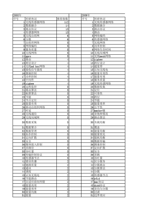

Supporting Brocade 5600 vRouter, VNF Platform, and DistributedServices PlatformSOFTWARE LICENSING GUIDE53-1004757-01© 2016, Brocade Communications Systems, Inc. All Rights Reserved.Brocade, the B-wing symbol, and MyBrocade are registered trademarks of Brocade Communications Systems, Inc., in the United States and in other countries. Other brands, product names, or service names mentioned of Brocade Communications Systems, Inc. are listed at /en/legal/ brocade-Legal-intellectual-property/brocade-legal-trademarks.html. Other marks may belong to third parties.Notice: This document is for informational purposes only and does not set forth any warranty, expressed or implied, concerning any equipment, equipment feature, or service offered or to be offered by Brocade. Brocade reserves the right to make changes to this document at any time, without notice, and assumes no responsibility for its use. This informational document describes features that may not be currently available. Contact a Brocade sales office for information on feature and product availability. Export of technical data contained in this document may require an export license from the United States government.The authors and Brocade Communications Systems, Inc. assume no liability or responsibility to any person or entity with respect to the accuracy of this document or any loss, cost, liability, or damages arising from the information contained herein or the computer programs that accompany it.The product described by this document may contain open source software covered by the GNU General Public License or other open source license agreements. T o find out which open source software is included in Brocade products, view the licensing terms applicable to the open source software, and obtain a copy of the programming source code, please visit /support/oscd.Contents Preface (5)Document conventions (5)Notes, cautions, and warnings (5)T ext formatting conventions (5)Command syntax conventions (6)Brocade resources (6)Document feedback (6)Contacting Brocade T echnical Support (7)Brocade customers (7)Brocade OEM customers (7)About This Guide (9)Licensing (11)Licensing overview (11)Obtaining a license (11)License Management Tasks (13)License management overview (13)Adding an evaluation license (13)Deleting an evaluation license (14)Configuring the license expiration-warning period (14)Viewing license information (15)Evaluation License Commands (17)add trial online (17)delete trial online (19)license expiration-warning period (20)show license installed (21)Syslog Messages (23)Preface•Document conventions (5)•Brocade resources (6)•Document feedback (6)•Contacting Brocade T echnical Support (7)Document conventionsThe document conventions describe text formatting conventions, command syntax conventions, and important notice formats used in Brocade technical documentation.Notes, cautions, and warningsNotes, cautions, and warning statements may be used in this document. They are listed in the order of increasing severity of potential hazards.NOTEA Note provides a tip, guidance, or advice, emphasizes important information, or provides a reference to related information.ATTENTIONAn Attention statement indicates a stronger note, for example, to alert you when traffic might be interrupted or the device might reboot.CAUTIONA Caution statement alerts you to situations that can be potentially hazardous to you or cause damage to hardware,firmware, software, or data.DANGERA Danger statement indicates conditions or situations that can be potentially lethal or extremely hazardous to you. Safetylabels are also attached directly to products to warn of these conditions or situations.Text formatting conventionsT ext formatting conventions such as boldface, italic, or Courier font may be used to highlight specific words or phrases.Format Descriptionbold text Identifies command names.Identifies keywords and operands.Identifies the names of GUI elements.Identifies text to enter in the GUI.italic text Identifies emphasis.Identifies variables.Identifies document titles.Courier font Identifies CLI output.Identifies command syntax examples.Brocade resourcesCommand syntax conventionsBold and italic text identify command syntax components. Delimiters and operators define groupings of parameters and their logical relationships.Convention Descriptionbold text Identifies command names, keywords, and command options.italic text Identifies a variable.value In Fibre Channel products, a fixed value provided as input to a command option is printed in plain text, forexample, --show WWN.[ ]Syntax components displayed within square brackets are optional.Default responses to system prompts are enclosed in square brackets.{ x | y | z } A choice of required parameters is enclosed in curly brackets separated by vertical bars. You must selectone of the options.In Fibre Channel products, square brackets may be used instead for this purpose.x | y A vertical bar separates mutually exclusive elements.< >Nonprinting characters, for example, passwords, are enclosed in angle brackets....Repeat the previous element, for example, member[member...].\Indicates a “soft” line break in command examples. If a backslash separates two lines of a commandinput, enter the entire command at the prompt without the backslash.Brocade resourcesVisit the Brocade website to locate related documentation for your product and additional Brocade resources.White papers, data sheets, and the most recent versions of Brocade software and hardware manuals are available at . Product documentation for all supported releases is available to registered users at MyBrocade.Click the Support tab and select Document Library to access documentation on MyBrocade or You can locate documentation by product or by operating system.Release notes are bundled with software downloads on MyBrocade. Links to software downloads are available on the MyBrocade landing page and in the Document Library.Document feedbackQuality is our first concern at Brocade, and we have made every effort to ensure the accuracy and completeness of this document. However, if you find an error or an omission, or you think that a topic needs further development, we want to hear from you. You can provide feedback in two ways:•Through the online feedback form in the HTML documents posted on •By sending your feedback to *************************Provide the publication title, part number, and as much detail as possible, including the topic heading and page number if applicable, as well as your suggestions for improvement.Contacting Brocade T echnical Support Contacting Brocade Technical SupportAs a Brocade customer, you can contact Brocade T echnical Support 24x7 online, by telephone, or by e-mail. Brocade OEM customers should contact their OEM/solution provider.Brocade customersFor product support information and the latest information on contacting the T echnical Assistance Center, go to and select Support.If you have purchased Brocade product support directly from Brocade, use one of the following methods to contact the BrocadeT echnical Assistance Center 24x7.Brocade OEM customersIf you have purchased Brocade product support from a Brocade OEM/solution provider, contact your OEM/solution provider for all of your product support needs.•OEM/solution providers are trained and certified by Brocade to support Brocade® products.•Brocade provides backline support for issues that cannot be resolved by the OEM/solution provider.•Brocade Supplemental Support augments your existing OEM support contract, providing direct access to Brocade expertise.For more information, contact Brocade or your OEM.•For questions regarding service levels and response times, contact your OEM/solution provider.About This GuideThis guide describes license and entitlement management for Brocade products that run on the Brocade Vyatta Network OS (referred to as a virtual router, vRouter, or router in the guide).Licensing•Licensing overview (11)•Obtaining a license (11)Licensing overviewAn evaluation license is available for the Brocade 5600 vRouter.The evaluation license is a nonproduction license that enables the maximum performance of the Brocade vRouter for a trial period of 60 days from the day of download.The following table describes license terminology for the Brocade vRouter.TABLE 1 License terminologyObtaining a licenseT o order and obtain a 60-day evaluation license, click FREE TRIAL at /en/products-services/software-networking/network-functions-virtualization/5600-vrouter.html.NOTEFor important installation information depending on your deployment, see the Brocade Vyatta Network OS vRouterDeployment Options Configuration Guide document. For instructions on verifying the connectivity needed to install yourlicense, see the "Verifying connectivity" section in the installation guide for your environment.Obtaining a licenseT o install a license on your Brocade vRouter, complete the following steps.1.NOTEYou should receive an entitlement e-mail from Brocade within one hour after placing your order. Sometimesentitlement e-mails are routed to junk or spam e-mail folders. If you do not receive your entitlement e-mail within onehour, check your junk and spam e-mail folders to determine if it was routed there.Download the Brocade vRouter software and read your entitlement e-mail.After installing the Brocade vRouter software and before adding an evaluation license, the Brocade vRouter displays a license warning message on bootup.Welcome to vRouterVersion: 4.0.0.R1Description: Brocade vRouter 5600 4.0.0 R1Copyright: 2015 Brocade Communications Systems, Inc.Last login: Wed Oct 21 17:22:59 2015 from 10.72.16.14WARNING: A valid vRouter 5600 license was not detected on this device.The license may not be configured or may be expired.vRouter 5600 features have been disabled.Please install a valid license within 24 hours of vRouter creation.2.Refer to the Order Details section of your entitlement e-mail for details about the activation code for your evaluation license.3.NOTEFor the automatic generation of a license key, the Brocade vRouter must be online and have public connectivity tocommunicate with the Brocade licensing portal.NOTEYou must enter your activation code to retrieve your license key after you install the Brocade vRouter software. Theactivation code can be used at any time during your evaluation period. However, the trial software runs for only 24hours after download without the activation code being entered into the system.Install and enter your activation code. For detailed information on how to add a license to your Brocade vRouter and verify that it is installed correctly, refer to Adding an evaluation license on page 13.Your 60-day evaluation license includes free support. If you have questions or need help with your evaluation license for the Brocade vRouter, contact *******************.License Management Tasks•License management overview (13)•Adding an evaluation license (13)•Deleting an evaluation license (14)•Configuring the license expiration-warning period (14)•Viewing license information (15)License management overviewA Brocade vRouter evaluation license is managed through an internet connection to a licensing portal and by using the command line interface (CLI) on the vRouter.NOTEA license must be added within the 24-hour period after installing the Brocade vRouter. When the license is not added withinthe 24-hour period, the Brocade vRouter ceases to function. The Brocade vRouter must be re-installed and the license added within the 24-hour period after re-installing the Brocade vRouter. You can add your original evaluation license to the Brocade vRouter after re-installation; you do not need to obtain a new evaluation license.Adding an evaluation licenseFor details about your Brocade vRouter license key (activation code), refer to the entitlement certificate e-mail that you receive after your Brocade vRouter license order is confirmed.For a Brocade vRouter that is connected to the internet, it is assumed that the following tasks have been completed:•Routes for internet access are set up. For further information, refer to Brocade Vyatta Network OS Basic Routing Configuration Guide.•DNS is set up. For further information, refer to Brocade Vyatta Network OS Basic System Configuration Guide and Brocade Vyatta Network OS Services Configuration Guide•Interfaces are set up. For further information, refer to Brocade Vyatta Network OS LAN Interfaces Configuration Guide.•The system host name is configured. For further information, refer to Brocade Vyatta Network OS Basic System Configuration Guide.T o add an evaluation license to a Brocade vRouter that is connected to the licensing portal, perform the following steps.1.Log on to the Brocade vRouter in operational mode.2.Add a license to the Brocade vRouter by specifying the license key.The following example shows how to add an evaluation license with a license key of ABCD-EFGH-IJKL-1234.vyatta@vyatta:~$ add trial online ABCD-EFGH-IJKL-1234License request successful.[ ok ] Restarting vyatta-routing (via systemctl): vyatta-routing.service.Deleting an evaluation license3.Enter the show license installed command to confirm that the license is added to the system.The following example shows that an evaluation license with a license key of ABCD-EFGH-IJKL-1234 is installed on the system.vyatta@vyatta:~$ show license installedDevice ID: 331cb-f91ec-b2440-7fdc0-03461-4a282-089b1-d7884Auto-Update: 1 daysExpiration Warning: 30 daysLicense: 60 DAY EVALUATION LICENSE SWActivation ID: ABCD-EFGH-IJKL-1234Feature: EvaluationIssuer: MANUFACTURER 001Start Date: 20-Oct-2015Expiration: 21-Dec-2015Deleting an evaluation licenseT o delete an evaluation license from the Brocade vRouter that is connected to the licensing portal, perform the following steps.1.Log on to the Brocade vRouter in operational mode.2.Delete the license from the system by specifying the license key.The following example shows how to delete an evaluation license with a license key of ABCD-EFGH-IJKL-1234 from the Brocade vRouter.vyatta@vyatta:~$ delete trial online ABCD-EFGH-IJKL-12343.Enter the show license installed command to confirm that the license is deleted from the system. Configuring the license expiration-warning periodBy default, license-expiration warning messages are displayed during the 30-day period before the license-expiration date on the Brocade vRouter. T o change the license expiration-warning period, perform the following steps.1.Log on to the Brocade vRouter in configuration mode.2.Enter the set license expiration-warning period command to configure the license expiration-warning period.The following example shows how to set the warning period to 40 days.vyatta@vyatta# set license expiration-warning period 40mit the change.vyatta@vyatta# commitThe license expiration-warning period is now set to 40 days on the Brocade vRouter.4.Confirm the license expiration-warning period by issuing the show license expiration-warning period command.vyatta@vyatta# show license expiration-warning periodlicense {expiration-warning {period 40}}Viewing license information Viewing license informationUse the show license installed command to view installed-license information on the Brocade vRouter.1.Log on to the Brocade vRouter in operational mode.2.Enter the show license installed command to view information about licenses that are installed on the system.The following example shows how to view that a valid evaluation license is installed on the system.vyatta@vyatta:~$ show license installedDevice ID: 331cb-f91ec-b2440-7fdc0-03461-4a282-089b1-d7884Auto-Update: 1 daysExpiration Warning: 30 daysLicense: 60 DAY EVALUATION LICENSE SWActivation ID: A047-B811-858F-DC58Feature: EvaluationIssuer: MANUFACTURER 001Start Date: 20-Oct-2015Expiration: 21-Dec-2015For examples of information that is displayed by the show license installed command at different stages of the license life cycle, refer to show license installed on page 21.Evaluation License Commands•add trial online (17)•delete trial online (19)•license expiration-warning period (20)•show license installed (21)add trial onlineAdds an evaluation license to an online system.Syntaxadd trial online license-keyParameterslicense-keyLicense key (activation code) that is used to activate the evaluation license. The format of the license-key is xxxx-xxxx-xxxx-xxxx, where x is an alphabetic or a numeric character. The license-key must include the "-" characters and is notcase-sensitive.ModesOperational modeUsage GuidelinesThe Brocade vRouter must have an internet connection to the licensing portal. For a connected system, it is assumed that the following prerequisite tasks have been completed:•Routes for internet access are set up. For further information, refer to Brocade Vyatta Network OS Basic Routing Configuration Guide.•DNS is set up. For further information, refer to Brocade Vyatta Network OS Services Configuration Guide•Interfaces are set up. For further information, refer to Brocade Vyatta Network OS LAN Interfaces Configuration Guide.•The system host name is configured. For further information, refer to Brocade Vyatta Network OS Basic System Configuration Guide.Before entering this command, it is also recommended that you:•Set the date and time zone: the license-enforcement process may interpret a change to the date or time zone that is made after a license is added to the system as license tampering and disable system functionality.•Set the host name and domain name: after the host name and domain name are set, it is easy to identify the system on the licensing portal because the fully qualified name, that is, hostname.domain is displayed next to the device ID onthe portal.add trial onlineExamplesThe following example shows how to add an evaluation license (with the license key of ABCD-EFGH-IJKL-1234) to the Brocade vRouter that is connected to the licensing portal.vyatta@vyatta:~$ add trial online ABCD-EFGH-IJKL-1234delete trial online delete trial onlineDeletes an evaluation license from an online system.Syntaxdelete trial online license-keyParameterslicense-keyLicense key (activation code) to be deleted. The format of the license-key is xxxx-xxxx-xxxx-xxxx, where x is analphabetic or a numeric character. The license-key must include the "-" characters and is not case-sensitive.ModesOperational modeUsage GuidelinesThe Brocade vRouter must have an internet connection to the licensing portal. For a connected system, it is assumed that the following prerequisite tasks have been completed:•Routes for internet access are set up. For further information, refer to Brocade Vyatta Network OS Basic Routing Configuration Guide.•DNS is set up. For further information, refer to Brocade Vyatta Network OS Services Configuration Guide•Interfaces are set up. For further information, refer to Brocade Vyatta Network OS LAN Interfaces Configuration Guide.•The system host name is configured. For further information, refer to Brocade Vyatta Network OS Basic System Configuration Guide.ExamplesThe following example shows how to delete the ABCD-EFGH-IJKL-1234 evaluation license from the Brocade vRouter that is connected to the licensing portal.vyatta@vyatta:~$ delete trial online ABCD-EFGH-IJKL-1234license expiration-warning periodlicense expiration-warning periodSpecifies the license expiration-warning period.Syntaxset license expiration-warning period daysdelete license expiration-warning period daysCommand DefaultThe display of messages is enabled.ParametersdaysNumber of days for the license expiration-warning period, that is, the period during which the Brocade vRouterdisplays upcoming license expiration-warning messages. The number of days ranges from 0 through 120. The defaultis 30. Specifying 0 disables the display of upcoming license expiration-warning messages on the system.ModesConfiguration modeConfiguration Statementlicense {expiration-warning {period days}}Usage GuidelinesBy default, the Brocade vRouter displays license expiration-warning messages for the 30-day period before the license-expiration date. Use the set form of this command to configure an alternate license expiration-warning period.Use the delete form of this command to restore the default license expiration-warning period of 30 days.show license installed show license installedDisplays information about installed licenses.Syntaxshow license installedModesOperational modeUsage GuidelinesThis command displays information about licenses that are installed on the Brocade vRouter. It also checks and displays, where applicable, license-related warning messages.Command OutputThis command displays the following information.ExamplesFor a new system when a license is not yet installed, this command shows the following information.vyatta@vyatta:~$ show license installedDevice ID: 331cb-f91ec-b2440-7fdc0-03461-4a282-089b1-d7884Auto-Update: 1 daysExpiration Warning: 30 daysWARNING: A valid vRouter 5600 license was not detected on this device.The license may not be configured or may be expired.vRouter 5600 features have been disabled.Please install a valid license within 24 hours of vRouter creation.show license installedWhen a valid evaluation license is installed, this command shows the following information.vyatta@vyatta:~$ show license installedDevice ID: 331cb-f91ec-b2440-7fdc0-03461-4a282-089b1-d7884Auto-Update: 1 daysExpiration Warning: 30 daysLicense: 60 DAY EVALUATION LICENSE SWActivation ID: A047-B811-858F-DC58Feature: EvaluationIssuer: MANUFACTURER 001Start Date: 20-Oct-2015Expiration: 21-Dec-2015In the following example, the license expiration-warning period is configured as 30 days. During the 30-day period before the license-expiration date of December 21, 2015 ( 21-Dec-2015) this command shows the following information.vyatta@vyatta:~$ show license installedDevice ID: 331cb-f91ec-b2440-7fdc0-03461-4a282-089b1-d7884Auto-Update: 1 daysExpiration Warning: 30 daysLicense: 60 DAY EVALUATION LICENSE SWActivation ID: A047-B811-858F-DC58Feature: EvaluationIssuer: MANUFACTURER 001Start Date: 20-Oct-2015Expiration: 21-Dec-2015WARNING: The license for A047-B811-858F-DC58 will expire on 21-Dec-2015.Syslog MessagesMessage A valid vRouter 5600 license was not detected on this device.Explanation Indicates that a valid license is not detected on the system. If a license exists, it may not be configured or it may have expired. For further information about license management, refer to the License Management Tasks section. Message Level WarningMessage The license for ABCD-EFGH-IJKL-1234 will expire on 30-Oct-2015.Explanation Indicates that the current date on the system is within the warning period before the license expiration date. Message Level WarningMessage The license for <ABCD-EFGH-IJKL-1234 expired on 30-Oct-2015.Explanation Indicates that the license has expired but the current date on the system is within the grace period allowed for license renewal. Licensed features on the system continue to function but changes are not permitted.Message Level Alert。

Card Management System Integration Guide Oracle Banking OriginationRelease 14.5.3.0.0Part Number F51366-01November 2021Card Management System Integration GuideOracle Financial Services Software LimitedOracle ParkOff Western Express HighwayGoregaon (East)Mumbai, Maharashtra 400 063IndiaWorldwide Inquiries:Phone: +91 22 6718 3000Fax: +91 22 6718 3001https:///industries/financial-services/index.htmlCopyright © 2021, Oracle and/or its affiliates. All rights reserved.Oracle and Java are registered trademarks of Oracle and/or its affiliates. Other names may be trademarks of their respective owners.U.S. GOVERNMENT END USERS: Oracle programs, including any operating system, integrated software, any programs installed on the hardware, and/or documentation, delivered to U.S. Government end users are “commercial computer software” pursuant to the applicable Federal Acquisition Regulation and agency-specific supplemental regulations. As such, use, duplication, disclosure, modification, and adaptation of the programs, including any operating system, integrated software, any programs installed on the hardware, and/or documentation, shall be subject to license terms and license restrictions applicable to the programs. No other rights are granted to the U.S. Government.This software or hardware is developed for general use in a variety of information management applications. It is not developed or intended for use in any inherently dangerous applications, including applications that may create a risk of personal injury. If you use this software or hardware in dangerous applications, then you shall be responsible to take all appropriate failsafe, backup, redundancy, and other measures to ensure its safe use. Oracle Corporation and its affiliates disclaim any liability for any damages caused by use of this software or hardware in dangerous applications.This software and related documentation are provided under a license agreement containing restrictions on use and disclosure and are protected by intellectual property laws. Except as expressly permitted in your license agreement or allowed by law, you may not use, copy, reproduce, translate, broadcast, modify, license, transmit, distribute, exhibit, perform, publish or display any part, in any form, or by any means. Reverse engineering, disassembly, or decompilation of this software, unless required by law for interoperability, is prohibited. The information contained herein is subject to change without notice and is not warranted to be error-free. If you find any errors, please report them to us in writing.This software or hardware and documentation may provide access to or information on content, products and services from third parties. Oracle Corporation and its affiliates are not responsible for and expressly disclaim all warranties of any kind with respect to third-party content, products, and services. Oracle Corporation and its affiliates will not be responsible for any loss, costs, or damages incurred due to your access to or use of third-party content, products, or services.Contents 1About this manual (1)1.1Purpose (1)1.2Audience (1)1.3List of Topics (1)2Integration Guide (2)2.1Introduction (2)2.2Prerequisite (2)2.3Maintenance for Oracle Banking Origination (2)2.4API for Oracle Banking Origination (6)1 About this manual1.1 PurposeThis guide is to help with Integration of Oracle Banking Origination Product with Card ManagementSystem acting as the backend Product Processor.1.2 AudienceThis guide is primarily intended for the following user/user roles:Table 1: AudienceRole FunctionImplementation and ITImplementation and maintenance of the softwareStaff1.3 List of TopicsTable 2: TopicsTopics DescriptionIntegration Guide This topic helps you to integrate Oracle Banking Origination product withCard Management System.2 Integration Guide2.1 IntroductionYou can integrate Oracle Banking Origination with Card Management System acting as the backend Product Processor through Oracle Banking Routing Hub. This document briefs you about the specific steps needed for integration of these two products and specific maintenances.2.2 PrerequisiteCard Management System should be available, with support to list of consumer services are detailed in Section 2.4.2.3 Maintenance for Oracle Banking Origination1. Maintain Oracle Banking Routing Hub routing configuration in common core for CC_HOST.2. From Home screen, click Core Maintenance. Under Core Maintenance, click Routing Hub.3. Under Routing Hub, click Service Consumers.→The Service Consumers screen is displayed.Figure 1: Service Consumers4. Click Import and upload the RPM_ORIGINATION_Consumer.json file provided in the release andclick Extract.Figure 2: Success5. Select CC_HOST and click Import.Figure 3: ConfirmationFigure 4: RPM Origination6. Click RPM_ORIGINATION.7. Under RPM_ORIGINATION, click CC_HOST.Figure 5: RPM OriginationFigure 6: RPM Origination8. Click Edit.9. Change the host and port as per the Oracle FLEXCUBE Universal Banking installation and save it.Figure 7: Edit ImplementationThe below consumer services will be imported.Figure 8: Consumer ServicesRefer Routing Hub Configuration User Guide for more details.2.4 API for Oracle Banking Origination1. Get_Host_Product_Details_By_CodeParent Node: HostProductListField Name Field Description Type LengthproductCode Host Product Code String 4String 50 productDescription Host ProductDescriptionproductType String 12. Get_Host_Product_Details_ListParent Node: dataField Name Field Description Type LengthproductCode Host Product Code String 4String 50 productDescription Host ProductDescriptionproductType String 1Child Node: componentsParent Node: dataField Name Field Description Type LengthcomponentName Host Product Code String 4String 50 componentDescription Host ProductDescriptioncomponentType Component Type String 1hostComponentType Host Component Type String 1mainComponent Main Component String 1String 50 componentReportingType Reporting type Interest/ChargeratetoUse Rate to Use String 50Child Node: productUdesParent Node: componentsField Name Field Description Type Length productCode Host Product Code String 4productDescription Host ProductString 50DescriptionproductType String 13. Save_Credit_Card_DS_DetailsField Name Field Description Type LengthString 35 processRefNo Process ReferenceNumberapplicationNo Application Number String 16 Kindly refer swagger documentation for allDSDetails for credit card application.Card Management System Integration Guide Copyright @ 2021 8 All Rights Reserved As part of response, credit card number is expected. Field NameField Description Type Length creditcardnumberCredit Card Number Long 164. Update_Credit_Card_NumberUse this API in case of unsynchronized call. Field NameField Description Type Length processRefNoProcess Reference Number String 35 cardNumber Credit Card Number Integer 16。

标准NMEA协议协议名称:标准NMEA协议一、引言本协议旨在定义标准NMEA(National Marine Electronics Association)协议的格式和规范,以便在航海和导航领域中实现数据的交互和共享。
该协议适用于各种航海设备和导航系统,包括但不限于GPS接收器、导航仪器、自动驾驶系统等。
二、协议格式标准NMEA协议采用ASCII码字符作为数据传输的基本单位,每条数据以"$"符号开头,以"\r\n"作为结束符。
数据由多个字段组成,字段之间以逗号分隔。
三、协议字段1. 语句类型字段(Sentence Type Field):标识数据的类型,由两个字母组成,如GP、GL、GA等,不同的语句类型表示不同的数据内容。
2. 数据字段(Data Field):包含具体的数据信息,根据语句类型的不同,数据字段的数量和格式也不同。
四、协议语句类型1. GGA(Global Positioning System Fix Data):提供有关GPS定位质量的信息,包括经纬度、海拔高度、卫星数量等。
2. RMC(Recommended Minimum Navigation Information):提供推荐的最小导航信息,包括位置、速度、航向等。
3. GSA(GPS DOP and Active Satellites):提供GPS接收器的工作状态和卫星信息,包括DOP(Dilution of Precision)值、使用的卫星编号等。
4. GSV(GPS Satellites in View):提供当前可见卫星的信息,包括卫星编号、仰角、方位角、信号强度等。
5. VTG(Course Over Ground and Ground Speed):提供地面速度和航向信息。
6. ZDA(Time and Date):提供UTC时间和日期。
五、协议数据字段1. GGA数据字段:- UTC时间:hhmmss.sss- 纬度:ddmm.mmmm- 纬度半球:N(北纬)/S(南纬)- 经度:dddmm.mmmm- 经度半球:E(东经)/W(西经)- 定位质量指示:0(无效定位)/1(GPS定位解)/2(差分GPS定位解)/6(估算定位)- 使用卫星数量:00-12- HDOP(水平精度因子):0.5-99.9- 海拔高度:-9999.9-99999.9- 大地水准面分离:-9999.9-99999.9- 差分GPS数据期限:以秒为单位,-9999.9-99999.9- 差分参考基站ID:0000-10232. RMC数据字段:- UTC时间:hhmmss.sss- 定位状态:A(有效定位)/V(无效定位)- 纬度:ddmm.mmmm- 纬度半球:N(北纬)/S(南纬)- 经度:dddmm.mmmm- 经度半球:E(东经)/W(西经)- 地面速度:0-999.9节- 地面航向:000.0-359.9度- UTC日期:ddmmyy- 磁偏角:-180.0-180.0度- 磁偏角方向:E(东)/W(西)- 模式指示:A(自主定位)/D(差分定位)/E(估算定位)/N(数据无效)3. GSA数据字段:- 模式选择:M(手动)/A(自动)- 模式:1(没有可用卫星)/2(2D定位)/3(3D定位)- 使用的卫星编号:01-32- PDOP(位置精度因子):0.5-99.9- HDOP(水平精度因子):0.5-99.9- VDOP(垂直精度因子):0.5-99.94. GSV数据字段:- 可见卫星数量:01-12- 当前语句号:1-9- 总语句数:1-9- 卫星编号:01-32- 仰角:00-90度- 方位角:000-359度- 信号强度:00-995. VTG数据字段:- 地面航向:000.0-359.9度- 地面速度:0-999.9节- 地面速度单位:N(节)6. ZDA数据字段:- UTC时间:hhmmss.sss- 日:01-31- 月:01-12- 年:0000-9999- 本地时区小时偏移量:-13-13 - 本地时区分钟偏移量:00-59六、协议示例$GPGGA,123519,4807.038,N,01131.000,E,1,08,0.9,545.4,M,46.9,M,,*47$GPRMC,123519,A,4807.038,N,01131.000,E,022.4,084.4,230394,003.1,W*6A$GPGSA,A,3,04,05,,09,12,,,24,,,,,2.5,1.3,2.1*39$GPGSV,3,1,11,20,74,148,26,22,54,231,17,24,40,069,20,25,38,230,20*79$GPGSV,3,2,11,27,34,071,15,30,23,292,,40,13,083,17,42,28,221,14*78$GPGSV,3,3,11,09,09,014,,14,07,344,,18,05,175,*74$GPVTG,054.7,T,034.4,M,005.5,N,010.2,K*48$GPZDA,201530.00,04,07,2002,00,00*60七、结论本标准NMEA协议提供了航海和导航领域中数据交互和共享的规范,定义了不同语句类型和数据字段的格式和含义。

camunda tasklistener delegate expression用法-回复首先,让我们来介绍一下Camunda和TaskListener的概念。
Camunda是一种流程引擎,它允许用户定义和执行业务流程。
它提供了一个开发框架,可用于建模、执行和监控业务流程。
Camunda流程引擎具有高度可扩展性和灵活性,因此广泛用于各种企业应用中。
TaskListener是Camunda流程引擎的一种功能,允许用户在任务的生命周期中插入自定义逻辑。
通过在流程中添加TaskListener,可以在任务分配、开始、完成等事件发生时触发自定义的操作。
TaskListener可以有多种触发方式,其中一种方式就是使用Delegate Expression。
Delegate Expression是一种通用的表达式语言,用于动态地指定一个Java类或Bean实例,以执行在表达式中定义的任务。
在Camunda中,可以使用Delegate Expression来指定一个实现了特定接口的Java类来处理任务监听器。
现在,让我们一步一步地来回答关于Camunda TaskListener Delegate Expression的用法。
第一步:定义TaskListener接口实现类首先,我们需要创建一个Java类来实现TaskListener接口。
这个类需要实现TaskListener接口中定义的方法,例如notify、notifyBefore和notifyAfter等。
这些方法将在任务相关事件发生时被调用,并执行自定义逻辑。
第二步:配置Delegate Expression接下来,我们需要在BPMN文件中配置TaskListener,并使用Delegate Expression来指定实现了TaskListener接口的Java类。
在BPMN中,可以使用表达式语言来指定Delegate Expression,例如{myTaskListener}。


基于Web工作流管理系统的解决方案
杨斌;郝克刚
【期刊名称】《西北大学学报:自然科学版》
【年(卷),期】1999(029)006
【摘要】提出了一种基于Web工作流管理系统的解决方案,该系统采用3层体系结构,实现上将CORBA与Java相结合,利用分布式对象计算技术CORBA的代理机制来实现客户机与服务器的分离及通信。
【总页数】4页(P491-494)
【作者】杨斌;郝克刚
【作者单位】西北大学计算机科学系;西北大学计算机科学系
【正文语种】中文
【中图分类】TP317
【相关文献】
1.基于Web的工艺生产工作流管理系统的研究与实现 [J], 杨雁
2.基于Web Service的工作流管理系统的研究与实现 [J], 王晓萍;柯敏毅
3.基于Web的工作流管理系统的设计与实现 [J], 张杰
4.基于WEB的工作流管理系统研究与应用 [J], 王彦超
5.基于Web工作流管理系统的设计与实现 [J], 罗晓玲
因版权原因,仅展示原文概要,查看原文内容请购买。