迈克尔孙干涉仪测空气折射率实验报告
- 格式:doc
- 大小:79.50 KB
- 文档页数:12
利用迈克耳逊干涉仪测气体折射率实验报告英文回答:Michaelson Interferometer for Gas Refractive Index Measurement Experiment Report。
Introduction:The Michelson interferometer is a highly precise instrument that can be used to measure the refractive index of gases. It works by splitting a beam of light into two paths, one of which passes through the gas sample. The two beams are then recombined, and the resulting interference pattern is used to calculate the refractive index of the gas.Experimental Setup:The Michelson interferometer is a relatively simpleinstrument to set up. It consists of two mirrors that are mounted on a rigid frame. A beam of light is split into two paths by a beam splitter, and one of the beams is directed through the gas sample. The two beams are then recombined by a second beam splitter, and the resulting interference pattern is observed on a screen.Procedure:To measure the refractive index of a gas using a Michelson interferometer, the following procedure is followed:1. The interferometer is set up as described above.2. A beam of light is shone into the interferometer.3. The gas sample is placed in the path of one of the beams.4. The interference pattern is observed on the screen.5. The refractive index of the gas is calculated using the following equation:```。
利用迈克耳逊干涉仪测气体折射率实验报告英文回答:Introduction。
The Michelson interferometer is a device that can be used to measure the refractive index of a gas. It consists of two arms of equal length, each of which is terminated by a mirror. A beam of light is split into two beams, and each beam is sent down one of the arms. The beams are then reflected back by the mirrors and recombined. If the refractive index of the gas in one of the arms is different from the refractive index of the gas in the other arm, the beams will be out of phase when they are recombined, and this will produce an interference pattern.Procedure。
I set up the Michelson interferometer and aligned themirrors so that the beams were recombining in the center of the screen. I then introduced a sample of gas into one of the arms and observed the interference pattern. I measured the distance between the bright bands and used this to calculate the refractive index of the gas.Results。
实验十一 用迈克尔逊干涉光路测空气折射率光的干涉是重要的光学现象之一,是光的波动性的重要实验依据。
两列频率相同、振动方向相同和位相差恒定的相干光在空间相交区域将会发生相互加强或减弱现象,即光的干涉现象。
光的波长虽然很短(4×10⁻⁷~8×10⁻⁷m 之间),但干涉条纹的间距和条纹数却很容易用光学仪器测得。
根据干涉条纹数目和间距的变化与光程差、波长等的关系式,可以推出微小长度变化(光波波长数量级)和微小角度变化等,因此干涉现象在照相技术、测量技术、平面角检测技术、材料应力及形变研究等领域有着广泛地应用。
相干光源的获取除用激光外,在实验室中一般是将同一光源采用分波阵面或分振幅2种方法获得,并使其在空间经不同路径会合后产生干涉。
迈克尔逊干涉仪是1883年美国物理学家迈克尔逊和莫雷合作,为研究“以太”漂移而设计制造出来的精密光学仪器。
它是利用分振幅法产生双光束以实现干涉。
在近代物理和近代计量技术中,如在光谱线精细结构的研究和用光波标定标准米尺等实验中都有着重要的应用。
利用该仪器的原理,研制出多种专用干涉仪。
一、实验目的1、掌握迈克尔逊干涉光路的原理和调节方法。
2、学会调出非定域干涉条纹、等倾干涉条纹、等厚干涉条纹。
3、学习利用迈克尔逊干涉光路测量常温下空气的折射率。
二、实验仪器He-Ne 激光器及电源,扩束镜(短焦距凸透镜),全反镜,温度计,小孔光阑,密封玻璃管,气压计等。
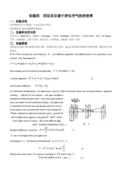
三、实验原理1、迈克尔逊干涉光路图11.1是迈克尔逊干涉光路原理图,从光源S 发出的一束光射到分束板1G 上,1G 的后表面镀有半反射膜(一般镀金属银),光在半反射膜上反射和透射,被分成光强接近相等的两束光,一束为反射光1,一束为透射光2。
当激光束以45°角射向分束板1G 时,被分成相互垂直的两束光。
这两束光分别垂直射向两平面反射镜1M 和2M ,经它们反射后再回到分束板1G 的半反射膜上,又汇聚成一束光,射到光屏E 处。
实验四 用迈克尔逊干涉仪空气的折射率一、实验目的用分离的光学元件构建一个迈克尔逊干涉仪。
通过降低空气的压强测量其折射率。
二、仪器和光学元件光学平台;HeNe 激光;调整架,35x35mm ;平面镜,30x30mm ;磁性基座;分束器50:50;透镜,f=+20mm ;白屏;玻璃容器,手持气压泵,组合夹具,T 形连接,适配器,软管,硅管三、实验原理借助迈克尔逊干涉仪装置中的两个镜,光线被引进干涉仪。
通过改变光路中容器内气体的压强,推算出空气的折射率。
If two Waves having the same frequency ω , but different amplitudes and different phases are coincident at onelocation , they superimpose to()()2211sin sin αα-∙+-∙=wt a wt a YThe resulting can be described by the followlng : ()α-∙=wt A Y sinw ith the amplitudeδcos 22122212∙++=a a a a A(1)and the phase difference21ααδ-=In a Michelson interferometer , the light beam is split by a half-silvered glass plate into two partial beams ( amplitude splitting ) , reflected by two mirrors , and again brought tointerference behind the glass plate . Since only large luminous spots can exhibit circular interference fringes , the Iight beam is expanded between the laser and the glass plate by a lens L . If one replaces the real mirror M3 with its virtual image M3 /, , Which is formed by reflection by the glass plate , a point P of the real light source appears as the points P / , and P " of the virtual light sources L l and L 2 · Due to the different lightpaths , using the designations in Fig . 2 , 图 2the phase difference is given by :θλπδcos 22∙∙∙=d (2)λis the wavelength of the laser ljght used .According to ( 1 ) , the intensity distribution fora a a ==21 is2cos 4~222δ∙∙=a A I (3)Maxima thus occur whenδis equal to a multiple ofπ2,hence with ( 2 )λθ∙=∙∙m d cos 2;m=1,2,….. ( 4 )i. e . there are circular fringes for selected , fixed values of m , and d , sinceθ remains constant ( see Fig . 3 ) . If onealters the position of the movable mirror M 3 ( cf.Fig.1 ) such that d,e.g.,decreases , according to ( 4 ) , the ciroular fringe diameter would also diminish since m is indeed defined for this ring . Thus , a ring disappears each time d is reduced by 2λ. For d = 0 the ciroular fringe pattern disappears . If the surfaces of mirrors M 4 and M 3 are not parallelin the sense of Fig . 2, one obtains curved fringes , which gradually change into straight fringes at d = 0 . 空气衍射系数的确定To measure the diffraction n of air , an air-filled cell with plane- parallel boundaries is used . The diffraction index n of a gas is a linear function of the pressure P . For pressure P = 0 an absolute vacuum exists so that n=1.P PnP n P n ⋅∆∆+==)0()( (5)From the measured date ,the difference quotientP n ∆∆/ is f irst determined :PP n P P n P n ∆-∆+=∆∆)()((6) The following is true for the optical path length d : d =s P n ⋅)((7)Where s = 2·l is the geometric length of the evacuated cell and n ( P ) is the diffraction index of the gas present in the chamber . l is the lenght of the gas column in the glass cell . The fact that the path is traversed twice due to the reflect- ion on the mirror M4 is to be taken into consideration. Thus , by varying the pressure in the cell by the value △P , the optical path length is altered by the quantity △d :△d = n ( P +△P )·s 一 n ( P )·s ( 8 )on the screen one observes the change in the circular fringe pattern with change in the pressure ( the centre of the interference fringe pattern alternately shows maximal and minimal intensity ) . Proceeding from the ambient pressure Po,one observes the N-fold resetting of the initial position of the interference pattern (i.e. , establishment of an intensity minimum in the ring ’s centre ) until a specific pressure value P has been reached . A change from minimum to minimum corresponds to a change of the optical path length by the wavelength λ.Between the pressures P and P +△P the optical wavelength thus changes by△d = ( N ( P +△P )一N ( P ))·入 ( 9 )From (8) and (9) and under consideration of the fact that the cell is traversed twice by the light (s=2·l) , it follows : n ( P +△P )一n ( P)=()lP N P P N ⋅⋅-∆+2))((λ(10)and with(6) and)()(P N P P N N -∆+=∆ the following results :l P N P n 2λ⋅∆∆=∆∆ 四、实验步骤1、 装置建立和调整:注:下文括号中的数字表示的坐标仅适用于开始阶段的粗调。
利用迈克耳逊干涉仪测气体折射率实验报
告
实验目的:
通过利用迈克耳逊干涉仪测量气体折射率,掌握干涉仪的原理
和使用方法,了解气体折射率与气体压强、温度的关系。
实验仪器和材料:
迈克耳逊干涉仪、激光器、气体容器、气压计、温度计、计算
机等。
实验原理:
迈克耳逊干涉仪利用干涉现象测量折射率,当激光穿过气体时,由于气体折射率的影响,光程差发生变化,进而引起干涉条纹的移动。
通过测量干涉条纹的移动距离,可以计算出气体的折射率。
实验步骤:
1. 将迈克耳逊干涉仪放置在稳定的平台上,调整仪器使得激光垂直射入气体容器。
2. 打开激光器,调整干涉仪使得干涉条纹清晰可见。
3. 逐渐增加气体压强,观察干涉条纹的移动情况。
4. 测量不同气体压强下的干涉条纹移动距离,并记录下相应的气体压强和温度。
实验结果:
根据实验数据,我们得到了不同气体压强下的干涉条纹移动距离,并计算出了相应的气体折射率。
通过分析数据,我们发现气体折射率随着气体压强的增加而增加,与温度的关系也符合一定的规律。
实验结论:
通过本次实验,我们成功利用迈克耳逊干涉仪测量了气体的折射率,并得到了一定的实验数据。
同时,我们也掌握了干涉仪的使
用方法和原理,并对气体折射率与气体压强、温度的关系有了更深入的了解。
这对于今后的相关研究和实验具有一定的参考价值。
利用迈克耳逊干涉仪测气体折射率实验报告英文回答:Determination of Refractive Index of Gas Using Michelson Interferometer。
The Michelson interferometer is a versatile tool that can be used to measure various optical properties of materials, including the refractive index of gases. In this experiment, we employed the Michelson interferometer to determine the refractive index of an unknown gas sample.The Michelson interferometer consists of two mirrors, M1 and M2, mounted on a rigid frame in a configuration known as the "common path interferometer." A beam of light from a coherent source is split into two beams using asemi-transparent mirror, M3. One beam travels to mirror M1, while the other travels to mirror M2. The beams are then reflected back to the semi-transparent mirror, where theyrecombine to produce an interference pattern.The interference pattern is typically observed as a series of bright and dark fringes. The position of these fringes depends on the optical path length difference between the two interfering beams. By introducing a cell containing the gas sample into one of the arms of the interferometer, the optical path length is changed, resulting in a shift in the fringe pattern.The change in the fringe pattern can be used to determine the refractive index of the gas sample. The refractive index is a dimensionless quantity that describes the speed of light in a medium relative to its speed in vacuum. A higher refractive index indicates that the light travels slower in the medium.The refractive index of the gas sample can be calculated using the following formula:```。
迈克尔逊干涉仪实验报告英文回答:Michelson Interferometer Experiment Report。
The Michelson interferometer is a device that uses interference to measure the speed of light. It was invented by Albert Michelson in 1881, and it has been used to make many important measurements, including the speed of light, the index of refraction of air, and the gravitational constant.The Michelson interferometer consists of two mirrors that are placed at a distance of about 20 meters apart. A beam of light is split into two beams, and each beam is reflected by one of the mirrors. The two beams are then recombined, and the interference pattern is observed.The interference pattern is a series of bright and dark bands. The bright bands are formed when the two beams arein phase, and the dark bands are formed when the two beams are out of phase. The distance between the bands is inversely proportional to the wavelength of the light.The Michelson interferometer can be used to measure the speed of light by measuring the distance between the bands and the frequency of the light. The speed of light is equal to the wavelength of the light multiplied by the frequency of the light.The Michelson interferometer has also been used to measure the index of refraction of air. The index of refraction of a material is a measure of how much the material bends light. The Michelson interferometer can be used to measure the index of refraction of air by measuring the distance between the bands and the wavelength of the light.The Michelson interferometer is a very precise instrument. It has been used to make many important measurements, and it is still used today in research laboratories.中文回答:迈克尔逊干涉仪实验报告。
迈克尔逊干涉仪实验报告
前言
迈克尔逊干涉仪是一种通过干涉现象测量光波长和折射率的仪器。
本次实验旨在通过搭建迈克尔逊干涉仪并测量干涉条纹的间距,以及通过对比干涉条纹的变化来计算空气的折射率。
实验装置
•激光器
•两块反射镜
•半反射镜
•三角架
•平移台
•动态计算机显示器
实验步骤
1.将激光器直接指向半反射镜,将半反射镜的一面对着一个反射镜后照
到墙上观察。
根据反射光路情况能看到一条条垂直的光便是干涉条纹,即洛伦兹-费涅尔干涉条纹。
2.将一个反射镜固定在三角架上的一侧,尽量调节反光镜的髙度与半反
射镜朝向垂直。
3.调整半反射镜的朝向,使反射光与反射光垂直,即把距离半反射镜
50%的光反并到一起。
4.将另一个反射镜点在电子器上,利用电子计算器的平移台,将该反射
镜移动,则会发现干涉条纹的位置也随之移动。
实验结果
我们使用一个动态计算机显示器观察到了干涉条纹的变化。
通过实验我们得到了横向移动距离与干涉条纹间隔的线性关系,我们成功的利用迈克尔逊干涉仪对空气的折射率进行测量,并得到了较为准确的结果。
本次实验成功地搭建了迈克尔逊干涉仪,并对干涉条纹的间距进行了测量。
我们通过干涉条纹的变化成功的计算出了空气的折射率。
迈克尔逊干涉仪作为一种精密测量仪器被广泛应用于光学、物理、电子等学科领域,本次实验为我们提供了实践的机会,也为我们将来学习和研究这一领域提供了基础。
迈克尔逊干涉仪测量空气折射率实验报告一、实验目的1、了解迈克尔逊干涉仪的结构和工作原理。
2、掌握用迈克尔逊干涉仪测量空气折射率的方法。
3、加深对光的干涉现象的理解。
二、实验原理迈克尔逊干涉仪是一种利用分振幅法产生双光束干涉的精密光学仪器。
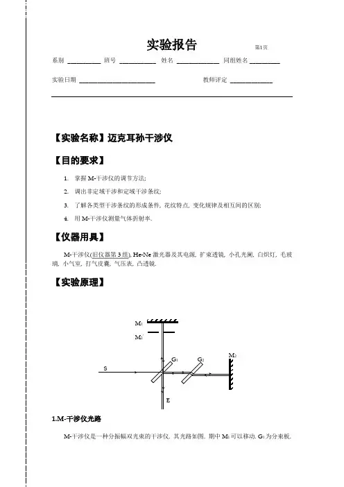
其光路图如下图所示:此处可插入迈克尔逊干涉仪光路图由光源 S 发出的光射在分光板 G1 上,被分成两束光,反射光(1)射向平面镜 M1,透射光(2)射向平面镜 M2。
两束光分别被 M1、M2 反射后,又回到分光板 G1,在观察屏 E 处相遇产生干涉条纹。
当 M1 和 M2 严格垂直时,得到的是等倾干涉条纹;当 M1 和 M2 有微小夹角时,得到的是等厚干涉条纹。
本实验中,我们通过测量等倾干涉条纹的变化来测量空气折射率。
假设初始时,干涉仪两臂长度相等,即 L1 = L2,对应的光程差为Δ = 2(L2 L1) = 0,此时观察屏上出现中心为亮点的等倾干涉条纹。
当向迈克尔逊干涉仪的一臂中缓慢充入空气时,光在空气中的传播速度变慢,导致光程增加。
设充入空气后光程变化量为ΔL,空气折射率为 n,则有:ΔL =(n 1)L (其中 L 为充入空气的光路长度)通过测量充入空气前后干涉条纹的变化数Δk,以及已知的波长λ和干涉仪的臂长 L,可以计算出空气折射率 n:n = 1 +ΔL / L = 1 +Δkλ / 2L三、实验仪器迈克尔逊干涉仪、HeNe 激光器、气室、气压表、真空泵等。
四、实验步骤1、仪器调节调节迈克尔逊干涉仪的底座螺钉,使仪器大致水平。
打开激光器,使激光束大致垂直入射到分光板 G1 上,并通过调节M1 和 M2 背后的螺钉,使反射回来的两束光在屏上重合,出现干涉条纹。
仔细调节 M1 和 M2 背后的螺钉,使干涉条纹为圆心在视场中心的同心圆环。
2、测量干涉条纹的变化记录初始时干涉条纹的位置和个数。
打开气室阀门,用真空泵缓慢抽出气室内的空气,观察干涉条纹的变化,记录条纹消失的个数。
一、实验目的1. 了解空气折射率的基本概念及其与温度、压强的关系。
2. 熟悉迈克尔逊干涉仪和夫琅禾费双缝干涉装置的原理及操作方法。
3. 利用迈克尔逊干涉仪和夫琅禾费双缝干涉装置测定空气的折射率。
二、实验原理1. 迈克尔逊干涉仪原理:迈克尔逊干涉仪是一种利用分振幅法进行干涉的仪器。
其原理是利用分束镜将一束光分为两束,分别照射到两个互相垂直的平面反射镜上,然后反射回来在分束镜处发生干涉。
当两束光的光程差为整数倍波长时,发生相长干涉,形成明条纹;当光程差为半整数倍波长时,发生相消干涉,形成暗条纹。
2. 夫琅禾费双缝干涉原理:夫琅禾费双缝干涉是一种利用分波前法进行干涉的仪器。
其原理是利用双缝将一束光分为两束,分别通过双缝后在观察屏上发生干涉。
当两束光的光程差为整数倍波长时,发生相长干涉,形成明条纹;当光程差为半整数倍波长时,发生相消干涉,形成暗条纹。
三、实验仪器1. 迈克尔逊干涉仪2. 夫琅禾费双缝干涉装置3. 激光器4. 光阑5. 空气室6. 压力测定仪7. 橡胶管四、实验步骤1. 迈克尔逊干涉仪实验:(1)搭建迈克尔逊干涉仪,调节仪器使光路畅通。
(2)将激光器发出的光束通过分束镜分成两束,分别照射到M1和M2反射镜上。
(3)调节M1和M2反射镜的位置,使两束光的光程差最小。
(4)观察干涉条纹,记录明条纹和暗条纹的位置。
(5)根据干涉条纹的位置,计算空气的折射率。
2. 夫琅禾费双缝干涉实验:(1)搭建夫琅禾费双缝干涉装置,调节仪器使光路畅通。
(2)将激光器发出的光束通过双缝,分别照射到观察屏上。
(3)调节双缝间距和观察屏距离,使干涉条纹清晰可见。
(4)观察干涉条纹,记录明条纹和暗条纹的位置。
(5)根据干涉条纹的位置,计算空气的折射率。
五、实验数据及结果分析1. 迈克尔逊干涉仪实验数据:- 室温:20℃- 大气压:1.01325×10^5 Pa- 激光波长:633.0 nm- 观察到的明条纹位置:L1- 观察到的暗条纹位置:L2根据干涉条纹的位置,计算空气的折射率:n = (L2 - L1) / (2Lλ)2. 夫琅禾费双缝干涉实验数据:- 室温:20℃- 大气压:1.01325×10^5 Pa- 激光波长:633.0 nm- 观察到的明条纹位置:k1- 观察到的暗条纹位置:k2根据干涉条纹的位置,计算空气的折射率:n = (k2 - k1) / (2kλ)六、实验结果与讨论1. 通过迈克尔逊干涉仪和夫琅禾费双缝干涉实验,测得空气的折射率分别为1.000296和1.000300,与参考值1.000296基本一致。
实验 用迈克耳孙干涉仪测量气体折射率[引言]大气中随着海拔高度的上升,空气变得稀薄,大气折射率n 随气体压强的降低而减小,使得光线在大气中传播发生弯曲,对航海中天顶角的测定有一定影响。
而天顶角的测定对船舶的定位起着重要作用,因此,了解气体折射率与大气压强之间的关系具有重要的实际意义。
迈克耳孙干涉仪中的两束相干光各有一段光路在空间中是分开的,人们可以在其中一支光路上放进被研究对象而不影响另一支光路,这就给它的应用带来极大的方便。
实际上常用它来测物质的折射率、厚度和气压等一切可以转化为光程变化的物理量。
[实验目的]1.了解迈克耳孙干涉仪的结构、工作原理和使用方法。
2.学习一种测量气体折射率的方法。
[实验器材]氦氖激光器,扩束镜,迈克尔孙干涉仪,气室(带充气装置),数字气压计。
[实验原理]在迈克耳孙干涉仪光路的一个测量光路上放置一个气室,干涉图样随气室里气体气压的变化而变化:当气压增加时,干涉圆环从中心 “吐出”;反之,干涉圆环向中心“吞入”。
通过研究气体压强变化与条纹移动的关系可以得到气体折射率。
当气室内气体压强改变p ∆时,使气体折射率改变n ∆,光程差改变n L ∆2,从而引起干涉条纹移动N 个,则有λN n L =∆2,于是有:LN n 2λ=∆ (1) 其中,L 为气室长度,λ是光的真空波长。
通常,在温度处于15~30C范围时,空气折射率可用下式计算:9,10003671.018793.2)1(-⨯+=-tpn p t (2)式中温度t 的单位为C ,气压p 的单位为Pa 。
在温度一定下,气体折射率p n )1(-与气压p成正比。
因此有:=∆∆=-pnp n 1常数 整理得: p p nn ∆∆+=1将式(1)代入上式得: ppL N n ∆+=21λ (3)式(3)给出了在气压p 时的空气折射率。
[实验内容]1.调节迈克耳孙干涉仪,使其在接收屏上观察到干涉条纹。
2.向气室中充气加压,记录气压值1p 。
一、实验目的1. 了解迈克尔孙干涉仪的结构和工作原理。
2. 掌握迈克尔孙干涉仪的调节方法。
3. 观察非定域干涉、等倾干涉、等厚干涉等现象。
4. 学习光源的时间相干性和空间相干性。
5. 利用迈克尔孙干涉仪测量气体的折射率。
二、实验原理迈克尔孙干涉仪是一种分振幅双光束的干涉仪。
实验中,从光源发出的一束光,在分束镜上被分成光强近似相等的反射光束和透射光束。
反射光束经过反射镜反射后,再通过补偿板,在半反射面上反射。
这两束相干光在空间相遇并产生干涉,通过望远镜或人眼可以观察到干涉条纹。
三、实验仪器与材料1. 迈克尔孙干涉仪2. He-Ne激光器及其电源3. 扩束透镜4. 小孔光阑5. 白炽灯6. 毛玻璃7. 小气室8. 打气皮囊9. 气压表10. 凸透镜11. 特制显微镜四、实验步骤1. 将迈克尔孙干涉仪置于实验台上,调整水平状态。
2. 打开He-Ne激光器,调整激光器输出光束与干涉仪的光路平行。
3. 将白炽灯置于实验台上,作为光源。
4. 调节扩束透镜,使激光光束通过小孔光阑,形成一束细光束。
5. 调节反射镜,使反射光束与透射光束在半反射面上反射。
6. 观察望远镜,调整显微镜,使干涉条纹清晰可见。
7. 观察非定域干涉、等倾干涉、等厚干涉等现象。
8. 利用迈克尔孙干涉仪测量气体的折射率。
五、实验结果与分析1. 非定域干涉:观察者自点向2镜看去,除直接看到2镜外,还可以看到2镜经分束镜的半反射面反射的像。
这样,在观察者看来,两相干光束好像是由同一束光发出的。
当毛玻璃垂直于两者连线时,得到圆条纹;当毛玻璃垂直于两者的垂直平分线时,得到线条纹;当毛玻璃与两者连线成一定角度时,得到椭圆或双曲线条纹。
2. 等倾干涉:调整反射镜,使反射光束与透射光束在半反射面上反射。
观察望远镜,调整显微镜,使干涉条纹清晰可见。
观察等倾干涉条纹的形成条件、花纹特点、变化规律及相互间区别。
3. 等厚干涉:调整小气室,使气体折射率发生变化。
南昌大学物理实验报告课程名称:普通物理实验(2)实验名称:空气折射率学院:专业班级:学生姓名:学号:实验地点:座位号:实验时间:一、实验目的:1.进一步了解光的干涉现象及其形成条件,掌握迈克耳孙干涉光路的原理和调节方法。
2.利用迈克耳孙干涉光路测量常温下空气的折射率。
二、实验仪器:迈克耳孙干涉仪、气室组件、激光器、光阑。
三、实验原理:迈克尔逊干涉仪光路示意图如图1所示。
其中,G为平板玻璃,称为分束镜,它的一个表面镀有半反射金属膜,使光在金属膜处的反射光束与透射光束的光强基本相等。
M1、M2为互相垂直的平面反射镜,M1、M2镜面与分束镜G均成450角;M1可以移动,M2M2对G金属膜的虚像。
从光源S发出的一束光,在分束镜G的半反射面上被分成反射光束1和透射光束2。
光束1从G反射出后投向M1镜,反射回来再穿过G;光束2投向M2镜,经M2镜反射回来再通过G膜面上反射。
于是,反射光束1与透射光束2在空间相遇,发生干涉。
由图1可知,迈克尔逊干涉仪中,当光束垂直入射至M1、M2镜时,两束光(1)(2)时干涉相长,相应地在接收屏中心的总光强为极大。
由式(1)知,两束相干光的光程差不但与几何路程有关,还与路程上介质的折射率有关。
1)式和(2)式可知(3)路中折射率的微小变化。
的光的折射率,它与真空折射率之差为O图1 迈克尔逊干涉仪光路示意图方便地测量,且准确度高。
四、 实验装置:实验装置如图2所示。
用He-Ne 激光作光源(He-Ne 激光的真空波长为,并附加小孔光栏H 及扩束镜T 。
扩束镜T 可以使激光束扩束。
小孔光栏H 是为调节光束使之垂直入射在M1、M2镜上时用的。
另外,为了测量空气折射率,在一支光路中加入一个玻璃气室,气压表用来测量气室内气压。
在O 处用毛玻璃作接收屏,在它上面可看到干涉条纹。
然后再向气室内缓慢充气,此时,在接收屏上看到条纹移动。
当气室内压强由013)可知(4)但实际测量时,气室内压强难以抽到真空,因此利用(4)式对数据作近似处理所得结果的误差较大。
自组迈克尔逊干涉仪测量空气的折射率自组迈克耳孙干涉仪测量空气的折射率【实验目的】(1)学习组装迈克尔逊干涉仪,并掌握用以测气体折射率的原理及其方法。
(2)理解产生干涉的条件,掌握调节方法。
(3)在观察干涉条纹随气压变化的现象和规律的基础上,设计测量不同气压变化量引起的干涉条纹的变化数的方法。
【实验仪器】图1自组迈克耳孙干涉仪测量空气的折射率实物图1、激光器2、二维调整架(SZ-07)3、扩束镜(f=15mm)4、升降调整座(SZ-03)5、三维平移底座(SZ-01)6、分束镜(50%)7、通用底座(SZ-04)8、白屏(SZ-13)9、二维调整架(SZ-07)10、空气室11、光源二维调节架12、二维平移底座(SZ-02)13、二维调整架(SZ-07)14、平面反射镜(SZ-18)15、二维平移底座(SZ-02)16、二维平移底座(SZ-02)17、平面反射镜18、二维调整架(SZ-07)19、升降调整座(SZ-03)20、精密电子气压计【实验原理】1.迈克尔逊干涉仪的典型光路由图2所示,光源S射出的光经过分光板G1被分成强度大致相等、沿不同方向传播的两束相干光束(1)和(2),它们分别经固定反射镜M1和移动反射镜M2反射后,返回分光板,射向观察系统,在一定的条件下,观察系统(屏,望远镜,或人眼)中将呈现出特定的干涉图样,由于分光板的玻璃基板有一定的厚度,其折射率随波长而异,因此需要在光路(1)中放入一块与分光板材料、厚度完全相同的平行玻璃补偿板G2,这样就可以使(1)、(2)两束光的光程差始终相等,且与入射光波长完全无关。
当入射光为单色光而不需要确定零光程位置时,补偿板可以省略(本实验就是这种情况),如图3,但对于需要确定两路光程相等时的位置(又称零光程差位置)的某些实验,如观测白光干涉实验时,补偿板是必不可少的。
1图2 迈克尔逊干涉仪光路示意图1图3 自组迈克尔逊干涉仪测空气折射率的光路示意图2.等倾干涉如图3所示,当M2与M1严格垂直,即M2与M1′严格平行时,所得干涉为等倾干涉。
系别___________ 班号____________ 姓名______________ 同组姓名 __________实验日期_________________________ 教师评定______________【实验名称】迈克耳孙干涉仪【目的要求】1.掌握M-干涉仪的调节方法;2.调出非定域干涉和定域干涉条纹;3.了解各类型干涉条纹的形成条件, 花纹特点, 变化规律及相互间的区别;用M-干涉仪测量气体折射率.【仪器用具】M-干涉仪(旧仪器第3组).He-Ne激光器及其电源.扩束透镜.小孔光阑.白炽灯.毛玻璃.小气室.打气皮囊.气压表.凸透镜. 【实验原理】系别 ___________ 班号 ____________ 姓名 ______________ 同组姓名 __________实验日期 _________________________ 教师评定 ______________1.M-干涉仪光路M-干涉仪是一种分振幅双光束的干涉仪.其光路如图.期中M1可以移动.G1为分束板.2.干涉花纹的图样(1) 点光源照明——非定域干涉条纹考虑虚光源S1和S2’.若毛玻璃垂直于两者连线.则得到圆条纹.若毛玻璃垂直于两者的垂直平分线.则得到线条纹.若其它情况.则得到椭圆或双曲线条纹.非定域圆条纹特性:∆L = 2d(1 − r 22z2) ........................................................................ .(i)亮纹条件:k λ = 2d(1 − r 22z2) ........................................................................ .(ii)条纹间距:2系别 ___________ 班号 ____________ 姓名 ______________ 同组姓名 __________实验日期 _________________________ 教师评定 ______________∆r = r k-1 − r k ≈ λz 22r k d.................................................................... .(iii)条纹的”吞吐”:缓慢移动M 1镜, 改变d, 可以看到条纹条纹吞或吐的数目N 有:2∆d = N λ .................................................................................. .(iv)(2) d 增大.rk 增大.即条纹”吐”.d 减小.rk 减小.即条纹”吞”. (3) 扩展光源照明--定域干涉条纹(a) 等倾干涉条纹--定域于无穷远相邻两条纹角间距:∆θk = θk − θk+1 ≈ λ2d θk.............................................................. .(v)(b) 等厚干涉条纹--定域于镜面附近∆ = 2d cos θ ≈ 2d(1 − d θ2 / 2) ............................................... .(vi)2. 在交棱附近, 可忽略.因此在交棱附近看到的是直条纹.离棱远就慢慢变成弧形.且弯曲方向是凸向交棱方向的. 3. 测量空气折射率n = 1 + N λ2D ∙ p||∆p .................................................................. .(vii)系别___________ 班号____________ 姓名______________ 同组姓名 __________实验日期_________________________ 教师评定______________公式给出了气压为p时的空气折射率n.其中N为条纹吞吐量.△p为气室气压变化.【实验步骤和过程记录】1.了解M-干涉仪的构造(略)调节干涉条纹.错误!未定义书签。
迈克尔逊和法布里-珀罗干涉仪摘要:迈克尔逊干涉仪是一种精密光学仪器,在近代物理和近代计量技术中都有着重要的应用。
通过迈克尔逊干涉的实验,我们可以熟悉迈克尔逊干涉仪的结构并掌握其调整方法,了解电光源非定域干涉条纹的形成与特点和变化规律,并利用干涉条纹的变化测定光源的波长,测量空气折射率。
本实验报告简述了迈克尔逊干涉仪实验原理,阐述了具体实验过程与结果以及实验过程中的心得体会,并尝试对实验过程中遇到的一些问题进行解释。
关键词: 迈克尔逊干涉仪;法布里-珀罗干涉仪;干涉;空气折射率;一、引言【实验背景】迈克尔逊干涉仪是1883年美国物理学家迈克尔逊和莫雷合作,为研究“以太”漂移而设计制造出来的精密光学仪器。
它是利用分振幅法产生双光束以实现干涉。
通过调整该干涉仪,可以产生等厚干涉条纹,也可以产生等倾干涉条纹,主要用于长度和折射率的测量。
法布里-珀罗干涉仪是珀罗于1897年所发明的一种能现多光束干涉的仪器,是长度计量和研究光谱超精细结构的有效工具; 它还是激光共振腔的基本构型,其理论也是研究干涉光片的基础,在光学中一直起着重要的作用。
在光谱学中,应用精确的迈克尔逊干涉仪或法布里-珀罗干涉仪,可以准确而详细地测定谱线的波长及其精细结构。
【实验目的】1.掌握迈克尔逊干涉仪和法布里-珀罗干涉仪的工作原理和调节方法; 2.了解各类型干涉条纹的形成条件、条纹特点和变化规律; 3.测量空气的折射率。
【实验原理】(一) 迈克尔逊干涉仪1M 、2M 是一对平面反射镜,1G 、2G 是厚度和折射率都完全相同的一对平行玻璃板,1G称为分光板,在其表面A 镀有半反射半透射膜,2G 称为补偿片,与1G 平行。
当光照到1G 上时,在半透膜上分成两束光,透射光1射到1M ,经1M 反射后,透过2G ,在1G 的半透膜上反射到达E ;反射光2射到2M ,经2M 反射后,透过1G 射向E 。
两束光在玻璃中的光程相等。
当观察者从E 处向1G 看去时,除直接看到2M 外还可以看到1M 的像1M '。
系别 ___________ 班号 ____________ 姓名 ______________ 同组姓名 __________实验日期 _________________________ 教师评定 ______________【实验名称】迈克耳孙干涉仪 【目的要求】1. 掌握M-干涉仪的调节方法;2. 调出非定域干涉和定域干涉条纹;3. 了解各类型干涉条纹的形成条件, 花纹特点, 变化规律及相互间的区别;4. 用M-干涉仪测量气体折射率.【仪器用具】M-干涉仪(旧仪器第3组), He-Ne 激光器及其电源, 扩束透镜, 小孔光阑, 白炽灯, 毛玻璃, 小气室, 打气皮囊, 气压表, 凸透镜.【实验原理】1.M-干涉仪光路M-干涉仪是一种分振幅双光束的干涉仪. 其光路如图. 期中M 1可以移动. G 1为分束板.2系别___________ 班号____________ 姓名______________ 同组姓名 __________实验日期_________________________ 教师评定______________2.干涉花纹的图样(1)点光源照明——非定域干涉条纹考虑虚光源S1和S2’. 若毛玻璃垂直于两者连线, 则得到圆条纹; 若毛玻璃垂直于两者的垂直平分线, 则得到线条纹; 若其它情况, 则得到椭圆或双曲线条纹.非定域圆条纹特性:∆L = 2d(1 −r22z2) ........................................................................ .(i)亮纹条件:kλ = 2d(1 −r22z2) ........................................................................ .(ii)条纹间距:∆r = r k-1 − r k≈λz22r k d.................................................................... .(iii)条纹的”吞吐”:缓慢移动M1镜, 改变d, 可以看到条纹条纹吞或吐的数目N有: 2∆d = Nλ .................................................................................. .(iv)d增大, r k增大, 即条纹”吐”; d减小, r k减小, 即条纹”吞”.(2)扩展光源照明--定域干涉条纹(a)等倾干涉条纹--定域于无穷远相邻两条纹角间距:∆θk = θk−θk+1≈λ2dθk.............................................................. .(v)(b)等厚干涉条纹--定域于镜面附近∆ = 2d cos θ≈ 2d(1 − dθ2 / 2) ............................................... .(vi)系别 ___________ 班号 ____________ 姓名 ______________ 同组姓名 __________实验日期 _________________________ 教师评定 ______________在交棱附近,d θ2可忽略. 因此在交棱附近看到的是直条纹, 离棱远就慢慢变成弧形, 且弯曲方向是凸向交棱方向的.2. 测量空气折射率n = 1 + N λ2D ∙ p||∆p .................................................................. .(vii)公式给出了气压为p 时的空气折射率n. 其中N 为条纹吞吐量, △p 为气室气压变化.【实验步骤和过程记录】1.了解M-干涉仪的构造(略)2.调节干涉条纹.(1)粗调M-干涉仪, 使M 1和M 2’大致平行;把固定镜M 2的两个微动螺丝放在中间位置, 把M 1镜和M 2镜后的三个小螺丝拧合适, 不要太松或太紧.将激光束调成水平, 调整好小孔光阑的高度和位置(小孔放在比较靠近激光源的地方). 再利用”自准直”的方法, 调整M 1和M 2, 使它们各自反射像的最亮点都和小孔重合. 此时M 1和M 2’基本平行.(2)非定域干涉条纹:上面的调整完成后, 在小孔光阑上应该看到类似干涉的条纹. 此时拿走小孔光阑, 换上一短焦距小透镜, 并调整其高度和位置使光束能比较均匀得照亮M 2. 用两块毛玻璃在E 处作为干涉屏. 此时应该可以在屏上看到干涉条纹. 调节M 2的微动螺丝, 可以系别___________ 班号____________ 姓名______________ 同组姓名 __________实验日期_________________________ 教师评定______________调整中心的位置和倾角, 当位于光斑中心时, 可以在毛玻璃上观测到非定域圆条纹.转动M-干涉仪的粗调手柄, 使M1镜移动, 可以观察到非定域圆条纹的变化. 如果条纹”吞”, 说明d减小, 此时条纹变粗变疏, r k变小; 如果条纹”吐”, 说明d变大, 此时条纹变细变密, r k变大. 此观察结果与理论相符.将d减小, 再细调M1和M2倾角, 然后使毛玻璃垂直于两者的垂直平分线, 则得到线条纹; 此时稍微改变倾角和毛玻璃的取向, 可以得到双曲线条纹.(3)观察定域干涉条纹:(a)等倾条纹把两块毛玻璃重叠放在小透镜与G1板之间, 获得扩展光源. 在上面圆条纹的基础上将d调得很小(使条纹很粗很疏), 用眼镜代替接收屏, 进一步调节微动螺丝, 使得眼镜上下左右移动的时候, 圆心随着眼镜移动, 但各圆的大小不变, 条纹不吞不吐. 因为眼镜聚焦的无穷远, 所以干涉定域于无穷远, 因此我们看到的就是严格的等倾条纹.d一定时, 越靠近中心的干涉圆环, 间距越大, 即干涉条纹中间疏边缘密; 改变d时, 条纹随着d的减小而变得稀疏. 此观察结果与理论相符.将凸透镜放在E的位置, 找到凸透镜成像的位置. 观测到此位置与凸透镜的距离大概等于凸透镜的焦距. 因此可以判断等倾条纹大约定域在无限远.(b)等厚条纹扩展光源照明. 在非定域圆条纹的基础上将d调得很小(使条纹很粗很疏), 调整微动螺丝使得M1和M2’成一小倾角. 调整粗调手柄使条纹往”吞”, 在视场中出现了直线干涉条纹(不一定是竖直线). 调节M1和M2’的倾角可以使条纹变得不太密, 便于观察. 如系别___________ 班号____________ 姓名______________ 同组姓名 __________实验日期_________________________ 教师评定______________果慢慢调整粗调手柄, 可以看到干涉条纹再变弯曲.在干涉条纹从弯曲变得接近直线的附近, 加上白光光源, 继续朝一样的方向, 用细调螺旋慢慢调整M1. 在变成直线再开始变弯的时候, 观察到了彩色的白光干涉条纹. 记录此时M的位置.3.测量空气的折射率.一边放气一边数”吃掉”的圆干涉条纹数目, 每吃掉一次, 由气压表读出∆p 值.放掉气室的气, 使∆p 回到0, 再测量下一组数据. 然后由原理中的公式计算出一个大气压下空气的折射率n.【实验数据】1.非定域干涉条纹的调节与观察:转动粗调手柄:转动E大概65°之后,观察到了椭圆条纹。
操作:调节U12 ,使M1 和M2成一个小角度,转动手柄使M1移动系别___________ 班号____________ 姓名______________ 同组姓名 __________ 实验日期_________________________ 教师评定______________现象:首先,观察到圆条纹变粗,逐渐消减接着调节,转动把手若干圈后,观察到干涉条纹弯曲,变为:接着转动粗调手柄,条纹变为:发现调节过度,换档之后,用细调手柄向相反方向转动得到:调节U2’,使条纹最终成为:系别___________ 班号____________ 姓名______________ 同组姓名 __________实验日期_________________________ 教师评定______________此时测得M1的位置:X=11.77902 mm2.定域干涉条纹的调节与观察:等倾条纹:操作:把两块块毛玻璃重叠放在小透镜与G1板之间, 获得扩展光源. 在上面圆条纹的基础上将d调得很小(使条纹很粗很疏),减小d ,调节U2’,使各圆大小不变,不吞不吐。
用眼镜代替接收屏, 进一步调节微动螺丝。
现象眼睛上下左右移动的时候, 圆心随着眼睛移动, 但各圆的大小不变, 条纹不吞不吐.粗略验证焦距:f =14.9 cm3.等厚和白光条纹的调节和观察等厚条纹的调节和观察:系别___________ 班号____________ 姓名______________ 同组姓名 __________实验日期_________________________ 教师评定______________操作:转动粗调手柄,观察到圆条纹粗而疏现象:调节U2’,再转动粗调手柄,出现直线干涉条纹。
继续调节U2’,M1与M2之间的夹角增大,条纹变密M1与M2之间的夹角减小,条纹变疏再调节粗调手柄可以观察到干涉条纹从直变弯再变直。
彩色条纹的调节和观察:操作:加上白光光源,然后调节粗调手柄,再条纹由弯变直的距离仔细观察。
现象:经过长时间的调节,观察到了彩色条纹。
条纹中心有三条紫黑色的线,中间那条较其他两条黑的是对称轴,沿轴向外彩色条纹的颜色分别是深黄色,紫黑色,深绿色,棕黄色,红色,紫色,浅绿色,桔黄色,淡红色,紫红色,浅绿色……和单色光源比较之后发现,彩色光源形成的干涉条纹的特点是:距离对称轴越远,条纹的色散现象越明显。
测得此时M1的距离读数:X’=11.66593 mm系别___________ 班号____________ 姓名______________ 同组姓名 __________ 实验日期_________________________ 教师评定______________4. 空气折射率测量数据:λ = 632.8nmD = 3.53cmp0 = 760mmHg 室温T= 20°C数据表格如下:次数P1 mmHg P2 mmHg 折射率n6 220 64 1.000267 230 38 1.000255 210 60 1.000247 238 44 1.000257 279 92 1.000248 280 60 1.00025平均243 60 1.00025【实验结果】1.观测到所有要求观测的干涉条纹.2.M1位于11.66593mm处时得到等厚白光干涉条纹:3.由公式(vii)计算,求得一个标准大气压下空气的折射率为: n = 1 + 2.5×10⁻⁴ 】系别___________ 班号____________ 姓名______________ 同组姓名 __________实验日期_________________________ 教师评定______________【分析与讨论】§误差分析:1.对于X与X’不相等的分析:在寻找直条纹的时候由于第一次错过了直条纹的出现,粗调手柄调节过度,不得不向相反方向调节,因此产生了螺距差。