QSB-Training Graphics 01_Communication Center_20061103
- 格式:ppt
- 大小:16.73 MB
- 文档页数:5


面向Windows平台的深度学习工具使用指南张 林同济大学软件学院1. Windows版Caffe的安装与基本测试1.1 Windows版Caffe配置与编译BVLC有caffe windows的官方版本,https:///BVLC/caffe/tree/windows下面介绍安装这个版本的windows caffe的一些具体问题关于visual studio,VS2015好像不是很稳定,目前还是用VS2013CUDA用CUDA 8.0版本,并且用与之配合的cudnncudnn解压以后,形成一个cuda目录,把这个目录下的三个文件夹复制到C:\Program Files\NVIDIA GPU Computing Toolkit\CUDA\v8.0目录之下,会与该目录下本来的三个文件夹合并内容注意:当把显卡的驱动安装成功,并且安装了CUDA之后,建议执行一下硬件检测程序,测试一下硬件是否正常。
这可以通过执行C:\ProgramData\NVIDIA Corporation\CUDA Samples\v8.0\bin\win64\Release目录下的deviceQuery.exe来测试。
如果正常的话,会出现类似下图的信息。
如果使用python,需要安装Anaconda Python 2.7然后,在开始栏里面,运行“Anaconda Prompt”,安装几个组件conda install ‐‐yes numpy scipy matplotlib scikit‐image pippip install protobuf需要根据自己的环境修改一下scripts\build_win.cmd的内容。
MSVC_VERSION=12WITH_NINJA=0CPU_ONLY=0PYTHON_VERSION=2BUILD_MATLAB=1RUN_TESTS=1然后,执行build_win.cmd命令。
完成编译后,会自动执行测试脚本;可能会有4个关于timer的测试例程不能通过,这个并没有关系。

PR-08594-001_v | May 2018 APITABLE OF CONTENTS Chapter 1. NCCL API (1)1.1. Communicator Creation and Management Functions (1)1.2. Collective Communication Functions (4)1.2.5. ncclReduceScatter (6)1.3. Group Calls (7)1.4. Types (7)1.4.1. ncclDataType_t (8)1.4.2. ncclRedOp_t (8)1.4.3. ncclResult_t (8)1.5. Constants (9)The following sections describe the collective communications methods and operations.1.1. Communicator Creation and Management FunctionsThe following functions are public APIs exposed by NCCL to create and manage the collective communication operations.1.1.1. ncclGetUniqueIdThe ncclGetUniqueId function generates an Id to be used in the ncclCommInitRank function.The ncclGetUniqueId function should be called once. The Id should be distributed to all of the ranks in the communicator before calling the ncclCommInitRank function. ncclResult_t ncclGetUniqueId(ncclUniqueId* uniqueId);The following table lists the arguments that are passed to the ncclGetUniqueId function.Type Argument Name Description ncclUniqueId*uniqueId Pointer to an alreadyallocated unique Id.1.1.2. ncclCommInitRankThe ncclCommInitRank function creates a new communicator object for the current CUDA device. This function allows for multi-process initialization.ncclResult_t ncclCommInitRank(ncclComm_t* comm, int nranks, ncclUniqueIdcommId, intrank);The ncclCommInitRank function implicitly synchronizes with other ranks, so itmust be called by different threads and processes or use the ncclGroupStart and ncclGroupEnd functions.The following table lists the arguments that are passed to the ncclCommInitRank function.Type Argument Name Description ncclComm_t*comm Returned communicator.int nranks Number of ranks in thecommunicator. ncclUniqueId*uniqueId Pointer to a unique Id.int rank The rank associated to thecurrent device. The rankmust be between 0 andnranks-1 and uniquewithin the communicatorclique.1.1.3. ncclCommInitAllThe ncclCommInitAll function creates a full communicator. For example, a clique of communicator objects. The communicator only works within a single process. ncclResult_t ncclCommInitAll(ncclComm_t* comm, int ndev, const int* devlist); The ncclCommInitAll function returns an array of ndev newly initialized communicators in comm. The argument name comm, should be pre-allocated with the size of at least ndev*sizeof(ncclComm_t). If devlist is NULL, the first ndev CUDA devices are used. The order of devlist defines the user order of the devices within the communicator.The following table lists the arguments that are passed to the ncclCommInitAll function.Type Argument Name Description ncclComm_t*comm Returned array ofcommunicators. Thecomm argument shouldbe pre-allocated witha size of at least:ndev*sizeof(ncclComm_t). int ndev Number of ranks or devicesin the communicator. const int*devlist A list of CUDA devices toassociate with each rank.Type Argument Name DescriptionShould be an array of ndevintegers.1.1.4. ncclCommDestroyThe ncclCommDestroy function frees resources that are allocated to a communicator object.ncclResult_t ncclCommDestroy(ncclComm_t comm);The following table lists the arguments that are passed to the ncclCommDestroy function.Type Argument Name Description ncclComm_t comm Communicator object tofree.1.1.5. ncclCommCountThe ncclCommCount function returns the number of ranks in a communicator. ncclResult_t ncclCommCount(const ncclComm_t comm, int* count);The following table lists the arguments that are passed to the ncclCommCount function. Type Argument Name Description ncclComm_t comm Communicator object.int*count Number of ranks returned.1.1.6. ncclCommCuDeviceThe ncclCommCuDevice function returns the CUDA device associated with a communicator object.ncclResult_t ncclCommCuDevice(const ncclComm_t comm, int* device);The following table lists the arguments that are passed to the ncclCommCuDevice function.Type Argument Name Description ncclComm_t comm Communicator object.int*count CUDA device returned. 1.1.7. ncclCommUserRankThe ncclCommUserRank function returns the rank of a communicator object.ncclResult_t ncclCommUserRank(const ncclComm_t comm, int* rank);The following table lists the arguments that are passed to the ncclCommUserRank function.Type Argument Name Description ncclComm_t comm Communicator object.int*rank Rank returned.1.2. Collective Communication FunctionsThe following NCCL APIs provide some commonly used collective operations.1.2.1. ncclAllReduceThe ncclAllReduce function reduces data arrays of length count in sendbuff using op operation and leaves identical copies of the result on each recvbuff. ncclResult_t ncclAllReduce(const void* sendbuff, void* recvbuff, size_tcount,ncclDataType_t datatype, ncclRedOp_t op, ncclComm_t comm, cudaStream_tstream);The following table lists the arguments that are passed to the ncclAllReduce function. Type Argument Name Descriptionconst void*sendbuff Pointer to the data to readfrom.const void*recvbuff Pointer to the data to writeto.size_t count Number of elements toprocess. ncclDataType_t datatype Type of element. ncclRedOp_t op Operation to perform oneach element. ncclComm_t comm Communicator object. cudaStream_t stream CUDA stream to run theoperation on.1.2.2. ncclBcastThe ncclBcast function copies the count values from the root directory to all of the other devices. The root directory is the rank where data resides before the operation is started.ncclResult_t ncclBcast(void* buff, size_t count, ncclDataType_t datatype, int root,ncclComm_t comm, cudaStream_t stream);The following table lists the arguments that are passed to the ncclBcast function. Type Argument Name Descriptionconst void*buff Pointer to the data to readfrom (root) or write to (non-root).size_t count Number of elements toprocess. ncclDataType_t datatype Type of element.int root Rank of the root of theoperation. ncclComm_t comm Communicator object. cudaStream_t stream CUDA stream to run theoperation on.1.2.3. ncclReduceThe ncclReduce function reduces data arrays of length count in sendbuff into recvbuff using the op operation.ncclResult_t ncclReduce(const void* sendbuff, void* recvbuff, size_t count, ncclDataType_t datatype,ncclRedOp_t op, int root, ncclComm_t comm, cudaStream_t stream);The following table lists the arguments that are passed to the ncclReduce function. Type Argument Name Descriptionconst void*sendbuff Pointer to the data to readfrom.const void*recvbuff Pointer to the data to writeto.size_t count Number of elements toprocess. ncclDataType_t datatype Type of element.int root Rank of the root of theoperation. ncclComm_t comm Communicator object. cudaStream_t stream CUDA stream to run theoperation on.1.2.4. ncclAllGatherThe ncclAllGather function gathers sendcount values from other GPUs into recvbuff, receiving data from rank i at offset i*sendcount.This assumes recvcount is equal to nranks*sendcount, which means thatrecvbuff should have a size of at least nranks*sendcount elements.ncclResult_t ncclAllGather(const void* sendbuff, void* recvbuff, size_tsendcount,ncclDataType_t datatype, ncclComm_t comm, cudaStream_t stream);The following table lists the arguments that are passed to the ncclAllGather function. Type Argument Name Descriptionconst void*sendbuff Pointer to the data to readfrom.const void*recvbuff Pointer to the data to writeto. This should be the sizeof sendcount*nranks. size_t sendcount Number of elements sentper rank. ncclDataType_t datatype Type of element.int root Rank of the root of theoperation. ncclComm_t comm Communicator object. cudaStream_t stream CUDA stream to run theoperation on.1.2.5. ncclReduceScatterThe ncclReduceScatter function reduces data in sendbuff using the op operation and leaves the reduced result scattered over the devices so that the recvbuff on rank i will contain the i-th block of the result.This assumes sendcount is equal to nranks*recvcount, which means thatsendbuff should have a size of at least nranks*recvcount elements.ncclResult_t ncclReduceScatter(const void* sendbuff, void* recvbuff,size_t recvcount, ncclDataType_t datatype, ncclRedOp_t op, ncclComm_t comm, cudaStream_t stream);The following table lists the arguments that are passed to the ncclReduceScatter function.Type Argument Name Descriptionconst void*sendbuff Pointer to the data to readfrom. This should be thesize of recvcount*nranks. const void*recvbuff Pointer to the data to writeto.size_t recvcount Number of elements toreceive by each rank. ncclDataType_t datatype Type of element. ncclRedOp_t op Operation to perform oneach element. ncclComm_t comm Communicator object. cudaStream_t stream CUDA stream to run theoperation on.1.3. Group CallsGroup primitives define the behavior of the current thread to avoid blocking. They can therefore be used from multiple threads independently.1.3.1. ncclGroupStartThe ncclGroupStart call starts a group call.All subsequent calls to NCCL may not block due to inter-CPU synchronization. ncclResult_t ncclGroupStart();1.3.2. ncclGroupEndThe ncclGroupEnd call ends a group call.The ncclGroupEnd call returns when all operations since ncclGroupStart have been processed. This means communication primitives have been enqueued to the provided streams, but are not necessary complete. When used with ncclCommInitRank, it means all communicators have been initialized and are ready to be used.When the ncclGroupEnd call is used with the ncclCommInitRank function, the ncclGroupEnd call waits for all communicators to be initialized.ncclResult_t ncclGroupEnd();1.4. TypesThe following types are used by the NCCL library. These types are useful when configuring your collective operations.1.4.1. ncclDataType_tNCCL defines the following integral and floating data-types.Data-Type DescriptionncclInt8, ncclChar Signed 8-bits integer.ncclUint8Unsigned 8-bits integer.ncclInt32, ncclInt Signed 32-bits integer.ncclUint32Unsigned 32-bits integer.ncclInt64Signed 64-bits integer.ncclUint64Unsigned 64-bits integer. ncclFloat16, ncclHalf16-bits floating point number (halfprecision)ncclFloat32, ncclFloat32-bits floating point number (singleprecision)ncclFloat64, ncclDouble64-bits floating point number (doubleprecision)1.4.2. ncclRedOp_tNCCL defines the following reduction operations.Reduction Operation DescriptionncclSum Perform a sum (+) operation. ncclProd Perform a product (*) operation. ncclMin Perform a min operation. ncclMax Perform a max operation.1.4.3. ncclResult_tNCCL functions always return an error code of type ncclResult_t.If the NCCL_DEBUG environment variable is set to WARN, whenever a function returns an error, NCCL should print the reason.Return Code DescriptionncclSuccess The operations completed successfully.NCCL API NVIDIA Collective Communication Library (NCCL)PR-08594-001_v | 9Return Code DescriptionncclUnhandledCudaErrorA call to CUDA returned a fatal error for the NCCL operation.ncclSystemErrorA call to the system returned a fatal error for the NCCL operation.ncclInternalErrorNCCL experienced an internal error.ncclInvalidArgumentThe user has supplied an invalid argument.ncclInvalidUsage The user has used NCCL in an invalid manner.1.5. ConstantsNCCL defines two constants NCCL_MAJOR and NCCL_MINOR to help distinguish between API changes, in particular between NCCL 1.x and NCCL 2.x.NoticeTHE INFORMATION IN THIS GUIDE AND ALL OTHER INFORMATION CONTAINED IN NVIDIA DOCUMENTATION REFERENCED IN THIS GUIDE IS PROVIDED “AS IS.” NVIDIA MAKES NO WARRANTIES, EXPRESSED, IMPLIED, STATUTORY, OR OTHERWISE WITH RESPECT TO THE INFORMATION FOR THE PRODUCT, AND EXPRESSL Y DISCLAIMS ALL IMPLIED WARRANTIES OF NONINFRINGEMENT, MERCHANTABILITY, AND FITNESS FOR A PARTICULAR PURPOSE. Notwithstanding any damages that customer might incur for any reason whatsoever, NVIDIA’s aggregate and cumulative liability towards customer for the product described in this guide shall be limited in accordance with the NVIDIA terms and conditions of sale for the product.THE NVIDIA PRODUCT DESCRIBED IN THIS GUIDE IS NOT FAULT TOLERANT AND IS NOT DESIGNED, MANUFACTURED OR INTENDED FOR USE IN CONNECTION WITH THE DESIGN, CONSTRUCTION, MAINTENANCE, AND/OR OPERATION OF ANY SYSTEM WHERE THE USE OR A FAILURE OF SUCH SYSTEM COULD RESULT IN A SITUATION THAT THREATENS THE SAFETY OF HUMAN LIFE OR SEVERE PHYSICAL HARM OR PROPERTY DAMAGE (INCLUDING, FOR EXAMPLE, USE IN CONNECTION WITH ANY NUCLEAR, AVIONICS, LIFE SUPPORT OR OTHER LIFE CRITICAL APPLICATION). NVIDIA EXPRESSL Y DISCLAIMS ANY EXPRESS OR IMPLIED WARRANTY OF FITNESS FOR SUCH HIGH RISK USES. NVIDIA SHALL NOT BE LIABLE TO CUSTOMER OR ANY THIRD PARTY, IN WHOLE OR IN PART, FOR ANY CLAIMS OR DAMAGES ARISING FROM SUCH HIGH RISK USES.NVIDIA makes no representation or warranty that the product described in this guide will be suitable for any specified use without further testing or modification. T esting of all parameters of each product is not necessarily performed by NVIDIA. It is customer’s sole responsibility to ensure the product is suitable and fit for the application planned by customer and to do the necessary testing for the application in order to avoid a default of the application or the product. Weaknesses in customer’s product designs may affect the quality and reliability of the NVIDIA product and may result in additional or different conditions and/ or requirements beyond those contained in this guide. NVIDIA does not accept any liability related to any default, damage, costs or problem which may be based on or attributable to: (i) the use of the NVIDIA product in any manner that is contrary to this guide, or (ii) customer product designs.Other than the right for customer to use the information in this guide with the product, no other license, either expressed or implied, is hereby granted by NVIDIA under this guide. Reproduction of information in this guide is permissible only if reproduction is approved by NVIDIA in writing, is reproduced without alteration, and is accompanied by all associated conditions, limitations, and notices.TrademarksNVIDIA, the NVIDIA logo, and cuBLAS, CUDA, cuDNN, cuFFT, cuSPARSE, DIGITS, DGX, DGX-1, Jetson, Kepler, NVIDIA Maxwell, NCCL, NVLink, Pascal, T egra, T ensorRT, and T esla are trademarks and/or registered trademarks of NVIDIA Corporation in the Unites States and other countries. Other company and product names may be trademarks of the respective companies with which they are associated.Copyright© 2018 NVIDIA Corporation. All rights reserved.。
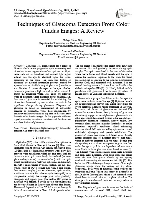
I.J. Image, Graphics and Signal Processing, 2012, 9, 44-51Published Online September 2012 in MECS (/)DOI: 10.5815/ijigsp.2012.09.07Techniques of Glaucoma Detection From Color Fundus Images: A ReviewMalaya Kumar NathDepartment of Electronics and Electrical Engineering, IIT GuwahatiE-mail: malaya.nath@, malaya@iitg.ernet.inSamarendra DandapatDepartment of Electronics and Electrical Engineering, IIT GuwahatiE-mail: samaren@iitg.ernet.inAbstract—Glaucoma is a generic name for a group of diseases which causes progressive optic neuropathy and vision loss due to degeneration of the optic nerves. Optic nerve cells act as transducer and convert light signal entered into the eye to electrical signal for visual processing in the brain. The main risk factors of glaucoma are elevated intraocular pressure exerted by aqueous humour, family history of glaucoma (hereditary) and diabetes. It causes damages to the eye, whether intraocular pressure is high, normal or below normal. It causes the peripheral vision loss. There are different types of glaucoma. Some glaucoma occurs suddenly. So, detection of glaucoma is essential for minimizing the vision loss. Increased cup area to disc area ratio is the significant change during glaucoma. Diagnosis of glaucoma is based on measurement of intraocular pressure by tonometry, visual field examination by perimetry and measurement of cup area to disc area ratio from the color fundus images. In this paper the different signal processing techniques are discussed for detection and classification of glaucoma.Index Terms—Glaucoma, Optic neuropathy, Intraocular pressure, Cup area to Disc area ratioI.I NTRODUCTIONOptic disc (OD) is the visible portion of the optic nerve, from which the nerve fibres exit the eye [1]. Disc is an inaccurate term to explain OD though optic nerve head (ONH) as it is a 3-dimensional structure. Optic nerve lies between retina and chiasm, which has four parts, such as: intraocular (the optic nerve head), intra-orbital (between globe and optic canal), intracanalicular (within the optic canal), and intracranial (between optic canal and chiasm). The OD is characterized by color, contour, and cup. The typical color of OD is orange-pink with a pale centre. Due to optic atrophy (such as:glaucoma, optic neuritis, arteritic or non-arteritic ischemic optic neuropathy or a compressive lesion) the orange pink color gradually disappears and appears pale. The healthy OD border is clear and well defined. It swells in case of papilloedema and becomes blurred in the presence of optic disc drusen. The central depression of the OD is known as the cup. It lacks of neuroretinal nerve fibres. It looks pale in color. The cup height is one third of the height of the entire disc for normal disc and gradually increases during optic atrophy. The optic nerve head is that area of the retina where nerve fibres and blood vessels exit the eye. It carries the electrical impulses to the brain for visual processing and is sensitive to the changes in intraocular pressure (IOP) and associated with glaucoma. It is the second leading cause of vision loss worldwide after diabetic retinopathy (DR) [2], [3]. Nearly half o f world’s population with glaucoma lives in Asia [4]. About 10 million people in China are suffering in glaucoma. Glaucoma is a group of conditions which damages the optic nerve on back side of the eye [3]. Optic nerve cells act as transducer and convert light signal entered into the eye to electrical signal for visual processing in the brain. The main risk factors of glaucoma are elevated IOP exerted by aqueous humor, family history of glaucoma (hereditary), myopia or nearsightedness, glaucoma in the other eye, retinal detachment, trauma to the eye, diabetes, pigmentary dispersion syndrome, narrow angles, low systemic blood pressure, migraine headaches or ocular migraines, raynaud’s syndrome, blood thickening, abnormal visual field tests, unhealthy optic nerve, corneal endothelial dystrophy and pseudo exfoliation. The amount of vision loss varies in different cases. Family history increases risk of glaucoma four to nine times, where as diabetes increases risk two times. People over the age sixty are six times more prone to glaucoma than under the age sixty. It is race dependant. African race is more likely to have glaucoma than American race [5]. The different types of glaucoma are close angle glaucoma and open angle glaucoma. Open angle glaucoma occurs when the eye fluid passes slowly by the spongy meshwork connecting the cornea and iris [6], [7]. This builds the IOP and damages the optic nerves. Close angle glaucoma occurs while the cornea and iris closes completely. Both types of glaucoma begin without any symptoms and pain. Vision loss cannot be noticeable at first. It affects the peripheral vision if left untreated. Over time it leads to tunnel vision or complete vision loss. The damage is irreversible and treatment can only reduce or prevent further damage.The diagnosis of glaucoma is done on the basis of measurement of increased IOP, visual field test,Techniques of Glaucoma Detection From Color Fundus Images: A Review 45condition of the optic nerve, and observation of variety ofpossible symptoms. These symptoms are decreasedability to see objects that are not straight ahead,decreased ability to perceive motion and to recognizecolor, etc., [1]. Increased IOP damages the cells, whichcauses vision loss. IOP [8] lies between 17 mm Hg(millimetre of mercury) to 21 mm Hg for normal eye.IOP greater than 21 mm Hg is too high for the opticnerve cells to tolerate, which exit the eye through the OD.But for the entire human, IOP greater than 21 mm Hgdoes not make damage to the vision. IOP can bemeasured by the Tonometry (Goldman ApplanationTonometry and Tonopen or non contact Tonometry). These methods of defining glaucoma do not provideaccurate measurement always as tissue damage does nothave a direct relation with IOP. So, IOP cannot be usedas a standard measure for glaucoma. It is a critical job forthe doctors to detect the vision loss or glaucoma relatedto IOP.Visual field is more specific indicator than IOP. Visualfield test is done by perimetry, which document the levelof peripheral vision. In this case the patient responds to aperceived flash of light by looking ahead every time. The accuracy of the testing depends on patient’s patience,attention and retinal sensitivity. Measurement of IOP and peripheral vision test requires patient’s attention andassessment of glaucoma cannot be guaranteed.Examination of ocular appearance is essential foraccurate assessment of glaucoma as appearance of OD isindependent on the whims of the patient but it depends onthe whims of the clinician [9], [10]. Appearance of ODdoes not fluctuate from day to day. Due to these reasonsit is treated as the most useful indicator of glaucoma andits progression. Stereoscopic disc photographs are foundto be good and have the advantage of permanent recordof the disc. Disc evaluation requires a lot of clinicalexperience for evaluation of glaucoma. Disc analysishelps in post diagnosis.Optic nerve damage can be seen in the form of cuppingof the OD. Size of the cup is related to the presence orabsence of glaucoma. Larger the cup of the optic nerve,the greater is the likelihood that the person has glaucoma.By looking into the cup-shaped optic nerve doctorscannot necessarily mean that he has glaucoma. Damagesof nerve fibre occur over a longer period (10 - 30 years).So, decrease in vision loss cannot be noticed over half ofthe nerve fibres are died. The nasal side vision is lost firstand peripheral vision loss occurs in the last part. A thorough examination of the patient’s IOP, visual field, family background and condition of the optic nerve will help the doctors to advise appropriate treatment plan for reducing further damage of the nerve fibres. Symptoms are more important than signs. Headache during reading, blurred vision, eye aches after strong exercise, poor color perception and trouble in seeing night are some important symptoms to be looked during the study of glaucoma. Analysis of OD is possible from the color fundus images which are taken by Heidelberg Retina Tomography (HRT) and Optical Coherence Tomography (OCT).Appearance of OD changes during glaucoma. In the early stage of glaucoma the changes are subtle and may appear similar to that of normal OD. Gradually the cup size increases with the progression of diseases. In early 70’s Armaly introduced the idea of cup-area-to-disc-area-ratio (CDR) i.e., proportion of the disc occupied by the cup for assessment of glaucoma [6]. It is commonly used in clinics to classify glaucoma. For normal discs it falls in the range of 0.3 to 0.5 and for glaucoma it is greater than 0.5. The sight of vision is lost completely at the CDR value 0.8. For some normal human beings CDR value lies in 0.4 to 0.6. The variation in the OD size occurs due to myopic disc and hypermetropic disc. For myopic the disc is normal, where as hypermetropic disc there is an extensive damage of nerve-fibres. In some situation one disc is normal and other disc is grossly diseased but both having same CDR. So, specific pattern of changes in the OD is used for evidence of glaucoma or progression of glaucoma with CDR. Features like focal glaucomatous optic discs, migraine, vasospasm, myopic glaucomatous discs, senile sclerotic and generalized cup enlargement are considered during assessment of glaucoma. The neuroretinal rim pattern of thickness (normal disc: inferior is thicker to superior) and areas of focal thinning (normal disc: nasal is thinner to temporal) are used for detecting glaucoma. Another characteristic of glaucoma is focal notching and during which the neuroretinal rim is absent. It is associated with peripapillary atrophy (PPA). PPA is a feature which causes rim loss in case of glaucoma during normal ageing process and high myopia. It is present with full 360degree. Senile sclerotic discs have a shallow saucerised cup with gently sloping sides and PPA. The disc also has a moth eaten neuroretinal rim. Loss of retinal nerve fibre layer (RNFL) makes the cup to expand. The different features of the OD are shown inFigure 1.Figure1. Different Parts of ODGlaucoma affects the appearance of the OD [1]. Regular analysis of OD will minimize the progression of the disease. A number of techniques have been discussed in the literature for detection of the OD and few of them mentioned about glaucoma. In this paper the different46Techniques of Glaucoma Detection From Color Fundus Images: A Reviewtechniques for glaucoma detection and classification are discussed. Section 2 explains the different techniques for glaucoma classification. Description of the freely available data and conclusions are discussed in Section 3 and Section 4 respectively.II.TECHNIQUES FOR GLAUCOMA ASSESSMENT The most reliable way of glaucoma diagnosis follows the investigation of the retina from the fundus image, which is taken by a special camera called fundus camera. Glaucoma damages the neuroretinal nerve fibres in the OD region. The progression of the disease can be obtained by analyzing the OD region. The different techniques of glaucoma classification and detection are discussed below.Gloster and Parry (1974) use the fundus image photographs for measuring the cupping in the optic disc for evaluation of glaucoma [11]. Degree of visual damage can be known from the appearance of OD. The normal eye has pale color OD. The color changes during disease condition. It appears pink during nuclear sclerosis. Three types of photographs were taken for the study, such as: ordinary photograph taken in usual manner, 80-B photograph illuminated by Kodak Wartten 80-B filter and cyan ring photograph. Different parameters (such as: CDR, cup horizontal diameter to disc horizontal diameter, cup diameter to disc diameter and cup vertical diameter to disc vertical diameter etc.,) were used to find the cupping and accessing glaucoma.Funk et al., (1989) finds the correlation between neuroretinal rim area and age in normal subjects by using Rodenstock Optic Nerve Head Analyzer (RONHA) on 194 eyes of 122 normal subjects between the age group 7 to 84 [12]. RONHA provides three-dimensional topography of OD. The total subjects were divided into eight groups. For each eye, different OD parameters such as cup-disc-ratio, disc area, cup volume, elevation and disc parameter were found out. Linear regression analysis is used to find the correlation between the neuroretinal rim areas as a function of age. But no significant linear correlation is obtained between them. There is no change in neuroretinal rim area w.r.t age. Authors found a decrease in neuroretinal rim area (less than 0.2 mm2) in case of glaucomatous damage.Neuroretinal rim area (NRA) is used for detection of glaucoma [13]. According to the literature, NRA increases with age and DR. It decreases with increase in IOP, as IOP increases the nerve swelling. NRA is calculated by taking the difference between the disc area and the cup area. Authors have used 2990 diabetic patients from 11 countries in the south central Wisconsin. They have divided the total subjects into two groups younger onset (people having diabetics before the age 30 and they are taking insulin) and older onset (people having diabetics after the age 30 and diabetics was conformed from the serum glucose level). The younger onset consists of 1210 subjects and older onset consists of 1780 subjects. From the NRA study the authors have concluded that younger onset has smaller NRA as compared to older onset. The NRA increases with age. Corona et al., (2002) overcomes the limitations for evaluation of glaucoma (such as: difficulty in interpretation of retinal images, intra and inter-observer variability, lack of proper standardization for evaluation of OD size and shape) by generating precise metrics from the stereo OD image pairs by using digital stereovision system for visualization of the structure of ONH [14]. Here authors have found the 3-D surface from 2-D stereo using different steps such as pre-processing, initial registration of stereo pair. The depth information is found out by finding area and features. The depth information of the OD is found out by power spectrum and zero mean normalized cross correlation. The correlation coefficient between manually automatic segmented cup/disc is found to be 95.7%, which implies strong overlapping. McIntyre et al., (2004) finds the Zernike moments from the color fundus images, which are taken by confocal scanning laser tomography (CSLT) for classifying the condition of the OD by using linear discriminant function derived from linear perceptron (supervised learning) [15]. Low order Zernike moments captures the gross features information from an image where as high order Zernike moments resolves the high frequency information. These features are used for classifying the glaucoma images from the normal images. Authors have used 111 healthy OD and 115 glaucoma disc for the study. Meng et al., (2005) uses the baseline matching from a query sequence for classifying visual field loss in glaucoma [16].Pueyo et al., (2006) uses neuroretinal ring and the OD area as a function of age along the different sector of the OD for detection of glaucoma [17]. The method is tested on 200 eyes obtained from Ophthalmology Hospital. The data is divided into two sets depending on IOP (normal: below 21 mm Hg, glaucoma: above 21 mm Hg). In the data set 101 images are normal and 99 images are glaucoma. According to the authors analysis temporal, superior and inferior sectors of the neuroretinal rim provide the information about glaucoma.Damages occur in the retinal nerve fibre layer (RNFL) during glaucoma is detected from the color fundus images by using computer aided detection (CAD) and Gabor filtering [18]. The diagnosis is improved due to CAD by guarding against the retinal changes. Here the authors have applied the Gabor filtering to the grey scale image of the detected OD from the color fundus image after removing the blood vessels by morphological closing. In morphological closing a circular structuring element is used whose radius is considered according to the diameter of the blood vessels. The blood vessels erased image is transformed into a rectangular array, whose x-axis represents the angle and y-axis represents the distance. Then Gabor filter is performed with a Gaussian filter to enhance the RNFL. Then the candidates are detected, whose parameters (mean angle and width of the candidates) are used as features forTechniques of Glaucoma Detection From Color Fundus Images: A Review 47classifier. This method was tested on 52 fundus images (26 images had nerve fibre layer defect) with 768 × 576 pixels. The accuracy of the method is found to be 71%. Disc morphology, such as size and shape of the neuroretinal rim and cup are varying with race, demographic characteristics, structure of optic nerve head, RNFL and glaucoma [5]. The authors have measured the disc size by histomorphometry, slit-lamp biomicroscopy, planimetry and imaging. Confocal scanning laser ophthalmoscopy (CSLO) provides the accurate measurement of OD size. For normal eye OD area ranges from 1.74 mm2- 2.74 mm2. Larger size of the disc implies larger neuroretinal rim and larger CDR. Disk size is used by Hoffmann et al., (2007) for assessment to diagnose and manage glaucoma.Fink et al., (2008) uses independent component analysis (ICA) for feature extraction from color fundus images and k-nearest neighbour classifier (KNN) for glaucoma classification [19]. ICA finds the basis images which represent the independent feature characteristic of the observed retina images of the papilla. The corresponding coefficients of basis images have been learned from a training data set. Then classification is done by KNN classifier. Here, L2norm is used for deciding the corresponding class. The technique was applied on 250 images of size 256 × 256 pixels. By this technique 90.8% images are correctly classified.Wong et al., (2009) developed an automatic cup to disc ratio measurement system ARGALI for glaucoma detection and analysis. This ARGALI technique used different segmentation method (color histogram analysis, level set method etc.,) for detection of cup and disc from the color fundus images. CDR was calculated by different methods. CDR varied for different images due to their variability. The obtained CDR by different methods is merged by adaptive neural network. This method was tested on the color fundus images (size: 3072 × 2048) taken from Singapore Eye Research Institute. Nayak et al., (2009) uses the features, such as: cup-to-disc-ratio (CDR), ratio of the distance between OD center and optic nerve head to the diameter of OD, and blood vessels area in the inferior-superior side to the nasal-temporal side (ISTN) for classifying the normal and glaucoma images by using neural network classifier [20]. These three features change due to the progression of glaucoma. The first feature CDR increases with the glaucoma due to the shifting of the ONH towards nasal side. Shifting of the ONH w.r.t to the OD center was named as distance. The ratio of the distance to the OD diameter is the second feature. Figure 2 shows the different regions (different quadrants) of the OD. Authors have used red and green channel for detection of glaucoma. At first the blood vessels are removed by morphological operation (close and open operation) as the blood vessels minimally affected by glaucoma. The OD is clearly visible in the red channel. The demarcation line between the cup and disc is not clear in red channel. So the green channel of the color fundus image is used to separate the cup from the OD. This provides the first feature. For the second feature the cropped green channel is considered. The pixel having highest intensity in the cropped green channel image is the OD centre. Bottom hat transformation is applied to the cropped green channel image. The brightest pixel in the output of the bottom hat transformation is centre of ONH. The distance between the two points is the distance defined in the paper. The ratio of the distance to the diameter of the OD is the second feature. Major parts of the blood vessels are present in the superior and inferior part of the OD. Due to shifting of ONH in glaucoma blood vessels covered by the nasal region increases and inferior-superior region decreases. So the ratio of the area of sum of blood vessels in the inferior superior region to the sum of blood vessels in the nasal temporal region decreases. The amounts of blood vessels in different quadrants of the OD are found out by applying a 300 ×300 mask on the segmented blood vessels with a rotation of 90o each time. Then third feature, ISTN is calculated. The three features are used by artificial neural network (ANN) for classification of glaucoma. The method was tested on 61 (24 normal and 37 glaucoma) fundus images from the subjects in the age of 20 to 70 obtained from Kasturba Medical College Manipal, India. The fundus images are in JPEG format with a resolution of 560 × 720. This method provides a classification rate of 90%, sensitivity 100%, specificity80% and positive predictive value of 90.9%.Figure 2. Different regions of ODJimenez et al., (2009) uses multifocal electroretinography (ERG) for studying the structural pattern of the retina for early diagnosis of glaucoma [21]. ERG is a recording of the bioelectric signals obtained due to summed activity of the retina cells. The authors have studied the peak amplitude and maximum latencies in wavelet domain for finding the diagnostic information. The ERG signal has duration of 190ms, which can be decomposed into two sections (direct component and induce component). Early changes in glaucoma can be48Techniques of Glaucoma Detection From Color Fundus Images: A Reviewdetected from the induced component (60-90 ms interval), which has three sub-components first positive wave, second negative wave and ending positive wave. The structural patterns (position of peaks, height of peaks, linear slopes, distance between the peaks and zero crossing) of the ERG data were extracted and given to the radial basis neural network (RBN) for classification. From the study authors have concluded that global analysis of morphological patterns of ERG data has provided good glaucoma discrimination. The method was tested on 50 eyes (normal: 20, glaucoma affected: 30) taken from Electro-Diagnostic Imaging San Mateo, USA. Sensitivity and specificity of this method are found to be 92% and 83% respectively.Hatanaka et al., (2011) measures the cup to disc ratio based on line profile analysis in retinal images for early detection of glaucoma [22]. Here blue channel of the color fundus image is used as it has higher contrast between the cup and rim regions. Zero crossing method is used to find the cup edge. Authors found CDR by measuring the ratio of cup diameter to disc diameter after segmenting the blood vessels erased OD from the color fundus images. This method was tested on 45 retinal images (33 glaucoma images) taken by retinal fundus camera (Kowa VX-10i) with the photographic angle of 27o. They have noted an average CDR of 0.74 and 0.59 for abnormal and normal cases respectively. In this method concordance and accuracy were found to be 85% and 94.7% respectively.Xu et al., (2011) uses a number of sliding window (ellipse) of various sizes to obtain the cup features in the OD [23]. These features are ranked by support vector machine (SVM) using radial basis function (RBF). This method attains the accuracy of 73.2%.Information theory based method, minimum-redundancy maximum-relevance (MRMR) is used by Zhang et al., (2011) for automatic diagnosis of glaucoma from color fundus images [24]. This method has used one fourth of the features for classification. MRMR provides the maximum relevant and minimum redundant features based on mutual information quotient. The classification is performed by adaptive boosting, support vector machine (SVM), linear discriminant analysis (LDA) and MRMR optimized classifiers. Here 23 features (such as: vertical cup-disc ratio, ocular hypertension, alpha PPA at optic nerve, area of optic cup, rim inferior width, medical history of glaucoma, rim temporal width, ISNT rule compliance, optic cup height, rim superior width, retinal nerve fibre layer defect, age of screening, right eye ocular hypertension, job category, anisometropia indication, diabetic retinopathy level, rim nasal width, eye history of retinopathy, PPA info, overall ocular hypertension, optic disc area, self reported heart attack and race category) are used for classification. The method was tested on the data taken from ORIGA database and Singapore Malaya eye study (SiMES). SiMES data has variation in age, gender, height, medical history, IOP, and cornea thickness. ORIGA data contains 650 retinal images. Accuracy for both SVM and LDA classifiers was found to be 92%.Nath et al., (2011) calculates CDR for detection of glaucoma [25]. In this case the green channel of the color fundus image is used for pre-processing as green channel has relative saturation at the OD region. The other regions are minimally affected. So, blood vessels are removed by the inpainting process. Then boundary of the cup and disc are determined. CDR was calculated to detect the glaucoma. The experiment was performed on 25 numbers of images consisting of 7 normal and 18 glaucoma images taken from the optic-disc-organization with 144 ×144 pixels [6]. By this method all the glaucoma images are correctly detected. This method fails while the fundus image has other pathologies.Nath et al., (2011) uses principal component analysis (PCA) and LDA for glaucoma detection and classification [26]. PCA changes the shape and location of the data. LDA provides class separability and finds decision regions among the classes. PCA finds the direction along which maximum variation of data occurs, whereas LDA finds the class scatter matrix for glaucoma classification. This method is applied to 26 images having both normal and glaucoma with 144 × 144 pixels in bit map format. Sensitivity and specificity for this method were found to be 76.92% and 66.66% respectively. The method fails in some glaucoma with inflamed disc.Bock et al., (2010) uses PCA and SVM for glaucoma classification [27]. The images are pre-processed to have the details of the OD. The pre-processing step consists of removal of blood vessels, illumination correction and optic head normalization. Then features of pre-processed images are obtained by PCA. Classification is done by SVM classifier. The images are classified to either glaucoma or non-glaucoma images. Bock et al., has found the glaucoma risk index (GRI) by combining the different feature types such as FFT, B-spline and PCA. The analysis was performed on 95 images linked to 32 eyes. The performance is calculated by accuracy, sensitivity and specificity. Accuracy, sensitivity and specificity are found to be 88%, 73% and 85% respectively.Blood vessel occlusions, ill-defined boundaries, variation in image due to pathological changes and imaging conditions are the limitations of OD segmentation. Accurate segmentation of OD and cup is essential for evaluation of glaucoma progression. Joshi et al., (2011) have proposed a novel method for cup and OD segmentation method based on vessel bends at the cup boundary from the monocular color retinal images, which gives a 2-D projection of retinal structures [28]. Vessel bends are detected by using region support concept. Here authors segment the OD based on region based active contour model. Vessel bends and pallor information is used for segmentation of cup. The method was tested on 138 fundus images (33 normal images and 105 glaucoma images) with dimension 2896×1944. The CDR and cup to disc vertical height ratio is calculated and accessed against the ground truth of three experts. The segmentation results matches to the ground truth.。
1 PRODUCT IDENTIFIER:QSE = Electro-Magnetic Flowmeter 2 TURBINE SIZE:3 FITTING:NPT = NPT (Male) (½” to 2” Only)BSP = BSPP (Male) (ISO 228) (½” to 2” Only)FAP = ANSI Flange - Polymer (3” & 4” Only)4 ELECTRONIC CHOICE:Q9 = 2-Button Integral Display with 2 Totals (Batch Total = Resettable, Total = Non-Resettable) and Rate of Flow. Also provides a Scaled Pulse Output (NPN Open Collector).42 = 2-Button Integral Display with 2 Totals (Batch Total = Resettable, Total = Non-Resettable) and Rate of Flow. Also provides 4-20 mA Output and Scaled Pulse Output (NPN Open Collector).QB = Integral Pulse Transmitter, Unscaled Pulse Output (NPN Open Collector)5 COMMUNICATION CHOICE:Q1 = QSI Module: Bluetooth®, Pulse Output (Flow or Energy and Scalable), RS485 (Modbus RTU or BACnet® MS/TP),Temperature Inputs, BTU Calculator. Energy Use Computation Note: Energy Use Computation Requires Temperature Sensor Probes (Select Probes Below). No Local Display Option.Q2 = QSI Module: Bluetooth®, Pulse Output (Flow or Energy and Scalable), Temperature Inputs, BTU (Heat) Calculator.Energy Use Computation Note: Energy Use Computation Requires Temperature Sensor Probes (Select Probes Below). No Local Display Option.Q3 = QSI Module: Bluetooth®, Pulse Output (Scalable), 4-20mA. No Local Display Option.XX = No Communication Suite. Required for Q9 and 42Electronic Choice.6 TEMPERATURE SENSOR PROBES (NOT NSF Certified):1 = Integrates with QSI Communications Choice for Energy Use Computation (2ea) 1" (25 mm) Long Temperature Sensor Probes w/Cables (10 ft. [3 m]), Used with ½" through 2" Meters2 = Integrates with QSI Communications Choice for Energy Use Computation (2ea) 2" (50 mm) Long Temperature Sensor Probes w/Cables (10 ft. [3 m]), Used with 3" and 4" Meters X = No Temperature Probes7 PACKAGING:A = 1/2" - 2" Meters with Q9 or QB Electronics Choice1/2", 3/4" and 1" Meters with 42 Electronics Choice B = 3" Meter C = 4" MeterD = 1-1/2" and 2" Meters with 42 Electronics ChoiceQSE MAG FLOWMETERThe FLOMEC ® QSE Mag Series is a dependable highly accurate electromagnetic flowmeter designed for flow and usage monitoring in commercial applications, such as wastewater that is dumped into a city sewer system.The Noryl TM housing and flow tube offer a lightweight, easy-to-install Mag Meter that is resistant to heat and compatible with many water-based liquid solutions. This plastic Mag Meter is specifically designed to be used in applications where plastic piping is used.The QSE Mag Meter monitors flow rate and total flow in a wide variety of applications including: HVAC, Turf/ Irrigation and other water reclamation applications.FEATURES / BENEFITS•Low investment and operating costs•± 0.5% Accuracy of Reading (from 0.25 fps to 15 fps [0.08to 4.6 m/s])•Wide turndown ratio of 60:1•Non-intrusive, no moving parts to wear out, low mainte-nance and repair cost, tolerates high flows without damage •The slightly modified bore permits unobstructed flow, mini-mizes flow disturbances and straight pipe requirements •Seven line sizes (½” to 4”) ½”, ¾”, 1”, 1-½”, 2”, 3", and 4” FOR INSTALLATION ON PLASTIC PIPE ONLY •Housing ported with “Thermal Well Supports” for sensors (Energy Management)•Compatible with FLOMEC Q9 Electronics Display or FLOMEC QSI I/O Board1234567>>>> QSE 30 FAP Q9 XX X B05 = ½” (15 mm)07 = 3/4” (20 mm)10 = 1” (25 mm)15 = 1-½” (40 mm)20 = 2” (50 mm)30 = 3” (80 mm) (Flange Only)40 = 4” (100 mm) (Flange Only)•Waste Water Monitoring •Agriculture Irrigation •Turf Irrigation Systems •Micro Irrigation Systems •EMS (Energy Management Systems)•Reclaimed (Recycled) Water ••Chilled water•Domestic water (hot and cold)•Energy sub-metering (BTU hot and cold)•OEM Water Treatment Skids •Cooling Tower Bleed-OffIP67© 2021 Great Plains Industries, Inc. All Rights Reserved.IND-1060-QSE Rev B 08/2021Service & Warranty: For technical assistance, warranty replacement or repair contact yourFLOMEC® or GPI® distributor: In North or South America: 888-996-3837 / Outside North or South America: +61 2 9540 4433 / 。
51-51-16U-80Issue 17Page 1 of 3UDC3200 Universal Digital ControllerModel Selection GuideInstructionsSelect the desired key number. The arrow to the right marks the selection available.Make the desired selections from Tables I through VI using the column below the proper arrow. A dot ( ) denotes availability.Key Number----_ _ _ _ _- _KEY NUMBER - UDC3200 Single Loop ControllerIf ApplicableSelection Stocking P/NDigital Controller for use with 90 to 250Vac Power DC3200 Digital Controller for use with 24Vac/dc PowerDC3201TABLE I - Specify Control Output and/or AlarmsTABLE II - Communications and Software Selections0 _ _ _1 _ _ _2 _ _ _3 _ _ _ _ 0 _ __ A _ __ B _ __ C _ _No Selection_ _ 0 __ _ _ RInfrared interfaceInfrared Interface Included (Can be used with a Pocket PC)Software SelectionsStandard Functions, Includes Accutune Math OptionSet Point Programming (1 Program, 12 Segments) Set Point Programming Plus Math Reserved Solid State Relay (1 Amp) Plus Alarm 1 (5 Amp Form C Relay)_ A Open Collector Plus Alarm 1 (5 Amp Form C Relay)_ TCommunicationsNoneAuxiliary Output/Digital Inputs (1 Aux and 1 DI or 2 DI)RS-485 Modbus Plus Auxiliary Output/Digital Inputs10 Base-T Ethernet (Modbus RTU) Plus Auxiliary Output/Digital Inputs T _Dual 2 Amp Relays (Both are Form A) (Heat/Cool Applications)R _Output #2 and Alarm#1 or Alarms 1 and 2No Additional Outputs or Alarms _ 0One Alarm Relay Only_ B E-M Relay (5 Amp Form C) Plus Alarm 1 (5 Amp Form C Relay)_ E DescriptionAvailabilityOutput #1Current Output (4 to 20ma, 0 to 20 ma) C _Electro Mechanical Relay (5 Amp Form C)E _Solid State Relay (1 Amp)A _Open Collector transistor output_ _ _ _ _ __ __ _ _ __ _ __ _IIIIIIIVVVIUDC3200 ControllerNew! Easy To Use UDC3200 1/4 DIN Single Loop ControllerThe UDC3200 Controller packs new powerful features while retaining all the simplicity and flexibility of the industry standard UDC3300 Controller. Many new optional features include: - Enhanced Display- Built-in infrared communications port for configuring with a Pocket PC or Laptop - PC Based Configuration Tools - Ethernet Communications - Two Analog Inputs- Accutune III, Fast/Slow, Heat/Cool - Thermocouple Health Monitoring51-51-16U-80Issue 17Page 2 of 3ORDERING INSTRUCTIONS: These are provide as guidance for ordering such as those listed1. Part numbers are provided to facilitate Distributor Stock.2. Orders may be placed either by model selection or by part number.3. Part numbers are shown within the model selection tables to assist with compatibility information.4. Orders placed by model selection are systematically protected against incompatibility.5. Compatibility assessment is the responsibility of the purchaser for orders placed by part number.6. Items labeled as N/A are not available via the stocking program and must be ordered by model selection.AvailabilitySection 5Page: UDC-79Page 1 of 3UDC3200Supplemental Universal Digital Controller Accessories & Kits。
图1 微调网络流程从流程图可看出,本文使用的迁移学习,除最后一个完全连接层外,所有来源模型的层都复制到本文的目标网络,并修改最后的全连接层,使模型适应于服装图像分类任务。
本次实验中,训练开始前将所有输入图像尺寸归一化为,将图像随机拆分为80%的训练集、20%的验证集,通过旋转等操作增强图像数据,通过卷积和池化操作提取图像特征。
为了在新层中更快学习,增加全连接层的学习速率因子,并将初始学习率设置为0.001。
网络训练方面,训练,batch size为128,最初学习,每次更新后学习率都会降低。
训练过程中精度和损失度变化如图2所示。
图2中左侧纵轴是训练和验证过程中的损失度,右侧纵轴是训练和测试过程中精确度,横轴为35个epochs中的loss,绿色代表测试过程中的型测试的accuracy。
从图中可看出,测试精度趋于略优于基于CNN模型的网络。
2 结 语本文通过在训练好的CaffeNet实现服装图像类别较为精准的分类,解决了手工设计特征过程中存在的误差问题,提高了分类精度和速度。
但是,目前对服装图像的研究还存在集稀缺、标注信息少、服装定位响分类精度和速度,有很大改基于深度学习的服装图像分类方向。
参考文献[1]刘聪,丁贵广.基于视觉的服装属性分类算法[J].微电子学与计算机,2016,33(1):28-33.图2 训练及测试过程精度及损失度变化 [2]刘晨,曲长文,周强,等.基于卷积神经网络迁移学习的SAR 图像目标分类[J].现代雷达,2018(3):38-42.通信领域现如今,通信行业的主要发展目标是融合声音、文字的通信。
其中,图像通信是最复杂的技术领域。
图像数据量较较广,目前智能电视机信号传输必须达到100 M/s 以上,想要把输送高速数据,必须使用编码技术压缩信息量。
军事领域军事行业,图像识别处理技术主要分布在导弹、照片解读、具备图像传输的自动化军事系统等。
目前,公安系统融入了图像识别技术,主要应用于人脸识别、图片复原等方面,6 结 语计算机图像识别技术给人们的日常生活带来了很大便利。