SE350中文说明书
- 格式:pdf
- 大小:361.54 KB
- 文档页数:8
ES350, ES400, ES350带氩气功能电刀ES350带氩气模块和血管闭合系统®功能电刀电外科设备使用说明书使用之前请阅读该手册,并以此作为进一步的参考。
2说明书中使用的标志:重要信息允许禁止 警告内容1. ES350的预期用途 (5)2. 电外科手术基础 (7)2.1 单极操作 (7)2.2 双极操作 (7)2.3 符号 (8)2.4 电外科配件 (9)3. 技术规格 (11)4. 设备列表 (13)5. 外表和结构 (14)6. 启动前的准备工作 (21)6.1 连接电源 (21)6.2 连接气管 (23)6.3 设置氩气气流 (23)6.4 功率设定 (24)6.5 典型的功率设定 (25)7. 操作设备,进行外科手术 (26)7.1 打开设备 (26)7.2. 调节声音 (26)7.3 中性电极监测 (27)7.3.1中性电极监测系统 (27)7.3.2 一次性两片式电极 (27)7.3.3 多次性一片式电极 (28)7.3.4 中性电极适用原则 (30)7.4 电刀过载控制 (32)7.5 单极切割 (33)7.6 单极凝血 (34)7.7 氩气凝血 (36)7.8 双极凝血 (36)7.8.1自动操作 (37)7.8.2 脚踏控制操作 (37)7.9 血管闭合系统® (38)7.10 双极切割 (39)7.11 息肉切除术和乳头切开术 (41)7.12 使用记忆设置 (43)7.13 多功能脚踏开关 (43)7.14 关闭设备 (44)8. 保护方式和警告 (44)9. 技术参数 (47)10. 设备和配件维护 (49)10.1 推荐的多次性电外科配件的清洁和消毒机构 (49)10.1.1 手动清洁 (50)10.1.2 机械清洗 (50)11. 环境需求 (51)12. 环境保护指南 (51)341. Intended use for the ES350 unitsES350 混合氩气模块ES3501.ES350的预期用途ES350电刀是一款通用型透热仪器,使用高频电流,主要用于电外科手术。
SE350发电机自动调压板使用手册版本 1.0日期:2015/06/27SE350版本历史记录:日期版本内容2015-06-27 1.0首次发行目录2.技术参数 (3)3.尺寸图 (4)4.接线 (5)3.1.励磁场接线“+、一” (5)3.2.检测&电源输入“3、4” (5)3.3.外接电压调节器“6、7” (5)3.4.低频保护一频率选择“50/60” (5)5.操作说明 (6)6.测试图: (8)1.技术参数项目参数说明电源检测输入电压85-135VAC/190-r240VAC单相频率50/60Hz以跨接线设定电压选择指拨开关选择120/240VAC输出电压120VAC输入时最大36VDC240VAC输入时最大73VDC电流连续4A非连续为10秒内7A(52/105VDC)电阻最小15Ohm最大100Ohm电压建立在AV R输入端子需剩磁电压5VAC以上,25Hz EMI抑制内建与突波吸收器与滤波器调压精度<士1%(发动机转速变动在4%内)外部电压调节用1K Ohms1Watt电位器时为士5%用2K Ohms1Watt电位器时为士10%消耗功率最大8Watt低频保护50Hz系统转折点为45-51Hz60Hz系统转折点为54-61Hz(*拐点值为出厂设定值)尺寸99.5mm L*67mm W*47.5mm H重量0.3KG2.尺寸图图一3.接线3.1.励磁场接线“+、一”(1)将调压板上注“F+”之引线连接于励磁机磁场“+”,将注“F-”引线连接至磁场“一”。
注:励磁机磁场直流电阻为15-100Ω。
(2)如果磁场电阻小于15Ω且在发电机全载时,磁场电压小于70V DC时可串接一适当瓦数(W)的电阻,使磁场总电阻为15一100Ω。
3.2.检测&电源输入“3、4”调压板上注“3、4”引线接至发电机组绕组,可由电压选择开关选择120或240VAC系统。
3.3.外接电压调节器“6、7”(1)调压板内部提供一发电机电压粗调预设旋钮(VOLT),顺时针方向增加。
NexION 350 ICP-MS 用户操作指南用户操作指南说明本操作指南适用于珀金埃尔默公司电感耦合等离子体质谱(NexION350系列)的操作与使用。
参考资料:Hardware GuideSoftware GuideService Guide。
✓本文件禁止以任何形式在未经许可的情况下拷贝、复印。
✓欢迎您对本文件提出宝贵的修改意见。
✓本文件仅供您参考。
1ICP-MS技术与原理1.1原子光谱技术火焰原子吸收光谱(FAAS)石墨炉原子吸收光谱(GFAAS)电感耦合等离子体发射光谱(ICP-OES/AES)电感耦合等离子体质谱(ICP-MS)1.2电感耦合等离子体质谱(ICP-MS,Inductively Coupled Plasma MassSpectrometry)如未特别指出,ICP-MS一般指的是以四级杆为质量分析器的ICP-QMS。
此外,还有高分辨质谱(HR-ICP-MS),MC-ICP-MS,ICP-TOF-MS等。
部分国内外出版物1.2.1 ICP-MS技术ICP-MS是以独特的接口技术将电感耦合等离子体(ICP)的高温电离特性与四极杆质量分析器(MS)的快速灵敏扫描的优点相结合而形成一种元素和同位素分析技术。
电感耦合等离子体(ICP)等离子体指的是含有一定浓度阴阳离子能够导电的气体混合物。
在等离子体中,阴阳离子的浓度是相同的,净电荷为零。
通常用氩形成等离子体。
氩离子和电子是主要导电物质。
最高温度可以达到10,000K。
Induction zone四级杆质量分析器(MS)测定时样品由载气(氩气)引入雾化系统进行雾化后,以气溶胶形式进入等离子体中心区,在高温和惰性气氛中被去溶剂化、汽化解离和电离,转化成带正电荷的正离子,经离子采集系统进入质谱仪,质谱仪根据质荷比进行分离,根据元素质谱峰强度测定样品中相应元素的含量。
1.2.2 ICP-MS技术特点ICP-MS是目前发展最快的痕量元素分析技术。

ThinkSystem SE350 Purpose-built IoT, Edge serverPurpose Built Edge Server for Compute & StorageToday, remote locations are forced to make a choice between underpowered IOT gateways and PCs, or overpowered and non-rugged datacenter centric servers. Now they have an option—a right-sized compact compute and storage server designed specifically to meet the needs of remote locations. The Lenovo ThinkSystem SE350 is an Intel® Xeon® D-2100-based 1U height, half-width, and short-depth Edge server that can go anywhere. It can be hung on a wall, stacked on a shelf, or mounted in a rack. This rugged Edge server can handle temperatures from0-55°C as well as tolerance to locations with high-dust and vibration.The SE350 is designed to virtualize traditional IT and OT applications as well as new transformative IOT and AI systems, providing the processing power, storage, accelerator, and networking techniques required for today’s Edge workloads.Secure, Connected and ReliableAt Lenovo, security begins with design and continues through supply chain, delivery, and the full lifecycle of the system.The SE350 equips ThinkShield security with cybersecurity capabilities with key encrypted storage and secured bios, and physical security capabilities such as a locking bezel, intrusion and tamper protection mechanisms.The SE350 provides numerous connectivity options with wired and secure wireless Wi-Fi and LTE connection abilities. Reliability features such as wireless failover, redundant boot and data drives, high temperature components and support for hyperconverged clustering keep critical Edge workloads running.Agility and Remote ManageabilityIt is costly and time consuming to send IT staff to remote sites. The SE350 features XClarity Controller, an enterprise-grade embedded management engine. It also supports XClarity Administrator, which enables IT managers to efficiently maintain server, storage, and networking infrastructure and accelerate services provisioning.In addition to a dedicated wired networking management port, the SE350 can deliver management over a secure wireless connection so IT managers can perform updates, management tasks, and access sites even when the primary site internet connection isdown.© 2023 Lenovo. All rights reserved.Availability: Offers, prices, specifications and availability may change without notice. Lenovo is not responsible for photographic or typographic errors. Warranty: For a copy of applicable warranties, write to: Lenovo Warranty Information, 1009 Think Place, Morrisville, NC, 27560. Lenovo makes no representation or warranty regarding third-party products or services.Trademarks: Lenovo, the Lenovo logo, ThinkAgile®, ThinkShield®, ThinkSystem®, TruDDR4, and XClarity® are trademarks or registered trademarks of Lenovo. Intel® and Xeon® are trademarks of Intel Corporation or its subsidiaries. Microsoft®, Windows Server®, and Windows® are trademarks of Microsoft Corporation in the United States, other countries, or both. Other company, product, or service names may be trademarks or service marks of others.Document number DS0088, published August 12, 2020. For the latest version, go to /ds0088.。

t esto 350-EPA,-Pro手操器和testo 350-EPA,-Pro/-XL烟气分析箱操作手册 中文2 一般说明一般说明请仔细阅读本文,以便在投入使用前,先熟悉产品的操作。
如有必要,请把本手册放在手边,以供取阅。
本文描述了testo 350-EPA,-Pro 测量系统的操作说明。
Testo 350-XL 的一些标准功能,对于testo 350-EPA,-Pro 烟气分析仪来说则是选配功能。
两种烟气分析仪分别使用testo 350-EPA,-Pro 手操器。
也就是说,本手册描述的功能和操作,适用于testo 350-EPA,-Pro 手操器和testo 350-EPA, Pro 烟气分析箱。
提示标识含义建议警告:warning!如果未采取特定的预防措施,可能会引起严重的人身伤害请仔细阅读警告提示,采取预防措施警告:warning!如果未采取特定的预防措施,可能会造成轻微的人身伤害,或设备损坏请仔细阅读警告提示,采取预防措施重要信息请特别注意Text仪器屏幕显示文字 -按键请按键打印的功能键 请按功能键简明版操作步骤 见简易格式,3页一般说明简易格式本手册使用一些简易格式,来描述操作步骤(例如,调用功能)例如:调用诊断功能简易格式:要求的操作步骤:1.打开主菜单:2.选择菜单项:3.确认选择:4.选择功能诊断:5.确认选择:34 内容内容一般说明 (2)内容 (4)A. 安全说明 (8)B. 预定用途 (9)C. 产品描述 (10)手操器 (10)C.1C.1.1 手操器概述 (10)C.1.2 键盘 (11)C.1.3 显示屏 (11)手操器连接/接口 (14)C.1.4手操器电源 (14)C.1.5烟气分析箱 (15)C.2C.2.1 烟气分析箱概述 (15)C.2.2 LED状态显示灯 (16)C.2.3 烟气分析箱连接/接口 (16)烟气分析箱供电 (17)C.2.4功能/仪器选项 (17)C.2.5烟气探针 (17)C.3D 调试 (18)E 操作 (19)电源,电池/充电电池 (19)E.1更换电池 (19)E.1.1电池充电 (20)E.1.2电源供电 (21)E.1.3E.2探头传感器 (21)E.2.1 连接探头传感器 (21)E.2.2 使用烟气探针 (21)内容5 E.3 基本操作步骤 (22)连接系统部件 (22)E.3.1打开测量系统 (23)E.3.2调用功能 (24)E.3.3分配功能键 (25)E.3.4输入数值/名称 (26)E.3.5打印数据 (27)E.3.6E.3.7保存数据 (27)E.3.8关闭测量系统 (27)E.4 设置测量系统 (28)E.4.1设置语言 (28)设置日期/时间 (28)E.4.2设置燃料 (28)E.4.3编辑显示 (29)E.4.4设置地点 (30)E.4.5更改仪器名称 (31)E.4.6设置打印机 (31)E.4.7E.5 日常保养 (32)E.5.1冷凝槽/冷凝箱 (32)检查/替换过滤芯 (33)E.5.2E.5.3检测系统泄露 (33)F. 主菜单 (34)内存 (34)F.1F.1.1 读取 (34)F.1.2 程序 (34)F.1.3 删除内存 (36)F.1.4 释放内存? (36)F.2传感器 (36)F.2.1 校准 (36)F.2.2 打印传感器数据 (39)F.2.3 传感器状态 (39)输入 (39)F.3F.3.1 测量点编号/HCT (39)F.3.2 燃料 (40)F.3.3 O2参考值/CO2max (40)F.3.4 参数 (40)F.3.5 稀释 (41)F.3.6 露点/环境空气 (41)6 内容装置 (42)F.4F.4.1 更改日期 (42)F.4.2 视图 (42)F.4.3 打印机 (42)F.4.4 诊断 (43)F.4.5 配置 (43)F.4.6 密码 (43)服务 (44)F.5F.5.1 操作值 (44)F.5.2关闭 (44)地址 (44)F.5.3F.5.4 设备数据 (44)F.5.5 语言 (45)F.5.6 数据传输总线地址 (45)G. 测量 (46)准备测量 (46)G..1烟气测量 (47)G..2抽力/差压测量 (47)G..3风速测量 (48)G.4温差测量 (49)G.5测量编程/固体燃料测量 (49)G.6H. 保养和维修 (50)清洁仪器 (50)H.1更换/翻新传感器 (50)H.2重新校准传感器 (51)H.3清洁烟气探针 (51)H.4替换探针前置过滤器 (52)H.5替换热电偶 (52)H.6更换打印纸 (52)H.7更换电池/充电电池 (52)H.8H.9更换冷凝泵 (53)I. 问与答 (54)内容7J. 技术数据 (55)标准和测试 (55)J.1量程和精度 (55)J.2其他仪器数据 (57)J.3J.4计算原理 (58)J.4.1 燃料参数 (58)J.4.2 计算公式 (58)推荐的清洗时间 (61)J.5K. 附件/备件 (62)8 A. 安全说明A. 安全说明避免电气危险:> 不要在有电部件上或其附近使用本测量仪器和探头进行测量保护仪器:> 不要将测量仪器/测量元件与溶剂放在一起,并且不要使用任何干燥剂。

SE350VOLTAGE REGULATOR INSTRUCTION MANUALINTRODUCTIONThe SE350 voltage regulator is an encapsulated electronic voltage regulator that controls the output of a brushless AC generator by regulating the current into the exciter field. SPECIFICATION SE350 REGULATORSensing & Power Input190-240 VacBurden500 VAOutput Power- Continuous 73 Vdc at 3.5 Adc (255w)Output Power - Forcing(240 Vac Input Power)105 Vdc at 5 Adc (525w)Regulation 1 .0%Remote Voltage Adjustment Range± 10% with 2000 ohm rheostat± 5% with l000 ohm rheostat Frequency Compensation AdjustableRoll off frequency54-61 Hz for 60 Hz45-51 Hz for 50 HzOperation Weight6.5 oz.Operating Temperature- 40°C to + 60°CStorage Temperature- 65°C to + 85°CPower Dissipation8 watts maximumSize 3.94" L X 2.66” W X 2.20: HVoltage Buildup Internal provisions forautomatic voltagebuild up from generator residual voltage aslow as 10 Vac.EMI Suppression Internal Electromagnetic InterferenceFilter (EMI Filter )WARNINGTO PREVENT PERSONAL INJURY OR EQUIPMENTDAMAGEONLY QUALIFIED PERSONNEL SHOULDINSTALL, OPERATE, OR SERVICE THIS DEVICE.CAUTION: DO NOT megger or high-pot the generator with the regulator connected.DO NOT high-pot the regulator.The SE350 voltage regulator can be mounted in any plane, following are mounting dimensions.FIGURE 1FUSEA 4 Amp, 250 V, 5 X 20 mm fuse is supplied with the regulator (Part A-527066).It can be located on the rear face of the voltage regulator.EXCITER POWER CIRCUITConnect the regulator wire F+ to the generator F+ or Fl field terminal.Connect the regulator wire F- to the generator F- or F2 field terminal.See Figure 2 for typical connection diagramSENSING/POWER INPUT CIRCUITInput power and sensing is achieved through terminals 3 and 4.The voltage input requirement of the SE350 is 190 to 240 Vac. See Figure 2FIGURE 2VOLTAGE ADJUSTThe screwdriver adjustable potentiometer adjusts the generator output voltage. Adjustment clockwise increases the generator output voltage.When using a remote voltage adjust rheostat, remove the jumper wire across terminals 6 and 7 and install a 2000 ohm 1/2 watt (minimum) rheostat. This will give ±10% voltage variation from the nominal. (For ±5% voltage variation use a 1000 ohm 1/2 watt rheostat). See Figure 2. STABILITY ADJUSTSystem stability is the ability of the generator to respond to load transients. Decreasing the stability makes the generator less sluggish and faster to respond to toad transients. If the stability of the regulator is decreased too much, the generator will tend to hunt under steady state conditions.The screwdriver adjustable potentiometer adjusts the system stability. Adjustment clockwise increases the stability. Increasing the stability increases the response time of the generator. Conversely, decreasing the stability decreases the response time of the generator.V/HZ ROLL-OFF FREQUENCY SELECTIONThe roll off point is the frequency where the generator voltage starts to decrease. This reduces the Kilowatt load to the engine, which allows the engine to recover in speed under any load transient condition. Use jumper to select 50 HZ or 60 Hz. The screwdriver adjustable potentiometer sets the roll-off frequency from 54-61 Hz in the 60 Hz setting or from 45-51 Hz in the 50 Hz setting.The SE350 has the roll-off point preset to 58 Hz in the 60 Hz mode and 48 Hz in the 50 Hz mode. To change the roll-off point, adjust engine speed to the desired rated speed. (50 or 60 Hz). Set the voltage to the desired setting at rated speed. Adjust engine speed to the desired roll-off point. Turn the potentiometer counterclockwise until the voltage starts to drop off. Then adjust the potentiometer clockwise until the voltage returns to rated voltage. Re-adjust engine speed to rated speed.PRELIMINARY SET-UPEnsure the voltage regulator is correctly connected to the generator. Refer to the specific connection diagram supplied with the generator.Set the regulator voltage adjust to full counter-clockwise (minimum voltage level).Set the remote voltage adjust (if used) to the center position.Set the stability control full clockwise (maximum stability level).Connect the positive lead of a 100 V D.C. voltmeter to Fl and the negative lead of the voltmeter to F2 or use an appropriate AC voltmeter on the generator output leads.SYSTEM START-UPStart and run the generator at no load and rated speed. The generator voltage should build up to a minimum level. (Actual level is dependent upon connection). If it does not build up, refer to field flashing section in generator manual.Slowly adjust the voltage control until the generator voltage reaches the nominal value. If used, adjust the remote voltage rheostat to set the generator voltage to the exact value desired.Turn the stability adjust counter-clockwise until instability is shown on either of the voltmeters mentioned in the “PRELIMINARY SET-UP” section. With the system operating in an unstable condition, slowly adjust the stability control clockwise until generator stability is reached.Interrupt regulator power for a short time (approximately 1-2 seconds).If the generator remains stable, no further adjustment is necessary. If the generator does not remain stable, increase the stability slightly and interrupt regulator power again.This procedure should be repeated until system stability is reached and maintained.TROUBLESHOOTINGSymptom Cause ActionResidual Voltage -No Output Residual voltage at regulator powerinput wires 3 & 4 below 10 V ac.Acceleration time to rated speed toolong.Field leads Fl, F2 not connected.Power input leads not connected.Blown or missing fuse.Defective regulator.Defective generator.Check wiring diagram forproper connections.Flash generator field. Refer tofield flashing section ingenerator manual.Reduce acceleration time.Interrupt power input toregulator after achieving ratedspeed.Connect field leads Fl, F2.Connect power-input leads 3,4.Replace fuse.Replace regulator.Consult generator manual.Output Voltage Low Incorrect connections.Voltages adjust turned down.Remote voltage adjust is turneddown.Defective regulator.Check wiring diagram for proper connections.Rotate voltages adjust CW until desired voltage is reached.Rotate remote voltages adjust CW until desired voltage is reached.Replace regulator.Output Voltage High Voltages adjust turned too high.Remote voltage adjust is turned toohigh.Rotate voltages adjust CCW until desired voltage is reached. Rotate remote voltages adjust CCW until desired voltage is reached.Output Voltage High -No AdjustmentDefective regulator.Replace regulator.Remote Voltage Adjust Operates Backwards Voltages adjust wire backwards.Reverse the wiring of theremote voltage adjust.Generator Output Voltage Hunting Stability adjusts not set properly.Rotate the stability adjusts in aCW direction until huntingstops.Poor Regulation Defective regulator.Replace regulator.。
INSTALLATION MANUALES-350-OWLCR-M ES-350-OMLCR-LES-350-SNDBAR-30-BLK ES-350-SNDBAR-40-BLK ES-350-SNDBAR-50-BLK ES-350-SNDBAR-60-BLK ES-550-SNDBAR-40-BLK ES-550-SNDBAR-50-BLK ES-550-SNDBAR-60-BLK ES-550T-SNDBR-40-BLK ES-550T-SNDBR-50-BLK ES-550T-SNDBR-60-BLKpage | 2 Support 866.838.5052page | 3© 2018 Episode®A. Read these instructions.B. Keep these instructions.C. Heed all warnings.D. Follow all instructions.E. Do not use this apparatus near water.F. Clean only with dry cloth.G. Do not block any ventilation openings. Install in accordance with the manufacturer’s instructions.H. Do not install near any heat sources such as radiators, heat registers, stoves, or other apparatus (including amplifiers) that produce heat.I.Do not defeat the safety purpose of the polarized or grounding type plug. A polarized plug has two blades with one wider than the other. A grounding type plug has two blades and a third grounding prong. The wide bladed or the third prong are provided for your safety. If the provided plug does not fit into your outlet, consult an electrician for replacement of the obsolete outlet.J. Protect the power cord from being walked on or pinched particularly at plugs, convenience receptacles, and the point where they exit from the apparatus.K. Only use attachments/accessories specified by the manufacturer.L. Use only with the cart, stand, tripod, bracket, or table specified by the manufacturer, or sold with the apparatus. When a cart is used, use caution when moving the cart/apparatus combination to avoid injury from tip-over.M. Unplug this apparatus during lightning storms or when unused for long periods of time.N.Refer all servicing to qualified service personnel. Servicing is required when the apparatus has been damaged in any way, such as power-supply cord or plug is damaged, liquid has been spilled or objects have fallen into the apparatus, the apparatus has been exposed to rain or moisture, does not operate normally, or has been dropped.O. The equipment shall be used at maximum 45 degree C ambient temperature.P. To reduce the risk of electrical shock, do not open the equipment. For safety reasons it is only allow to the opened by qualified service personnel.Q. WARNING:To reduce the risk of fire or electric shock, do not expose this apparatus to rain or moisture. Additionally, the apparatus shall not be exposed to dripping or splashing and no objects filled with liquids shall be placed on the apparatus.R. The mains plug is used as the disconnect device and shall remain readily operable.S. The product shall be used on open bench.T. No naked flame sources, such as lighted candles, should be placed on the apparatus.U.The apparatus should be connected to a mains socket outlet with a protective earthing connection.page | 4OVERVIEWWelcome to Episode® Speakers. We appreciate your purchase and are committed to providing the highest-quality products possible.The Episode® Soundbar models are a superb choice for almost every type of home theater or home audio installation.They have been designed with advanced technological components that allow for high performance and a lifetime of enjoyment.IMPORTANT INSTRUCTIONS AND CONSIDERATIONSRead and understand all instructions.Before beginning installation, carefully plan location accounting for potential electrical, plumbing or other obstacles.RECOMMENDED AMPLIFIER POWERTo get the best performance from the Soundbar, an amplifier or receiver with the following power rating is recommended:ES-350-OWLCR-M – between 20 and 100 Watts RMS per channelES-350-OMLCR-L – between 20 and 100 Watts RMS per channelES-350-SNDBAR-30-BLK – between 20 and 100 Watts RMS per channelES-350-SNDBAR-40-BLK – between 20 and 100 Watts RMS per channelES-350-SNDBAR-50-BLK – between 20 and 100 Watts RMS per channelES-350-SNDBAR-60-BLK – between 20 and 100 Watts RMS per channelES-550-SNDBAR-40-BLK – between 20 and 100 Watts RMS per channelES-550-SNDBAR-50-BLK – between 20 and 100 Watts RMS per channelES-550-SNDBAR-60-BLK – between 20 and 100 Watts RMS per channelES-550T-SNDBR-40-BLK – between 20 and 100 Watts RMS per channelES-550T-SNDBR-50-BLK – between 20 and 100 Watts RMS per channelES-550T-SNDBR-60-BLK – between 20 and 100 Watts RMS per channelSPEAKER WIRETo connect the Soundbar to an AV Receiver or Amplifier, high-quality 14 to 16 gauge stranded speaker wire is recommended. The wire may be connected directly to the speaker’s removable screw-down terminals. Remember that you will need 3 runs of speaker wire to the Soundbar location as it contains the left, center, and right speaker.A special wire management channel has been included in the rear of the speaker so that a wall mounted speakercan sit flush on the wall.FEATURES• Replaces Left, Center, and Right channels in one convenient speaker• Extremely Low-Profile, Extruded Aluminum Cabinet• Knockout for Hidden IR Receiver• Flexible Mounting Options• Cabinet Top or Shelf Placement with included kickstands• On-Wall with included mounting plate• Flat-Screen with optional accessory that attaches to TV mountWHAT’S INCLUDED• (1) ES-350-SNDBAR-XX, ES-550-SNDBAR-XX, or ES-550T-SNDBR-50• (2) Kickstands for Cabinet placement• (2) Shoulder bolts for Kickstand and Wall Plates• (2) Large Flat Washers for Kickstands• (2) Rubber Feet• (1) Wall Plate Bracket with adjustable knobs• (4) Wood Screws for Wall Plate• (4) Small Flat Washers for Wall Plate• (1) IR Receiver Spacer Support 866.838.5052page | 5© 2018 Episode®INSTALLATION SPEAKER PLACEMENTThe ES passive series of soundbars are designed to be the Left, Center, and Right speakers of a home theater surround system. For most applications, placement should be below a flat screen TV on a cabinet top or shelf. Other options for placement include On-Wall using the included bracket, or attached to a Flat Panel mount using the optional Strong mount bracket.INSTALLING ON OR IN A CABINETConsiderations for PlacementWhen placing the Soundbar on a cabinet shelf, the front edge of the speaker should be flush with the front of the shelf. Placing the speaker further back on the shelf will degrade the sound quality of the speaker. Attaching the KickstandThe kickstand for the Soundbar allows for the angle of the Soundbar to be adjusted to maintain proper audio performance. When placing the Soundbar, adjust the kickstand height to angle the Soundbar towards the listener’s ears. See Adjusting the Kickstand for more information.1. Place the included Kickstands on the rear of Soundbaras shown. 2. U sing a shoulder bolt and washer for each Kickstand, tighten to secure the Kickstand to the Soundbar.Attaching the FeetTo ensure that the Soundbar will not slip when using the kickstands, (2) rubber feet have been included. The feet must be installed when using the kickstand. Place the feet 3” from the left and right outer edge, and ¼” from the front edge of the Soundbar.Note: When using the kickstand in the inverted position, thefeet should be placed at the front edge of the speakerNon-Inverted Kickstand Inverted Kickstandpage | 6Adjusting the KickstandAfter installing the kickstand and placing the Soundbar, adjust the angle of the speakers towards the listener’s ears.If the speakers point away from the listener’s ears, slide the kickstand up or down to achieve the proper angle. Note that the kickstand can be inverted when the Soundbar is pointing down.Mounting on a Wall Support 866.838.5052page | 7© 2018 Episode®CONSIDERATIONS FOR WALL MOUNTINGTo maintain a high level listening experience, the Soundbar should be as close to the TV as possible. Placing To maintain a proper listening experience, the Soundbar should be as close to the TV as possible. Placing the Soundbar more than 3” from the screen will separate the audio from the video and provide a poor viewing and listening experience, keep this in mind when locating the Soundbar.Before Installing the Mount• Locate and install the TV mount.• With the TV on the mount• Mark the position of the bottom of the TV.• Mark the position of the TV’s Center Point.• Remove the TV from the mount Attaching the Wall BracketNote: For ease of installation of the bracket and the Soundbar, we recommend that the TV be removed from the mount. This allows for the Soundbar to be placed properly.INSTALLING THE MOUNT (ES -550, AND ES -350)1. Locate wall studs using a stud finder (not included).2. Place the Bracket on the wall with the flat side towards the wall. Ensure the center of the bracket is lined upwith the center point of the installed television.3. Position the center of the bracket 2 ¼ ” from the bottom of the TV. This will place the Soundbar flush with thebottom of the TV when installed.Tip:T o allow for extra clearance, position the center of the bracket, 2 5/16” from the bottom of the TV. This will provide an extra 1/16” clearance (recommended for Tilt Mounts) allowing for any tolerance differences that may occur.4. Level the bracket and attach it to the wall studs using the horizontal screw hole slots. All 4 screws should beused, making sure to keep the bracket flat to the wall and securely attached.5. Attach the Soundbar to the bracket by placing the bracket’smounting bolts into the keyhole slots on the rear of the soundbar and dropping the Soundbar into place.Note:O nce installed, if the soundbar needs upward adjustment, the soundbar will need to be unattached from the bracket.To Adjust:Remove the soundbar from the bracket, then adjust the thumbscrews on the bracket by hand or using a flathead screwdriver if necessary.Replace the soundbar when adjustment is complete.Repeat the process if further adjustment is necessary.page | 8INSTALLING THE MOUNT (ES-500T)1. Locate wall studs using a stud finder (not included).2. Place the Bracket on the wall with the flat side towards the wall and the notched center mark facing up. TheSoundbar Center mark should be located at the center point of the installed television.3. Position the Bracket Vertical Center (C) v groove 2 ¼ ” from the bottom of the TV. This will place theSoundbar flush with the bottom of the TV when installed.Tip: T o allow for some extra clearance, position the Bracket Vertical Center (C), 2 5/16” from the bottom of the TV. This will provide an extra 1/16” clearance (recommended for Tilt Mounts)allowing for the any tolerance differences that may occur.4. Level the bracket and attach it to the wall studs using the horizontal screwhole slots. All 4 screws should beused, making sure to keep the bracket flat to the wall and securely attached.5. Attach the Soundbar to the bracket by placing the bracket’s mounting boltsinto the keyhole slots on the rear of the soundbar and dropping the Soundbarinto place.ATTACHING THE WALL BRACKET (ES-350-OWLCR)A wall mounting template has been included; use this template for proper and accurate positioning of the OWLCR.1. Locate wall studs using a stud finder (not included).2. Position the provided template on the wall in the desired location of the speaker. If the location does not allowfor this, use a wall molly or anchor with the appropriate weight rating for the Soundbar.3.Level the template and mark the wall with the screw locations. Support 866.838.5052page | 9© 2018 Episode®4. Secure the brackets to the wall.5. If mounting the OWLCR in a horizontal orientation, place the provided rubber bumpers in line with the bracketsat the bottom of the speakers. These are not needed when mounting in an vertical orientation.6. Place the Speaker onto the wall brackets with the rear screws in the slots. Slide the speaker onto the bracket.Your install is now complete.Slide OWLCRInstalling on a Flat Panel MountThe ES passive series of soundbars can be mounted directly to a Flat Panel Mount with the Strong™ SM-SBAR2-BKT-UNIV (available separately). Using the Flat Panel mount bracket allows for the speaker to move with the TV when mounted to articulating arm mounts. This provides an optimum listening experience for these installations.Installing an IR ReceiverThe ES passive series of soundbars have the option of installing an optional IR Receiver directly into the speaker behind the grille cloth, eliminating the need to surface mount a stick-on receiver. Simply punch out the center of the pass-through and slide the IR Receiver through the exposed hole.Note: Due to the extremely low profile of the ES-500T soundbars, most IR tube receivers will protrude through the rear of the Soundbar. An opening in the wall may be needed for clearance.page | 10To maintain accurate I R reception, a spacer has beenincluded to allow for the front edge of the IR receiver to beflush with the back of the grille cloth. This will ensure that IRreception is at its maximum level.TIP:W ith some IR receivers, a layer of electrical tapearound the threads can create a more snug fit withinthe SoundbarConnecting and CalibratingProper Connections are important to the performance of any loudspeaker within an audio system.Performing the following steps will ensure proper connections for optimum speaker performance:1. At each loudspeaker connection, ensure that the outer jacket is separated by at least 2 inches.2. Strip the insulation on each conductor approximately ¼” and insert into the speaker terminals.A. Ensure that there are no stray strands of wire protruding from the connectors.B. Observe proper polarity (+ to + and – to – ) for each speaker and at the amplifier).3. T urn on the home theater receiver and calibrate all loudspeakers in the system according to the receiver(or surround processor) manufacturer’s instructions.Verifying PhaseWhen proper polarity is not maintained, the speakers play at the opposite ‘time’ from each other, or out of phase.The result is audio with lack of bass and vocals that sound thin or distant. If during or after calibrating your receiver you suspect the sound is not right and you cannot see any markings on the wire to verify polarity is correct, try this simple test:1. Sit in the normal listening position for the system.2. Play some music with your receiver set to Mono.3. Listen to the music and observe the audio.A. Does the bass sound full and even with the other audio?B. Do the vocals sound centered and even in volume?C. I f either of the answers are YES, follow steps 3 and 4 with the other loudspeakers in the system.4. Turn off your receiver and reverse the connections for one of the speakers.5. Repeat your test at the same volume level. When the sound has the loudest and best sounding bass, andvocals are centered and clear, your connections are correct and in-phase.GENERAL MAINTENANCEINSTALLING AND REMOVING THE GRILLE• The grill is held by pins. To remove the grill, pull gently around the edge away from the speaker, slowly working your way from one end of the speaker to the other .• To re-install, align the grill pins with the cups in the speaker and push into place.CLEANING• Use a dampened soft cloth or paper towel to clean the cabinet. The grill is best cleaned by brushing it off with a lint-free cloth. Support 866.838.5052page | 11 SPECIFICATIONS© 2018 Episode®page | 12 Support 866.838.5052page | 13© 2018 Episode®page | 14 Support 866.838.5052page | 15© 2018 Episode®TROUBLESHOOTINGEpisode amplifiers are designed to function trouble-free. Most problems that occur are due to simple issues. I f having trouble, check the list of simple fixes below. If the problem persists, contact Episode technical support at866-838-5052.CONTACTING TECHNICAL SUPPORTAs a thank you for purchasing Episode® Electronics products, direct technical support services are available via phone or e-mail. We encourage you to use this resource for any questions or concerns about our products. Visit our website for more support documentation.(866) 838-5052********************** WARRANTYLimited Lifetime WarrantyEpisode Soundbar Speakers have a Lifetime Limited Warranty. This warranty includes parts and labor repairs on all components found to be defective in material or workmanship under normal conditions of use. This warranty shall not apply to products which have been abused, modified or disassembled. Products to be repaired under this warranty must be returned to SnapAV or a designated service center with prior notification and an assigned return authorization number (RA).© 2018 Episode®Rev: 180104-0425。
SE350发电机自动调压板使用手册版本 1.0日期:2015/06/27SE350版本历史记录:日期版本内容2015-06-27 1.0首次发行目录2.技术参数 (3)3.尺寸图 (4)4.接线 (5)3.1.励磁场接线“+、一” (5)3.2.检测&电源输入“3、4” (5)3.3.外接电压调节器“6、7” (5)3.4.低频保护一频率选择“50/60” (5)5.操作说明 (6)6.测试图: (8)1.技术参数项目参数说明电源检测输入电压85-135VAC/190-r240VAC单相频率50/60Hz以跨接线设定电压选择指拨开关选择120/240VAC输出电压120VAC输入时最大36VDC240VAC输入时最大73VDC电流连续4A非连续为10秒内7A(52/105VDC)电阻最小15Ohm最大100Ohm电压建立在AV R输入端子需剩磁电压5VAC以上,25Hz EMI抑制内建与突波吸收器与滤波器调压精度<士1%(发动机转速变动在4%内)外部电压调节用1K Ohms1Watt电位器时为士5%用2K Ohms1Watt电位器时为士10%消耗功率最大8Watt低频保护50Hz系统转折点为45-51Hz60Hz系统转折点为54-61Hz(*拐点值为出厂设定值)尺寸99.5mm L*67mm W*47.5mm H重量0.3KG2.尺寸图图一3.接线3.1.励磁场接线“+、一”(1)将调压板上注“F+”之引线连接于励磁机磁场“+”,将注“F-”引线连接至磁场“一”。
注:励磁机磁场直流电阻为15-100Ω。
(2)如果磁场电阻小于15Ω且在发电机全载时,磁场电压小于70V DC时可串接一适当瓦数(W)的电阻,使磁场总电阻为15一100Ω。
3.2.检测&电源输入“3、4”调压板上注“3、4”引线接至发电机组绕组,可由电压选择开关选择120或240VAC系统。
3.3.外接电压调节器“6、7”(1)调压板内部提供一发电机电压粗调预设旋钮(VOLT),顺时针方向增加。
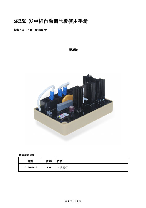
SE350发电机自动调压板使用手册版本 1.0日期:2015/06/27
SE350
版本历史记录:
日期版本内容
2015-06-27 1.0首次发行
目录
2.技术参数 (3)
3.尺寸图 (4)
4.接线 (5)
3.1.励磁场接线“+、一” (5)
3.2.检测&电源输入“3、4” (5)
3.3.外接电压调节器“6、7” (5)
3.4.低频保护一频率选择“50/60” (5)
5.操作说明 (6)
6.测试图: (8)
1.技术参数
项目参数说明
电源检测输入电压85-135VAC/190-r240VAC
单相频率50/60Hz以跨接线设定
电压选择指拨开关选择120/240VAC
输出电压120VAC输入时最大36VDC
240VAC输入时最大73VDC
电流连续4A
非连续为10秒内7A(52/105VDC)
电阻最小15Ohm最大100Ohm
电压建立在AV R输入端子需剩磁电压5VAC以上,25Hz EMI抑制内建与突波吸收器与滤波器
调压精度<士1%(发动机转速变动在4%内)
外部电压调节用1K Ohms1Watt电位器时为士5%
用2K Ohms1Watt电位器时为士10%
消耗功率最大8Watt
低频保护50Hz系统转折点为45-51Hz
60Hz系统转折点为54-61Hz
(*拐点值为出厂设定值)
尺寸99.5mm L*67mm W*47.5mm H
重量0.3KG
2.尺寸图
图一
3.接线
3.1.励磁场接线“+、一”
(1)将调压板上注“F+”之引线连接于励磁机磁场“+”,将注“F-”引线连接至磁场“一”。
注:励磁机磁场直流电阻为15-100Ω。
(2)如果磁场电阻小于15Ω且在发电机全载时,磁场电压小于70V DC时可串接一适当瓦数
(W)的电阻,使磁场总电阻为15一100Ω。
3.2.检测&电源输入“3、4”
调压板上注“3、4”引线接至发电机组绕组,可由电压选择开关选择120或240VAC系统。
3.3.外接电压调节器“6、7”
(1)调压板内部提供一发电机电压粗调预设旋钮(VOLT),顺时针方向增加。
(2)出厂预设6、7短路,如须外接电压调节时可将6、7开路、在两端并一电位器(1KΩ
1Watt),可调范围约为粗调±5%。
3.4.低频保护一频率选择“50/60”
(1)50Hz使用时,出厂拐点值为47Hz,可调范围为45一51Hz,须将端子50跨接。
(2)60Hz使用时,出厂拐点值为57Hz,可调范围为54一61Hz,须将端子60跨接。
4.操作说明
在发电机启动前请如下步骤确认
4.1.起始预设
A.确认调压板规格是否符合系统需求?
B.确认调压板接线是否如下:
(1)如无外接电压调节旋钮时,6、7须跨接;
(2)发电机为50Hz时须将50Hz端子跨接,60Hz时60Hz端子跨接。
C.若确认励磁场输出+、-与磁场电源3、4是否正确?依所需额定电压(如图三~五)。
D.电压调节旋钮"VOLT”反时针方向调到底,外部电压调节旋钮调至中央,稳定调节“STAB”
调至中央。
4.2.发电机组启动
A.确认已完成起始预设的结线方式。
✧注!!调压板所读取AC电压均为平均值(Average)。
B.启动发电机组且调节至额定转速,此时发电机所产生之电压值应小于额定电压。
如不是
请重新确认起始预设。
C.缓慢调节电压调节旋钮“VOLT”至额定电压,此时发电机电压可能产生不稳定的摆动,
顺时针方向调节稳定旋钮"STAB",以降低摆幅直至稳定。
但过度的调节将会在负载变动时产生短暂的摆动。
✧建议!!反时针方向调节称定旋钮,当电压开始不穗时再顺时针方向转1/6圈。
D.如果使用外部电压调节作电压微调时(目前电压值应等于额定电压值),如果无法调至额
定值或无法调节时,请检查电位器是否短路、阻值太小或发电机转速太低(低频电路动作中),如剩磁电压小于5VAC时,请依“励磁场初期电压诱起,,方式进行励磁场。
E.确定发电机与调压板均在正常范围内操作。
F.空载至全载调压精度小于±1%如果调节率不在此范围内,请确认以下:
(1)发电机转速不足(低于低频保护拐點值);
(2)发电机输出波形严重畸变;
(3)电容性负载比例过大.(功因超前);
(4)更换调压板重试。
4.3.磁场初期电压诱起
当发电机组第一次使用或剩磁消失或磁场连接线+、一两极反向时,由于剩磁电压小于5VAC,不足以使调压板建立电压,请停止发电机运转且依如下操作。
A.停止发电机组运转,拆离调压板磁场连接线F+,F-使用一组直流电源(6-12VDC)正极接
到发电机磁场+,负极串一电阻(限流)3~5Ω20Watt(可用电瓶作为直流电源)。
B.如上述通电流时间约三秒即可。
C.拆除调压板上的3、4连接线,启动发电机(至额定转速)检测剩磁电压(发电机端3、4)
是否大于5VAC,如是,恢复所有调压板接线且启重新起动发电机即可顺利建立电压。
如剩磁仍小于5VAC请重做如A~B。
D.如剩磁电压大于5VAC,但调压板仍无法建立电压时,请更换另一调压板。
警告:过度励磁可能损坏AVR或发电机励磁线圈。
4.4.维护
请定期维护调压板、保持表面清洁、避免油渍水份附着表面。
所有连接线、端子、外接电位器需牢固且无腐蚀。
4.5.测试电路
A.将AVR拆离发电机且(如图二)接线。
B.3、4接一220VAC电源且在AVR上选择该电源之频率。
C.接一钨丝灯泡(50-100W)于F+与F-之间。
D.可选用一只1KΩ电位器置于6、7之间,若无须外部调节可将6、7跨接。
E.将VOLT旋钮反时针调节到底,STAB至中央,U/F反时针调节。
F.加入电源,此时灯泡应保持熄灭状态。
G.顺时针方向缓慢调节VOLT,此时灯泡应由灭渐亮,反方向调节时灯泡应由亮渐灭。
H.将STAB顺时针调节到底,再如上G调节VOLT时灯泡亮灭速度会变为缓慢,反时针调节
STAB到底灯泡亮灭速度会变快。
I.缓慢调节VOLT使灯泡由灭转亮再顺时针调节U/F到底,此时灯泡应由亮转灭.
J.所有测试灯泡均须为平滑亮灭。
5.测试图:
图二AVR测试电路图三220VAC接线图
图四图五。