日立(HITACHI)L200变频器说明书
- 格式:pdf
- 大小:2.11 MB
- 文档页数:3
日立变频调速器PID控制用户指南1. 概述 32. SJ100/L100/L300P/SJ300系列变频器PID控制 32-1 PID控制 3(1) P: 比例控制 4(2) I : 积分控制 5(3) D: 微分控制 5(4) PID控制 5 2-2 PID增益调整 & 控制特性 6 3.应用 7 3-1 结构 & 参数 7(1) 控制模式 7(2) 参数 7(3) 微分计算 8(4) 目标值输入 8(5) 反馈输入 & PID控制范围设定 8(6) 比例变换 93-2 PID控制参数综述 93-3 设定举例 11(1) 频率控制模式下的参数设定 11(2) PID设定 (目标值&设定值) 11(3) 比例变换常数设定 12(4) 由数字输入信号设定目标值 12(5) PID模式选择 123-4 各增益调整的示例( Kp&Ti) 13(1) 比例增益调整(Kp) 13(2) 积分时间调整(Ti) & Kp的再次调整 133-5 注意事项 13 4. 实际应用示例 144-1 恒流量控制 14 4-2 恒温控制 15SJ100/L100/SJ300/L300P 系列变频器具有内置PID 控制功能.可用于风机&泵类应用的恒流量控制等,PID 控制具有如下特点:• 目标值不但可通过数字操作器给定而且可通过外部数字信号给定(多段速方式:可设定16个不同的目标值).另外,也可通过模拟量输入信号设定(0~10V,4~20mA).• 反馈信号可通过模拟电压输入 ( 0~10V)或模拟电流输入信号(4~20mA)给定. • 对于反馈信号,控制有效范围可单独定义。
例如0~5V,4~20mA 或其它. • 通过使用比例变换功能,可显示/设定气体流量,水的流量或温度等反馈值/目标值的实际值(物理量).请阅读本指南以正确使用L100/SJ100/L300P/SJ300具有的方便的PID 功能。
Hitachi ’s L300P Series Variable FreI ncreased Energy Savings for Your AUTOMA TIC ENERG Y-SA VINGFUNCTIONWith its Automatic Energy-saving Function, the L300P delivers “real-time” energy-saving operation for your fan and pump applications. The function insures that motor operates at minimum current in response to the torque required by the load.ENHANCED INPUT/OUTPUT TERMINALSThree relay output terminals are provided as standard for flexible interface to external control systems.ANALOG OUTPUT MONITORIn addition to PWM monitor(FM), programmable analog output monitors are also available for both voltage(0-10VDC) and current(4-20mA) at AM and AMI terminals of the L300P.INTELLIGENT INPUT/OUTPUT TERMINAL SYSTEMThe L300P features an intelligent control terminal system, which allows necessary drive I/O functions to be freely programmed. Input terminals can be selected for either sink or source type logic.EASY- TO-USE OPERA TOR PANELOutput frequency Output current Rotation directionProcess variable, PID feedback Intelligent input terminal statusINTELLIGENT RELAY OUTPUTSNO contact X 2 NO-NC contact X 1AL212C 12A 11C 11A AL0AL1L300P's digital operator panel supports various monitoring functions.Cumulative power-on time Trip event Trip history Warning codeIntelligent output terminal status Scaled output frequency Output voltage PowerCumulative RUN timeExample of Energy Savings (Fan)Operation by Inlet vane and damperOperation by v/f controlOperation by AutomaticEnergy-saving FunctionAmount of energy t o be savedP o w e r C o n s u m p t i o nFrequency[Sink type logic]CM1FWL300PP24FWL300P[Source type logic]Upper SystemUpper System+Power SupplyWIDE RANGE OF APPLICATION SPECIFIC FUNCTIONSquency Drive DeliversFan and Pump Applications!CONTENTSHitachiInverterL300PEase ofOperationGlobalStandardsHigh-performanceEasyMaintenanceCompactSizeFEATURESSTANDARD SPECIFICATIONSDIMENSIONSOPERA TION and PROGRAMMINGFUNCTION LISTTERMINALSPROTECTIVE FUNCTIONSCONNECTING DIAGRAMCONNECTING TO PLCWIRING and ACCESSORIESACCESSORIESFOR COMPACT PANELTORQUE CHARACTERISTICS, DERATING DATAFOR CORRECT OPERATION1 - 45 - 78 - 111213 - 1617 - 181920 - 21222324 - 26272829 - 30 FOR OPTIMAL OPERATIONHitachi variable frequencydrives (inverters) in thisbrochure are produced at thefactory registered under theISO 14001 standard forenvironmental managementsystem and the ISO 9001standard for inverter qualitymanagement system.ISO 14001EC97J1095ISO 9001JQA-1153Eliminates control rewiring when field replacing the L300P.The L300P’s compact size helps economize panel space.Installation area is reduced by approximately 30% from that of our previous series.(Comparison of 11kW (15HP))RS485 is provided as standard for ASCII serial communication.Optional PC drive configuration software which runs on Windows ® Operating System.Output frequency can be controlled by the integral potentiometer provided as standard on the OPE-SR.The OPE-SR can be removed for remote control, and has an easy-to-see 4-digit display and LEDs to indicate the unit being monitored (i.e. frequency, amps, power, etc.). A multilingual operator (English, French, German, Italian, Spanish, and Portuguese) with copy function (SRW-0EX) and a digital operator without potentiometer (OPE-S) are also available as options.EASY-REMOV ABLE COOLING F ANAND DC BUS CAPACITORREMOV ABLE CONTROL CIRCUIT TERMINALSEASE OF OPERA TION WITH DIGITAL OPERATOR (OPE-SR)USER SELECTION OF COMMAND FUNCTIONS (“Quick Menu”)BUIL T-IN RS485PROGRAMMING SOFTWARECooling fan(s) and DC bus capaci-tors can be easily changed in the field. A fan ON/OFF function can be activated to provide longer cooling fan life.Control Circuit TerminalsEMI filters to meet European EMC (EN61800-3, EN55011) and low-voltage directive (EN50178) are available for system conformance.CE, UL, c-UL, C-Tick approvals.Standard enclosure protection for the L300P is IP20 (NEMA1*). For IP54 (NEMA12), please contact Hitachi sales office.MODEL NAME INDICATIONSeries NameVersion numberU:UL version for North America E:CE version for EuropeL :3-phase 200V Class H:3-phase 400V ClassF:With Digital OperatorPower SourceApplicable Motor CapacityL300P -015 L F U 2EMI FIL TERHARMONICS MITIGATIONCONFORMITY TO GLOBAL STANDARDSNETWORK COMPATIBILITYThe L300P can communicate with DeviceNet™, PROFIBUS ®, LONWORKS ®, Modbus ® RTU *1, and Ethernet™*2 with communication options.*1, *2: Being planned*NEMA 1 applies up to 30kW. An optional wire-entry conduit box is required for 37kW to 75kW models to meet NEMA 1 rating.Disturbance voltage of the main circuit power supply and of the control circuit power supply has been improved by approximately 15dB( V) and 20dB( V) respectively compared to our previous model(J300), resulting in significant reductions to noise interference with sensors and other peripheral devices.REDUCED NOISE FROM MAIN CIRCUIT POWER SUPPL Y ANDCONTROL CIRCUIT POWER SUPPL YCONTROL OF VOLTAGE OF MICRO SERGE11(15)L300P-110LFU2L300P-110HFU2/E215(20)L300P-150LFU2L300P-150HFU2/E218.5(25)L300P-185LFU2L300P-185HFU2/E222(30)L300P-220LFU2L300P-220HFU2/E230(40)L300P-300LFU2L300P-300HFU2/E2MODEL CONFIGURATIONApplicable Motor Capacity in kW (HP)3-phase 200V class3-phase 400V class1.5(2)L300P-015LFU2L300P-015HFU2/E22.2(3)L300P-022LFU2L300P-022HFU2/E23.7(5)L300P-037LFU2L300P-040HFU2/E25.5(7.5)L300P-055LFU2L300P-055HFU2/E27.5(10)L300P-075LFU2L300P-075HFU2/E237(50)L300P-370LFU2L300P-370HFU2/E245(60)L300P-450LFU2L300P-450HFU2/E255(75)75(100)L300P-750HFU2/E290(125)L300P-900HFU2/E2110(150)L300P-1100HFU2/E2132(175)L300P-1320HFU2/E2L300P-550LFU2L300P-550HFU2/E2L300P-750LFU2IMPROVEMENT OF ENVIRONMENTThe printed circuit board inside an inverter is varnish coating specification as standard.204060801000.2.3.5.71571030203J300-055LFU L300P-055LFU240607080901000.2.3.5.7157102030Frequency(MHz)Frequency(MHz)J300 seriesJ300 seriesL300P seriesL300P seriesJ300-220LFU Disturbance voltage of the main circuit power supply(It does not comply with European EMC directive. To meet the EMC directive, please use an EMI filter.)Disturbance voltage of the control circuit power supply (Disturbance voltage of terminal L or CM1)D i s t u r b a n c e v o l t a g e [d B (µV )]D i s t u r b a n c e v o l t a g e [d B (µV )]L300P-220LFU2Terminals for the connection of a DC Reactor are provid-ed as standard for harmonics suppression.Suppressing the motor terminal voltage less than 2xE [V]by improving the control method of PWM output.Input voltage:400VAC(In the case)Motor terminal voltage:1,131V(400V X 2X 2STANDARD SPECIFICATIONSSTANDARD SPECIFICATIONS**DIMENSIONSOPERATION and PROGRAMMINGPress up or down to sequence through parameters and functions shown on the display, and increment/decrement values.Press to set or monitor a parameter value.L300P Series can be easily operated with the digital operator (OPE-SR) provided as standard. The Digital operator can also be detached and used for remote-control. A multilingual (English, French, German Italian, Spanish, and Portuguese) operator with copy function (SRW-0EX) or a digital operator without potentiometer(OPE-S) is also available as an option.(For US version, OPE-SRE (English overlay with potentiometer) is provided as standard.)FUNCTION LIST(*1) 90kW and overTerminal ArrangementScrew Diameter and Terminal WidthTerminal Arrangement015-055 LFU2, HFU2, HFE2Screw diameter M3, Terminal width 6.4mmTERMINALSControl Circuit TerminalsTerminal Description110-150HFE2, 075-150HFU2/LFU2*For ground screw of 200, 300, 450, 550 LFU2, M6 is used. For 900-1320HFE/HFU2, M8 is used.Terminal Description [ ]: Default setting (CE/UL)PROTECTIVE FUNCTIONS(*1)(*2)How to access the details about the present faultCONNECTING DIAGRAM SOURCE TYPE LOGICSINK TYPE LOGICCONNECTING TO PLCWIRING and ACCESSORIESOPERATORREMOTE OPERATOR SRW-0EX(Optional )ACCESSORIES*OPE-SRE: English overlayEXPANSION CARDUp to two expansion cards can be installed inside the L300P.FOR COMPACT PANELHeat accumulation in the panel can be reduced by arranging inverter heat sink outside.TORQUE CHARACTERISTICSDERATING DATAFOR CORRECT OPERATIONApplication to Motors[Application to general-purpose motors][Installation location and operating environment]CALL NOW 800-985-6929 Email:*********************** [Main power supply]High-frequency Noise and Leakage Current(1) High-frequency components are included in the input/output of the inverter main circuit, and they may cause interference in a transmitter, radio, or sensorif used near the inverter. The interference can be minimized by attaching noise filters (option) in the inverter circuitry.(2) The switching action of an inverter causes an increase in leakage current. Be sure to ground the inverter and the motor.Lifetime of Primary PartsPrecaution for Correct UsageBefore use, be sure to read through the Instruction Manual to insure proper use of the inverter.Note that the inverter requires electrical wiring; a trained specialist should carry out the wiring.The inverter in this catalog is designed for general industrial applications. For special applications in fields such as aircraft, outer space, nuclearpower, electrical power, transport vehicles, clinics, and underwater equipment, please consult with us in advance.For application in a facility where human life is involved or serious losses may occur, make sure to provide safety devices to avoid a serious accident.The inverter is intended for use with a three-phase AC motor. For use with a load other than this, please consult with us.Information in this brochure is subject to change without notice.CALL NOW 800-985-6929 Email:***********************。
L300P200/400VNB601BCXCL300P()----WARNINGCAUTIONWARNING CAUTION CAUTION CAUTION( WARNING) NOTEHAZARDOUS HIGH VOLTAGEiWARNING:WARNING:150%WARNING:WARNING: WARNING:CAUTION: CAUTION:L300PCAUTION:L300PCAUTION: CAUTION:221 2iiL300P89/336/EECEMCWARNING:1.L300P (1) (2) (3) (4)±10% ±3% ±4% THD 10%2. (1) 3. (1) (2) (3) 4. (1) (2) (3) 10 40 20 90 RH( ) 5.9m/S2(0.6G)10-55Hz(L300P-110L/HF-300L/HF) 2.94m/S2(0.3G)10-55Hz(L300P-370L/HF-550L/ HF,750HF~1320HF) 1000m( ) 20m 3kHz EMC L300P(4)iii1 2 3 4 5CB601CX NB601AX NB601BCX NB601BCXA NB601BCXB2000 2000 2001 2002 20048 10 11 11 4NB601CX NB601BCX NB601BCXA NB601BCXB NB601BCXCiv1 WARNINGp.2-1p.2-5p.2-5p.2-5 60/75deg.Cu p.2-5 5,000rms 240 5,000rms 480V UL p.2-5 p.2-12 p.2-5vp.2-1p.2-1p.2-1p.2-1 (4 ) p.2-1p.2-1p.2-1p.2-5p.2-5 PD P N p.2-5vi!p.2-1p.2-5p.2-52.!p.3-4 p.3-4vii○○○○○○○○○○○○○○○○○○○○○○○○○○○○○○○○○○○○○○○○○○○○○○○○○○○○○○○○○○○○○○○○○○○○○○○○○○○○○○○○○○○○○○○○○○○○○○○○○○○○○○○○○○○○○○○○○○○○○○○○○○○○○○○○○○○○○○○○○○○○○○○○○○○○○○○○○○○○○○○○○○○○○○○○○○○○○○○○○○○○○○○○○○○○○○○○○○○○○○○○○○○○○○○○○○○○○○○○○○○○○○○○○○○○○○○○○○○○○○○○○○○○○○○○○○○○○○○○○○○○○○○○○○○○○○○○○○○○○○○○○○○○○○○○○○○○○○○○○○○○○○○○○○○○○○○○○○○○○○○○○○○○○○○○○○○○○○○○○○○○○○○○○○○○○○○○○○○○○○○○○○○○○○11.1○○○○○○○○○○○○○○○○○○○○○○○○○○○○○○○○○○○○○○○1.1.1 1.1.2○○○○○○○○○○○○○○○○○○○○○○○○○○○○○○○1.2○○○○○○○○○○○○○○○○○○○○○○○○○○○○○○1.2.1 1.2.2○○○○○○○○○○○○○○○○○○○○○○○○○○○○○○○○1.3○○○○○○○○○○○○○○○○○○○○○○○○○○○○○○○○○○○○○○○○○1.3.1○○○○○○○○○○○○○○○○○○○○○○○○○○○○22.1○○○○○○○○○○○○○○○○○○○○○○○○○○○○○○○○○○○○○○○○○○2.1.1 2.1.2○○○○○○○○○○○○○○○○○○○○○○○○○○○○○○○○○○○○○2.2○○○○○○○○○○○○○○○○○○○○○○○○○○○○○○○○○○○○○○○○○2.2.1 2.2.2 2.2.3○○○○○○○○○○○○○○○○○○○○○○○○○○○○○○○○○33.1 3.2○○○○○○○○○○○○○○○○○○○○○○○○○○○○○○○○○○○○○○○○○○44.1 4.2 4.3OPE-SR○○○○○○○○○○○○○○○○○○○○○○○○○○○○○○○4.3.1 4.3.2○○○○○○○○○○○○○○○○○○○○○○○○○○○○○○○○○4.4○○○○○○○○○○○○○○○○○○○○○○○○○○○○○○○○○○○○4.4.1 4.4.2 4.4.3○○○○○○○○○○○○○○○○○○○○○○○viii○ ○ ○ ○ ○ ○ ○ ○ ○ ○ ○ ○ ○ ○ ○ ○ ○ ○ ○ ○ ○ ○ ○ ○ ○ ○4-1 4-5 4-10 4-10 4-14 4-75 4-75 4-77 4-78 3-1 3-2 2-1 2-2 2-4 2-5 2-6 2-8 2-13 1-1 1-1 1-1 1-2 1-2 1-2 1-3 1-3○○○○○○○○○○○○○○○○○○○○○○○○○○○○○○○○○○○○○○○○○○○○○○○○○○○○○○○○○○○○○○○○○○○○○○○○○○○○○○○○○○○○○○○○○○○○○○○○○○○○○○○○○○○○○○○○○○○○○○○○○○○○○○○○○○○○○○○○○○○○○○○○○○○○○○○○○○○○○○○○○○○○○○○○○○○○○○○○○○○○○○○○○○○○○○○○○○○○○○○○○○○○○○○○○○○○○○○○○○○○○○○○○○○○○○○○○○○○○○○○○○55.1/○○○○○○○○○○○○○○○○○○○○○○○○○○○○○○○○○5.1.1 5.1.2 5.1.3○○○○○○○○○○○○○○○○○○○○○○○○○○○○○○○○○○○5.2 5.3 5.4 5.5 5.6○○○○○○○○○○○○○○○○○○○○○○○○○○○○○○○○○66.1 6.2○○○○○○○○○○○○○○○○○○○○○○○ix○ ○ ○ ○ ○ ○ ○ ○ ○ ○ ○ ○ ○ ○ ○ ○ ○ ○ ○ ○ ○ ○ ○ ○ ○ ○ ○ ○ ○ ○ ○ ○ ○ ○6-1 6-2 5-1 5-1 5-1 5-1 5-2 5-3 5-3 5-4 5-51.1 1.1.11 2 31-1Model : L300-110HFE HP / kW : 20/15 V 1 Ph Input/Entree : 50Hz, 60Hz A 25 A 50Hz, 60Hz 400-480 V 3 Ph Output/Sortie: 0.1 - 400Hz 400-480 V 3 Ph 23 A Date : 0303 MFG No. 3 3 A T 1 2 3 4 5 9 0 0 1 Hitachi Industrial Equipment M A D E I N JA PA N N E 1 6 9 8 9 - 2 9System Co.,Ltd.1-211.2L300P1-11.21.2.11 2 3 4MFG.No1.2.21 2 3 41-21.31.3.11-32.12-12.1.112 1501 211~75KW 11~75KW 11~75KW 18.5~75KW 90~132KW10cm 10cm 10cm 22cm 30cm90~132KW 90~132KW30cm 30cm1)5cm5cm2)3 -10 504 20 902-256789kW 70% 100% 100% W W 11 435 300 94.5 15 575 800 94.6 18.5 698 975 94.7 22 820 1150 94.8 30 1100 550 94.9 37 1345 1900 94.9 45 1625 2300 94.9 55 1975 2800 94.9 75 2675 3800 95.2 90 3375 4800 95.2 110 3900 5550 95.2 132 **** **** 95.22-32.1.2 122-42.2PDPN2-52.2.1R200-240V+-10%(50, 60Hz+-5%) 380-480V+-10%(50, 60Hz+-5%)POWER ALARM RAN PRGHz V A % kWU V WS T R T (J51) RO TO P24RUNSTOP/RESETFUNC12P PD RB NBRD 15kWFWALO AL15 4AL211A53 1 DC24V 11C 12ACM1FMPLC FM SP TH H SN RP SN10k ohm 100 ohm 10k ohm12CRS485DC 0-10VDC 0-10V(12 位) DC -10 -+10V(12 位) DC 4-20mA(12 位)O O2 O1 LDC10V1AM0-10V(8 位)AM2AMIAMI4-20mA(8 位)G2 -61 R S T (L1 L2 L3) U V W (T1 T2 T3) PD P (+1 +) P RB (+ RB) P N (+ -) G (2).RG.DC(DCL-XX)PDP(BRD-XX)(15kW)L H O O2 ( )(O,OI,O2) +10V 0 10V , 10V +10V ,,AM,AMI 20mA 10V. , A014 O OI 10K 10K 20mA , 20mA10VOI AM AMI ( (( ))4-20mA, 20mA ON ,.AT100 24mA 2mA, ) , ,,, 2501.2mA FM P24 CM1 FW ,1-5 ( ) DC24V . , 3.6k 100mA .,TH,FMPLC FW1 2 3 4 5(PLCP24-PLC: FW 33, CM1-PLC:27V,ON 5 ,,OFF 1 11 5ON 3V AC25V DC30V4.7k 18V OFF11A 11C 12A 12C AL1 AL2 AL0 TH11 11 12 12 , C125A R 1A L 5A R 1A L DC1V 1mA/AL1 AL0 AC250V 2A 0.2 AL2 AL0 AC250V 2A 0. 2A AC100VR L R L 10mATH ,CM1 , CMI,10k 100mW2-72.2.2 11R S T R ST2U V W20 400V EMC3DCL PD P DCLPD DCLP DCL4 15kW 5PRB BRDBRD2-85 15kW BRDPN BRD P N P N5 6 G2-92R (L1) PD (+1)S (L2) P (+)T (L3) N (-)U (T1) RBV (T2) GW (T3) GRoToL300P-110 150-LF/HFE Ro-To M4 M6L300P-185LF L300P-185-370HFERo ToRo-ToM4 M6GR (L1)S (L2)T (L3)PD (+1)P (+)N (-)U (T1)V (T2)W (T3)GL300P-370LF/HFE L300P-450,550HFE,750HFE Ro-To M4 M6L300P-220-300LFRo ToRo-ToM4 M6 M8R (L1)S (L2)T (L3)PD (+1)P (+)N (-)U (T1)V (T2)W (T3)L300P-550LF Ro-To M4 M6 M8RoToL300P-750 LF L300P-900~1320HFE Ro,To: M4 : M8 : M10R (L1)S (L2)T (L3)PD (+1)P (+)N (-)U (T1)V (T2)W (T3)2-10(3) 4 1: 2: 3: 4: . . 20 , 0.75mm2ELB,. (ELB)., . (mA) 100 300 5: CV 6: IV 8 50 100 , 8 . . 100 , CV( , (, )(AL---*) )(ZL-*) (JF-***) .3 , .500kVA, ,RST PD P. . .R0 T0 U VRB N W(CFI-*) (DCL-*-**) (ACF-C*) . . .( ( , (ACL-*-**) ZCL-***) , ) . . . LCR ( 10 ) . .IM2-11PPB(kW11 15 18.5 22 30 37 45 55 75 11 15 18.5 22 30 37 45 55 75 90 L300P-110LFU L300P-150LFU L300P-185LFU L300P-220LFU L300P-300LFU L300P-370LF UR, S, T, U, V, W, P, PD,N14 mm 5.5mm 22 mm2 5.5mm2 30 mm2 2 38 mm 60 mm2 100 mm2 2) 100 mm2 2) 150 mm2 2) 150 mm2 2) 5.5 mm2 5.5 mm2 8 mm2 5.5 mm2 14 mm2 14 mm2 22 mm2 38 mm2 2 38 mm 60 mm2 100 mm2 2) 100 mm2 2) 150 mm2 2) 2 2 2N.mM6 M6 M6 M8 M8 M8 M10 M10 M10 14-6 2.5 22-6 2.5 38-6 2.5 38-8 6 60-8 6 100-8 6 100-10 150-10 6 6 10 2.5 2.5 2.5 2.5 2.5 2.5 2.5 6 6 6 10 10ELBMg200VRX225B(75A) RX225B(100A) RX225B(100A) RX225B(150A) RX225B(200A) RX225B(225A) RX225B(225A) RX400B(350A) RX400B(350A) EX50C(50A) EX50C(60A) EX60B(60A) EX100(75A) RX100(100A) RX100(100A) RX225B(150A) RX225B(175A) RX225B(225A) RX225B(225A) RX400B(225A) RX400B(350A)H50 H65 H80 H100 H125 H150 H200 H250 H300 H25 H35 H50 H50 H65 H80 H100 H125 H150 H150 H250 H300(38 L300P-450LFU (38 L300P-550LFU (60 L300P-750LFU (60 L300P-110HFE/U L300P-150HFE/U L300P-185HFE/U L300P-220HFE/U L300P-300HFE/U L300P-370HFE/U L300P-450HFE/U L300P-550HFE/U L300P-750HFE/U (38 L300P-900HFE/U (38 110 L300P-1100HFE/U 132 L300P-1320HFE/U (60 80150-10 (60-10) M6 5.5-6 M6 8-6 M6 14-6 M6 14-6 M6 22-6 M6 38-6 M8 38-86 M8 60-8 M8 100-8 (38-8) M10 100-10 (38-10) M10 150-10 (60-10) M10 80-10400VRo ACL3To Ro EMI To ACL EMI1ON200~240V 10% (50/60Hz (DC282~339V)5%) 2 J51380~480V 10% (50/60Hz (DC537~678V)5%)J512-122.2.3 1 1 CM1 2 3 4 5 6 L20 CVD-E20VXRCD-A90 TH CM1TH FW8 CM1 6PLC CM1 77 8 9FM H L P2424V CM11H L OO2 OIAM AMIFM P24TH PLCFW CM15 12C4 12A3 11C2 11A1 AL0AL1 AL2M3 2 PLC PLC CM1 P242-134S 跳线P24 PLC CM1 FW DC24VSP24 PLC DC24V CM1 FW8 8 DC24V COM TYR48 输出模块 TYR48 输出模块 COM变频器变频器COMP24 DC24V PLCCOM DC24VP24 PLC M1C DC24V跳线CM1FWFW88SSYTS48 输出模块变频器YTS48 输出模块变频器2-143.11 FW RV ON[1] [2] DC0 10V DC-10V +10V 4 20mA2FWRV[1]33-14-1 1ELB R S T R S T FW 5 (RV) 1 FM TH (OPE-4MJ2) (OPE-8MJ2) H O CM1 PLC P24 H O OI O2 AM AMI L G D U V W PD P RB N AL0 AL1 AL2 11A 11C 12A 12C SP SN RP SNL[1] [2] [3] A001 A001 [4] A002 A002 [5] d001 d003 [6] [FW] [O] [7] [FW] [P24]3-2ELB FUNC 01 STRPOWERFUNC 01 STRFUNC FUNC[P24] [L]2ELB R S T R S T FW 5 1 FM TH CM1 PLC P24 H O OI O2 AM AMI L G D U V W PD P RB N AL0 AL1 AL2 11A 11C 12A 12C SP SN RP SN[1] [2] [3] A001 A001 [4] A002 A002 FUNC 02 STR FUNC 02 STR ELB ON POWER3-3[5] F001 F001 [6] F004 STR [7] d001 d003 ( [8] ( [9] ( RUN RUN STOP/RESET 0 RUN ) ) FUNC FUNC ) FUNC 00 F004 00 01 01 FUNC STR3-44.1(OPE-SR)(OPE-SR)L300P 1.LEDHITACHIRUN() ) STR( )FUNC( 1( )2( /)RUN/STOP RUN / FUNC STR /4-12 (1)[1] (0.00)[5] (d001)[2]FUNC66[2] ([4] ( d001)A---)FUN.FUNA b C H P U6 [3] ( 186(d002)(1)F001)18 1): 4-2 (3)(2) ([1])[5] A---(1)A---FUNC [4] [2] ( A002)FUNCSTRSTR FUNC [3]02(PRG) 4-3(01)(3) d001[1] ( d001) (A029A029) STR [6]9 9 ( [2] [5] 9 2 ) A" A029"d" 2 1 STR A021(A001)"A" STR STR A [3] 3 STR [4] 222 20 3 0 3 0 4-4 STR 2 04.2-FE/FU d001 d002 d003 d004 d005 0.00-99.99/100.0-400.0Hz 0.00-999.9A F( )/o( )/r( ) 0.00-99.99/100.0-999.9/1000.-9999. /1000-9999/ 100- 999(10000-99900)( ) FW, 5,4 2 3 1 ON OFFPID4-10 4-10 4-10 4-104-11d006()12 AL OFF11ON4-11d007 d013 d014 d016 d017 d080 d081 d082 d083 d084 d085 d086 d090 F001 F002 F202 F003 F203 F0041 20.00-99.99/100.0-999.9/1000.-9999./1000-3996 0.0-600.0V 0.0-999.9kW ( ) 0.-9999./1000-9999/ 100- 999(10000-99900)hr 0.-9999./1000-9999/ 100- 999(10000-99900)hr 0.-9999./1000-6553(10000-65530)4-12 4-12 4-12 4-13 4-13 4-13 4-13 4-13 4-13 4-13 4-13 4-13 4-78 4-14 4-16 4-16 4-16 4-16 4-141 2 3 4 5 6 0.0, ( 2 0.01-99.99/100.0-999.9/1000.-3600.sec (1) 1 2 (1) 0.01-99.99/100.0-999.9/1000.-3600.sec 0.01-99.99/100.0-999.9/1000.-3600.sec 0.01-99.99/100.0-999.9/1000.-3600.sec 00( )/01( )b031 STR 10 STR(Hz)(A)(hr)1 2) 0.00Hz 30.00s 30.00s 30.00s 30.00s 004-5-FE/FU A001 A002 A003 A203 A004 A204 A005 A006 A011 A012 A013 A014 A015 A016 A019 A020 A220 A021 A022 A023 A024 A025 A026 A027 A028 A029 A030 A031 A032 A033 A034 A035 A038 A039 00( 01( 2 2 AT O2 O O O O O O,O1,O2 (0) 2 1 2 3 4 5 6 7 8 9 10 11 12 13 14 15 (0) )/02( )/03(RS485)/04( (1))/05( (2)) )/03(RS485)/04( (1))/05( (2)) 30.00Hz30.00Hz- 2 30.00-400.0Hz 30.00-400.0Hz 00( AT O O1)/01( AT O O2) 00( )/01(O,O1 )[ ] 02(O,O1 )[ ] 0.00-99.99/100.0-400.0Hz 0.00-99.99/100.0-400.0Hz 0.-100.0(%) 0.-100.0(%) 00( )/01(0Hz) 1.-30 00( :4 16 )/01( :5 6 ) 0.00, (Hz) 0.00, 2 0.00, 0.00, 0.00, 0.00, 0.00, 0.00, 0.00, 0.00, 0.00, 0.00, 0.00, 0.00, 0.00, 0.00, 0.00, 0.00, 9.99Hz 00( / )/01( / )/02( / )/ 03( / )/ 04( / )/ 05( / ) 00( )/01( ) 00( )/01( ) 0.0-20.0% 0.0-20.0% 0.0-50.0% 0.0-50.0% 00(VC)/01(VP1.7 )/02(V/f ) 00(VC)/01(VP1.7 )/02(V/f ) 20.0-100.0 00( )/01( ) 0.00-60.00Hz 0.0-5.0sec 0.0-100.0% 0.0-60.0sec 00( )/01( ) 0.-70.0(%) 0.00-60.0sec 0.5-12kHz( )(0.5~8) )/01( )/02( 01 01 50/60 50/60 50/60 50/60 00 00 0.00 0.00 0. 100. 01 8. 00 0.00 0.00 0.00 0.00 0.00 0.00 0.00 0.00 0.00 0.00 0.00 0.00 0.00 0.00 0.00 0.00 0.00 1.00 4-14 4-15 4-17 4-17 4-18 4-18 4-19 4-19 4-20 4-20 4-20 4-20 4-20 4-21 4-43 4-43 4-43 4-43 4-43 4-43 4-43 4-43 4-43 4-43 4-43 4-43 4-43 4-43 4-43 4-43 4-43 4-43 4-44004-44A041 A241 A042 A242 A043 A243 A044 A244 A045 A051 A052 A053 A054 A055 A056 A057 A058 A0592 2 2 V/f 2V/f(/)00 00 1.0 1.0 5.0 5.0 00 00 100.0 00 0.50 0.0 0.0 0.0 01 0. 0.0 3.04-24 4-24 4-24 4-24 4-22 4-22 4-25 4-25 4-24 4-25 4-25 4-25 4-25 4-25 4-25 4-25 4-25 4-25V/f4-6AVRA061 A261 A062 A262 A063 A064 A065 A066 A067 A068 A069 A070 A071 A072 A073 A074 A075 A076 A081 A082 A085 A086 A092 A292 A093 A293 A094 A294 A095 A295 A096 A296 A097 A098 A101 A102 A103 A104 A105 A111 A112 A113 A114 A131 A132 b001 b002 b003 b004 b005 b006 b007 b012 b212 b013 b213 b015 b016 b017 b018 b019 b0200.00, 2 2 (1) (1) (2) (2) (3) (3) 0.00, 0.00, 2 0.00-99.99/100.0-400.0Hz 0.00-10.0Hz 0.00-99.99/100.0-400.0Hz 0.00-10.0Hz 0.00-99.99/100.0-400.0Hz 0.00-10.0Hz 0.00-99.99/100.0-400.0Hz 0.0-60.0sec 00( )/01( ) 0.2-5.0 0.0-3600.0sec 0.00-100.0sec 0.01-99.99% 00( OI)/01( O) 00( ON)/01( OFF)/02( OFF) 200/215/220/230/240,380/400/415/440/460/480 00( (2 ) 2 (2) 2 / 2 (1) 2 (2) (1) 2 (2) )/01(S)/02(U )/03( U ) )/01(S)/02(U )/03( U ) 0.00-99.99/100.0-400.0Hz 0.00-99.99/100.0-400.0Hz 0.-100.% 0.-100.% 00( )/01(0Hz) -400.0-(-100.)/-99.9-0.00-99.9/100.-400.0Hz -400.0-(-100.)/-99.9-0.00-99.9/100.-400.0Hz -100.-100.% -100.-100.% 01( ) 10( ) 01( ) 10( ) 00( )/01(0Hz )/02( )/ 03( , ) 0.3-1.0sec 0.3-100.sec 00( )/01( ) 00(16 )/01( ) 00( )/01( ) 0.00-99.99/100.0-400.0Hz 0.20 -1.20 0.20 00( 00( 1 1 2 2 3 3 -1.20 )/01( )/02( )/01( )/02( 0.00-400.0Hz 0.0-1000.(A) 0.-400.Hz 0.0-1000.(A) 0.-400.Hz 0.0-1000.A ) ) 00( 00( (2) (1) (2) (1) / (2) (2) )/01( )/02( ) 0.0-100.0sec 0.01-99.99/100.0-999.9/1000.-3600.sec 0.01-99.99/100.0-999.9/1000.-3600.sec 0.01-99.99/100.0-999.9/1000.-3600.sec 0.01-99.99/100.0-999.9/1000.-3600.sec 00( 2CH )/01( ) 00( 2CH )/01( ) 0.00-99.99/100.0-400.0Hz 0.00-99.99/100.0-400.0Hz 0.00-99.99/100.0-400.0Hz 0.00-99.99/100.0-400.0Hz 0.00, 2PID PID PID PID PID PID AVR-FE/FU 0.00 0.00 0.00 0.00 0.00 0.50 0.00 0.50 0.00 0.50 0.00 0.0 00 1.0 1.0 0.0 1.0 00 02 230/400 230/460 00 50.0 15.0 15.0 15.0 15.0 00 00 0.00 0.00 0.00 0.00 00 00 0.00 0.00 20. 100. 01 0.00 0.00 -100. 100. 02 02 00 1.0 1.0 00 00 00 0.004-28 4-28 4-28 4-28 4-29 4-29 4-29 4-29 4-29 4-29 4-29 4-29 4-30 4-30 4-30 4-30 4-30 4-30 4-17 4-17 4-31 4-31 4-32 4-32 4-32 4-32 4-32 4-32 4-32 4-32 4-32 4-32 4-33 4-33 4-20 4-20 4-20 4-20 4-20 4-20 4-20 4-20 4-20 4-33 4-33 4-34 4-34 4-34 4-34 4-34 4-35 4-34 4-36 4-36/PID/OI OI OI OI OI O2 O2 O2 O2/2201 01 0. 0.0 0. 0.0 0. 0.04-36 4-36 4-37 4-37 4-37 4-37 4-37 4-374-7-FE/FU b021 b022 b023 b024 b025 b026 b031 00( )/01( 0.50 / -1.50 )/02( (A) ) 01 1.20 1.00 01 1.20 1.00 01 )/ )/ 0. 0.0 0. 0.0 0. 0.0 0. 0.0 0. 0.0 0. 0.0 0. 0.0 18 16 06 11 09 00 00 00 00 00 00)/ )/4-38 4-38 4-38 4-38 4-38 4-38 4-45(2) (2) (2)00()/01( 0.500.1-30.00(s) / )/02( -1.50 (A))b100 b101 b102 b103 b104 b105 b106 b107 b108 b109 b110 b111 b112 b113 C001 C002 C003 C004 C005 C011 C012 C013 C014 C015 C019 C021 C022 C026 C027 C028 C029 C031 C032 C036 C040 C041 C042 C043 C044 FMV/f V/f V/f V/f V/f V/f V/f V/f V/f V/f V/f V/f V/f V/f (1) (2) (3) (4) (5)(1) (1) (2) (2) (3) (3) (4) (4) (5) (5) (6) (6) (7) (7)0.10-30.00(S) SFT ON , )/01( SFT ON , b031 F001 , )/02( b031 03( b031 F001 , 10( ) 0.V/F 2(Hz) 0.0-800.0V 0.V/F 3(Hz) 0.0-800.0V 0.V/F 4(Hz) 0.0-800.0V 0.V/F 5(Hz) 0.0-800.0V 0.V/F 6(Hz) 0.0-800.0V 0.V/F 7(Hz) 0.0-800.0V 0.-400Hz 0.0-800.0V 00(4-23 4-23 4-23 4-23 4-23 4-23 4-23 4-23 4-23 4-23 4-23 4-23 4-23 4-23 4-42 4-42 4-42 4-42 4-42 4-42 4-42 4-42 4-42 4-42 4-42 4-51 4-51 4-51 4-56 4-57 4-57 4-52 4-52 4-52 4-39 4-38 4-53 4-53 4-31V/f01(RV: )/02(CF1: (1)) /03(CF2: (2)) /04(CF3: (3))/ 05(CF4: (4)) /06(JG: ) /07(DB: )/08(SET: )/09(2CH:2 )/11(FRS: ) /12(EXT: ) /13(USP: )/14(CS: ) /15(SFT: )/16(AT: / )/17(SET3: 3 )/18(RS: ) /20(STA:3 )/ 21(STP:3 )/22(F/R:3 / )/23(PID:PID ON/OFF)/24(PIDC:PID )/26(CAS: )/27(UP: )/28(DWN: )/29(UDC: )/31(OPE: )/ 32(SF1: (1))/33(SF2: (2))/34(SF3: (3))/35(SF4: (4))/36(SF5: (5))/37(SF6: (6))/38(SF7: (7))/39(OLR: )/40(TL: )/41(TRQ1: 1)/42(TRQ2: 2)/43(PPI:P/PI )/ 44(BOK: )/45(ORT: )/46(LAC:LAD )/47(PCLR: )/48(STAT: )/no(NO: )la/b(NO/NC) 2a/b(NO/NC) 3a/b(NO/NC) 4a/b(NO/NC) 5a/b(NO/NC) FW a/b(NO/NC) (11) (12)00(NO)/01(NC) 00(NO)/01(NC) 00(NO)/01(NC) 00(NO)/01(NC) 00(NO)/01(NC) 00(NO)/01(NC)00(RUN: )/01(FA1: )/02(FA2: )/04(OD:PID )/05(AL: 03(OL: )/06(FA3: ( ))/08(IP: )/09(UV: )/11(RNT: )/12(ONT: ) 13(THM:01 00 05 0000( 04(AM AMI 11 a/b 12 a/b a/b 00(PID)/01( )/03( )/ )/05( )/06( )/07(LAD 00( )/01( )/04( )/ 05( )/06( )/07(LAD ) )/01( )/04( )/05( 06( )/07(LAD ) 00(NO)/(NC) 00(NO)/(NC) 00(NO)/(NC) 00( / / )/01( ) 0.00 -2.00 0.00-99.99/100.0-400.0(Hz) 0.00-99.99/100.0-400.0(Hz) 0.0-100%) 00 )/ 00 00 00 01 01 0.00 0.0 3.04-8-FE/FUC070 C071 C072 C073 C074 C075 C078 C081 C082 C083 C085 C086 C087 C088 b034 b035 b036 b037 b080 b081 b082 b083 b084 b085 b086 b087 b088 b090 b091 b092 b095 b096 b098 b099 C061 C091 C101 C102 )/03(RS485)/04( (1))/05( (2)) 02( )03(2400bps)/04(4800bps)/05(9600bps)/06(19200bps) 1.-32. 7(7bit)/8(8bit) 00( )/01( )/02( ) 1(bit)/2(bit) 0.0-1000.(ms) 0.-9999./1000-6553(10000-65530) 0.-9999./1000-6553(10000-65530) 0.-9999./1000-6553(10000-65530) 0.0-1000. 0.0-10.0V 0.0-255. 0.-20.(mA) 0.-9999./1000-6553(100000-655300)hr 00( )/01( )/02( ) 00( )-06( ) 00( )/01( )02( / ) 0.- 255. 0.- 255. 0.10-9.99Hz 0.5-12.0kHz( )(0.5~8) 00( )/01( )/ 02( ) 00( )/01( )/02( ) 0.1-9.99 00( )/01( ) 00(0Hz )/01( ) 0.0-100.0% 00( )/01( ) 00( ON)/01( 5 ON, OFF) 00( )/01( )/02( ) 330-380/660-760V 00( )/01(PTC )/02(NTC ) 0.0-9999 0.-100% 00( )/01( ) 00( )/01( ) 00( ON , )/ 01( OFF , )/ 02( ON , ( ) 00(0Hz )/01( ) 0~9999/1000-6553(10000~65530) 0~9999/1000-6553(10000~65530) 0~9999/1000-6553(10000~65530) 0.20-90.0(kW)(~160kW) 0.20-90.0(kW)(~160kW) 2/4/6/8( ) 2/4/6/8( ) 0.-255. 0.-255. 00( )/01( ) 00( )/01( ) 00( )/01( 1)/02( 2) 0.00~99.99S 00( )/01( )/02( )/03( )/04( ) 20,21,100 70,71,101 00( )/01( )/02( )/03( )/04( ) 0~38( no/d001-P002 no/d001-P002 no/d001-P002 no/d001-P002 no/d001-P002 no/d001-P002 no/d001-P002 no/d001-P002 no/d001-P002 no/d001-P002 no/d001-P002 no/d001-P002 02( 02 04 1. 7 00 1 0. 4-61 4-61 4-61 4-61 4-61 4-61 4-61 4-57 4-57 4-57 4-57 4-55 4-14 4-40 4-59 4-57 4-56 4-40 4-18 4-58 4-58 4-12 4-15 4-46 4-41 4-15 4-41 4-41 4-41 4-57 4-57 4-36 4-49 4-48O OI O2 AM AMI AMI /105.0 0.0 80 0. 00 06 00 150 60 0.50 3.0 00 01 1.0 00 00 0.0 00 00 00 360/720 00 3000 80 00 00 00AM FMSTOP BRDBRD BRD PTC PTC PTC Debug UP/DOWNC103 C121 C122 C123 H003 H203 H004 H204 H006 H206 P001 P002 P031 P044 P045 P046 P047 P048 P049 U001 U002 U003 U004 U005 U006 U007 U008 U009 U010 U011 U01200O OI O2 2 1 2 1 2 (1) (2) DeviceNet OUTPUT INPUT Idle 1 2 3 4 5 6 7 8 9 10 11 12 NO. NO.4 4 100. 100. 00 00 00 1.00 01 21 71 01 0 no no no no no no no no no no no no4-48 4-60 4-60 4-60 4-60 4-60 4-60 4-60 4-60 2 3 3 3 3 3 3 4-59 4-59 4-59 4-59 4-59 4-59 4-59 4-59 4-59 4-59 4-59 4-594-94.3d001 d001 0.00- 99.99 : 100.0 - 400.0 :Hz 0.01Hz 0.1Hz d001d002 d002 0.0 - 999.9 : 0.1A A d002d003 RUN F: o: r: PID A071 = PID 01 PID A075 A071 0.1 PID A075 0.01 - 99.99 A075 PIDd0030.01 - 99.990.010.0 - 99.99 100.0 - 999.9 1000 - 9999 {100 - {9990.01 0.1 1 10d004 PID A071 PID A075 PID4 - 10LED d005 FW 5 4 2 3 1 ON OFF54321LEDd00612 11 ON AL OFFAL (OFF)4 - 11= d007 0.00- 99.99 100.0 - 999.9 100. - 9999. 1000 - 3996 b086 0.1- 99.9 ( ) d001b086 d001b0860.01 0.1 1 10d007 b0860.1 50.00Hz b086 1.1d00755.00501.1=55.00d013 d013 V0.0 - 600.00.1Vd014kwV""A"d0140.0 - 999.90.1kw4 - 12d016 0.- 9999. 1000 -9999 {100 - {999 1 10 1000. - 9999. 1000 -9999 {100 - {9991 10 100d0170. - 9999. 1000 - 65531 10d0801-66 1 [1] [2] [3] [4] [5] [6] 1 4.4 E01 - E79 Hz A P N 1 d081 d082 d083 d084 d085 d086 1 2 3 4 5 6V21 2234 P-N5624 - 134.3.2F001 A001 1st/2ndA001 F001 A020 ON02F001 A001 A220 2 SET A220A020/A220 C001-C0052 2 F001SET08 SETF001 A020/A2200.0 1st/2ndHz F001 = A020 F001 2=A220F004 F004 00 01b035 b035 00 01 02 /A001 02-L d001 00 01 02 03 04 05 -10V~0V / d003O-L ,OI-L ,O2-L F001 RS485 1 2A0014 - 14/ / FW-P24 RV-P24 01 RV FW F004 Start/Stop C019 / a b ON/OFFA002 C001-C005 C019 FW a/b NO/NC F004NONCA002FW (NO/NC)C019C011-C01801 02 03 04 05 00 01/ / RS485 1 2 NO NC / / /a bb088b091 F003/F203 b003 b007 b088 b091 b088 b077 b003 00 01 00 01 0.00-400.0 0.3-100.1/20Hz Hzb08700 01b087 s4 - 15F002/F202 F003/F203 A004/A204 0 08(SET) 0 SET1st/2nd 1st/2nd 1st/2nd 1 2F002/F202 F003/F2030.01-3600 0 0.01-3600. 0A004/A204J OC ts ts (JL+JM) NM 9.55 (T S-T L) tB tB (JL+JM) NM 9.55 (TB +TL) JL JM NM TS TB TL (kg.m2) (kg.m2) (r/min) Nm Nm Nm OV4 - 16AVR (1)A003/A203 1st/2nd A081 AVR A082A003 60Hz FLC A082 A203 08 SETA003/A20330.-1st/2nd 200/215/220/230/240 380/400/415 /440/480 575/600Hz V V V200V 400V 600VA0822AVRA081AVR A081 00 01 02/ (ON) (OFF) (OFF)4 - 17A004/A204 1st/2nd1st/2nd08SETA004/A20430.-400.Hz 100%b083PWM RFIb083b083 1900H 100% 95% 90% 220L 300H 370L0.5-12.01kHz110L, 150L 110Lto 220H 450L, 450H,550H 185L 370H85% 80% 75% 70% 65% 60% 55% 0.5 2 4 6 8 10 12 750H100% 95% 90% 85% 80% 75% 70% 65% 60% 55% 0.5 2 4 6 8 10 12 150L 150H 110L 110H 1100,1320H 300L 750L,750H 550L 370H 900H 450H 185L,185H,320H 450L 550H 220L 370L 300H1100H, 1320H550L 300L, 750L参考图:环境温度50℃时载 波 频 率 (kHz)载波频率(KHz)11 kW 15 kW 18.5 kW 22 kW 30 kW 37 kW 45 kW 55 kW 75 kW 90 kW 110 kW 132 kW12 12 12 12 8 10 10 10 5 6 6 6f=12 kHz(75kW 100% 100% 100% 100% 90% 80% 95% 95% 60% 95% 85% 85%8kz)额 定 电 流504 - 183 O-L OI-L O2-LAT0-10V 4-20 mA -10~ 10VA005 00 01 AT ATA005 AT A006 O2 C001-C005O/OI AT AT O/O2 AT ATON OI-L OFF O-L ON O2-L OFF O-LO2A00600 01 02O OOI OI11 AT 11 AT OI AT FWA006 00 A005 00 01 ATA006 01 A005 A00600O201 0Hz02 02O2 O<0O2 OFF ON OFF ON OFF ON OFF ON OFF ON OFF ON O-L OI-L O-L O2-L O-L OI-L O-L O2-L O-L OI-L O-L O2-L O2-L O-L OI-L O-L OI-L LAT0100(021)01 00(AT 00 01 022)011OI O OI O2O2O24 - 19。

Split System: Wall Mounted Inverter Heat PumpsConsumer Guide<($5:$55$17<,1&5($6,1* <285&20)2576Imagine choosing your perfect day theninstantly creating it in the comfort of your own home. With Hitachi heat pumps you create your favourite season anytime, at the touch of a button.The choice is yours. Welcome to Another Hitachi Day.Comfort All Year RoundThere’s nothing worse than having a cold house all winter long–waking up in the morning to freezing temperatures, cold surroundings and damp air.In summer, it can be hard to cool a stuffy house that‘s been shut up all day, or to be comfortable on humid evenings, when open windows can pose a security risk and invite insect problems.Now, with an Hitachi wall mounted heat pump, you can control your everyday environment day and night, all year round.Our heat pumps provide effective cooling at temperatures as high as 43°C outside, and out-perform other heating systems at temperatures as low as –10°C.Energy StarThis logo is awarded to appliances that are among the most energy effi cient on the market in their class at the time of testing. Only Energy Star models can qualify for a heat pump subsidy under EECA’s ‘Warm Up NZ’ campaign.(Refer back page Specifi cations table).Save power, save moneyHitachi advanced technology leads in power effi ciency. A measure of this effi ciency is called the Coeffi cient Of Performance, or COP . Hitachi heat pumps have excellent COP . For every 1 kW of electricity used by our heat pumps, more than 3.5 kW of heating or 3 kW of cooling is delivered to your room. The Energy Effi ciency graph below shows how effective our heat pumps are compared to other heating methods.Heat Pump air conditioningElectric fan heater Natural Gas heaterLPG heater Oil heaterCoal slow combustionCoal open fire0 50 100 150 200 250 300 350 400Efficiency %Installing an Hitachi heat pump means no more heat going up the chimney, andno more cluttering up your home with a host of power hungry appliances.What is more, our heat pumps disperse warm or cool air throughout your room, unlike traditional radiators.Another Hitachi DayEnhance the value ofyour homeHitachi modern air conditioning systems are compact, elegant, and unobtrusive. Each system comprises an indoor unit (wall mounted) and an outdoor unit (located near the house), sized to suit the area to be air conditioned. Select from a range of models all designed to blend in with your environment.Indoor:R AS-50YHA3 RAS-60YHA3Outdoor: R AC-50YHA3 RAC-60YHA3Total Hitachi ComfortTotally Safe…Even when you are not at home.Outdoor DurabilityWith its special anti-corrosion “green” coating, the Green Fin Condenser lasts up to three times as long as standard types. This coating on theoutdoor heat exchanger assures better performance and improves durability even in tough conditions such as those incoastal areas. * Models RAS-25YHA3 and RAS-35YHA4 have a transparent anti-corrosiontreatment applied.Low Starting Current and Auto RestartHitachi DC Inverter technology uses a low starting current, to minimise power usage at start up. For convenience, Hitachi heat pumps are able to memorise the precise operation mode, air fl ow, temperature and timing settings. If there is a power cut, settings will automatically reset to the original operating mode once power is restored.LCD Remote System ControllersThe handy infrared remote control allows you toaccurately select the desired room temperature from the comfort of your armchair. All commands are shown clearly on the liquid crystal display. A smart system of one touch buttons can create the perfect environment with ease.The new SPX-WKT1 Weekly Timer is available as an optional extra. Offering 5 different programs for each calendar day with start and end times and temperature control. Customise settings for “Weekly Program” or use the “Temporary Operation Mode”. Choice of 5 fan settings: Auto/High/Medium/Low/Sleep.Green anti-corrosioncoating*SaltcontentAir Water Corrosion resistant layer ■ Base material ■SPX-WKT1 Weekly Timer –featuring remote functionsRAS-50YHA3 RAS-60YHA3RAS-70YHA3 RAS-80YHA3RAS-25YHA3 RAS-35YHA4Pre-FilterAir Purifying FilterA Breath of Fresh AirAfter 24 hoursBefore deactivationNano Titanium Air Purifying FilterShuts out germs, bacteria and allergens.Nano Titanium particles are minute particles that catch and neutralize bacteria, mould and odour molecules which are approximately 1,000 times larger.The Air Purifying Filter uses both these incredibly small nano titanium particles and anti-bacterial Silver Agents to trap and eliminate microbes as well as neutralise allergens and remove harmful substances such as formaldehyde.Nano Titanium Pre-Filter*The pre-fi lter which covers the entire air inlet to stop dust and other particles from entering is also coated with nano titanium.The two-stage action of nano titanium in both the pre-fi lter and the purifying fi lter ensures that bacteria and odours are removed from the air.*Optional Nano Titanium on RAS-25/35.Deactivation EffectSample: Escherichia coli.Bacteria (sample Escherichia coli) is deactivated by 99% in 24 hours. (Tested by SIRIM QAS International Sdn, Bhd. Report No: 2004KLO100).Silver ActionSilver Agents.Silver agents are also included in the air purifying fi lter to effi ciently catch and deactivate ing the action of the nano titanium catalyst which is 1/200 the size of regular antibacterial and silver agents, microbes are captured and effectively neutralised to provide a powerful deodorising effect.distributors ofModel: Indoor Unit RAS-25YHA3RAS-35YHA4RAS-50YHA3RAS-60YHA3RAS-70YHA3RAS-80YHA3Capacity *Cooling Capacity (kW) 2.5 3.5 5.0 6.07.08.0Range ( kW )0.9 ~ 3.11.1 ~ 4.20.9 ~ 5.80.9 ~ 6.81.5 ~ 8.31.5 ~ 8.5Heating Capacity (kW) 3.4 4.5 6.17.08.39.0Range (kW)0.9 ~ 4.41.1 ~ 5.60.9 ~ 6.80.9 ~ 7.51.5 ~ 9.71.5 ~ 9.7Dehumidifying Capacity (l/h)1.4 1.62.8 2.8 4.8 4.8Effi ciencyPower Input kW (Cooling)0.670.94 1.48 1.80 2.05 2.45Power Input kW (Heating)0.85 1.10 1.66 1.99 2.36 2.75EER / AEER (Cooling) 3.73 / 3.74 3.72 / 3.74 3.38 / 3.34 3.33 / 3.22 3.41 / 3.28 3.27 / 3.35COP / ACOP (Heating) 4.00 / 3.87 4.09 / 3.85 3.67 / 3.80 3.52 / 3.62 3.52 / 3.66 3.27 / 3.26Star Rating Cool / Heat ////// ENERGY STAR®YesYesYesYesYesYesDimensions & weightsDimensions IU (H x W x D mm) 280 / 780 / 220280 / 780 / 220295 / 1030 / 207295 / 1030 / 207333 / 1150 / 245333 / 1150 / 245Weight IU (kg)9.59.511111616Dimensions OU (H x W x D mm) 548 / 750 / 288548 / 750 / 288650 / 850 / 298750 / 850 / 298800 / 850 / 298800 / 850 / 298Weight OU (kg)333645505252Noise levelsSound Pressure Level IU dB(A) ✝ (Hi / Med / Low / Sleep) 38 / 32 / 26 / 2243 / 35 / 29 / 2647 / 39 / 28 / 2449 / 41 / 32 / 2947 / 42 / 33 / 3049 / 45 / 40 / 36Sound Pressure Level OU (dB) Cool / Heat46 / 4946 / 4950 / 5250 / 5151 / 5355 / 55InstallationPipe Connection Sizes: Gas (mm) (in)9.5 (3/8)9.5 (3/8)12.7 (1/2)12.7 (1/2)15.9 (5/8)15.9 (5/8)Pipe Connection Sizes: Liquid (mm) (in) 6.35 (1/4) 6.35 (1/4) 6.35 (1/4) 6.35 (1/4) 6.35 (1/4) 6.35 (1/4)Max. Pipe Length (m) (min./max.) 3 / 20 3 / 20 3 / 30 3 / 30 3 / 30 3 / 30Max. Height Difference (m)101010202020Pipe Connection MethodFlare Flare Flare Flare Flare Flare FeaturesNano Titanium Air Purifying Filter Yes Yes Yes Yes Yes Yes Nano Titanium Pre-Filter Optional Optional Yes Yes Yes Yes Anti Corrosion Fin (O/U Coil)TransparentTransparentGreen Green Green Green Indoor Fan – Anti-Bacterial Coating Yes Yes Yes Yes Yes Yes Multi-Directional Air Flow ––––Yes Yes Weekly Timer SPX-WKT1OptionalOptionalOptionalOptionalOptionalOptionalRange of operation: Cooling -10˚C to 43˚C, Heating -15˚C to 21˚C. * AS/NZ3823.2 ✝ Japanese Industry Standard. Refrigerant: R410A.Note: Materials and specifi cations subject to change without prior notice due to the manufacturer’s ongoing research and development programme.Wall Mounted Single Split System Specifi cationsYour local Hitachi dealer:3760a 09/12Peace of MindTemperzone Ltd distributes Hitachi heat pumps throughout New Zealand.Hitachi heat pumps from temperzone have a 6 year warranty on parts and labour.It’s a comfort to know that this warranty is backed by Temperzone Ltd, the largest air conditioning manufacturer and exporter in Australasia: founded, owned and operated by New Zealanders since 1956.Easy InstallationYour temperature problems can be solved in a matter of hours.Call us today for your no obligation on site inspection and quote.Six year warranty Energy Effi cient Quiet and DiscreetConvenient comfort control‘Hitachi ticks all the boxes’<($5:$55$17<,1&5($6,1* <285&20)2576。

L100200V 200V 400VNB541XCBL100WARNINGCAUTIONCAUTION CAUTION NOTE: Notes WARNINGDANGER HIGH VOLTAGEiWARNINGWARNINGAC150%Hitachi Ltd.WARNINGWARNING WARNING CAUTION: CAUTION: Ltd. CAUTION: L100 L100 HitachiCAUTION: CAUTION:ii2a b cI<0.1ΩIP54 EN60204-1 4-1 4-2EN60529)BS端子缆子帽线缆IEC9471/EC957-3 5-8LVDiiiEMCL100 EMC EMC 89/336/EEC1:Ll00 1) 2) 3) 4) 2 1) 2) 3 1) 2) 4: 1) 2) 3) 4) -10 40 90%RH 1000m 20m L100 4 THD 10% 10% 3%205.9m/s2 (0.6G) 10-55HziV1RESET C315-11 C322) 8-1419979NB541XC2 35.5KW 7.5KW NB541XA2001 20029 12NB541XCA NB541XCBV1. 2. 3. 4. 5. 6. 7. 8. 9. 10. 11. 12. 13. 14.......................................................................................................................................................... 1-1 ................................................................................................................................................. 2-1 ................................................................................................................................. 3-1 ......................................................................................................................................................... 4-1 ......................................................................................................................................................... 5-1 ......................................................................................................................................................... 6-1 ............................................................................................................................. 7-1 ................................................................................................................................. 8-1 ................................................................................................................................................. 9-1 ............................................................................................................................................... 10-1 ........................................................................................................................................... 11-1 ............................................................................................................................................... 12-1 ............................................................................................................................... 13-1 ........................................................................................................................................................ 14-11L100............................................................................. A-12L100............................................................................. A-63.......................................................................................................................................... A-123.......................................................................................................................... A-13vi1.1............................................................... 4-1 ...................................................................................... 4-1.......................................................................................... 4-1.......................................................................................................................................... 4-1.............................................................................................................................. 4-1...................................................................................................... 4-1 .............................................................................. 4-22............................................................................... 5-1 .......................................................... 5-1 ...................................................................... 5-1 .......................................................................... 5-11-1...................................................................................................................... 5-2 220-240V 200-240V 380-460V 50/60HZ 50/60Hz 50/60Hz .................................................. 5-2 U,V,W .......................................................................................................... 5-2输入(L1) (N) L1 L2 L3输出(T1) (T2) (T3) U V WL1, N: L1,L2,L3220-240V 200-240V 380-460V50/60Hz 50/60Hz 50/60Hz.............................................................................................................................. 5-2 .................................................................................................. 5-2...................................... 5-2...................................................................... 5-21-23.......................................................................................................................................................................................................................................................................................................................................................................................................................................................................................................................................................................................................................................................................................................................................................................................................................................................................................................................................................................................................1-31-4..................................................................................................................................................................................................................................................................................................•1.....................................................................................4...........................................................................................................................................................................................................P.C..............................................................................................................................5.1-5PWM>10400VEMI1-61-7ACA)3%C123A B C3% F [FW][REV]2.•••2-1M4PCM43-13.3.14.4-14-2IP54-1040502KHz80%注意:垂直安装变频器,不要水平安装或安装在地板上。
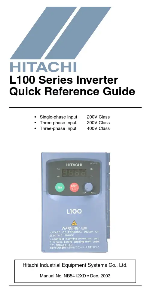
•Single-phase Input 200V Class •Three-phase Input 200V Class •Three-phase Input400V ClassManual No. NB5412XD • Dec. 2003Hitachi Industrial Equipment Systems Co., Ltd.HITACHIL100 Series Inverter Quick Reference GuideCaution: Be sure to read the L100 Inverter Manual andfollow its Cautions and Warnings for the initial productinstallation. This Quick Reference Guide is intended forreference use by experienced users in servicing existinginstallations.Power Circuit Terminals–002NFE/NFU, –004NFE/NFU, –005NFEJumper+1L1L2N/L3U/T1V/T2W/T3ChassisGround–007 to 022NFE/NFU, –037LFU, 004 to 040HFE/HFUJumper+1L1L2N/L3U/T1V/T2W/T3ChassisGround–055LFU, –075LFU, 055HFE/HFU, 075HFE/HFU Jumper+1L1L2N/L3U/T1V/T2W/T3ChassisGroundControl Circuit TerminalsTerminalName Description Ratings and NotesP24+24V for logic inputs24VDC supply, 30 mA max.(Notes: Do not use for network powerDo not short to terminal L)1, 2, 3, 4, 5Intelligent (program-mable) discrete logicinputs 27VDC max. (use P24 or an external supply referenced to terminal L), 4.7k Ω input impedance11, 12Discrete logic outputs 50 mA max. ON current,27 VDC max. OFF voltage L (top row)GND for logic inputs Sum of input 1 to 5 currents (Note: Do not ground)CM2Common for logic outputs 100 mA max for sum of terminals 11 and 12 currents FMPWM output0 to 10VDC, 1 mA max., 50% duty cycle L (bottom row)Common for analog inputs Sum of OI, O, and H currents (return)OIAnalog input, current4 to 19.6 mA range, 20 mA nominalH O OI FM P24L Analog inputsAnalog outputsAlarm relayLogic outputsLogic inputsL 54321CM21211AL0AL1AL2OAnalog input, voltage0 to 9.6 VDC range, 10VDC nominal, 12VDC max., input impedance 10 k ΩH +10V analog reference 10VDC nominal, 10 mAmax.AL0Relay common contact Contact rating Max resistive load = 250V AC, 2.5A; 30VDC 3A;Max inductive load = 250V AC, 0.2A; 30VDC 0.7AMinimum load = 5VDC 100mA,100V AC, 10mAAL1Relay contact, normally closed during RUN AL2Relay contact,normally open during RUNTerminal NameDescription Ratings and NotesBasic Wiring DiagramThe following wiring diagram shows the power and motor connec-tions for basic operation. The optional signal input wiring supports external Fwd and Rev Run command, and a speed potentiometer.(L1)R (L2)S (N/L3)T(T2)V(T3)W(T1)U MotorForwardLOHReverseAlarm contacts, 1 Form CRun signalFrequency arrival signal Open collector outputs:External speed reference pot.L100From 3-phase power input source (See specifications label on inverter for details)Logic output commonLoadLoadAnalog common Analog referenceP2421CM21211AL0AL1AL2Inputs:Inverter Keypad Operation•Run/Stop LED – ON when the inverter output is ON and the motor is developing torque, and OFF when the inverter output is OFF (Stop Mode).•Program/Monitor LED – ON when the inverter is ready for parameter editing (Program Mode). It is OFF when the parameter display is monitoring data (Monitor Mode).•Run Key Enable LED – ON when the inverter is ready to respond to the Run key, OFF when the Run key is disabled.•Run Key – Press this key to run the motor (the Run Enable LED must be ON first). Parameter F_04, Keypad Run Key Routing, determines whether the Run key generates a Run FWD or Run REV command.•Stop/Reset Key – Press this key to stop the motor when it is running (uses the programmed deceleration rate). This key will also reset an alarm which has tripped.(continued, next page...)Hz POWER ARUN PRGMINMAXHITACHIFUNC.STR1250.0Parameter Display Run/Stop LEDProgram/Monitor LEDRun Key Enable LEDRun Key Power LEDDisplay Units LEDs Hertz AmperesPotentiometer Enable LED Potentiometer Stop/Reset KeyFunction KeyUp/Down Keys Store Key•Potentiometer – Allows an operator to directly set the motor speed when the potentiometer is enabled for output frequency control.•Potentiometer Enable LED – ON when the potentiometer is enabled for value entry.•Parameter Display – A 4-digit, 7-segment display for parame-ters and function codes.•Display Units: Hertz/Amperes – One of these LEDs will be ON to indicate the units associated with the parameter display.•Power LED – ON when the power input to the inverter is ON.•Function Key – This key is used to navigate through the lists of parameters and functions for setting and monitoring parameter values.•Up/Down Keys – Use these keys alternately to move up or down the lists of parameter and functions shown in the display, and to increment/decrement values.•Store Key – When the unit is in Program Mode and the operator has edited a parameter value, press the Store key to write the new value to the EEPROM.Keypad Navigation Mapc 91c 0112b 89b 0112A 98A 0112121212C ––12b ––12A ––F 04F 0112d 09d 0112o.0123.4Edit12Increment/decrement valueWrite datato EEPROMDisplay dataMonitor Mode Program ModeFUNC.STRFUNC.FUNC.12Return to parameter listFUNC.FUNC.Store as powerup defaultpowerdownSelect ParameterEdit ParameterPowerup TestThe Powerup Test procedure uses minimal parameter settings to run the motor. The procedure describes two alternative methods for commanding the inverter: via the inverter keypad, or via the logic terminals.•Check power input and motor output wiring (see page4 diagram).•If using logic terminals for testing, verify correct wiring on [P24], [FW], [H], [O], and [L] (bottom row) per the diagram on page4.•Reverse [RV] input wiring (defaults to terminal [2]) is optional.Step Description Via Keypad Via LogicTerminals1Set speed command source setting A_01 = 00(keypad pot.)A_01 = 01,[H–O–L] input2Set Run FW command source A_02 = 02(Run key)A_02 = 01,[FW] input3Set Run REV command source —C_02 = 01,[RV] input4Set motor base freq.A_03 = 605Set keypad display to monitor freq.Access D_01, press Func key, display will show 0.0Perform safety check Disconnect load from motor6Turn keypad pot.to MIN position Ensure voltage on [O]—[L] termi-nals= 0V7Run Forward command Press Run key Turn ON the[FW] terminal8Increase speed Rotate keypadpot. CW dir.Increase voltage at [O]9Decrease speed Rotate keypadpot. CCW dir.Decrease voltage at [O]10Stop motor Press Stop key Turn OFF the[FW] terminal11Run Reverse command (optional)—Turn ON the [RV]terminal12Stop motor—Turn OFF the[RV] terminalError CodesThe L100 series inverters will trip on over-current, over-voltage, and under-voltage to protect the inverter. The motor output turns OFF, allowing the motor to free-run to a stop. Press the Stop/Reset key to reset the inverter and clear the error.Basic Error CodesErrorCode Name Probable Cause(s)E01Over current event whileat constant speed •Inverter output was short-circuited •Motor shaft is locked•Load is too heavy•A dual-voltage motor is wired incorrectlyNote: The L100 will over current trip at nominally 200% of rated currentE02Over current event duringdecelerationE03Over current event duringaccelerationE04Over current event forother conditions •DC braking power(A_54) set too high•Current transformer / noise errorE05Overload protection•Motor overload is detected by theelectronic thermal functionE07Over voltage protection•DC bus voltage exceeds a threshold,due to regenerative energy from motor E08EEPROM error•Built-in EEPROM memory experi-enced noise, high temperature, etc. E09Under-voltage error•DC bus voltage decreased enough tocause a control circuit faultE11E22CPU error•Built-in CPU had internal errorE12External trip•[EXT] input signal detectedE13USP (Unattended StartProtection)•When (USP) was enabled, an error occurred when power was applied while a Run signal was presentE14Ground fault•A ground fault was detectedbetween the inverter output and themotor. This feature protects theinverter, and does not protect humans. E15Input over-voltage•Input voltage was higher than thespecified value, 60 sec. after powerup E21Inverter thermal trip•Inverter internal temperature isabove the thresholdError Trip ConditionsUse function code D_08 to access the error trip conditions for the current error as shown in the table below. Use the Up and Down arrow keys to scroll through the trip condition parameters.E35Thermistor•Thermistor input, [THM] and [L], is over the temp. threshold---Under-voltage (brown-out) with output shutoff•Low input voltage caused theinverter to turn OFF the motor output and try to restart. If unsuccessful, a trip occurs.StepDisplay1. Access D_08d 082. Press Function KeyIf no error:_ _ _If error exists:Exx(error code)3. Press Up/Dn key (if error exists)Output frequency at trip point:10.0Motor current at trip point:0.025DC bus voltage at trip point:189.8Error CodeNameProbable Cause(s)12Restoring Factory Default SettingsActionDisplayFunction/ParameterPress ,or as needed.b --“B” Group selectedPress .b 01First “B” Group parame-terPress/holduntil...b 85Country code forinitialization selected Press . If setting iscorrect, then skip next step.0200 = Japan 01 = Europe02 = United StatesTo change country code, press or to set; to store.Press .b 85Country code forinitialization selected Press .b 84Initialization function selectedPress .000 = disable initialization, clear trip history only Press .011 = enable initialization Press .b 84Initialization now enabled to restore all defaultsPress/hold , ,and . Do not release yet.b 84First part of key sequencePress/hold (STOP)for 3 seconds, then release.d 00Final part of special sequence, “D_00” is flashingNow release the all keys together, only after “D_00” display begins blinking.EU USA JP Default parameter country code shown during initializationInitialization is complete.d 01Function code for output frequency monitor shownFUNC.12FUNC.1FUNC.12STR FUNC.2FUNC.1STR FUNC.12Note: After initializing the inverter, use the Powerup Test on page 8 to get the motor running again.Parameter Tables“D” Group: Monitoring FunctionsFunc. Code Name / DescriptionUnits D_01Output frequency monitor Hz D_02Output current monitor A D_03Rotation direction monitor—D_04Process variable (PV), PID feedback monitor %D_05Intelligent input terminal status—D_06Intelligent output terminal status—D_07Scaled output frequency monitor(output frequency x B_86 scale factor)User-defined D_08Trip event monitor —D_09Trip history monitor—DirectionForward Stop Reverse21435Terminal NumbersON OFF1211AL Terminal NumbersON OFFTrip History Navigation MapE 0760.0124.00270.01212d 0812o.00Display dataMonitor Mode12FUNC.FUNC.d 09____NoError code Output frequency at trip point Motor current at trip point DC bus voltage at trip pointFUNC.Y esNo errorError (n-1) exists?NoY esE 03E 05____No historyFUNC.Error (n-2) exists?NoY esFUNC.____FUNC.FUNC.12FUNC.No historyError exists?Parameter tables for user-settable functions follow these conven-tions:•Some parameters specify an option code. Where applicable, the options codes will be in a bulleted list in the Name/Description column.•The default values apply to all models unless otherwise noted for each parameter... –FE (Europe) / – FU (U.S.) / –FR (Japan).•Some parameters cannot be edited during Run Mode, and certain Software Lock settings (B_31) can prohibit all edits. If in doubt, place the inverter in Stop Mode or consult the inverter manual for details.“F” Group: Main Profile ParametersFunc.Code Name / Description DefaultValueSetValueF_01Output frequency setting0.0 F_02Acceleration (1) time setting10.0 F_03Deceleration (1) time setting10.0 F_04Keypad Run key routing•00Forward•01Reverse00“A” Group: Standard FunctionsFunc.Code Name / DescriptionDefaultValue–FE / –FU /–FRSetValueA_01Frequency source setting•00Keypad potentiometer•01Control terminal•02Function F_01 setting01 / 01 / 00A_02Run command source setting•01Input terminal FW or RV (assign-able)•02Run key on keypad, or digitaloperator01 / 01 / 02A_03Base frequency setting50.0 / 60.0 /60.0A_04Maximum frequency setting50.0 / 60.0 /60.0A_11O/OI–L input active range startfrequency0.0A_12O/OI–L input active range end frequency0.0A_13O/OI–L input active range start voltage0A_14O/OI–L input active range end voltage100A_15O/OI–L input start frequency enable•00Use A_11 starting value)•01Use 0 Hz01A_16External frequency filter time constant8A_20Multi-speed frequency setting0A_21 A_22 A_23 A_24 A_25 A_26 A_27 A_28 A_29.. ..A_35Multi-speed frequency settings0 / 0 / 50 / 0 / 100 / 0 / 150 / 0 / 200 / 0 / 300 / 0 / 400 / 0 / 500 / 0 / 600 / 0 / 0A_38Jog frequency setting 1.0 A_39Jog stop mode•00Free-run stop, jogging disabledduring motor run•01Controlled deceleration, joggingdisabled during motor run•02DC braking to stop, joggingdisabled during motor run00A_41Torque boost method selection•00Manual torque boost•01Automatic torque boost00A_42Manual torque boost value11 A_43Manual torque boost frequency adjust-ment10.0A_44V/f characteristic curve selection•00V/f constant torque•01V/f variable torque00A_45V/f gain setting100 A_51DC braking enable•00Disable•01Enable00 A_52DC braking frequency setting0.5 A_53DC braking wait time0.0 A_54DC braking force during deceleration0 A_55DC braking time for deceleration0.0 A_61Frequency upper limit setting0.0 A_62Frequency lower limit setting0.0 A_63A_65A_67Jump (center) frequency setting0.0A_64 A_66 A_68Jump (hysteresis) frequency widthsetting0.5A_71PID Enable•00PID operation OFF•01PID operation ON00A_72PID proportional gain 1.0A_73PID integral time constant 1.0A_74PID derivative time constant0.0A_75PV scale conversion 1.00A_76PV source setting•00[OI] terminal (current input)•01[O] terminal (voltage input)00A_81A VR function select•00A VR enabled•01A VR disabled•02A VR enabled except during decel02 / 00 / 02“B” Group: Fine-tuning FunctionsA_82A VR voltage select 230/230/200400/460/400A_92Acceleration (2) time setting 15.0A_93Deceleration (2) time setting15.0A_94Select method to switch to Acc2/Dec2 profile•002CH input from terminal •01transition frequency00A_95Acc1 to Acc2 frequency transition point 0.0A_96Dec1 to Dec2 frequency transition point 0.0A_97Acceleration curve selection •00Linear •01S-curve 00A_98Deceleration curve selection •00Linear •01S-curve00Func. Code Name / DescriptionDefault Value –FE / –FU /–FRSet ValueB_01Selection of automatic restart mode •00Alarm output after trip, automatic restart disabled •01Restart at 0Hz•02Resume operation after frequency matching•03Resume previous freq. after freq. matching, then decelerate to stop and display trip info00B_02Allowable under-voltage power failure time1.0B_03Retry wait time before motor restart1.0B_12Level of electronic thermal setting Ratedcurrent ofeach inverter B_13Electronic thermal characteristic•00Reduced torque•01Const. torque01 / 01 / 00B_21Overload restriction operation mode•00Disabled•01Enabled for accel and constantspeed•02Enabled for constant speed only01B_22Overload restriction setting Ratedcurrentx 1.25B_23Deceleration rate at overload restriction 1.0B_31Software lock mode selection•00Low-level access, [SFT] blocksedits•01Low-level access, [SFT] blocksedits (except F_01 and Multi-speedparameters)•02No access to edits•03No access to edits except F_01 andMulti-speed parameters01B_32Reactive current settingNote: For Japanese (–FR) versions, only–055LFR, –055HFR, –075LFR, and–075HFR models support this function.58% rated currentB_81[FM] terminal analog meter adjustment80B_82Start frequency adjustment0.5B_83Carrier frequency setting 5.0 / 5.0 /12.0B_84Initialization mode (parameters or triphistory)•00Trip history clear•01Parameter initialization00B_85Country code for initialization•00Japan version•01Europeversion•02US version01 / 02 / 00B_86Frequency scaling conversion factor 1.0B_87STOP key enable•00Enable•01Disable00“C” Group: Intelligent Terminal FunctionsB_88Restart mode after FRS •00Restart from 0Hz•01Restart from frequency detected from actual speed of motor00B_89Data select for digital operator OPE-J •01Output frequency (D_01)•02Output current (D_02)•03Motor direction (D_03)•04PID PV feedback (D_04)•05Input states for input terminals (D_05)•06Output states for output terminals (D_06)•07Scaled output frequency (D_07)01Func. Code Name / DescriptionDefault Value –FE / –FU /–FRSet ValueC_01Terminal [1] function Fifteen option codes available (see page 21)00C_02Terminal [2] function 01C_03Terminal [3] function 02 / 16 / 02C_04Terminal [4] function 03 / 13 / 03C_05Terminal [5] function 18C_11Terminal [1] active state•00Normally open [NO]•01Normally closed [NC]00C_12Terminal [2] active state00C_13Terminal [3] active state00C_14Terminal [4] active state00 / 01 / 00C_15Terminal [5] active state00C_21Terminal [11] function Six optioncodes available(see page22)01C_22Terminal [12] function00 C_23[FM] signal selection Three optioncodes available(see page22)00C_31Terminal [11] activestate (–FU)•00Normallyopen (NO)•01Normallyclosed (NC)— / 00 / —Reserved (–FE / –FR)00 / — / 00 C_32Terminal [12] activestate (–FU)— / 00 / —Terminal [11] activestate (–FE / –FR)00 / — / 00C_33Alarm relay terminalactive state01C_41Overload level setting Ratedcurrent ofeach inverter C_42Frequency arrival setting for accel0.0C_43Arrival frequency setting for decel0.0C_44PID deviation level setting 3.0C_91Debug mode enable•00Display•01No display 00Func.Code Name / DescriptionDefaultValue–FE / –FU /–FRSetValueIntelligent Input Terminal ListingSymbol Code Input Terminal NameFWD00Forward Run/StopRV01Reverse Run/StopCF102Multi-speed select, Bit 0 (LSB)CF203Multi-speed select, Bit 1CF304Multi-speed select, Bit 2CF405Multi-speed select, Bit 3 (LSB)JG06Jogging2CH092-stage accel and decelFRS11Free-run stopEXT12External tripUSP13Unattended start protectionSFT15Software lockAT16Analog input voltage/current sel.RS18Reset inverterPTC19PTC thermistor thermal protectionIntelligent Output Terminal ListingAnalog Input ConfigurationThe following tables show the parameter settings required for vari-ous analog input signal types.Analog Output Function ListingThe following table shows all three functions available for assign-ment to the analog output terminal:•Terminal [FM], option set by C_23Symbol Code Input Terminal NameRUN 00Run signalFA101Freq. arrival type 1 – constant speed FA202Freq. arrival type 2 – over-frequency OL 03Overload advance notice signal OD 04Output deviation for PID control AL05Alarm signal[AT]External Frequency Command InputOFF [O] — [L]ON[OI] — [L](not assigned to any inputterminal)Summation of [O] — [L] and [OI] — [L]Option Code Function Name Description Corresponding Signal Range 00Output frequency Actual motor speed, represented by PWM signal0 to max. freq. in Hz01Output currentMotor current (% of maximum rated output current), represented by PWM signal0 to 200%02Digital output frequencyOutput frequency 0 to max. freq. in HzNotes:。
DHC东方日立DHVECTOL-DI/HI/HT/HS系列变频调速系统技术手册东方日立(成都)电控设备有限公司目录第一章:变频技术的发展起因以及东方日立变频设备 (3)1. 变频技术的发展起因 (3)2. 变频技术的作用 (3)3. 变频技术的发展过程如下 (3)4. 变频调速装置的功能 (6)5. 东方日立公司变频调速装置 (9)6. 高压变频器适应的技术标准 (13)7. 东方日立变频器型号定义 (14)8. 东方日立变频器基本技术参数和配置 (16)8.1 全国产化方式生产的高压变频器 (16)8.2 东方日立CKD引进型大功率系列变频器 (23)9. 制作工艺以及检验试验 (29)第二章:变频器原理 (32)1. 基本电子电路原理 (32)2.IGBT的基本特性 (33)3.IGBT的主要参数和特点 (34)4. 东方日立公司DHVECTOL型变频技术 (38)5. 变频调速节能原理 (52)6. 完整的调速系统构成 (57)第三章:运输、储存、使用及安装 (59)1. 运输 (59)2. 储存 (59)3. 变频器工作要求、安装及注意事项 (59)4. 变频器的接口以及作用 (66)5. 变频器功能设定 (68)6. 变频器自诊断 (75)第四章:变频器面板以及操作 (81)1. 控制面板外观 (81)2. 按键说明: (81)3. 系统工作状态说明 (82)4. 控制方式说明 (82)附录1:常见问题的处理 (105)附录2:东方日立公司变频器生产检验流程图 (108)第一章:变频技术的发展起因以及东方日立变频设备1.变频技术的发展起因工业革命以来,人们都在孜孜不倦地研究电的使用和任意变换,研究如何更好地完成交流电机的调速、传动以及过程的自动控制,随着工业革命步伐的持续加快,人们更想利用电子技术将固定频率的交流电变换为任意频率的交流电,从而可以满足机器设备的不同需要。
很长时间以来,由于电力电子器件的发展跟不上人们的需要,使得固定频率的交流电的使用受到一定限制。
东方日立(成都)电控设备有限公司高压大功率变频器HI系列用户使用说明书( Ver.A )目录1.简述 (3)2.变频装置和外部的接口信号列表 (4)3.变频操作 (7)3.1 互锁 (7)3.2 电机速度控制 (7)3.3 启/停变频器的操作流程 (8)4.显示界面 (11)4.1 条形图 (11)4.2 故障显示 (13)4.3 互锁纪录显示 (17)4.4 DIO(输入和输出接触点显示)界面 (18)附:常见故障及处理 (19)1、简述日本日立公司生产的High V oltage Inverter产品是一种交流电机的速度调节控制装置。
变频器的控制方式采用多级PWM叠加技术,结构采用多个变频器单元串联叠加输出的方式。
日立公司的6KV(10KV)系列变频器每相5(8)级单元,变频器输出电压由所有单元输出叠加而成,波形非常接近于正弦波,谐波含量很低,极大的减小了对交流电机的谐波污染。
整套变频装置由旁通柜,变压器柜,功率单元柜和控制柜四部分组成。
在旁通柜内,装有高压断路器和隔离刀闸等,可实现变频和工频的切换,当变频器在运行中发生重故障时,变频器发出变频切换到工频的指令,也可根据需要,人为的切换到工频。
在变压器柜内,装有多重移相变压器,原边绕组采用星形接法,副边绕组采用延边三角形接法和星形接法,可有效的抵消电网中的偶次谐波,并可有效的滤除某些奇次谐波,尽量减少变频器电源的谐波污染,变压器能承受系统过电压和变频装置产生的共模电压以及谐波的影响。
在功率单元柜内装有功率单元,变频器的输出电压为每个单元输出的PWM波形叠加后的输出。
在控制柜内,装有控制各个回路启停的开关和控制各个功率单元协调工作的控制板,以及整套变频装置同外部系统的接口等。
对变频器的启停操作,通过切换开关,既可以通过就地的按钮控制,又可通过远方的DCS控制来完成。
变频装置根据DCS给出的速度调节信号自动的控制电机的转速,并且在就地和远方都可以监视变频装置的状态。
日立变频器SJ300系列说明书接线图:1、动力电源输入:RST(三相接入,短接板PD+---P),动力电源输出:UVW(三相接电机);2、报警AL0(公共端),AL1(NC),AL2(NO);3、2进制控制:正转:P24----NO----FW(正转),P24----NO----‘5’(C005设定端子功能01,),P24----NO----‘4’(C004设定端子功能02,)P24----NO----‘3’(C003设定端子功能03,)出厂时为源型输入(要改为漏型时,取下PLC—CM1间跳线,在P24及PLC跳线)。
4、参数设定:运行时要改变模式,应选择b031(软件锁选择),改变值时,按“STR”键。
A、加速时间设定F002(出厂30s);B、加速时间设定F003(出厂30s);C、电机转向设定F004(出厂00—正向,01---反向);D、A021~A035(多端速度设定1~15,A021设定多端速1—快速,A022设定多端速2—慢速);E、A003电机额定频率,A004电机最大频率,A061频率设定上限,A062频率设定下限,A082电机电压选择(4-20)F、b012电子热保护门限设定(4-39)G、b021过载限制设定(00—无效,01---恒速及加速时有效),b022过载限制门限设定(电流值)H、变频器输入2进制控制可以使用输出模块直接控制(使用外部电源,可以省略中继),G、d005可以监视FW,及8个智能端子的on/off状态。
I、A001及A002设定01,表示频率和运行控制使用端子方式。
A003基频设定。
注意恢复出厂值的设置:第一步:b084设置为01(参数初始化);第一步:按住FUNC,UP,DOWN三个键,再按一下stop/reset键,当显示闪烁时,松开所有按键即可。
故障信息说明原因措施备注恒速运转1、负荷突然变小E01 过流2、输出短路1、增加变频器容量CT检测3、L-PCB与IPM-PCB连接缆线出错2、使用矢量控制方式4、接地故障减速运转1、速度突然变化E02 过流2、输出短路1、检查输出各项CT检测3、接地故障2、延长减速时间4、减速时间太短3、使用模糊逻辑加减速5、负载惯量过大4、检查制动方式6、制动方法不合适加速运转1、负荷突然变化1、使用矢量控制A0选4过流2、输出短路2、转矩提升3、接地故障3、延长加速时间E03 4、启动频率调整太高4、增大变频器的容量CT检测5、转矩提升太高5、使用模糊逻辑加减速控制功能6、电机被卡住6、缩短变频器与电机之间距离7、加速时间过短8、变频器与电机之间连接电缆过长E04 停止时1、CT损坏CT检测过流2、功率模块损坏过载1、负荷太重1、减轻负荷E05 2、电子热继电器门限设置过小2、增大变频器的容量3、增大电子热继电器门限值制动电阻1、再生制动时间过长1、减速时间延长E06 过载保护2、L-PCB与IPM-PCB连接缆线出错2、增大变频器的容量3、A38设定为004、提高制动使用率1、速度突然减小1、延长减速时间2、负荷突然脱落2、增大变频器的容量E07 过压3、接地故障3、外加制动单元4、减速时间太短5、负荷惯性过大6、制动方法有问题1、周围噪声过大1、移去噪声源2、机体周围环境温度过高2、机体周围应便于散热、空气E08 EEPROM 3、L-PCB损坏流动良好故障4、L-PCB与IPM—PCB连接线松动3、更换制冷风扇或损坏4、更换相应元气件5、变频器制冷风扇损坏5、重新设顶一遍参数1、电源电压过低1、改变供电电源质量2、接触器或空开触点不良2、更换接触器或空开E09 欠压3、10分钟内瞬间掉电次数过多3、将F11设为380V4、启动频率调整太高4、将主线各节点接牢5、F11选择过高5、增加变压器容量6、电源主线端子松动7、同一电源系统有大的负载启动8、电源变压器容量不够1、CT损坏更换E10 CT出错2、CT与IPM—PCB上J51连线松了3、逻辑控制板上OP1损坏大部分问题是OP1损坏4、可能84与RS、DM、ZNR损坏1、周围噪声过大1、重新设置参数E11 CPU出错2、误操作2、移去噪声源3、CPU损坏3、更换CPUE12 外部跳闸1、外部控制线路有故障1、检测外部控制线路1、当选择此功能时,一旦INV处于1、变频器停止运行操作时E13 USP出错运行状态时,突然来电会发生此应该将运行开关关闭后再故障信息拉掉电源、不能直接拉电1、周围环境过于潮湿,电缆绝缘1、断开INV的输出端子,用摇性下降或电机绝缘性下降表检查电机的绝缘性,2、变频器输出接地不好2、换线缆,或烘干电机3、电机接地不好3、更换其它零部件E14 INV输出4、加、减速时间过短4、有时IPM-PCB是好的,但接地故障5、CT故障、L-PCB故障DM损坏6、IPM损坏7、L-PCB与IPM—PCB连接线松动、或损坏8、如果使用电控柜,可能输出输入电缆磨损与电控柜连接一体带电9、变频器输出电缆断线10、输出端子松动11、电机线圈断线12、电机功率太小13、由于噪声引起的误动作1、电源电压过高1、能否降低电源电压E15 电源电压2、F11设置过低2、根据实际情况选择F11值过高3、AVR功能没有起作用3、输入侧安装AC电抗器E16 瞬间电源1、电源电压过低故障2、接触器或空开触点不良E17~E20 选件板故障E21 变频器内部1、制冷风扇不转/变频器内部温度过高SJ300 温度过高2、散热片堵塞SJ200 E23 CPU与闸阵列连接复杂SJ300故障1、三相电源缺相1、检查供电电源E24 缺相保护2、接触器或空开触点不良2、更换接触器或空开3、L-PCB与IPM-PCB连线不良3、换一块L-PCB仍旧不好、再4、IPM与DM连线换连线仍旧不好,则IPM—(仅限30KW以上)PCB损坏E30 IGBT故障1、暂态过流(SJ300无E31、E32、E33等)1、负荷突然改变2、变频机体温升过高3、周围环境过于潮湿,电缆绝缘E31、E32、E33、E34主要是E31 恒速过流性下降或电机绝缘性下降输出侧的原因4、变频器输出接地不好解决办法使用模糊控制5、电机接地不好即A59:26、IPM损坏1、减速时间设置不当2、速度突然变化E32 减速过流3、输出短路4、接地故障5、IPM损坏1、速度突然增加2、负荷突然变化3、输出短路E33 加速过流4、接地故障5、启动频率调整太高6、转矩提升太高7、电机被卡住8、IPM损坏9、载波频率过高10、IPM-PCB损坏(仅限J300-750HFE4以上型号)11、PM与底座的散热硅胶涂抹的不均匀1、变频器震动过大2、IPM损坏E34 停止时3、变频器没有垂直安装过流4、环境温度过高5、内部电源损坏6、制冷风扇不转E35 电机过热热敏电阻与变频器智能端子连接后如果电机温度过高,变频器跳闸E60 通信故障通信网络看门狗超时1、复位信号被保持1、按下(1键或2键)键即能恢复ˉˉˉˉ上面四横杠2、面板和变频器之间出现错误2、再一次接通电源————中间四横杠1、关断电源时显示__U 1、输入电压不足时____下面四横杠无任何跳闸历史时显示————闪烁1、逻辑控制板损坏2、开关电源损。
IOD-40249/2016OPERATION MANUALMODELSAir Handling UnitFXTQ09TAVJUA FXTQ09TAVJUD FXTQ12TAVJUA FXTQ12TAVJUD FXTQ18TAVJUA FXTQ18TAVJUD FXTQ24TAVJUA FXTQ24TAVJUD FXTQ30TAVJUA FXTQ30TAVJUD FXTQ36TAVJUA FXTQ36TAVJUD FXTQ42TAVJUA FXTQ42TAVJUD FXTQ48TAVJUA FXTQ48TAVJUD FXTQ54TAVJUA FXTQ54TAVJUD FXTQ60TAVJUAFXTQ60TAVJUDSYSTEM Inverter Air ConditionersRead these instructions carefully before installation. Keep this manual in a handy place for future reference. This manual should be left with the equipment owner.Lire soigneusement ces instructions avant l’installation.Conserver ce manuel à portée de main pour référence ultérieure. Ce manuel doit être donnéau propriétaire de l’équipement.Lea cuidadosamente estas instrucciones antes de instalar.Guarde este manual en un lugar a mano para leer en caso de tener alguna duda. Este manual debe permanecer con el propietario del equipo.•Do not allow children to play on or around the unit to prevent injury.•The heat exchanger fins are sharp enough to cut. To avoid injury, wear gloves or cover the fins while work-ing around them.•Do not put a finger or other objects into the air inlet or air outlet. The fan is rotating at high speed and will cause injury.•Check the unit foundation for damage on a continu-ous basis, especially if it has been in use for a long time. If left in a damaged condition the unit may cause injury.•Placing a flower vase or other containers with water or other liquids on the unit could cause a shock or fire if a spill occurs.•Never touch the internal parts of the controller. Do not remove the front panel because some parts in-side are dangerous to touch. To check and adjustinternal parts, contact your dealer.•Do not use the heat pump for any other purposes other than comfort cooling or heating. Do not use the unit for cooling precision instruments, food, plants, animals or works of art.•Do not place items under the indoor unit as they may be damaged by condensates that may form if the humidity is above 80% or if the drain outlet gets blocked.•Before cleaning, stop the operation of the unit by turning the power off or by pulling the supply cord out from its receptacle. Otherwise, an electric shock and injury may result.•Do not wash the heat pump with excessive water. An electric shock or fire may result.•Avoid placing the controller in a spot splashed with water. Water entering the controller may cause an electric shock or damage the internal electronic parts.•Do not operate the heat pump when using a room fumigation type of insecticide. Failure to observe this could cause the chemicals to be deposited in the unit and can endanger the health of those who are hyper-sensitive to chemicals.•The appliance is not intended for use by young chil-dren or infirm persons without supervision.•The remote controller should be kept away from chil-dren so they cannot play with it.•Consult with the installation contractor for cleaning.•Incorrect cleaning of the inside of the heat pump could make the plastic parts break and cause water leakage or electric shock.•Do not touch the air inlet or aluminum fin of the heat pump as they can cut and cause injury.•Do not place objects in direct proximity of the out-side unit. Do not let leaves and other debris accumu-late around the unit. Leaves are a hotbed for small animals which can enter the unit. Once inside the unit, animals can cause the unit to malfunction and cause smoke or fire when they make contact withelectrical parts.•Never press the button of the remote controller with a hard, pointed object. The remote controller may be damaged.•Never pull or twist the electric wire of the remote con-troller. It may cause the unit to malfunction.•Do not place appliances that produce open flames in places that are exposed to the air flow of the unit or under the indoor unit. It may cause incomplete com-bustion or deformation of the unit due to the heat.•Do not expose the controller to direct sunlight. The LCD display can become discolored and may fail to display the data.•Do not wipe the controller operation panel with ben-zene, thinner, chemical dust cloth, etc. The panel may get discolored or the coating can peel off. If it is heavily dirty, soak a cloth in water-diluted neutral detergent, squeeze it well and wipe the panel clean.Then wipe it with another dry cloth.•Dismantling of the unit, disposal of the refrigerant, oil, and additional parts, should be done in accor-dance with the relevant local, state, and national regu-lations.•Operate the heat pump in a sufficiently ventilated area and not surrounded by obstacles. Do not use the heat pump in the following places.a.Places with a mist of mineral oil, such as cuttingoil.b.Locations such as coastal areas where there is alot of salt in the air.c.Locations such as hot springs where there is a lotof sulfur in the air.d.Locations such as factories where the power volt-age varies a lot.e.In cars, boats, and other vehicles.f.Locations such as kitchens where oil may splat-ter or where there is steam in the air.g.Locations where equipment produces electromag-netic waves.h.Places with an acid or alkaline mist.i.Places where fallen leaves can accumulate orwhere weeds can grow.•Do not attempt to do electrical work or grounding work, unless you are licensed to do so. Consult with your dealer for electrical work and grounding work.•Pay attention to operating sound. Be sure to use the following places:a.Places that can sufficiently withstand the weightof the heat pump yet can suppress the operat-ing sound and vibration of the heat pump.b.Places where warm air from the air outlet of theoutside unit or the operating sound of the out-side unit does not annoy neighbors.•Consult your dealer if the heat pump in operation gen-erates unusual noise.•Make sure that the drainpipe is installed properly to drain water. If no water is discharged from the drain-pipe while the heat pump is in the cooling mode, the drainpipe may be clogged with dust or dirt and water leakage from the indoor unit may occur. Stop oper-ating the heat pump and contact your dealer.2.3.MAINTENANCE•Only a qualified person is allowed to perform mainte-nance without daily maintenance.•Before touching any of the connection wirings, be sure to turn off all power supply switches.•For installation of optional parts, only a qualifited person is allowed to do so.Be sure to use optional parts specified by the manufac-turer. Installation in your own manner may result in wa-ter leakage, electric shock or fire.•Do not use flammable material (e.g. hair-spray or insec-ticide) near the product.•Only proceed with the unit cleaning after stopping the operation and turning the power supply off.Failure to do so may result in electric shocks or injury.•Do not wash the heat pump or air handler with water.Failure to do so may result in an electric shock.•Consult with installation contractor for cleaning the inside of the air handler.Wrong cleaning procedures may break plastic parts or cause water leakage or electric shock.•Use a stable prep stand.Pay extra attention when cleaning the air handler. (Maintenance and inspection)•Clean the drain pan periodically. The drain pipes clogged with dust will cause water leakage.•For cleaning, consult with your Daikin dealer. (Before each season when cooling or heating is required, clean the air handler.)•If the area around the indoor unit is very dusty, use a dust proof cover (local procurement).(Cleaning the inside of the indoor unit)•It is necessary to clean the inside of the indoor unit peri-odically.Since the cleaning requires special technologies, requesta Daikin dealer to clean them.(Electric heater replacement interval)•The electric heater should be replaced every ten years.This replacement interval is a guideline for ensuring safe and trouble-free operation of the product for many years. (Cleaning the air filter)•The air filter is an optional accessory.EXPLANATION:•Removing the air filter except when cleaning the air han-dler may result in accidents.•Replace the filter when one of the following messages displayed on the bottom of remote controller screen.- Time to clean filter & element- Time to clean filter•If using the air handler under very dusty environment, increase the frequency of air filter cleaning.•Reset the filter sign on main menu of remote controller.Refer an operation manual of remote controller for de-tail.•Consult dealer to change filter setting time to display fil-ter change alarm on remote controller screen. (The de-fault factory setting is 2500 hours.)•There are the following time, display pattern: 1250, 2500, 5000, 10000.•Do not allow the indoor unit to get wet as it may cause an electric shock or fire._______________________________________________ 4. PRECAUTIONSIf the following phenomenon occurs, contact your dealer.•Any abnormalities in the operation of the heat pump or air handler such as smoke or fire could result in severe injury or death.Turn off the power and contact your dealer immediately for instructions._______________________________________________ Phenomenon•The unit may operate with the airflow rate at high speed even though the airflow rate was set to low speed using the remote controller during ELECTRIC HEATER opera-tion.Take the following actions before contact.Check to see if an optional electric heater is installed.The unit operates with the airflow rate at high speed dur-ing ELECTRIC HEATER operation regardless of the re-mote controller airflow rate setting or display.Phenomenon•The safety devices such as fuse, breaker, ground fault interrupter, etc. often operate or operations of the opera-tion switch are unstable.Take the following actions before contact.Turn off the switch.•If the ON/OFF switch does not properly work, Take the following actions before contact.Turn off the main power switch.Phenomenon•Water leaks out from the air handle r.Take the following actions before contact.Stop the operation.Phenomenon•Error message is displayed. See the remote controller operation manual for details.Inform the dealer of the details being displayed on the remote controller.。