AS250电脑控系统参数设置及操作培训.pptx
- 格式:pptx
- 大小:871.35 KB
- 文档页数:21
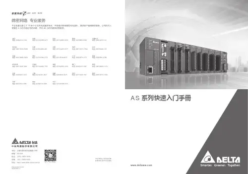
AS系列快速入门手冊绵密网络 专业服务中达电通已建立了70余个分支机构及服务网点,并塑建训练有素的专业团队,提供客户最满意的服务,公司技术人员能在2小时内回应您的问题,并在48小时内提供所需服务。
中达电通公司版权所有如有改动,恕不另行通知400 - 820 - 9595扫一扫,关注官方微信沈阳电话:(024)2334-1160哈尔滨电话:(0451)5366-5568长春电话:(0431)8892-5060呼和浩特电话:(0471)6297-808北京电话:(010)8225-3225天津电话:(022)2301-5082济南电话:(0531)8690-6277太原电话:(0351)4039-485郑州电话:(0371)6384-2772石家庄电话:(0311)8666-7337上海电话:(021)6301-2827南京电话:(025)8334-6585杭州电话:(0571)8882-0610合肥电话 :(0551)6281-6777武汉电话:(027)8544-8475南昌电话:(0791)8625-5010成都电话:(028)8434-2075长沙电话:(0731)8549-9156重庆电话:(023)8806-0306 昆明电话:(0871)6313-7362广州电话:(020)3879-2175厦门电话:(0592)5313-601南宁电话:(0771)2621-501乌鲁木齐电话:(0991)4678-141兰州电话:(0931)6406-725西安电话:(029)8836-0780贵阳电话:(0851)8690-1374福州电话:(0591)8755-1305地址:上海市浦东新区民夏路238号邮编:201209电话:( 021 )5863-5678传真:( 021 )5863-0003网址: AS-0249310-032022/06/13AS系列快速入门手册版本修订一览表版本变更内容发行日期第一版第一版发行2016/07/15第二版1.第2.2.1节增加挡板安装说明2.第2.3.1节更新电源模块配线说明3.第2.8节更新”新增功能块”软件画面4.第2.9节更新”新增程序”软件画面5.第3.3.1节更新”新增装置监控表”软件画面2017/01/20第三版1.由于AS系列硬件手册及AS系列操作手册已合并为AS系列硬件及操作手册,故更新其相关信息2.增加DIADes igner软件相关信息及第3章DIADes igner程序规划撰写与下载监视3.第1.2节更新AS系统架构最大限制信息4.原第2章及第3章合并为第2章5.第2.1.3.1节更电源端配线信息6.第2.1.5节更新ISPSoft软件开启路径7.第2.2.1.1节更新CO MMG R软件开启路径2022/06/13AS系列快速入门手册目录第1章简介1.1 手册内容简介......................................................................... 1-2 1.2 系统架构简介......................................................................... 1-3 1.3 主机运作介绍......................................................................... 1-4第2章ISPSoft程序规划撰写与下载监视2.1 程序规划编写......................................................................... 2-32.1.1 准备工作........................................................................ 2-32.1.1.1 硬件......................................................................... 2-32.1.1.2 软件......................................................................... 2-42.1.1.3 工具与材料 ................................................................ 2-42.1.2 安装.............................................................................. 2-52.1.2.1 安装模块................................................................... 2-52.1.2.2 安装脱落式端子........................................................... 2-72.1.3 配线.............................................................................. 2-82.1.3.1 电源模块配线.............................................................. 2-82.1.3.2 数字输入模块配线........................................................ 2-92.1.3.3 数字输出模块配线........................................................ 2-92.1.3.4 模拟输入与输出模块配线.............................................. 2-102.1.3.5 送电....................................................................... 2-112.1.4 范例说明...................................................................... 2-112.1.5 建立项目...................................................................... 2-122.1.6 规划硬件架构 ................................................................ 2-152.1.7 建立全局符号 ................................................................ 2-202.1.8 建立功能块 ................................................................... 2-222.1.9 建立主要程序 ................................................................ 2-29 2.2 程序下载与监视.................................................................... 2-352.2.1 COMMGR设定.............................................................. 2-382.2.1.1 启动COMMGR ......................................................... 2-38i2.2.1.2 开启COMMGR ......................................................... 2-382.2.1.3 设定COMMGR ......................................................... 2-382.2.2 专案下载...................................................................... 2-402.2.2.1 设定项目通讯........................................................... 2-402.2.2.2 下载硬件配置........................................................... 2-412.2.2.3 下载程序内容........................................................... 2-422.2.3 程序监视与除错 ............................................................. 2-442.2.3.1 程序监视................................................................. 2-442.2.3.2 程序与系统除错 ........................................................ 2-48第3章DIADesigner程序规划撰写与下载监视3.1 程序规划编写 ........................................................................ 3-33.1.1 准备工作........................................................................ 3-33.1.1.1 硬件 ........................................................................ 3-33.1.1.2 软件 ........................................................................ 3-43.1.1.3 工具与材料................................................................ 3-43.1.2 安装............................................................................. 3-53.1.2.1 安装模块................................................................... 3-53.1.2.2 安装脱落式端子 .......................................................... 3-73.1.3 配线............................................................................. 3-83.1.3.1 电源模块配线............................................................. 3-83.1.3.2 数字输入模块配线........................................................ 3-93.1.3.3 数字输出模块配线........................................................ 3-93.1.3.4 模拟输入与输出模块配线 ............................................. 3-103.1.3.5 送电 ...................................................................... 3-113.1.4 范例说明...................................................................... 3-113.1.5 建立项目...................................................................... 3-133.1.6 规划硬件架构................................................................ 3-153.1.7 建立全局变量................................................................ 3-193.1.8 建立功能块................................................................... 3-213.1.9 建立主要程序................................................................ 3-293.2 程序下载与监视.................................................................... 3-343.2.1 COMMGR设定.............................................................. 3-34 ii3.2.1.1 启动COMMGR ......................................................... 3-34 3.2.1.2 开启COMMGR ......................................................... 3-34 3.2.1.3 设定COMMGR ......................................................... 3-35 3.2.2 专案下载...................................................................... 3-36 3.2.2.1 设定项目通讯............................................................ 3-36 3.2.2.2 下载项目-硬件配置与程序 ............................................ 3-37 3.2.3 程序监视与除错.............................................................. 3-38 3.2.3.1 程序监视................................................................. 3-38 3.2.3.2 程序与系统除错......................................................... 3-43 3.2.4 既有ISPSoft项目转移..................................................... 3-44iiiMEMO iv1第1章简介目录1.1 手册内容简介 .................................................................................. 1-2 1.2 系统架构简介 .................................................................................. 1-3 1.3 主机运行介绍 .................................................................................. 1-41-1AS系列快速入门手册1.1手册内容简介针对AS系列PLC的产品,台达依照不同的应用需求,分别为用户准备了不同的说明手册。
COMET 250 系统使用简要说明本说明包括四大部分:系统概要、系统使用、系统标定和系统维护。
第一部分系统概要一、系统的构成1、COMET 250系统:主要包括测量头、三脚架、底座、控制器、图像处理板等硬件部分和软件COMET 250驱动程序、标定板标准参数盘、测量头参数盘等构成。
该系统主要用于覆盖件的测量和后续处理。
2、Aicon 3D Studio系统:主要包括数码相机和Aicon 3D Studio软件、相机标准参数盘等构成。
主要用于测量表面的空间定位。
二、系统的安装1、硬件安装①三脚架和底座的安装;②测量头的安装;③控制器的安装;④图像处理板的安装;应插在PCI插槽内。
⑤联线:测量头与控制器有五根连线,按颜色对应插接即可;控制器与图像处理板有两根连线,分别为时钟线和图像数据传输线;控制器与计算机主机有一根连线—数据线,应插在计算机上方的一个COM口。
2、软件安装⑴COMET 250 系统软件安装:a) 安装frame graber:选择eltec pceye-4b) 安装COMET plus:选择“英语”安装即可。
c) 系统配置(config):语言—English;内存;CPU;图像处理板等。
d) 安装参数盘:Sensor—测量头参数;Calbration—标定板参数。
⑵Aicon 3D Studio 安装a) Aicon 3D Studio安装;b) 安装参数盘:copy a:/Analyzer-Template-Data到Aicon 3D Studio目录下即可。
三、系统的启动1、启动Aicon 3D Studio用于处理数码相片(*.tif),生成*.apf文件,再经转存生成*.lst文件,以供后续测量使用。
2、启动COMET 250(Sensor)a)启动计算机;b)打开控制器电源;c)启动COMET 250。
正确启动完成后有响声。
主要用于测量。
启动后,建立测量文件*.cdb,供后续测量、处理使用。
VISTAR—120简易编程操作手册一、设置6160编程键盘开机后,键盘液晶屏幕无任何显示,此时同时按1 、3键5秒,键盘显示Con Addr=31或Addr=xx,输入00按*键盘绿灯亮,显示***DISARMED***READT TO ARM键盘地址不为00时,不能编程,6148键盘不能编程二、设置每个防区在撤防状态下,才能进入编程模式输入4140 8000(4140为出厂设置的安装员密码)进入编程模式,键盘显示:Program Mode*Fill # View按*93 键盘显示ZONE PROG?1=TES 0=NO输入0 1 0,进入防区编程模式,键盘显示:ZN ZT P RC IN L001 09 1 10 HW1 此处,ZN代表防区号;ZT代表防区类型01—出入口防区1型,布防时有延时,进入时有延时,延时时间由*09和*10设定;02—出入口防区2型,布防时有延时,进入时有延时,延时时间由*11和*12设定;03—周边防区,布防时有效,撤防时无效;06—24小时无声防区;07—24小时有声防区;09—火警防区;00—无用防区。
P代表子系统;RC代表报告码,系统默认即可,无需改动;IN代表防区输入类型,1-9防区统一为01,显示为HW;10防区以后统一为06,显示为SL;L 为回路号,除了是4193SN的第二回路为2,其他都为1。
例如:编程将24防区为24小时防区则在ZN下输入024 *(下一步)在ZT下输入24防区的防区类型07(24小时放区)在P 下输入24防区所属的子系统(部分区都为1)在IN下输入06**此时,键盘显示:024 INPUT S/N :LAxxx-xxxx :1此时输入24防区地址码输入完成后按*确认,在L处选择相应的回路再按*即进入下一方的。
退出防区编程:在防区号(ZN)处输入000 *1*99 即可退出编程注意:在防区编程状态下,*代表下一步,#代表返回。
三、设置打印机(IP-2000输出)41408000*94*70 11111*71 1*72 1*73 0*99*99四、修改安装员密码安装员密码是最高级的密码,出厂设置为4140,现以0414为例41408000*00 0414*99五、系统日常操作1、外出布防绿灯(READY)亮表示所有防区未被触发,可以外出布防,输入甲级用户密码 2红灯(ARMEO)亮,表示系统外出布防2、撤防系统在布防期间没有报警,输入甲级用户密码1,系统撤防,系统在布防期间发生报警,输入甲级用户密码 1 两边,3、旁路防区后布防报警系统有时不需要对所有防区布防,这时需要对不设防的防区旁路,对其他防区布防,输入甲级用户密码 6 XXX(防区号)XXX(防区号)``````甲级用户密码 2报警系统有防区未准备(NOT READY)时,可以旁路未准备的防区,对其他防区布防,输入甲级用户密码 6 #甲级用户密码 2撤防后原来的旁路无效。

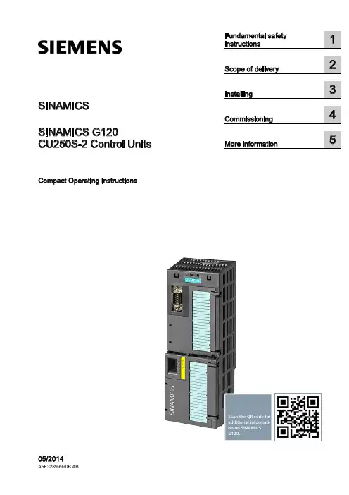
SINAMICSSINAMICS G120CU250S-2 Control UnitsCompact Operating InstructionsScan the QR code foradditional informati-on on SINAMICSG120.Siemens AG Industry Sector Postfach 48 48 A5E32899990B ABⓅ 07/2014 Subject to changeCopyright © Siemens AG 2014.All rights reservedLegal informationWarning notice systemThis manual contains notices you have to observe in order to ensure your personal safety, as well as to preventdamage to property. The notices referring to your personal safety are highlighted in the manual by a safety alertsymbol, notices referring only to property damage have no safety alert symbol. These notices shown below aregraded according to the degree of danger.DANGERindicates that death or severe personal injury will result if proper precautions are not taken.WARNINGindicates that death or severe personal injury may result if proper precautions are not taken.CAUTIONindicates that minor personal injury can result if proper precautions are not taken.NOTICEindicates that property damage can result if proper precautions are not taken.If more than one degree of danger is present, the warning notice representing the highest degree of danger willbe used. A notice warning of injury to persons with a safety alert symbol may also include a warning relating toproperty damage.Qualified PersonnelThe product/system described in this documentation may be operated only by personnel qualified for the specifictask in accordance with the relevant documentation, in particular its warning notices and safety instructions.Qualified personnel are those who, based on their training and experience, are capable of identifying risks andavoiding potential hazards when working with these products/systems.Proper use of Siemens productsNote the following:WARNINGSiemens products may only be used for the applications described in the catalog and in the relevant technicaldocumentation. If products and components from other manufacturers are used, these must be recommendedor approved by Siemens. Proper transport, storage, installation, assembly, commissioning, operation andmaintenance are required to ensure that the products operate safely and without any problems. The permissibleambient conditions must be complied with. The information in the relevant documentation must be observed. TrademarksAll names identified by ® are registered trademarks of Siemens AG. The remaining trademarks in this publicationmay be trademarks whose use by third parties for their own purposes could violate the rights of the owner. Disclaimer of LiabilityWe have reviewed the contents of this publication to ensure consistency with the hardware and softwaredescribed. Since variance cannot be precluded entirely, we cannot guarantee full consistency. However, theinformation in this publication is reviewed regularly and any necessary corrections are included in subsequenteditions.Table of contents1 Fundamental safety instructions (4)1.1 General safety instructions (4)1.2 Industrial security (5)2 Scope of delivery (6)3 Installing (7)3.1 Snapping the Control Unit onto the Power Module (7)3.2 Overview of the interfaces (8)3.3 Terminal blocks (10)3.4 Operator panels (14)4 Commissioning (15)4.1 Commissioning with STARTER (15)4.2 Connecting the inverter to the fieldbus (20)4.3 Frequently required parameters (22)5 More information (25)5.1 Manuals for your inverter (25)5.2 Product support (26)This manual describes how you install a SINAMICS G120 converter with CU250S-2 ControlUnit and commission it.What is the meaning of the symbols in the manual?An operating instruction starts here.This concludes the operating instruction.CU250S-2 Control UnitsCU250S-2 Control Units1Fundamental safety instructions1.1General safety instructionsWARNINGRisk of death if the safety instructions and remaining risks are not carefully observedIf the safety instructions and residual risks are not observed in the associated hardware documentation, accidents involving severe injuries or death can occur. • Observe the safety instructions given in the hardware documentation. • Consider the residual risks for the risk evaluation.WARNINGDanger to life or malfunctions of the machine as a result of incorrect or changed parameterizationAs a result of incorrect or changed parameterization, machines can malfunction, which in turn can lead to injuries or death.• Protect the parameterization (parameter assignments) against unauthorized access. • Respond to possible malfunctions by applying suitable measures (e.g. EMERGENCY STOP or EMERGENCY OFF).Fundamental safety instructions1.2 Industrial security 1.2Industrial securityNoteIndustrial securitySiemens provides products and solutions with industrial security functions that support thesecure operation of plants, solutions, machines, equipment and/or networks. They areimportant components in a holistic industrial security concept. With this in mind, Siemens’products and solutions undergo continuous development. Siemens recommends strongly thatyou regularly check for product updates.For the secure operation of Siemens products and solutions, it is necessary to take suitablepreventive action (e.g. cell protection concept) and integrate each component into a holistic,state-of-the-art industrial security concept. Third-party products that may be in use shouldalso be considered. For more information about industrial security, visit Hotspot-Text(/industrialsecurity).To stay informed about product updates as they occur, sign up for a product-specificnewsletter. For more information, visit Hotspot-Text ().WARNINGDanger as a result of unsafe operating states resulting from software manipulationSoftware manipulation (e.g. by viruses, Trojan horses, malware, worms) can cause unsafeoperating states to develop in your installation which can result in death, severe injuriesand/or material damage.•Keep the software up to date.You will find relevant information and newsletters at this address().•Incorporate the automation and drive components into a holistic, state-of-the-artindustrial security concept for the installation or machine.You will find further information at this address(/industrialsecurity).•Make sure that you include all installed products into the holistic industrial securityconcept.CU250S-2 Control UnitsCU250S-2 Control Units2Scope of deliveryScope of deliveryThe delivery comprises at least the following components:● A CU250S-2 Control Unit ready for operation with installed firmware.Options for upgrading and downgrading the firmware can be found on the Internet: Firmware (/WW/news/en/67364620).The fieldbus interface of the Control Unit depends on the order number. The order number, the designation and the version of the hardware (e.g. 02) and firmware (e.g. 4.6) can be found on the rating plate ① of the Control Unit. Designation Order number FieldbusCU250S-2 6SL3246-0BA22-1BA0 USS, Modbus RTU CU250S-2 DP 6SL3246-0BA22-1PA0 PROFIBUSCU250S-2 PN 6SL3246-0BA22-1FA0 PROFINET, EtherNet/IP CU250S-2 CAN6SL3246-0BA22-1CA0CANopen● Compact Operating Instructions in German and English● The inverter contains open-source software (OSS). The OSS license terms are saved in the inverter.Transferring license terms of the OSS code to a PCProcedureTo transfer the OSS license terms from the inverter to a PC, proceed as follows: 1. Switch off the inverter power supply.2. Insert an empty memory card into the card slot of the inverter. Also see Section:Overview of the interfaces (Page 8)3. Switch on the inverter power supply.4. When you have switched on the power supply, wait 30 seconds.During this time, the inverter writes the "Read_OSS.ZIP" file onto the memory card. 5. Switch off the inverter power supply. 6. Remove the card from the inverter. 7. Use a card reader and load the file to a PC.You have then transferred the OSS license terms from the inverter to a PC.CU250S-2 Control UnitsInstalling33.1Snapping the Control Unit onto the Power ModuleInstalling the Control Unit on an IP20 Power ModuleProcedureProceed as follows to connect Power Modules and Control Units:1. Locate the lugs at the rear of the Control Unit in the matching recesses of the Power Module.2. Mount the Control Unit onto the Power Module so that it audibly snaps into place.The Power Module and the Control Unit are now connected with one another.To remove the Control Unit, press on the release button on the Power Module and withdraw the Control Unit.Permissible Power ModulesYou may operate the Control Unit with the following Power Modules: ● PM240 ● PM240-2 ● PM250 ● PM260 ● PM340 1AC3.2 Overview of the interfacesCU250S-2 Control Units3.2 Overview of the interfacesTo access the interfaces at the front of the Control Unit, you must unplug the Operator Panel (if one is being used) and open the front doors.① Terminal strips ② Fieldbus interfaceSelecting the fieldbus address: • PROFIBUS • USS • Modbus RTU •CanOpen③Status LED④ USB interface for connection to a PC⑤ No function. Keep the switch in the "Vector"position. ⑥Switch for analog inputsI0/4 mA … 20 mAU-10/0 V … 10 V⑦ Connection to the operator panel ⑧Memory card slot3.2 Overview of the interfacesCU250S-2 Control UnitsInterfaces at the lower side of the Control UnitTable 3- 1 Permissible encoders on the DRIVE-CLiQ interface X100The permissible combinations of encoders for speed control and position control are listed in the "Basic Positioner" Function Manual, see also: Manuals for the Control Unit (/WW/view/en/30563628/133300).3.3 Terminal blocksCU250S-2 Control Units3.3 Terminal blocksTerminal strips behind the upper front doorDifferent reference potentials:The terminals labelled "GND" are connected internally. "GND" and "GND IN" are not connected internally.Figure 3-1Interconnection example of the digital inputs with external 24 V power supplyInterconnecting the analog inputs (terminals 3, 4 and 10, 11)For the analog inputs, you may use the internal 10 V supply (example: terminals 1 … 4, 13) or an external supply (example: terminals 10, 11).If you use the internal 10 V supply, you must connect AI 0- or AI 1- to GND.3.3 Terminal blocks Optional 24 V supply (terminals 31, 32)Connection of the optional 24 V supply has the following advantages:● The Control Unit remains in operation after disconnection of the Power Module from theline supply. The Control Unit thus maintains the fieldbus communication, for example.● You can use terminals 51 … 54 as digital outputs.Use a power supply that provides an output voltage in accordance with SELV (Safety ExtraLow Voltage) or PELV (Protective Extra Low Voltage).If you use a common external power supply for terminals 31, 32 and the digital inputs, youmust connect GND to GND IN. Terminal strips behind the lower front doorDifferent reference potentials: The reference potentials of the digital inputs are not connected internally to each other or to GND. Figure 3-2 Interconnection example of the digital inputs with external 24 V power suppliesInterconnecting the reference potential of the digital inputsTable 3- 2Supply options for the digital inputs3.3 Terminal blocksFactory setting of the terminal stripsThe factory setting of the terminals depends on the Control Unit.Control Units with USS or CANopen interfaceThe fieldbus interface is not active.Figure 3-3 Factory setting of the CU250S-2 and CU250S-2 CAN Control Units3.3 Terminal blocksControl Units with PROFIBUS or PROFINET interfaceThe function of the fieldbus interface depends on DI 3.Figure 3-4 Factory setting of the CU250S-2 DP and CU250S-2 PN Control Units3.4 Operator panelsChanging the function of the terminalsThe function of the terminals marked in color in the two figures above, can be set.In order that you do not have to successively change terminal for terminal, several terminalscan be jointly set using default settings ("p0015 Macro drive unit").The factory settings of the terminals for USS/CANopen and PROFIBUS/PROFINETdescribed above correspond to the following default settings:●p0015 = 12 (setting in STARTER: "Standard I/O with analog setpoint")●p0015 = 7 (setting in STARTER: "Fieldbus with data set switchover")Further default settings can be found in the Operating Instructions, see also: Manuals for theControl Unit (/WW/view/en/30563628/133300).Wiring the terminal strip in compliance with EMC1.If you use shielded cables, then you must connect the shield to the mounting plate of thecontrol cabinet or with the shield support of the inverter through a good electricalconnection and a large surface area.See also: EMC installation guideline(/WW/view/en/60612658)e the shield connection plate (order number 6SL3264-1EA00-0LA0) of the Control Unitas strain relief.3.4Operator panelsThe Intelligent Operator Panel (IOP) is available for snapping on to the ControlUnit or as handheld with a connection cable to the Control Unit. The graphics-capable plain text display of the IOP enables intuitive operation and diagnosticsof the inverter.See also: Compatibility of the IOP and Control Units(/WW/view/en/67273266)The BOP-2 is an operator panel for snapping on to the Control Unit. The BOP-2has a two-line display for operation and diagnostics of the inverter.Further information can be found in the Operating Instructions of the BOP-2 and the IOP: Operator Panels (/WW/view/en/30563514/133300).Commissioning4Requirements for commissioningUse one of the PC tools STARTER or Startdrive to commissionthe inverter.You can access the inverter with STARTER or Startdrive eithervia a USB connection or via the fieldbus.System requirements and download:• STARTER(/WW/view/en/26233208)• Startdrive(/WW/view/en/88851265) Help for the operation and for the functions of the commissioning tools:● STARTER videos (/mcms/mc-drives/en/low-voltage-inverter/sinamics-g120/videos/Pages/videos.aspx )● Startdrive tutorial (/WW/view/en/73598459)Commissioning with STARTER is described in the following.4.1 Commissioning with STARTERCreating a STARTER projectProcedureIn order to create a new project, proceed as follows:1. In the STARTER menu, select "Project" → "New…".2. Specify a name of your choice for the project.You have created a new STARTER project.4.1 Commissioning with STARTERTransferring inverters connected via USB to the projectProcedureProceed as follows to transfer an inverter connected via USB to your project:1.Switch on the inverter power supply.2.First insert a USB cable into your PC and then into the inverter.3.The PC operating system installs the USB driver when you are connecting the inverterand PC together for the first time.–Windows 7 installs the driver automatically.–For Windows XP you must acknowledge several system messages.4.Start the STARTER commissioning software.5.In STARTER, press the ("Accessible nodes") button.6.When the USB interface is appropriately set, then the "Accessible nodes" screen formshows the inverters that can be accessed.If you have not correctly set the USB interface, then the following "No additional nodesfound" message is displayed. In this case, follow the description below.7.Select the inverter ☑.8.Press the "Accept" button.You have transferred an inverter accessible via the USB interface into your project.4.1 Commissioning with STARTER Setting the USB interfaceProcedureProceed as follows to set the USB interface in STARTER:1.In this case set the "Access point" to "DEVICE (STARTER, Scout)" and the "PG/PCinterface" to "S7USB".2.Press the "Update" button.You have set the USB interface.STARTER now shows the inverters connected via USB.Starting the configurationProcedureTo start the configuration, proceed as follows:1.In STARTER select the drive you wish to commission.2.Start the wizard for the device configuration:You have started the configuration.4.1 Commissioning with STARTERPerforming the configurationFollow the steps of the configuration wizard and enter the data ofyour application.Loading the configured data into the driveProcedureProceed as follows to load the configured data into the drive:1. Select your project and go online: .2. STARTER compares your configuration with the real inverter. STARTER signals anydifferences in the "Online/offline comparison".Acknowledge the message by pressing the "Load HW configuration to PG" button.3. Open "Drive Navigator".4. Select the "Commissioning" button.5.Click on "Load data to the drive".6. ☑ In the screen form, select "After loading copy RAM to ROM".7. Load your configuration into the inverter.8. Close the "Commissioning" screen form.You have loaded your configuration into the drive and therefore performed the basiccommissioning.Identifying motor dataRequirements● In the basic commissioning, you have selected the motor identification (MOT ID). In thiscase, after the basic commissioning has been completed, the inverter issues the alarmA07991.● The motor has cooled down to the ambient temperature.If the motor is too hot, the motor data identification will provide incorrect values and thevector control will become unstable.4.1 Commissioning with STARTERDANGERRisk of injury or material damage as a result of machine movements when switching on themotorSwitching on the motor for identification purposes may result in hazardous machinemovements.Secure dangerous machine parts before starting motor data identification:•Before switching on, check that no parts are loose on the machine or can be spun out.•Before switching on, ensure that nobody is working on the machine or located within its working area.•Secure the machine's work area against unintended access.•Lower hanging/suspended loads to the floor.ProcedureTo initiate motor data identification and optimizationof the motor control, proceed as follows:1.Open by double-clicking on the control panel inSTARTER.2.Assume master control for the inverter.3.Set the "Enable signals"4.Switch on the motor.The inverter starts the motor data identification.This measurement can take several minutes.After the measurement, the inverter switches offthe motor.5.Relinquish the master control after the motor dataidentification.6.Click the Save (RAM to ROM) button.You have now completed motor data identification.Self-optimization of the closed-loop controlIf you have also selected a rotating measurement with self-optimization of the vector controlin addition to the motor data identification, then you must switch on the motor again asdescribed above and wait for the optimization run to be completed.4.2 Connecting the inverter to the fieldbus4.2Connecting the inverter to the fieldbusWhere can I find instructions for the fieldbus connection of the inverter?You can find instructions for the fieldbus connection on the Internet:●Application examples (/WW/view/en/60733299)●Operating Instructions, "Inverter with CU250S-2 Control Units": Manuals for the ControlUnit (/WW/view/en/30563628/133300)●Function Manual, "Fieldbusses": Manuals for the Control Unit(/WW/view/en/30563628/133300)Example telegramThe inverter telegrams without configured basic positioner are described in the OperatingInstructions and in the "Communications" Function Manual: Manuals for the Control Unit(/WW/view/en/30563628/133300)The telegrams with configured basic positioner are described in the "Basic Positioner andTechnology" Function Manual: Manuals for the Control Unit(/WW/view/en/30563628/133300).Control word 1 (STW1)4.2 Connecting the inverter to the fieldbusStatus word 1 (ZSW1)4.3 Frequently required parametersDescription files for fieldbusesThe description files are electronic device data sheets which contain all the requiredinformation of a higher-level controller. You can configure and operate the inverter on afieldbus with the appropriate description file.4.3Frequently required parameters4.3 Frequently required parameters4.3 Frequently required parametersMore information 5 5.1Manuals for your inverterDocumentation on DVDSINAMICS Manual Collection, order number 6SL3097-4CA00-0YG0Table 5- 1 Manuals for your inverter for downloadMore information5.2 Product support5.2Product support Table 5- 2 Technical support。


制导雷达SITRANS LG250四线制 Modbus两腔式转换器棒型和绳型探头操作说明书 • 09/20172PBD-51041254SITRANS LG250 - 操作说明书44280-ZH-1710303PBD-51041254SITRANS LG250 - 操作说明书44280-Z H -171030目录1关于本文献资料 ............................................................................................................................................51.1 功能 .............................................................................................................................................................................51.2 对象 .............................................................................................................................................................................51.3 使用的标记.. (52)为了您的安全 ...............................................................................................................................................62.1 获得授权的人员.........................................................................................................................................................62.2 合规使用 .....................................................................................................................................................................62.3 谨防错误使用.............................................................................................................................................................62.4 一般安全提示.............................................................................................................................................................62.5 欧盟一致性.................................................................................................................................................................62.6 NAMUR 推荐 ............................................................................................................................................................62.7 在美国和加拿大进行安装和运行. (73)产品说明 ......................................................................................................................................................83.1 结构 .............................................................................................................................................................................83.2 作业方式 .....................................................................................................................................................................93.3 包装、运输和仓储 ..................................................................................................................................................103.4 附件与备件 (114)安装 ...........................................................................................................................................................134.1 一般提示 ...................................................................................................................................................................134.2 安装提示 . (135)与供电电源和总线系统相连接 .....................................................................................................................215.1 准备接线 ...................................................................................................................................................................215.2 连接 ...........................................................................................................................................................................215.3 接线图 .......................................................................................................................................................................235.4 附加电子部件...........................................................................................................................................................245.5 启动阶段 . (246)对带有显示和调整模块的传感器进行调试 ...................................................................................................256.1 操作范围 ...................................................................................................................................................................256.2 使用显示和调整模块 ..............................................................................................................................................256.3 操作系统 ...................................................................................................................................................................266.4 参数化 - 快速调试 ..................................................................................................................................................276.5 参数化 - 扩展了的操作功能..................................................................................................................................276.6 对设置的参数数据的存储 .. (427)将传感器和 Modbus 接口连同 PACTware 一起投入使用 ..........................................................................437.1 连接计算机...............................................................................................................................................................437.2 通过 PACTware 设置参数.....................................................................................................................................447.3 设置仪表地址...........................................................................................................................................................457.4 通过快速调试来投入使用 ......................................................................................................................................467.5 对设置的参数数据的存储 .. (478)诊断与服务 .................................................................................................................................................488.1 维护 ...........................................................................................................................................................................488.2 诊断储存器...............................................................................................................................................................488.3 状态信息 ...................................................................................................................................................................488.4 排除故障 ...................................................................................................................................................................518.5 更换电子插件...........................................................................................................................................................538.6 更换测量绳/测量棒.................................................................................................................................................548.7 软件升级 ...................................................................................................................................................................568.8 需要维修时的步骤 .. (569)拆卸 ...........................................................................................................................................................579.1 拆卸步骤 ...................................................................................................................................................................579.2 废物清除 . (57)4PBD-51041254SITRANS LG250 - 操作说明书44280-ZH-17103010 附件 (58)10.1 技术参数 ...................................................................................................................................................................5810.2 Modbus 的依据......................................................................................................................................................6910.3 Modbus 寄存器......................................................................................................................................................7110.4 Modbus RTU 指令 ................................................................................................................................................7310.5 Levelmaster 指令 ..................................................................................................................................................7610.6 典型的 Modbus 主机的配置................................................................................................................................8010.7 尺寸 ...........................................................................................................................................................................8510.8 商标 (89)用于防爆区域的安全提示请在将仪表用于防爆应用领域时遵守专门针对防爆的安全说明。