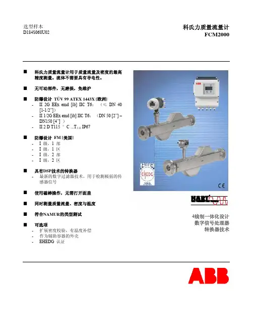
FCM2000质量流量计中文手册(V 0.7)
- 格式:pdf
- 大小:5.29 MB
- 文档页数:51
FCM-IV流量测控仪使用说明书上海煤科实业有限公司Shanghai Coal Science & Technique Industrial Co. Ltd.请您仔细阅读该说明书,以便正确使用仪表。
1概述FCM-IV型流量测控仪可与任何具有脉冲输出的流量传感器(变送器)配套使用,其特点如下:1.1同时显示瞬时流量和累积流量;1.2准确地进行流量定量控制;1.3四路继电器触点输出;1.4历史报警记录查询;1.5定时或随时打印累积流量和瞬时流量;1.6可提供直流电流或电压输出,与调节系统联用可实现流量的自动控制;1.7测量数据断电保存;1.8时钟功能;本仪表与相应的传感器(变送器)配套使用,可广泛应用于石油、化工、食品、船舶等行业中对管道液体流量进行测量,以及液压机械、液压试验设备中流体流量的在线检测与控制。
2主要技术参数2.1误差:累积流量基本误差:≤0.1% FS ± 1字瞬时流量基本误差:≤0.3% FS ± 1字定量控制基本误差:≤0.1% FS ± 1字2.2显示范围:累积流量: 0.000~9,999,999L(T)瞬时流量:四位数码管显示,0.000~9999L/min(T/h)2.3输入信号:正弦波或方波,幅值:5V~24V,频率1~10,000Hz2.4输出信号:模拟量输出: 4~20mA (≤800Ω)或 1~5V (≤30 mA)精度 1%开关量输出:继电器触点输出(AC220V/0.1A,DC24V/1A,阻性负载)馈电输出: DC5V或12V (≤30 mA)通讯: RS-2322.5打印:直接配串行TP微型打印机,通讯方式为RS-2322.6报警方式:可选择继电器上、下限报警输出,LED报警指示2.7流量定量控制方式: ON/OFF带回差,可设置流量定量控制值,由继电器触点输出,启、停阀或泵2.8通讯方式:双向RS-232口2.9设定方式:面板轻触式按键数字设定,设定值断电永久保存2.10保护方式:断电累积流量值保持大于一年2.11工作条件:环境温度:0~40℃,相对湿度:≤85%2.12电源: 220V±10%AC2.13尺寸:外形尺寸: 160×80×140(mm)(宽×高×深)开孔尺寸: 152×76 (mm)(宽×高)3 工作原理(见图1)流量传感器发出的脉冲信号fin,经滤波整形后,送入单片机计数器,进行数据采集,然后在七位数码管上显示累积流量,在四位数码管上显示瞬时流量,并且输出表示瞬时流量的4~20mA 电流值。
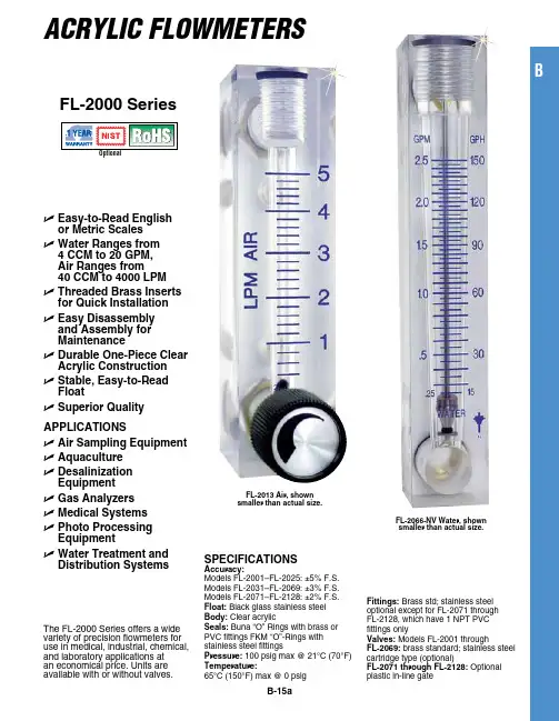
The FL-2000 Series offers a wide variety of precision flowmeters for use in medical, industrial, chemical, and laboratory applications at an economical price. Units are available with or without valves.Acrylic FlowmetersB-15aFL-2000 SeriesSpeciFicationSaccuracy:Models FL-2001–FL-2025: ±5% F.S. Models FL-2031–FL-2069: ±3% F.S. Models FL-2071–FL-2128: ±2% F.S.Float: Black glass stainless steel Body: Clear acrylicSeals: Buna “O” Rings with brass or PVC fittings FKM “O”-Rings with stainless steel fittingspressure: 100 psig max @ 21°C (70°F)temperature:65°C (150°F) max @ 0 psigFittings: Brass std; stainless steel optional except for FL-2071 through FL-2128, which have 1 NPT PVC fittings onlyValves: Models FL-2001 throughFL-2069: brass standard; stainless steel cartridge type (optional)FL-2071 through FL-2128: Optional plastic in-line gateU e asy-to-Read english or Metric Scales U W ater Ranges from 4 ccM to 20 GpM, air Ranges from 40 ccM to 4000 LpM U t hreaded Brass inserts for Quick installation U e asy Disassembly and assembly for Maintenance U D urable one-piece clear acrylic construction U S table, easy-to-Read Float U S uperior Quality appLicationS U a ir Sampling equipment U a quaculture U D esalinization equipment U G as analyzers U M edical Systems U p hoto processing equipment U W ater treatment andDistribution SystemsFL-2013 air, shownsmaller than actual size.FL-2066-nV Water, shownsmaller than actual size.B(13.5)B-15bFL-2091 through FL-2128 DimensionsFL-2097, shown smaller than actual sizeTo order with plastic integral gate valve, add suffix “-V” to model number for additional cost for FL-2090 Series, and FL-2120 Series.For optional 10-point NIST certificate add suffix, “-NIST” to the model number, for additional cost and two weeks to the standard lead time.Ordering Example: FL-2095, flow meter , 100 to 1400 LPM Air FL-2127-V, flow meter , 4 to 36 LPM water, with valves.Units are standard without valves.To order with plastic integral gate valve, add suffix “-V” to model number for additional cost.For optional 10-point NIST certificate add suffix, “-NIST” to the model number for additional cost and two weeks to the standard lead time.Ordering Examples: FL-2075, flow meter valve, 100 to 1400 LPM air.FL-2080, flow meter valve, 2 to 19 LPM water.FL-2041-nV, shown smaller than actual size.FL-2053, Water,shown smaller thanactual size.FL-2066-nV, shown smaller than actual size.To order with stainless steel valve, add suffix “-SS” to model number for additional cost.To order without a valve, add suffix “-NV” to model number and subtract from cost.For optional 10-point NIST certificate add suffix, “-NIST” to the model number, for additional cost and two weeks to the standard lead time.Ordering Examples: FL-2036, economical flow meter , with brass valve, 14 to 150 SCFH Air.FL-2036-NV , economical flow meter ,without brass valve,14 to 150 SCFH Air.BFL-2060, air, shown smaller than actual size.Dual scales supplied std: SCFM/SCFH, GPM/GPH and LPM/LPH To order with stainless steel valve, add suffix “-SS” to model number for additional cost.To order without a valve, add suffix “-NV” to model number and subtract from cost.For optional 10-point NIST certificate add suffix, “-NIST” to the model number, for additional cost and two weeks to the standard lead time.Ordering Examples: FL-2060, flow meter with brass valve, 0.5 to 5 SCFM. FL-2069-NV , flow meter no valve 2 to 20 LPM.FL-2091, air, shown smaller thanactual size.B-15cFL-2021-nV, Water, shown larger than actual size.Units come standard with brass valves and operator’s manual.To order with stainless steel valves, add suffix “-SS” to model number for additional cost. To order without a valve, add suffix “-NV” to model number and subtract from cost.For optional 10-point NIST certificate add suffix, “-NIST” to the model number, for additional cost and two weeks to the standard lead time.Ordering Examples: FL-2005, economical flow meter with brass valve, 2 to 20 SCFH air. FL-2005-NV , economical flow meter without valve, 2 to 20 SCFH air.accuracy: ±5% Full Scale panel MountB-15d。

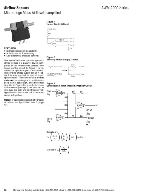
681-800-537-6945 USA 1-815-235-6847 International1-800-737-3360 CanadaFEATURESɀBidirectional sensing capability ɀActual mass air flow sensingɀLow differential pressure sensing The AWM2000 Series microbridge mass airflow sensor is a passive device com-prised of two Wheatstone bridges. The heater control circuit in Figure 1is re-quired for operation per specifications.The sensing bridge supply circuit in Fig-ure 2 is also required for operation per specifications. These two circuits are not on board the package and must be sup-plied in the application. The differential amplifier in Figure 3 is a useful interface for the sensing bridge. It can be used to introduce the gain and to introduce volt-age offsets to the sensor output as refer-enced in Equation 1.Note: For applications sensing hydrogen or helium, see Application Note 3, page 131.Figure 1Heater Control CircuitFigure 2Sensing Bridge Supply CircuitFigure 3Differential Instrumentation Amplifier CircuitEquation 1:V o ⍧2R 2+R 1R 4V 2-V 1+V offset()()()R 1R 3where V offset ⍧V S()R 6R 6+R 51-800-537-6945 USA 1-815-235-6847 International 1-800-737-3360 Canada 691. Output Voltage is ratiometric to supply voltage.2. Temperature shifts when sensing differential pressure correlates to the density change of the gas over temperature.See Application Note 1.3. Maximum allowable rate of flow change to prevent damage: 5.0 SLPM/1.0 sec.MOUNTING DIMENSIONS (for reference only)Airflow701-800-537-6945 USA 1-815-235-6847 International 1-800-737-3360 CanadaOUTPUT FLOW VS INTERCHANGEABILITY (Note 1)Performance Characteristics @10.0 ±0.01VDC, 25°C AWM2100V AWM2150VAWM2200V(Note 2)AWM2300V Press.Flow Nom.Tol.Press.Flow Nom.Tol.Flow Press.Nom.Tol.Press.Flow Nom.Tol.mBar sccm mV±mVȖBar sccm mV±mVsccm ⍯H 2O mV±mVmBar sccm mV±mV0.4920044.50 4.25533014.0 2.5120 4.0031.75 3.50 3.4100055.50 3.700.3515038.75 3.0036209.5 1.590 3.0026.75 2.50 2.480052.90 3.500.2110030.00 1.501710 5.0 1.560 2.0020.00 1.20 1.865050.00 2.500.095016.50 2.509.85 2.5 1.030 1.0011.20 1.800.8340042.50 3.000.000.00 1.007.44 2.0 1.000.000.001.000.3120029.20 3.20−0.09−50−16.50 4.50 6.23 1.5 1.0−30−1.00−11.20 3.0000.00 1.00−0.21−100−30.00 5.0052 1.0 1.0−60−2.00−20.00 3.30−0.31−200−28.9015.00−0.35−150−38.807.65 2.510.50.8−90−3.00−26.75 5.30−0.83−400−41.2026.00−0.49−200−44.509.75000.00.6−120−4.00−31.757.00−1.6−600−48.2029.50−9.8−5−2.5 2.0−2.4−800−52.2032.50−53−30−14.05.0−3.4−1000−55.0036.00Notes:1.Numbers in BOLD type indicate calibration type, mass flow or differential pressure.Tolerance values apply to calibration type only.2.Differential pressure calibrated devices are not recommended for flow e flow calibrated devices for flow measurement.OUTPUT CURVES。
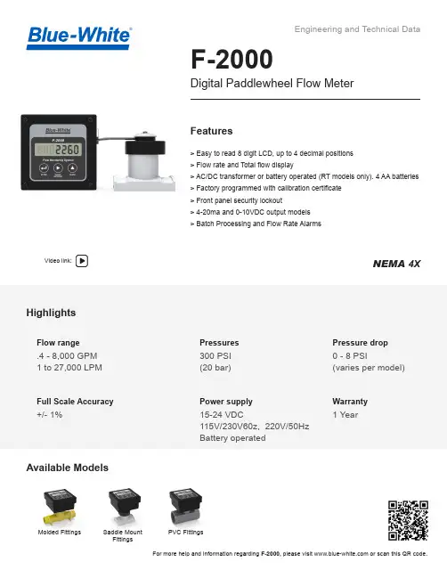
Video link:NEMA 4XFor more help and information regarding F-2000, please visit or scan this QR code.F-2000Digital Paddlewheel Flow Meter> Easy to read 8 digit LCD, up to 4 decimal positions > Flow rate and Total flow display> AC/DC transformer or battery operated (RT models only). 4 AA batteries > Factory programmed with calibration certificate > Front panel security lockout> 4-20ma and 0-10VDC output models > Batch Processing and Flow Rate Alarms®HighlightsFlow rangeFull Scale Accuracy Power supply .4 - 8,000 GPM 1 to 27,000 LPM Pressures300 PSI (20 bar)Pressure dropWarranty0 - 8 PSI(varies per model)+/- 1%15-24 VDC115V/230V60z, 220V/50Hz Battery operated1 YearFeaturesMolded FittingsSaddle Mount FittingsPVC FittingsAvailable Models2Engineering SpecificationsDigital Paddlewheel Flow MeterPerformanceDimensionsF-2000Saddle FittingsPipe Size A B 1-1/2”(50mm)4-1/2” 3-3/16” 2”(63mm)4-1/2”3-3/16”3”(90mm)4-1/2”3-3/16”4”(110mm)4-1/2”3-3/16”6”(160mm)4-3/8”3-3/16”8”(200mm)4-3/8”3-3/16”10”(250mm)4-1/2”4-1/2”12”(315mm)4-1/2”4-1/2”Molded FittingsPipe Size A B 3/8”3-3/4” (95)4-3/4” (121)1/2”3-3/4” (95)5-1/8” (130)3/4”4” (102)5-1/4” (133)1”4” (102)5-5/8” (143)1-1/2”4-1/2” (114)6-1/2” (165)2”4-3/4” (121)6-3/4” (171)Pipe SizeA B 1”6”4”1-1/2”6-5/8”4-1/2”2”7-1/8”4-3/4”PVC Saddles & PVC TeesPVDF Saddles & SS TeesSTATIC PRESSURE PSI(BAR)Maximum Working Pressure300 PSI (20 bar) @ 70 °F (21 °C)Maximum Fluid Temperature 200 °F (93 °C) @ 0 PSI (PVDF saddles and PP Molded fittings)140 °F (60 °C) @ 0 PSI (PVC saddles and PVC Tee fittings)NOTE: Temperature rating of F-2000 only. Actual pipe rating mary vary.Maximum Ambient Temperature 14 °F to 110 °F/ -10 °C to 43 °C Maximum Pressure Drop up to 8 PSI (varies per model)Full Scale Accuracy +/- 1%Power Requirement15 VDC Nominal (15 - 24 VDC Absolute)Model RT units only 4 AA batteries or 15 - 24 VDC plug-in transformer All units 15 - 24 VDC (plug-in transformer supplied)Signal Distance AC sine wave sensor = 200 ft(60 m)Optional Hall Effect sensor = 1 mile(1.6 km)Signal Cable3 conductor shielded. Included 25 ft(7.6 m)(Option for 50 ft and 100 ft)Approximate Shipping Weight4 lb. (1.8 kg)Enclosure NEMA 4X (IP56)RoHS CompliantYesPP3Materials of ConstructionF-2000Ordering InformationMolded In-Line Pipe FittingsTEE Pipe FittingsSaddle Mount Pipe FittingsPipe Size GPM Flow Range LPM Flow Range M 3/HR Flow Range OZ/MinFlow RangeModel Number M/NPTMNPT MBSPT 3/8".8 to 830 - 300.2 - 1.8106 - 105838M138MB13/8”.4 to 4 1 - 100.1 - 0.635 - 35338M238MB21/2" 2 to 207 - 700.4 - 4.2247 - 246950M150MB13/4" 3 -3011 - 1100.7 - 6.6388 - 388075M175MB11" 5 to 5020 - 200 1.2 - 12705 - 705410M110MB11-1/2" 6 to 6025 - 2501.5 - 15885 - 881815M215MB22”10 to 10040 - 400 2.4 - 241411 - 1410820M320MB32”20 to 20070 - 7004.2 - 422469 - 2468920M420MB4Pipe Size IPSGPM Range M 3/HR Flow Range Model Number Sch 40Sch 801-1/2"15 - 150 3.5 - 34.515K415K8315mm2700 - 27000162 - 162031A0Pipe SizeGPM Range LPM Range Model NumberSolvent Weld PVC Tee1" 6 to 6025 - 25010AT 1-1/2"15 to 15060 - 60015AT 2"30 to 300100 - 100020AT 3"60 to 600230 - 230030ATSaddle material:PVDF ( 1-1/2”, 2”, 3”, 50mm, 63mm, 90mm sizes) PVC (other sizes)In-Line Molded Tee: Polypropylene Sensor, paddlewheel, axle: PVDFSensor O-ring seals:Viton (optional EP)TDS# 85000-171 REV 4202306195300 Business Drive, Huntington Beach, CA 92649TEL714-893-8529|FAX714-894-9492||********************F-2000 Model Number MatrixF-20005300 Business Drive, Huntington Beach, CA 92649 TEL714-893-8529|FAX714-894-9492||********************VariationsRT = Flow Rate and TotalizingAO = Analog Output, Flow Rate and Totalizing PC = Batch Processing, Flow Rate Alarm, Proportional Metering, Flow Rate and TotalizingAP = Analog Output, Batch Processing, Flow Rate Alarm Proportional Metering, Flow Rate Alarm and Flow Totalizing FC = Flow Sensor - AC Coil - 200 ft. range FH = Flow Sensor - Hall Effect - 1 mile rangePipe Sizes M/NPTImperial Pipe Sizes Metric Pipe Sizes 38 = 3/8" IPS 05 = 50mm 50 = 1/2" IPS 06 = 63mm 75 = 3/4" IPS 07 = 75mm 10 = 1" IPS 09 = 90mm 15 = 1-1/2" IPS 11 = 110mm 20 = 2" IPS 16 = 160mm 25 = 2-1/2" IPS 20 = 200mm30 = 3" IPS 25 = 250mm (PN10 only)40 = 4" IPS 31 = 315mm (PN10 only)60 = 6" IPS 80 = 8" IPS 100 = 10" IPS 120 = 12" IPSSaddle Pipe Fitting TypeSADDLE, SCH40 (I.P.S.) PVC or IRON pipeK4 = 1-1/2", 2", 3" PVDF A4 = 2-1/2”, 4”, 6”, 8” PVC A4 = 10”, 12” PVC SADDLE, SCH80 (I.P.S.) PVC pipeK8 = 1-1/2", 2", 3" PVDF A8 = 2-1/2”, 4”, 6”, 8” PVC A8 = 10”, 12” PVC SADDLE, PN10 METRIC (DIN 8062) pipeK0 = 50mm, 63mm, 90mm PVDF A0 = 75, 110, 160, 200 PVC A0 = 250,315mm PVC SADDLE, PN16 METRIC (DIN 8062) pipeK6 = 50mm, 63mm, 90mm PVDF A6 = 75, 110, 160, and 200, PVCInline Pipe Fitting TypeINLINE INJECTION MOLDED PP AMERICAN M/NPTM1 = Range #1, M2 = Range #2M3 = Range #3, M4 = Range #43/8", 1/2", 3/4", 1" M/NPT polypropylene 1-1/2" M/NPT polypropylene 2" M/NPT polypropylene INLINE INJECTION MOLDED PP BRITISH M/BSPTMB1 = Range #1, MB2 = Range #2MB3 = Range #3, MB4 = Range #43/8", 1/2", 3/4", 1" M/BSPT polypropylene 1-1/2" M/BSPT polypropylene 2" M/BSPT polypropylene INLINE INJECTION MOLDED TEE PVC SLIP/SOCKETAT = 1", 1-1/2", 2" Female slip glue/weld 3” Female slip glue/weldCalibration UnitsGM = U.S. Gallons per minute LH = Liters per hour GH = U.S. Gallons per hour LD = Liters per dayGD = U.S. Gallons per day MH = Cubic Meters per hour OM = U.S. Ounces per minute IM = Imperial Gallons per minute AD = Acre Feet per day IH = imperial Gallons per hourLM = Liters per minuteCalibration Range (see pipe fitting detail)1 = Range 13 = Range 32 = Range 24 = Range 4Display MountingS = Meter Mounted on AC Coil Sensor P = Meter Panel Mounted, AC Coil Sensor, 200 ft. range, includes 25 Ft. of cable H = Meter Panel Mounted, Hall Effect Sensor, 1 mile Range, includes 25 ft. of cable X = Sensor only (without Display Meter)PowerB = Battery Holder with 4 AA cells1 = U.S. Transformer, AC 115V60Hz/15Vdc, NEMA 5/15 plug2 = Europe Transformer, AC 230V50Hz/15Vdc, CEE 7/VII plug3 = U.S. Transformer, AC 230V60Hz/15Vdc, NEMA5/15 plug X = No Selection (Customer must supply power)OptionP = No pipe fitting*50FT = 50 feet of signal cable 100FT = 100 feet of signal cableRTSB38M1GM1-PSample Model NumberOptional Accessories and Components 71000-294 Panel Mount Kit Bracket71000-514 Mounting Conversion Kit, Sensor Mount to Panel Mount.71000-301 Wall Mount Adapter Kit. Cable Not Inlcuded.71000-302 Wall or Pipe Mounting Kit (3/8” - 1.5 “ Pipe). Cable Not Included.71000-303 Wall or Pipe Mounting Kit (2” Pipe). Cable Not Included. 71000-304 Wall or Pipe Mounting Kit (3” Pipe). Cable Not Included. 71000-305 Wall or Pipe Mounting Kit (4” Pipe). Cable Not Included. 71000-306 Wall or Pipe Mounting Kit (6” Pipe). Cable Not Included. 71000-307 Wall or Pipe Mounting Kit (8” Pipe). Cable Not Included. 71000-414 Wall or Pipe Mounting Kit (10” Pipe). Cable Not Included. 71000-415 Wall or Pipe Mounting Kit (12” Pipe). Cable Not Included. 71000-322 Battery Back-up KitSee Spare Parts or Instruction Manual for more options.。
附件1报警,警告和故障码如果有报警发生的情况下,当选中报警页后,会显示报警、警告和故障码。
在报警发生和被复位的时间和日期的下边,会以清单的方式列出报警的功能码。
在下列项中的N将表示所测的管路编号,1,2或者是3。
●非责任报警的参数符号qN low未修正的流量值低于Lo qNpresN High压力值高于PressureN High的值。
presN Low 压力值低于PressureN Low的值。
tempN High 温度值高于T emperatureN High的值。
tempN Low 温度值低于T emperatrueN Low的值。
只对涡轮流量计turbN lf如果有涡轮流量计报警发生(叶轮故障)(低频)只对涡轮流量计usN eff.1% 1声道的发射效率低于预设的%限制usN eff.2% 2声道的发射效率低于预设的%限制usN eff.3% 3声道的发射效率低于预设的%限制usN eff.4% 4声道的发射效率低于预设的%限制usN eff.5% 5声道的发射效率低于预设的%限制●责任报警的参数符号presN max 压力高于pressureN max的值presN min 压力低于pressureN min的值presN df. 正在使用的压力值是默认值pressureN dfPresN hart 流量计算机和压力变送器通讯失败,或者是压力变送器处在报警状态tempN max温度高于temperatureN max的值tempN min 温度低于temperatureN min的值tempN df. 正在使用的温度值是默认值pressureN dfT empN hart流量计算机和温度变送器通讯失败,或者是温度变送器处在报警状态qN high未修正的流量值高于HiN q. 的值超过1分钟znN high基准的压缩因子超出允许的znN high值znN low基准的压缩因子超出允许的znN low值只对涡轮流量计turbN hf如果有涡轮流量计报警发生(叶轮故障)(高频)只对涡轮流量计usN paths 声道号定义错误usN secur流量计的安全报警位被设置usN level1 精度减小报警usN level2 精度减小报警usN comms 在最近的5秒钟内没有一个有效的通讯信号●温度报警tempN alrm温度低于t-alarm的值,并且qb高于Lo.q超过1小时在下列项中的X将表示接、插板槽的编号1,2,3,4或者是5。
Main Totals总累计量页面+Vb1工况总累计量+Vn1标况总累计量+E1 能量总累计量+M1 质量总累计量Current Hour n-acc 当前小时总累计量页面+Vb.ch.na1工况当前小时累积量+Vn.ch.na1标况当前小时累积量+E.ch.na1 能量当前小时总累计量+M.ch.na1 质量当前小时总累计量Current Day n-acc 当前天总累计量页面+Vb.cd.na1工况当前天累积量+Vn.cd.na1标况当前天累积量+E.cd.na1 能量当前天总累计量+M.cd.na1 质量当前天总累计量Current Month n-acc 当前月总累计量页面+Vb.cm.na1工况当前月累积量+Vn.cm.na1标况当前月累积量+E.cm.na1 能量当前月总累计量+M.cm.na1 质量当前月总累计量Previous Hour n-acc 前一小时总累计量页面+Vb.Ph.na1工况前一小时累积量+Vn.Ph.na1标况前一小时累积量+E.Ph.na1 能量前一小时总累计量+M.Ph.na1 质量前一小时总累计量Previous Day n-acc 前一天总累计量页面+Vb.Pd.na1工况前一天累积量+Vn.Pd.na1标况前一天累积量+E.Pd.na1 能量前一天总累计量+M.Pd.na1 质量前一天总累计量Previous Month n-acc 前一月总累计量页面+Vb.Pm.na1工况前一月累积量+Vn.Pm.na1标况前一月累积量+E.Pm.na1 能量前一月总累计量+M.Pm.na1 质量前一月总累计量Line Condition>>>GeneralLine Condition工况QLine.1工况瞬时流量Qn.1标况瞬时流量ed.1压力在用值ed.1温度在用值Calculations 压缩因子计算Zn.1标况压缩因子Z.1工况压缩因子K.1压缩系数CFV.1放大系数VOS Diagnostic 声速核查Spd of Sound.1 测量声速dSOS.1 理论声速Gas vel.1 气体流速Line Condition>>>Stream1Hourly Flow Rates小时瞬时流量QLine.1工况瞬时流量Qn.1标况瞬时流量qE.1能量瞬时流量qM.1质量瞬时流量Daily Flow Rates瞬时流量以天计Flow Rate Per Second瞬时流量以秒计Presure压力Pres.sens1.1压力变送器数值Pres.keypad.1压力替代值ed.1压力在用值Temperature温度Temp.sens1.1温度变送器数值Temp.keypad.1温度替代值ed.1温度在用值Z Factor 压缩因子计算Zn.1标况压缩因子Z.1工况压缩因子K.1压缩系数CFV.1放大系数Ultrasonic Data超声波数据Num Path.1超声波通道数4个通道Samp.Rate.1采样率(10~15正常)Spd of Sound.1测量声速Gas vel.1气体流速Meter Type.1流量计型号Ultrasonic Path 1超声波通道1 Valsamples1.1 采样率(10~15正常)Efficiency 1.1效率因子(80%以上)Cpp 1.1测量声速Vpp 1.1气体流速Agclevel_A 1.1探头A电压增益Agclevel_B 1.1探头B电压增益Agclimit_A 1.1探头A电压增益上限Agclimit_B 1.1探头B电压增益上限Ultrasonic Path 2超声波通道2以下以此类推Gas Data>>>Preset 预设值、替代值Received接收值Used 在用值Edit 编辑模式—密码11111、改组分替代值Edit—1111—Stream1—Gas Dataa上下键挪动光标到要改的组分上,并按回车b输入所改的组分值,并按回车c重复a和b直到把所有组分更改完毕d按F4键,选择Exit,选择Exit & Save,完毕。


FLK-2000 SeriesAcrylic Variable Area Flow Meters, Air or Water Model Numbers FLK-2201 – FLK-2224Model Media Range AccuracySize: in.(mm)A B C D E FFLK-2201 Air 0.2 to 2 SCFH Air ±4%4.02in.(102mm)1.18in.(30mm)0.98in.(25mm)0.79in.(20mm)1/8NPT3.03in.(77mm)FLK-2202 Air 0.2 to 3 SCFH Air ±4%4.02in.(102mm)1.18in.(30mm)0.98in.(25mm)0.79in.(20mm)1/8NPT3.03in.(77mm)FLK-2203 Air 0.85 to 8.5 SCFH Air ±4%4.02in.(102mm)1.18in.(30mm)0.98in.(25mm)0.79in.(20mm)1/8NPT3.03in.(77mm)FLK-2205 Air 2.5 to 25 SCFH Air ±4%4.02in.(102mm)1.18in.(30mm)0.98in.(25mm)0.79in.(20mm)1/8NPT3.03in.(77mm)FLK-2206 Air 4 to 40 SCFH Air ±4%4.02in.(102mm)1.18in.(30mm)0.98in.(25mm)0.79in.(20mm)1/8NPT3.03in.(77mm)FLK-2208 Air 12 to 50 SCFH Air ±4%4.02in.(102mm)1.18in.(30mm)0.98in.(25mm)0.79in.(20mm)1/8NPT3.03in.(77mm)FLK-2209 Air 25 to 200 SCFH Air ±4%4.02in.(102mm)1.18in.(30mm)0.98in.(25mm)0.79in.(20mm)1/8NPT3.03in.(77mm)FLK-2211 Air 0.1 to 1 LPM Air ±4%4.02in.(102mm)1.18in.(30mm)0.98in.(25mm)0.79in.(20mm)1/8NPT3.03in.(77mm)FLK-2212 Air 0.3 to 3 LPM Air ±4%4.02in.(102mm)1.18in.(30mm)0.98in.(25mm)0.79in.(20mm)1/8NPT3.03in.(77mm)M0702/1121Model Numbers FLK-2232 – FLK-2264***********************Servicing North America:U.S.A. Omega Engineering, Inc.Headquarters: 800 Connecticut Ave, Suite 5N01, Norwalk, CT 06854Toll-Free: 1-800-826-6342 (USA & Canada only)Customer Service: 1-800-622-2378 (USA & Canada only)Engineering Service: 1-800-872-9436 (USA & Canada only)Tel: (203) 359-1660 Fax: (203) 359-7700e-mail:**************For Other Locations Visit /worldwideThe information contained in this document is believed to be correct, but OMEGA accepts no liability for any errors it contains, and reserves the right to alter specifications without notice.WARNING: These products are not designed for use in, and should not be used for, human applications.WARRANTY/DISCLAIMEROMEGA ENGINEERING, INC. warrants this unit to be free of defects in materials and workmanship for a period of 13 months from date of purchase. OMEGA’s WARRANTY adds an additional one (1) month grace period to the normal one (1) year product warranty to cover handling and shipping time. This ensures that OMEGA’s customers receive maximum coverage on each product.If the unit malfunctions, it must be returned to the factory for evaluation. OMEGA’s Customer Service Department will issue an Authorized Return (AR) number immediately upon phone or written request. Upon examination by OMEGA, if the unit is found to be defective, it will be repaired or replaced at no charge. OMEGA’s WARRANTY does not apply to defects resulting from any action of the purchaser, including but not limited to mishandling, improper interfacing, operation outside of design limits, improper repair, or unauthorized modification. This WARRANTY is VOID if the unit shows evidence of having been tampered with or shows evidence of having been damaged as a result of excessive corrosion; or current, heat, moisture or vibration; improper specification; misapplication; misuse or other operating conditions outside of OMEGA’s control. Components in which wear is not warranted, include but are n ot limited to contact points, fuses, and triacs.OMEGA is pleased to offer suggestions on the use of its various products. However, OMEGA neither assumes responsibility for any omissions or errors nor assumes liability for any damages that result from the use of its products in accordance with information provided by OMEGA, either verbal or written. O MEGA warrants only that the parts manufactured by the company will be as specified and free of defects. OMEGA MAKES NO OTHER WARRANTIES OR REPRESENTATIONS OF ANY KIND WHATSOEVER, EXPRESSED OR IMPLIED, EXCEPT THAT OF TITLE, AND ALL IMPLIED WARRANTIES INCLUDING ANY WARRANTY OF MERCHANTABILITY AND FITNESS FOR A PARTICULAR PURPOSE ARE HEREBYDISCLAIMED. LIMITATION OF LIABILITY: The remedies of purchaser set forth herein are exclusive, and the total liability of OMEGA with respect to this order, whether based on contract, warranty, negligence,indemnification, strict liability or otherwise, shall not exceed the purchase price of the component upon which liability is based. In no event shall OMEGA be liable for consequential, incidental or special damages. CONDITIONS: Equipment sold by OMEGA is not intended to be used, nor shall it be used: (1) as a “Basic Component”under 10 CFR 21 (NRC), used in or with any nuclear installation or activity; or (2) in medical applications or used on humans. Should any Product(s) be used in or with any nuclear installation or activity, medical application, used on humans, or misused in any way, OMEGA assumes no responsibility as set forth in our basic WARRANTY/ DISCLAIMER language, and, additionally, purchaser will indemnify OMEGA and hold OMEGA harmless from any liability or damage whatsoever arising out of the use of the Product(s) in such a manner.RETURN REQUESTS / INQUIRIESDirect all warranty and repair requests/inquiries to the OMEGA Customer Service Department. BEFORE RETURNING ANY PRODUCT(S) TO OMEGA, PURCHASER MUST OBTAIN AN AUTHORIZED RETURN (AR) NUMBER FROM OME GA’S CUSTOMER SERVICE DEPARTMENT (IN ORDER TO AVOID PROCESSING DELAYS). The assigned AR number should then be marked on the outside of the return package and on any correspondence.The purchaser is responsible for shipping charges, freight, insurance and proper packaging to prevent breakage in transit.FOR WARRANTY RETURNS, please have the following information available BEFORE contacting OMEGA:1.Purchase Order number under which the product wasPURCHASED,2.Model and serial number of the product under warranty,and3.Repair instructions and/or specific problems relative to theproduct.FOR NON-WARRANTY REPAIRS, consult OMEGA for current repair charges. Have the following information available BEFORE contacting OMEGA:1.Purchase Order number to cover the COST of the repair,2.Model and serial number of the product, and3.Repair instructions and/or specific problems relative to theproduct.OMEGA’s policy is to make running changes, not model changes, whenever an improvement is possible. This affords our customers the latest in technology and engineering. OMEGA is a trademark of OMEGA ENGINEERING, INC.© Copyright 2019 OMEGA ENGINEERING, INC. All rights reserved. This document may not be copied, photocopied, reproduced, translated, or reduced to any electronic medium or machine-readable form, in whole or in part, without the prior written consent of OMEGA ENGINEERING, INC.。
第一章1.0 简介为了计算气体的总能量、体积量和瞬时流量而设计了2000型气体测量修正仪。
在计算时,使用了涡轮流量计的脉冲输出(或者超声流量计的输出)以及温度变送器和测量管线压力的压力变送器的输出。
如果需要的话,该修正仪可以使用预先设定的或者实时输入的气体相对密度(即比重)、气体的组分数据和热值。
为了计算气体流量,采用了以下几种计算气体压缩因子(Z因子)的方法,如:AGA 8,ISO12213和AGA 3 ,NX19。
对于一些特定应用场所,也可以采用固定的Z因子。
修正仪能够对所有实时输入的信号进行上、下限报警,而在报警的状态下,可以使用默认值来取代处于报警状态的参数以进行流量计算。
对于发生和取消报警的时间都有指示,同时也提供报警的输出信号。
本修正仪的特点是它采用数字通讯,温度与压力变送器都采用HART协议进行通讯,从而消除了校准修正仪及调节电位器的必要。
这一特点也限制了由于环境温度所带来的流量测量误差,只有温度和压力变送器的温度系数会产生误差。
修正仪有两个RS232/RS485串行数据通讯接口,为了能和系统的其他器件通讯,通讯协议为MODBUS ASCII,还有一个ASCII的串行通讯协议可以和大多数打印机通讯。
为了使操作数据和流量测量结果具有最大的安全性同时保持辅助功能的灵活性,修正仪具有编辑功能:既可以更改已选定的数据同时又利用临界数据保持其安全性。
为确保所有的信号都在设计要求的范围内,对所有的输入输出信号都进行测试。
当报警发生和清除时,每一个报警显示都记录发生和清除的时间。
如有报警发生时,可以选定将报警期间的累计总量单独累计并单独显示。
第二章2000型气体测量修正仪,它包括一个19英寸标准尺寸的安装支架(但只有1/2 宽),还包括和母板连接的许多接插件式的印刷电路板。
修正仪的前面板包括一个液晶显示屏,键盘,操作按钮和LED显示器。
液晶显示屏(LCD)是图形点阵式的,用于显示输入数据和流量信息。