风机说明书(中英文)
- 格式:pdf
- 大小:2.01 MB
- 文档页数:38
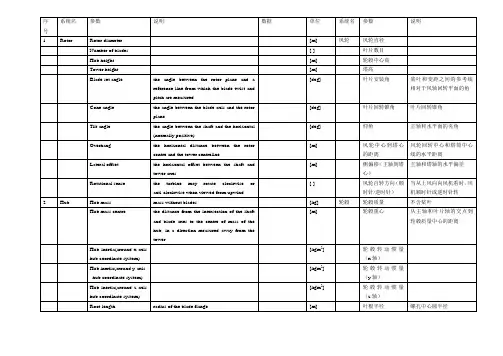
Instruction ManualProduct Type: SFG21F-C5A Primary Fan Product Code: T515Document No.: T515SYDelivery No.:Delivery Date:SHENYANG BLOWER VENTILATING CO.,LTDContents1.Fan Application2.Main Technical Parameter of Fan3.Performance Parameter4.Fan Performance Conversion5.Fan StructureRotor setJournal Bearing、Thrust BearingCasingInlet BoxSuctionDamperSuction、Discharge Companion Flanges6.Fan Installation7.Running of FanRunning-test of FanEmergent shut down and Steps8.Fan MaintenanceCaution of MaintenanceCaution of OperationFan Troubles and reasons9.Fan Overhaul9.1 Fan Disassembly Steps9.2 Main Overhaul Items10.Attached Drawing of Instruction1. Fan ApplicationSFG21F-C5A primary fan is Indonesia Pelabuhan ratu 3x350MW coal fired power plant, Inlet medium temperature is 37.8℃.2.Main Technical Parameter of Fan:2.1 Fan type: Centrifugal type with single suction and double-support2.2 Air inlet direction: 90°(right-hand rotating)2.3 Air outlet direction: 30°(right-hand rotating)2.4 Impeller diameter: 2050mm (at blade tip)2.5 Max. Circumference speed of impeller: 159m/s2.6 Rotor flywheel moment GD2: 4800kg-m22.7 Rotor set weight: 2343kg2.8 Total fan weight: 12000kg3.Performance parameter3.1 Design parameters:Total pressure Pa: 14800Inlet flow m3/S: 98.36Inlet temperature ℃: 37.8Medium density kg/m3: 1.119Fan total pressure inner efficiency %:85Fan rotating speed r/m: 1493Shaft power Kw: 1790Motor power Kw: 20003.2 Fan performance curve (see Page 14)4. Fan performance conversionIf medium density changes, fan performance converts as the following formula:Q1=Q2; P1/P2=ρj1/ρj2; N1/N2=ρj1/ρj2;Q1/Q2=n1/n2; P1/P2=(n1/n2)2; N1/N2=(n1/n2)3Air density changes with inlet temperature and atmosphere pressure, their relation is:ρ1/ρ2 = (Pj1/Pj2)×{(273+tj2)/(273+tji)}Q-Flow; P-Pressure; N-power; ρ-density; j-inlet5.Fan Structure:Fan is mainly consisting of rotor set、support bearing、thrust bearing、casing、air inlet box、air inlet suction、damper、suction and discharge companion flanges etc.5.1 Rotor SetRotor set、coupling、support bearing、thrust bearing、base-plate composea rotation system. Rotor set is made up of impellers and shafts, impeller ismade up of blade、wheel cover、main disc and hub. Ten backward airfoil blades are welded between curved wheel cover and plate main disc. Blade、wheel cover、main disc materials are all 15Mnv, impeller welding seam have passed dye penetrate test and been regulated by static and dynamic balance, so the operation shall be safe and stable. The advantages of the impeller is high efficiency、low noise、high intensity. Material of main shaft is No.45 steel.5.2 Journal bearing and thrust bearingRolling bearing has been adopted to journal bearing and thrust bearing.Bearing adopts oil lubrication and water-cooling for bearing box. Lube oil is GB11120-89 steam turbine oil, and brand No. N46. Bearing box uses lapping type oil throwing ring, aluminum bisect oil seal and asbestos packing. Oil level indicator is set on bearing box. For height of oil level, please see fan general diagram. Bearing cooling water sleeve is together within bearing box, when bearing temperature is high, it may cool by water, cooling water pressure is 0.2-0.3Mpa and flow is 2-3 t/h. Double-branch platinum thermal resistance used for measuring temperature of bearing and bi-metal thermometer have been installed on bearing box.5.3 CasingCasing is welded with steel plate Q235A, it is of split structure, equipped with a manhole door and drain, which is easier for maintenance.5.4 Inlet boxInlet box is welded with steel plate Q235A, and split structure, which is easier for maintenance. One side of which is connected with suction, and the other side is connected with damper. In order to increase stiffness of inlet box, supporting pipes have been welded in it.5.5 SuctionSuction is welded with steel plate Q235A, and split structure, which is easier for maintenance. One side of which is connected with casing, and the other side is connected with inlet box. In order to increase its stiffness, rib plates are welded along the circumference between two flanges.5.6 DamperThere are 6 blades in damper, it can get better regulating efficiency by regulating air inlet capacity through changing the opening of guide vane and changing the characteristics of fan. The requirement of running conditions may be satisfied by regulating electric actuator and the angle ofguide vane through transmission shaft.5.7 Companion flangesCompanion flanges are provided for easy installation, and the user may weld his connecting pipes onto the suction and discharge flanges separately.6. Fan InstallationBefore installation, foundation should be prepared according to the basic dimension sketch of fan and electric motor and keep enough space for secondary grouting. At the same time, required materials, tools and equipments should be prepared (Lifting weight of biggest fan parts is 2343 kg), on the other hand, the packed parts of fan should be checked, the parts in case of damage, should be repaired and replaced immediately.Impeller and main shaft should be checked more carefully, inner of bearing box should be cleaned with kerosene. Cooling water pipe should be cleaned up without any obstruction.In order to prevent rust and reduce disassembly difficulty, lubricating grease or machine oil should be coated on the connecting surface. The connection bolts should be tightened after position pin is in place.Tighten the anchor bolts temporarily for the installation of casing with anchor bolts, check casing and pipes inner carefully, and make sure that noforeign matters, such as tools are left inside.Installation Steps:(1)Place anchor bolts first, and then put lower casing in position.(2) Put the bearing baseplate and lower bearing in position, axial and horizontal leveling should be made with reference to the hole of bearing and deviation of which should be no more than 0. 10 mm/ m.(3)Put the assembled rotating parts (including impeller, main shaft, bearing,oil whip ring etc.) into the bearing baseplate.(4)Assemble the upper cover of bearing box, measure clearance between oilseal and oil whip disc according to the dimensions provided on the drawings of journal bearing and thrust bearing, and ensure that radial clearance of main shaft and oil seal is uniformly filled with asbestos packing, tighten side covers and oil seals on two ends, connect cooling water pipe and then fill bearing box with new lube oil.(5)When installing suction, axial and radial clearance between suction andimpeller should be adjusted according to required dimension on general drawing of fan in order to guarantee high efficiency of fan.(6)Put the upper casing in position and tighten bolts between suction andcasing.(7)Connect inlet box with suction.(8)Pay attention to direction of the damper during assembly。
上海通用风机股份有限公司通用风机安装维护使用说明书目录Content页次page 一、安装概述Summarize of installation (2)⒈风机安装场所P o s i t i o n (2)⒉风机安装空间要求D e m a n d s o f space (2)⒊各种安装方法及要求Methods and demands of installation (3)⒋吊装于天棚的场合Situation of loaded on the ceiling (5)二、基础B a s i c (5)⒈混凝土基础C o n c r e t e b e d r o c k (5)⒉减振元件S h a k e p r o o f e l e m e n t (6)⒊减振元件的使用Using of the shakeproof element (7)三、搬运T r a n s i t (7)⒈部件检查C h e c k t h e p a r t s (8)⒉吊装及搬运Hoi st and t ransi t (8)⒊保管S a f e k e e p i n g (8)四、安装方法M e t h o d s o f i n s t a l l a t i o n (9)⒈水平校正P l a n e e m e n d a t i o n (9)⒉轴承座的安装Installation of bearing house (10)⒊确认电机转向Notarized the motor direction (13)⒋带轮及胶带P u l l ey and V-bel t (13)⒌联轴器校正S haft joint emendation (13)⒍管道连接J o i n o f p i p e (14)⒎热风机的安装Installation of hot-air blower (14)五、试车C o m m i s s i o n i n g (15)⒈检查C h e c k i n g (15)⒉加油P u t o n s t e a m (15)⒊盘车J i g g e r (15)⒋送风系统A i r-f e e d i n g s ys t e m (16)⒌电气配件E l ect ri c fi t t i ngs (16)⒍启动S t a r t u p (16)⒎运行确认N o t a r i z e t h e r u n n i n g (17)六、保养与管理M a i n t e n a n c ea n d m a n a g e m e n t (18)⒈定期检查P e r i o d i c c h e c k (18)⒉日常检查D a i l y c h e c k (22)⒊轴承的保养和检查Maintenance and checking of bearing (23)⒋联轴器的保养和检查Maintenance and checking of shaft joint (26)⒌胶带及带轮的保养和检查Maintenance and checking of pulley and V-belt (26)七、安全须知S afet y caut i on (29)非常感谢您选用创新精良的“上树”牌风机!First, thanks for selecting our innovative and excellent fans with “上树” brand!正确的安装和维护关系到风机性能及使用寿命。
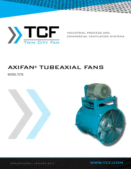
CATALOG AX200 | JANUARY 2013WWW.TCF.COMMODEL TCTATCVA AXIFAN® Vaneaxial Fan, except that guide vanes are notprovided. This makes the TCTA more suitable for lower pres-sures and provides cost savings.Capabilities• Wheel diameters 12" to 60"• Airflow to 96,000 CFM• Static pressures to 5" w.g.• 37 unique diameters and hub-to-tip ratiosAXIFAN® WheelThe heart of the TCTA AXIFAN® fan lies in its wheel. Cast ofhigh strength aluminum alloy, the one-piece TCTA AXIFAN®wheel has been developed to maximize the highest efficiencypossible. Attention to detail in blade and hub design have cre-ated what is felt to be the most efficient and reliable axial fanon the market today. With the wide range of hub-to-tip ratiosavailable, there is a TCTA AXIFAN® to meet any air movementrequirement.Hub-To-Tip RatioThe multitude of TCTA AXIFAN®wheels evolves from ninebasic castings. Each casting is machined and cut to the properdiameter. By cutting the same model casting to one of severaldifferent diameters, different hub-to-tip ratios are created. Sinceeach hub ratio has slightly different pressure/efficiency charac-teristics, the freedom of having several wheels (different hubratios) for a set diameter provides the opportunity to maximizeefficiency at the required point of rating.HousingTCTA AXIFAN® housings are one-piece, heavy-gauge, hot-rolledsteel construction. Flanges on both the inlet and outlet are inte-grally rolled and punched for attachment to ductwork or acces-sories as necessary. The seam is continuously welded andground smooth to assure efficient airflow through the housing.Drive Isolated from AirstreamThe shaft and bearing assembly is mounted within the innercylinder to isolate these components from the high velocityairstream.The V-belt drive assembly is extended through a two-piece beltfairing. The belt fairing is an aerodynamically designed tube,designed to maximize fan efficiency, minimize air blockage andreduce noise generation.Additional InformationFor additional information on the TCTA and TCVA AXIFAN®tubeaxial and vaneaxial fans, refer to Twin City Fan & BlowerCatalog AX100.This catalog contains performance tables for Arrangement 9belt driven fans. For Arrangement 4 direct drive selections andadditional selections not shown, refer to the Twin City Fan &Blower Fan Selector Program.36 B 5Approximation of Hub-To-Tip RatioWhere:3 = 40%, 4 = 43%, 5 = 50%6 = 57%,7 = 66%DriveB = Belt Driven (Arr. 9)D = Direct Drive (Arr. 4)Fan Diameter (inches)~~~~~Model TCTA is available with UL/C UL 705 listing for electrical, File No.E158680.TCTA Arr. 9AXIFAN® WheelModel NomenclatureTUBEAXIAL F ANSTWIN CITY FAN - CATALOG AX2002PERFORMANCE DATAWheel Dia.: 12"Outlet Area: 0.807 ft2Tip Speed: 3.14 x RPMWheel Dia.: 15"Outlet Area: 1.253 ft2Tip Speed: 3.93 x RPMRegular type face = Class I Bold type face = Class II Maximum RPM: Class I = 3540 Class II = 4552TWIN CITY FAN - CATALOG AX2004Wheel Dia.: 18"Outlet Area: 1.799 ft 2 Tip Speed: 4.71 x RPMWheel Dia.: 21"Outlet Area: 2.448 ft 2Tip Speed: 5.50 x RPMRegular type face = Class I Bold type face = Class IIMaximum RPM: Class I = 2971 Class II = 4000 (Sizes 18B4 and 18B5)Class II = 3820 (Sizes 18B6 and 18B7)Regular type face = Class I Bold type face = Class IIMaximum RPM: Class I = 2546 Class II = 4000 (Size 21B4) Class II = 3709 (Size 21B5)Class II = 3738 (Size 21B6) Class II = 3274 (Size 21B7)PERFORMANCE DATAPERFORMANCE DATAWheel Dia.: 24"Outlet Area: 3.191 ft2Tip Speed: 6.28 x RPMClass II = 2971 (Size 24B6) Class II = 2865 (Size 24B7)Wheel Dia.: 28"Outlet Area: 4.353 ft2Tip Speed: 7.33 x RPMRegular type face = Class I Bold type face = Class II Maximum RPM: Class I = 1910 Class II = 2456TWIN CITY FAN - CATALOG AX2006Wheel Dia.: 32"Outlet Area: 5.672 ft 2Tip Speed: 8.38 x RPMWheel Dia.: 36"Outlet Area: 7.166 ft 2Tip Speed: 9.42 x RPMRegular type face = Class I Bold type face = Class IIMaximum RPM: Class I = 1671 Class II = 2396 (Size 32B4) Class II = 2234 (Size 32B5)Class II = 2149 (Sizes 32B6 and 32B7)Regular type face = Class I Bold type face = Class II Maximum RPM: Class I = 1485 Class II = 2314 (Size 36B4) Class II = 2176 (Size 36B5)Class II = 2052 (Size 36B6) Class II = 1987 (Size 36B7)PERFORMANCE DATAPERFORMANCE DATAWheel Dia.: 42"Outlet Area: 9.793 ft2Tip Speed: 11.00 x RPMRegular type face = Class I Bold type face = Class II Maximum RPM: Class I = 1273 Class II = 1805 (Size 42B4)Class II = 1684 (Size 42B5) Class II = 1637 (Size 42B6)Wheel Dia.: 48"Outlet Area: 12.77 ft2Tip Speed: 12.57 x RPMRegular type face = Class I Bold type face = Class II Maximum RPM: Class I = 1114 Class II = 1654 (Size 48B4)Class II = 1542 (Size 48B5)TWIN CITY FAN - CATALOG AX2008Wheel Dia.: 54"Outlet Area: 16.12 ft 2Tip Speed: 14.14 x RPMRegular type face = Class I Bold type face = Class IIMaximum RPM: Class I = 990 Class II = 1444 (Size 54B3)Class II = 1348 (Size 54B4)Wheel Dia.: 60"Outlet Area: 19.87 ft 2Tip Speed: 15.71 x RPMRegular type face = Class I Bold type face = Class II Maximum RPM: Class I = 891 Class II =1146PERFORMANCE DATAMOTORARR. 4 – VERTICAL ARR. 9 – VERTICALARR. 4 – HORIZONTAL ARR. 9 – HORIZONTALAIRFLOW AIRFLOWAIRFLOW AIRFLOWVDO/VDN VDIVUI/VUN VUOCDBAEGFHHORIZONTALMOTORLOCATIONS(VIEWED FROMFAN OUTLET)VDO= Vertical Down Floor Mounted With LegsVDN = Vertical Down Discharge Without LegsVDI= Vertical Down Ceiling Hung With LegsVUI= Vertical Up Floor Mounted With LegsVUN = Vertical Up Discharge Without LegsVUO= Vertical Up Ceiling Hung With LegsHORIZONTAL DISCHARGESHOR = Horizontal – No Clips or Legs HCH = Horizontal Ceiling Hung with Suspension Clips HBM = Horizontal Base Mounted with Support LegsVERTICAL DISCHARGESDIMENSIONS ARE NOT TO BE USED FOR CONSTRUCTION. CERTIFIED DRAWINGS AVAILABLE UPON REQUEST.AC13597B AC13793ADIMENSIONAL DATA10AIRFLOWCONE COMPANION VARIABLE INLET BELLFLANGE INLET VANEDIMENSIONS ARE NOT TO BE USED FOR CONSTRUCTION. CERTIFIED DRAWINGS AVAILABLE UPON REQUEST.AC13716M DIMENSIONAL DATATwin City FanTYPICAL SPECIFICATIONSFans shall be Model TCTA AXIFAN® Tubeaxial Fans as manufactured by Twin City Fan & Blower, Minneapolis, Minne-sota. Fans shall be Arrangement 9, V-belt driven with the wheel mounted on a separate shaft and bearings supported completely within an enclosed tube isolated from the high velocity airstream or Arrangement 4, with the propeller mounted directly on the motor shaft and with the propeller and motor assembly enclosed entirely within the fan casing. PERFORMANCE — Fans shall be tested in accordance with ANSI/AMCA Standard 210 (air performance) and 300 (sound performance) in an AMCA accredited laboratory.Model TCTA shall be available UL 705 listed. Fans shall bear a permanently attached nameplate displaying model and serial number of the unit for future identification.HOUSING — Fan housings shall be welded of 14-gauge ASTM A-569 hot rolled steel on size 12, 12-gauge hot rolled steel on sizes 15 through 21, 10-gauge hot rolled steel on sizes 24 through 36, and 7-gauge hot rolled steel on sizes42 through 60. Inlet and outlet flanges are standard.WHEEL — The fan wheel shall be a solid one-piece sand casting of 319 alloy aluminum and shall contain seven blades and an integral center hub. The wheel shall have blades of airfoil shape designed with a variable hub ratio system to allow the selected fan to operate at the highest efficiency possible. Wheels shall be machined to the proper diameterso that blade tip clearance shall be within tolerance necessary to insure certified fan performance. The wheel shall be secured to the fan/motor shaft with a Trantorque® or taperlock bushing.SHAFT (ARR. 9) — Shafts shall be AISI 1040 or 1045 hot rolled steel, accurately turned, ground, polished, and ring gauged for accuracy. Shafts shall be sized for the first critical speed of at least 1.43 times the maximum speed. BEARINGS (ARR. 9) — Bearings shall be heavy duty, grease lubricated, anti-friction ball or roller, self-aligning, pillow block type and selected for a minimum average bearing life (AFBMA L-50) in excess of 200,000 hours at the maximum fan RPM. All bearings are provided with pre-filled factory extended lubrication lines terminating at the housing exterior. DRIVE (ARR. 9) — The fan shall be equipped with a (fixed/adjustable) pitch V-belt drive selected to operate the fan at the correct operational RPM. The V-belt drive shall consist of cast iron sheaves and anti-static conducting belts and shallbe selected with a (1.2/1.5) safety factor based upon the required brake horsepower of the fan.The complete fan shaft and bearing assembly is mounted within a steel fabricated inner cylinder. The V-belt drive as-sembly is extended through a two-piece belt fairing. The belt fairing shall be an aerodynamically shaped tube designedto maximize fan efficiency. The belt fairing is welded continuously to both the inner cylinder that houses the fan shaft and bearings and the fan housing.MOTOR — Motors for Arrangement 9 fans shall be manufactured in accordance with current applicable standards. Mo-tors shall be foot-mounted, NEMA standard (ODP, TEFC, Explosion-Proof), continuous duty, ball bearing type with class (B, F) insulation and of cast iron construction when commercially available.Motors for Arrangement 4 fans shall be foot-mounted, NEMA standard, totally enclosed fan cooled (TEFC), continuous duty, ball bearing type with class “F” insulation and of cast iron construction when commercially available. For easein wiring the motor, wiring connections shall be extended to an exterior conduit box located on the exterior of the fan housing. A duplicate motor nameplate shall be mounted on the exterior of the fan adjacent to the fan nameplate. External grease fittings with pre-filled factory extended grease leads shall be supplied for lubrication of the motor bearings on all motors that provide grease fittings.FINISH — The entire fan assembly, excluding the shaft, shall be thoroughly degreased and deburred before application ofa rust-preventative primer. After the fan is completely assembled, a finish coat of paint shall be applied to the entire as-sembly. The fan shaft shall be coated with a petroleum-based rust protectant. Aluminum components shall be unpainted. FACTORY RUN TEST — All fans with motors and drives mounted by Twin City Fan & Blower shall be completely as-sembled and test run as a unit at the specified operating speed prior to shipment. Each wheel shall be statically and dynamically balanced in accordance with ANSI/AMCA 204-96 “Balance Quality and Vibration Levels for Fans” to Fan Application Category BV-3, Balance Quality Grade G6.3. Balance readings shall be taken by electronic type equipmentin the axial, vertical, and horizontal directions on each of the bearings. Records shall be maintained and a written copy shall be available upon request.GUARANTEE — The manufacturer shall guarantee the workmanship and materials for its TCTA AXIFAN® tubeaxial fansat least one (1) year from startup or eighteen (18) months from shipment, whichever occurs first.TWIN CITY FAN & BLOWER WWW.TCF .COM5959 TRENTON LANE N | MINNEAPOLIS, MN 55442 | PHONE: 763-551-7600 | FAX: 763-551-7601CENTRIFUGAL FANS | UTILITY SETS | PLENUM & PLUG FANS | INLINE CENTRIFUGAL FANSMIXED FLOW FANS | TUBEAXIAL & VANEAXIAL FANS | PROPELLER WALL FANS | PROPELLER ROOF VENTILA TORS CENTRIFUGAL ROOF & WALL EXHAUSTERS | CEILING VENTILA TORS | GRAVITY VENTILA TORS | DUCT BLOWERS RADIAL BLADED FANS | RADIAL TIP FANS | HIGH EFFICIENCY INDUSTRIAL FANS | PRESSURE BLOWERS LABORA TORY EXHAUST FANS | FILTERED SUPPL Y FANS | MANCOOLERS | FIBERGLASS FANS | CUSTOM FANSINDUSTRIAL PROCESS ANDCOMMERCIAL VENTILATION SYSTEMS ©2018 Twin City Fan Companies, Ltd., Minneapolis, MN. All rights reserved. Catalog illustrations cover the general appearance of Twin City Fan & Blower products at the time of publication and we reserve the right to make changes in design and construction at any time without notice.Twin City FanTwin City Fan。
4-72-8C离心式通风机使用说明书4-72-8C Centrifugal FanInstruction河南固德重型机器制造有限公司HENAN GUDE HEA VY MACHINERY MANUFACTURING COMPANG LTD地址:郑州市郑上路196号Add:No.196 Zhengshang Road,Zhengzhou,China电话(Tel):0086-371-68185666传真(Fax):0086-371-68183666邮箱(Email):*****************一.用途4-72-8c型离心通风机主要用途是为—般工厂及大型建筑物的室内通风换气或输送空气及其它不自燃、不易爆、不挥发、对人体无害、对钢材无腐蚀性之气体。
4-72-8c离心通风机输送的气体均不得含粘性物质,所含尘土及硬质颗粒物不大于150mg/m3,气体温度不得超80℃。
ageThe main use of 4-72-8c type centrifugal fan is for indoor ventilation as factories and large buildings or the air transport and other spontaneous which is not explosive, volatile, on harmful to the human body, no corrosion to steel.The delivery gas by 4-72-8c centrifugal fan shall not contain viscous substances, dust and hard particles containing is no more than 150mg / m3, the temperature of the gas shall not exceed80 ℃二.型式从电机—端正视,凡叶轮按顺时针方向旋转者均称“右旋风机”,以“右”表示,反之则均称之为“左旋风机”以“左”表示。

目录1、序言 (1)2、运行参数 (1)3、功能简介 (1)4、运行 (2)5、维护 (4)6、组装 (5)7、润滑 (12)8、备件 (13)9 、防护 (14)10、故障分析 (15)11、安装数据 (17)12、附图 (18)特别说明 (22)1、序言1.1 用户须知本说明书供安装、运行、维护人员认真阅读,严格遵循,风机的安装和维护工作必须由专业人员承担。
本说明书内容若有重要的变更,CPMW将寄给用户附有修订的页面,个别更改不另通知。
大型风机、高温风机和双级风机等,与常规风机部分结构和安装方式略有差异,应参照随机技术资料,注意区分。
1.2 安全条例本机只适用合同文件中明确指定的用途,不含其它或更广泛的用途。
本机安装、操作、维护只限下列人员:指定的安全负责人、接受过必要的培训且有必要经验的人员。
风机的安装和检查工作遵照下列规定:——主电机必须关闭并避免被无意间打开(电绝缘);——执行装置和辅助设备如油泵、冷却密封风机必须关闭并避免意外开启;——不允许有害气体直接进入或通过管路进入风机内部,入口温度必须安全;——本说明书对可能给人身、设备或环境造成伤害的情况进行提示,须严格遵循。
2、运行参数(请见协议签订后提供的前期配合设计资料中相关性能曲线及选型表格)2.1 运行条件2.2 运行参数限制:CPMW不承担非正常使用和超出规定范围使用风机造成损坏的责任。
——风机及配件按用户提供参数进行选型设计,若参数改变,应告之CPMW确认其可行性;——电机转速:电源频率波动导致的转速波动不能超过运行数据规定的2%;——气体温度:风机入口气体温度最大不能长时间超过150℃,或200℃时最长不得超过5分钟,若超过限制,须检查风机损害并与CPMW联系;——风机应尽量避免在不稳定区域运行,否则易导致失速喘振及系统设备故障和损坏,该区域在特性曲线图上可以查到;——风机不得在冰冻、卡涩、逆转、腐蚀、爆炸和含尘气体浓度超标等状况下启动和运行。
496 04 5302 00 August 2010TECHNICAL SUPPORT MANUALFan CoilsFEM4X, WAHM, WAHTTABLE OF CONTENTSModel Number Identification 2 − 3..................Wiring Diagram 4................................Airflow Charts 5 − 6...............................Exploded Views 7 − 13............................Parts List FEM4X 14.............................Parts List WAHM 15 − 17..........................Parts List WAHT 18 − 20..........................MODELSFEM4X6000B1FEM4X6000BT1WAHM184A2 WAHT184A2WAHM244A2 WAHT244A2WAHM304A2 WAHT304A2WAHM364A2 WAHT364A2WAHM424A2 WAHT424A2WAHM484A2 WAHT484A2WAHM604A2 WAHT604A2TECHNICAL SUPPORT MANUAL Fan Coils: FEM4X, WAHM**(4), WAHT**(4)2496 04 5301 01FAN COIL MODEL NUMBER IDENTIFICATION GUIDEF E M 4X 1800A 1F = Fan CoilS = Standard PSCE = High Efficiency ECM MOTOR TYPE U = UpflowM = MultipositionINSTALLATION TYPE4 = Environmentally Sound R −410A REFRIGERANTX = TXVMETERING DEVICE1800 = 18,000 BTUH = 1−1/2 tons 2400 = 24,000 BTUH = 2 tons 3000 = 30,000 BTUH = 2−1/2 tons 3500 & 3600 = 36,000 BTUH = 3 tons 4200 = 42,000 BTUH = 3−1/2 tons 4800 = 48,000 BTUH = 4 tons 6000 = 60,000 BTUH = 5 tons NOMINAL CAPACITYSales CodeEngineering RevisionFAN COIL MODEL NUMBER IDENTIFICATION GUIDEDigit Position:1, 2345, 6789Example Part Number:WAHM244A 1WA = Air Handler S = Standard MotorH = High Efficiency MotorMOTOR TYPEM = Multiposition Plain Copper Evaporator CoilT = Multiposition Tin −coated Copper Evaporator Coil INSTALLA TION TYPE 18 = 18,000 BTU/hr = 1−1/2 TONS 24 = 24,000 BTU/hr = 2 TONS 30 = 30,000 BTU/hr = 2−1/2 TONS 36 = 36,000 BTU/hr = 3 TONS 42 = 42,000 BTU/hr = 3−1/2 TONS 48 = 48,000 BTU/hr = 4 TONS 60 = 60,000 BTU/hr = 5 TONS NOMINAL COOLING CAPACITY 4 = R −410A REFRIGERANTSALES DIGIT EXTRA DIGITTECHNICAL SUPPORT MANUAL Fan Coils: FEM4X, WAHM**(4), WAHT**(4)496 04 5301 013ACCESSORIES PART NUMBER IDENTIFICATION GUIDEEB AC 01NCBAEB = Evaporator Blower AC = Accessory01 = Product Identifier Number NCB = Non −Combustible Base Kit DFK = Down Flow KitPLG = Power Plug (no heat kit)SPK = Single Point Wiring Kit FKS = Filter Kit Small FKM = Filter Kit Medium FKL = Filter Kit LargeFKX = Filter Kit Extra LargeCTK = Condensate Trap Kit (PVC pipe)Sales CodeELECTRIC HEATER MODEL NUMBER IDENTIFICATION GUIDEEHK 05A K N1EHK = Electric Heater Kit05 = 5 kW 07 = 7 kW 09 = 9 kW 10 = 10 kW 15 = 15 kW 18 = 18 kW 20 = 20 kW 25 = 25 kW 30 = 30 kW NOMINAL HEAT VALUE Sales CodeK = 208 / 230 single −phase H = 208 / 230, 3−phaseKC = 208 / 230, supplied as single phase, field convertible to 3−phase HC = 208 / 230 supplied as 3−phase, field convertible to single phase VOLTAGE (60 Hz)Product Identifier Engineering CodeTECHNICAL SUPPORT MANUAL Fan Coils: FEM4X, WAHM**(4), WAHT**(4)4496 04 5301 01TECHNICAL SUPPORT MANUAL Fan Coils: FEM4X, WAHM**(4), WAHT**(4)496 04 5301 015AIRFLOW PERFORMANCE − CFM at a given Speed and Static readingModelWAHM, WAHTBlower Speed Measured Static Pressure, inlet to outlet (inches water column)0.100.200.300.400.500.60WAHM4A18*WAHT184A*High 766739706666619566Medium 701659619578538499Low 614572530486441396WAHM244A*WAHT244A*High 941905868830792753Medium 823786747707665622Low 633583533482431378WAHM304A*WAHT304A*High 1130109710631028992955Medium 10331000965928888846Low 840802760713663609WAHM364A*WAHT364A*High 143713981354130812571204Medium 128212381192114210901036Low 1168111810671014959903WAHM424A*WAHT424A*High 161615781533148014201353Medium 147914371392134412931240Low 130312581211116111081054WAHM484A*WAHT484A*High 180517721739170416691632Medium 165216171581154315041463Low 145814181377133512921248WAHM604A*WAHT604A*High 205720241989195419161878Medium 179917661731169516581618Low166716331596155815171475NOTES:1.Airflow based on dry coil at 230V with factory approved filter and electric heater(2 element heater for model sizes 1800 − 3600, 3 element heater for model sizes 4200 − 6000)2.Not recommended for use above 0.60 inches water column external static pressure.3.Shaded cells indicate airflow is greater than 450 CFM per ton.AIRFLOW PERFORMANCE − CFM at a given Speed and Static readingModelBlower SpeedMeasured Static Pressure, inlet to outlet (inches water column)0.100.200.300.400.500.60FEM4X6000BTap 5189718671836180817741736Tap 4181717851757172416931655Tap 3181717851757172416931655Tap 2165716211589155715181474Tap 1144314121377133212861243TECHNICAL SUPPORT MANUAL Fan Coils: FEM4X, WAHM**(4), WAHT**(4)6496 04 5301 01STATIC PRESSURE CORRECTION FROM DRY TO WET COIL (inches of water column)Airflow performance chart above was developed using fan coils with DRY coils.When taking a static reading across a WET coil, adjust the static pressure numbers above by adding the values in this table (for a given CFM, wet coil will have greater static pressure drop than dry coil).Model WAHM, WAHT CFM 50060070080090010001100120013001400150016001700180019002000WAHM184A*WAHT184A*.034.049.063−−−−−−−−−−−−−WAHM244A*WAHT244A*.016.027.038.049.059−−−−−−−−−−−WAHM304A*WAHT304A*−−−.049.059.070.080−−−−−−−−−WAHM364A*WAHT364A*−−−−−.055.064.073.081−−−−−−−WAHM424A*WAHT424A*−−−−−−−.049.056.063.070−−−−−WAHM484A*WAHT484A*−−−−−−−−−.038.043.049.054.059−−WAHM604A*WAHT604A*−−−−−−−−−−−.027.031.035.039.043STATIC PRESSURE CORRECTION FROM DRY TO WET COIL (inches of water column)Airflow performance chart on page 7 was developed using fan coils with DRY coils.When taking a static reading across a WET coil, adjust the static pressure numbers on pages 7−8 by adding the values in this table (for a given CFM, wet coil will have greater static pressure drop than dry coil).Model Size CFM 50060070080090010001100120013001400150016001700180019002000FEM4X6000B−−−−−−−−−−−.049.054.059.065.070STATIC PRESSURE DROP ACROSS FILTER (inches of water column)Model WAHM, WAHT CFM 400600800100012001400160018002000WAHM184A*WAHT184A*.020.044.075−−−−−−WAHM244A*WAHT244A*−.044.075.110−−−−−WAHM304A*WAHT304A*−−.048.072.100−−−−WAHM364A*WAHT364A*−−−.072.100.130−−−WAHM424A*WAHT424A*−−−−.070.092.120−−WAHM484A*WAHT484A*−−−−−.092.120.152−WAHM604A*WAHT604A*−−−−−−.120.152.187STATIC PRESSURE DROP ACROSS FILTER (inches of water column)Model Size CFM 400600800100012001400160018002000FEM4X6000B−−−−−−.086.105.130TECHNICAL SUPPORT MANUAL Fan Coils: FEM4X, WAHM**(4), WAHT**(4)496 04 5301 017TECHNICAL SUPPORT MANUAL Fan Coils: FEM4X, WAHM**(4), WAHT**(4)8496 04 5301 01TECHNICAL SUPPORT MANUAL Fan Coils: FEM4X, WAHM**(4), WAHT**(4)496 04 5301 019TECHNICAL SUPPORT MANUAL Fan Coils: FEM4X, WAHM**(4), WAHT**(4)10496 04 5301 01496 04 5301 011112496 04 5301 01496 04 5301 011314496 04 5301 01FEM4X Parts ListKEY NO.DESCRIPTIONPART NO.F E M 4X 6000B 1F E M 4X 6000B T 101BLOWER ASSY DD11-911796581102TRANSFORMER11720281104HARNESS ASSY BLOWER 11716761105FILTER HH 21.5X19.875X11171653−106TXV11833111107COIL AND HEADER ASY 11833131−07COIL & HDR ASSY1183368−108STRAINER11717401109CONDENSATE PAN11796741110CONDENSATE PAN ASY 11796761111WHEEL BLOWER11717421112MTR BLR 1/230 3/4 HP11796861113HARNESS ASY ECMX FAN COIL 1178976−114PANEL CUTOFF BLWR 11715721115LUG GROUND11706771116DISTRIBUTOR ASY117160611A PANEL ASSY TOP INSUL 117236211AA PLATE HEATER117158111B DOOR ASSY LOWER INSUL 117379511BB DECK BLOWER117158811C DOOR ASSY UPPER INSUL 117379611D DOOR ASSY FITTING INSUL 117970311E DOOR ASSY FILTER117193511F BARRIER LOW VOLTAGE 117166011G BAFFLE DIFFUSER 117156922H SPRING117255411J TUBE DRAIN117233711K GROMMET SUCTION 117162211L PLUG BUTTON 117376411LL FITTING DRAIN 117163611M SUPPORT PAN 117263611MM FITTING DRAIN 117163511N BRACKET COIL 117157422P BRACKET COIL 117157522PP CAP117494911Q SHIELD COND PAN 117232822R AIR SEAL ASSY 117164111RR CAP117495011S TROUGH CNDS 117163811T TROUGH CNDS 117163711U BAFFLE DRIP 117164712V RING DRIP117164911W BAND MTR MOUNT117156611X HOUSING BLOWER FAN11770691−XHOUSING BLR REPLACEMENT KIT1183119−1Y ARM AND GROMMET ASSY 117379114Z SCREW SPECIAL 117063644Parts Not Shown)(HARNESS ASSY UNIT11789761−)(HEX HD 10AB 1/2117707131−)(HEX HD 10AB 5/8117707212−)(GROMMET LIQUID 117162011)(PLATE FILLER 11716951−)(FUSE 3A1179701−1)(GROMMET117173711)(PAINT DARK GREY 16OZ AEROSOL117135711496 04 5301 0115WAHM Parts ListKEY NO.DESCRIPTIONPART NO.W A H M 184A 2W A H M 244A 2W A H M 304A 2W A H M 364A 2W A H M 424A 2W A H M 484A 2W A H M 604A 201BLOWER ASSY 11789691------01BLOWER ASSY 1178970-1-----01BLOWER ASSY 1178971--1----01BLOWER ASSY 1178972---1---01BLOWER ASSY 1178973----1--01BLOWER ASSY 1178974-----1-01BLOWER ASSY 1178975------102TRANSFORMER1172028111111104HARNESS ASSY BLOWER 1171676111111105FILTER LO EFF 11720701------05FILTER LO EFF 117165211----05FILTER LO EFF 1171653--111-05FILTER LO EFF 1171654106TXV 117234811-----06TXV 1178991106TXV 1172349--1---06TXV 1178990106TXV1172350----1107COIL AND HEADER ASY 11737651------07COIL AND HEADER ASY 11789841-----07COIL AND HEADER ASY 1173766-1----07COIL AND HEADER ASY 1172887--1---07COIL AND HEADER ASY 1173768---1--07COIL AND HEADER ASY 1172333----1-07COIL AND HEADER ASY 1178985108STRAINER1171740111111109CONDENSATE PAN 1171673----1--09CONDENSATE PAN 1171674----1-09CONDENSATE PAN1171675-----110CONDENSATE PAN ASY 11752061------10CONDENSATE PAN ASY 11752071110CONDENSATE PAN ASY 1178986110CONDENSATE PAN ASY 11789871110CONDENSATE PAN ASY 1178988111WHEEL BLOWER 1171743111WHEEL BLOWER 1171744111WHEEL BLOWER 1171745111WHEEL BLOWER 11717411111WHEEL BLOWER 11717421112MOTOR BLOWER 1178977112MOTOR BLOWER 1178978-1-----12MOTOR BLOWER 1178979-1----12MOTOR BLOWER 1178980--1---12MOTOR BLOWER 1178981---1--12MOTOR BLOWER 1178982----1-12MOTOR BLOWER1178983-----113HARNESS ASSY BLOWER ECMX 1175754111111114CUTOFF 1171570114CUTOFF 1171571114CUTOFF1171567116496 04 5301 01WAHM Parts ListKEY NO.W A H M 604A 2W A H M 484A 2W A H M 424A 2W A H M 364A 2W A H M 304A 2W A H M 244A 2W A H M 184A 2PART NO.DESCRIPTION14CUTOFF 11715681114CUTOFF11715721115LUG GROUND1170677111111116DISTRIBUTOR ASY 1172624116DISTRIBUTOR ASY 11716031116DISTRIBUTOR ASY 1172888116DISTRIBUTOR ASY 1172983116DISTRIBUTOR ASY 1171606116DISTRIBUTOR ASY11716051A PANEL ASSY TOP INSUL 11771441A PANEL ASSY TOP INSUL 11770501-----A PANEL ASSY TOP INSUL 1177047-1----A PANEL ASSY TOP INSUL 1177048--1-1-A PANEL ASSY TOP INSUL 1177051---1--A PANEL ASSY TOP INSUL 1177049-----1AA PLATE HEATER 11715831AA PLATE HEATER 117158411----AA PLATE HEATER 1171581--111-AA PLATE HEATER1171582-----1B DOOR ASSY LOWER INSUL 11771451B DOOR ASSY LOWER INSUL 11770541-----B DOOR ASSY LOWER INSUL 1177057-1----B DOOR ASSY LOWER INSUL 1177055--1---B DOOR ASSY LOWER INSUL 1177056---1--B DOOR ASSY LOWER INSUL 1177052----1-B DOOR ASSY LOWER INSUL 1177053-----1BB DECK BLOWER 11715851BB DECK BLOWER 11715861-----BB DECK BLOWER 1171587-1----BB DECK BLOWER 1171588--111-BB DECK BLOWER1171589-----1C DOOR ASSY UPPER INSUL 11771461C DOOR ASSY UPPER INSUL 11770731-----C DOOR ASSY UPPER INSUL 1177058-1----C DOOR ASSY UPPER INSUL 1177059--1-1-C DOOR ASSY UPPER INSUL 1177061---1--C DOOR ASSY UPPER INSUL 1177060-----1CC BRACKET COIL 1171651111----CC BRACKET COIL1171650--1---D DOOR ASSY FITTING INSUL 117707511111--D DOOR ASSY FITTING INSUL 117898911DD SHIELD COND PAN 11723281111---E DOOR ASSY FILTER 11771471E DOOR ASSY FILTER 117706311----E DOOR ASSY FILTER 1177064--111-E DOOR ASSY FILTER 1177065-----1EE EXTENSION COIL 11715781EE EXTENSION COIL 117157911----EE EXTENSION COIL1171580--1---FBARRIER LOW VOLTAGE11716601111111496 04 5301 0117WAHM Parts ListKEY NO.W A H M 604A 2W A H M 484A 2W A H M 424A 2W A H M 364A 2W A H M 304A 2W A H M 244A 2W A H M 184A 2PART NO.DESCRIPTIONFF SUPPORT COIL 11716651FF SUPPORT COIL 117166611----FF SUPPORT COIL 1171667--1---G BAFFLE DIFFUSER 11715691111111GG BAFFLE COIL 11716441111---H SPRING11725541111111HH SUPPORT COND PAN 11716641111---J TUBE DRAIN 1172337111JJ CHANNEL COND11716451111K GROMMET SUCTION 117208311-----K GROMMET SUCTION 1171622-1111-K GROMMET SUCTION 11737721L PLUG BUTTON 1173764---111LL FITTING DRAIN 1171636111M SUPPORT PAN 117263611MM FITTING DRAIN 1171635111N BRACKET COIL 1171574---111P BRACKET COIL 1171575---111PP CAP1174949111Q SHIELD COND PAN 1172328---222R AIR SEAL ASSY 1171640---1--R AIR SEAL ASSY 1171641----11RR CAP1174950111S TROUGH CNDS 1171639---1--S TROUGH CNDS 1171638----11T TROUGH CNDS 1171637---111U BAFFLE DRIP 1171646---1--U BAFFLE DRIP 1171647----1-U BAFFLE DRIP 1171648-----1V RING DRIP 1171649---11-V RING DRIP1172329-----1W BAND MTR MOUNT 117173311111--W BAND MTR MOUNT1171566----11X HOUSING BLOWER FAN 11771481X HOUSING BLOWER FAN 11770661-----X HOUSING BLOWER FAN 1177067-1----X HOUSING BLOWER FAN 1177068--11--X HOUSING BLOWER FAN 1177069----11Y ARM AND GROMMET ASSY 1173747111----Y ARM AND GROMMET ASSY 1173746--11--Y ARM AND GROMMET ASSY 1173791----11ZSCREW SPECIAL11706363333344Parts Not Shown)(HEX HD 10AB 1/2117707131313131313131)(HARNESS ASSY UNIT 11789761111111)(HEX HD 10AB 5/8117707212121212121212)(PAINT TOUCH-UP TAUPE METALLIC 11790191111111)(GROMMET LIQUID 11716201111111)(GROMMET 1171737111111118496 04 5301 01WAHT Parts ListKEY NO.DESCRIPTIONPART NO.W A H T 184A 2W A H T 244A 2W A H T 304A 2W A H T 364A 2W A H T 424A 2W A H T 484A 2W A H T 604A 201BLOWER ASSY 11789691------01BLOWER ASSY 1178970-1-----01BLOWER ASSY 1178971--1----01BLOWER ASSY 1178972---1---01BLOWER ASSY 1178973----1--01BLOWER ASSY 1178974-----1-01BLOWER ASSY 1178975------102TRANSFORMER1172028111111104HARNESS ASSY BLOWER 1171676111111105FILTER LO EFF 11720701------05FILTER LO EFF 117165211----05FILTER LO EFF 1171653--111-05FILTER LO EFF 1171654106TXV 117234811-----06TXV 1178991106TXV 1172349--1---06TXV 1178990106TXV1172350----1107COIL AND HEADER ASY 11790201------07COIL AND HEADER ASY 11790211-----07COIL AND HEADER ASY 1179022-1----07COIL AND HEADER ASY 1179023--1---07COIL AND HEADER ASY 1179024---1--07COIL AND HEADER ASY 1179025----1-07COIL AND HEADER ASY 1179026108STRAINER1171740111111109CONDENSATE PAN 1171673----1--09CONDENSATE PAN 1171674----1-09CONDENSATE PAN 1171675-----110CONDENSATE PAN ASY 11752061------10CONDENSATE PAN ASY 11752071110CONDENSATE PAN ASY 1178986110CONDENSATE PAN ASY 11789871110CONDENSATE PAN ASY 1178988111WHEEL BLOWER 1171743111WHEEL BLOWER 1171744111WHEEL BLOWER 1171745111WHEEL BLOWER 11717411111WHEEL BLOWER 11717421112MOTOR BLOWER 1178977112MOTOR BLOWER 1178978-1-----12MOTOR BLOWER 1178979-1----12MOTOR BLOWER 1178980--1---12MOTOR BLOWER 1178981---1--12MOTOR BLOWER 1178982----1-12MOTOR BLOWER1178983-----113HARNESS ASSY BLOWER ECMX 1175754111111114CUTOFF 1171570114CUTOFF 1171571114CUTOFF 1171567114CUTOFF 11715681114CUTOFF117157211496 04 5301 0119WAHT Parts ListKEY NO.W A H T 604A 2W A H T 484A 2W A H T 424A 2W A H T 364A 2W A H T 304A 2W A H T 244A 2W A H T 184A 2PART NO.DESCRIPTION15LUG GROUND1170677111111116DISTRIBUTOR ASY 1172624116DISTRIBUTOR ASY 11716031116DISTRIBUTOR ASY 1172888116DISTRIBUTOR ASY 1172983116DISTRIBUTOR ASY 1171606116DISTRIBUTOR ASY 11716051A PANEL ASSY TOP INSUL 11771441A PANEL ASSY TOP INSUL 11770501-----A PANEL ASSY TOP INSUL 1177047-1----A PANEL ASSY TOP INSUL 1177048--1-1-A PANEL ASSY TOP INSUL 1177051---1--A PANEL ASSY TOP INSUL 1177049-----1AA PLATE HEATER 11715831AA PLATE HEATER 117158411----AA PLATE HEATER 1171581--111-AA PLATE HEATER1171582-----1B DOOR ASSY LOWER INSUL 11771451B DOOR ASSY LOWER INSUL 11770541-----B DOOR ASSY LOWER INSUL 1177057-1----B DOOR ASSY LOWER INSUL 1177055--1---B DOOR ASSY LOWER INSUL 1177056---1--B DOOR ASSY LOWER INSUL 1177052----1-B DOOR ASSY LOWER INSUL 1177053-----1BB DECK BLOWER 11715851BB DECK BLOWER 11715861-----BB DECK BLOWER 1171587-1----BB DECK BLOWER 1171588--111-BB DECK BLOWER1171589-----1C DOOR ASSY UPPER INSUL 11771461C DOOR ASSY UPPER INSUL 11770731-----C DOOR ASSY UPPER INSUL 1177058-1----C DOOR ASSY UPPER INSUL 1177059--1-1-C DOOR ASSY UPPER INSUL 1177061---1--C DOOR ASSY UPPER INSUL 1177060-----1CC BRACKET COIL 1171651111----CC BRACKET COIL1171650--1---D DOOR ASSY FITTING INSUL 117707511111--D DOOR ASSY FITTING INSUL 117898911DD SHIELD COND PAN 11723281111---E DOOR ASSY FILTER 11771471E DOOR ASSY FILTER 117706311----E DOOR ASSY FILTER 1177064--111-E DOOR ASSY FILTER 1177065-----1EE EXTENSION COIL 11715781EE EXTENSION COIL 117157911----EE EXTENSION COIL 1171580--1---F BARRIER LOW VOLTAGE 11716601111111FF SUPPORT COIL 11716651FFSUPPORT COIL117166611----20496 04 5301 01WAHT Parts ListKEY NO.W A H T 604A 2W A H T 484A 2W A H T 424A 2W A H T 364A 2W A H T 304A 2W A H T 244A 2W A H T 184A 2PART NO.DESCRIPTIONFF SUPPORT COIL 1171667--1---G BAFFLE DIFFUSER 11715691111111GG BAFFLE COIL 11716441111---H SPRING11725541111111HH SUPPORT COND PAN 11716641111---J TUBE DRAIN 1172337111JJ CHANNEL COND 11716451111K GROMMET SUCTION 117208311-----K GROMMET SUCTION 1171622-1111-K GROMMET SUCTION 11737721L PLUG BUTTON 1173764---111LL FITTING DRAIN 1171636111M SUPPORT PAN 117263611MM FITTING DRAIN 1171635111N BRACKET COIL 1171574---111P BRACKET COIL 1171575---111PP CAP1174949111Q SHIELD COND PAN 1172328---222R AIR SEAL ASSY 1171640---1--R AIR SEAL ASSY 1171641----11RR CAP1174950111S TROUGH CNDS 1171639---1--S TROUGH CNDS 1171638----11T TROUGH CNDS 1171637---111U BAFFLE DRIP 1171646---1--U BAFFLE DRIP 1171647----1-U BAFFLE DRIP 1171648-----1V RING DRIP 1171649---11-V RING DRIP 1172329-----1W BAND MTR MOUNT 117173311111--W BAND MTR MOUNT 1171566----11X HOUSING BLOWER FAN 11771481X HOUSING BLOWER FAN 11770661-----X HOUSING BLOWER FAN 1177067-1----X HOUSING BLOWER FAN 1177068--11--X HOUSING BLOWER FAN 1177069----11Y ARM AND GROMMET ASSY 1173747111----Y ARM AND GROMMET ASSY 1173746--11--Y ARM AND GROMMET ASSY 1173791----11ZSCREW SPECIAL11706363333344Parts Not Shown)(HARNESS ASSY UNIT 11789761111111)(HEX HD 10AB 1/2117707131313131313131)(HEX HD 10AB 5/8117707212121212121212)(PAINT TOUCH-UP TAUPE METALLIC 11790191111111)(GROMMET LIQUID 11716201111111)(GROMMET11717371111111International Comfort Products, LLC Lewisburg, T ennessee 37091 USA。
版本号本样本中所述的风机特性,如尺寸、性能参数等,本公司保留更改的权利,恕不另行通知;如有不明之处,请来电询问。
This fan features described in the sample, such as size, performance parameters, the Company reserves the right to changewithout notice; if unknown place, please call us.Yilida Air Conditioning Ventilation Technical ManualSYWA 系列离心式空调风The Smart AirSYWA Series Centrifugal Ventilators机Version Number: A202304 The rights of final interpretation of this brochure belongs to Yilida.2023 All Rrights Reserved by Yilida: A202304该手册最终解释权归亿利达⻢来西亚⻛机私⼈有限公司所有2023亿利达(⻢来西亚)拥有版权并保留所有权利Reference:SYWA-M Y-2023,April 2023Reference:SYWA-MY-2023, July 2023A202307A202307风机应用部分Fan ApplicationsAMCA IntroductionAMCA介绍Fan Basics and Applications 风机基础及应用Fan Vibration and Balancing 风机的振动和平衡The Basics of Sound风机的声音基础The Effects of Temperature and Altitude温度与海拔对选型的影响002-005006-011012-018019-022023-025风机产品部分Fan ProductsSYWA 026-047CONTENTS目录空气运动及控制协会(AMCA 国际),是一家非盈利性的国际性组织,它的成员大多是世界各国与空气系统有关的生产商,涉及产品主要包括(但也不仅限于):工商业和家用的风机、百叶窗、风阀、空气幕、空气流量测量装置、噪声衰减器及其它空气系统组件。
Installation and Maintenance安装与使用Before installation, get ready material and tool, check carefully all the parts of fan, especially the vanes, install if not damaged or deformed. 在安装前,首先应准备好安装用材料及工具,并对风机各部分的机件进行检查,对叶轮更特别细致检查,如无损坏,方可安装。
Please note that in the course of installation:一、在安装过程中请注意下列几点:1. Coat some junction surface with lubricant grease or oil to prevent rusting and the difficulty of dismantling.1.在一些结表面(接合面)为了防止生锈和拆除的难度,应涂上润滑油脂或油。
2. Check the inner of enclosure and other shells, no tool and foreign matter left in.2.检查外壳和其他外壳的内部,不应有掉入遗留的工具和异物。
II. Installing requirement:二.安装要求:1.The weight of air piping line shall not be loaded on the envelopof the fan when installing.1.安装(风机)时,进输气管道的重量不应加在机壳上。
2. After completion of installing dial the rotor, check if any tightening or knocking:if not ,go on to real run.2.(风机)安装完成后,用手拨动转子,检查是否有过紧或碰撞的现象,在没有这些现象时可进行试转。
一、用途Purpose:T35系列通风机,用于厂房、仓库、办公室、住宅、计算机房的通风换气或加强暖气散热,并适合于风冷式空调和冷库配套等。
在距离较长的排气管道中,可间隔串联安装,以提高管道中的气压。
T35 series axiel fan is mainly applied in ventilation or heat dissipation enhancement for plant, warehouse and computer room, which is also used for air conditioner and cold storage. T35 fan can be series connected in long distance exhaust duct to improve the pressure.FT35、BT35型防腐、防爆轴流通风机采用防腐防爆措施,故可用作含有腐蚀性、易燃、易爆气体的场所。
FT35 and BT35 anti-corrosive anti-explosive axiel fan adopts anti-corrosion and anti-explosion measures, so these kinds of fans can be used corrosive, inflammable, explosive situation.三、工作条件Working Conditions:1、风机安装在其通风系统中应和风机的风压、风量匹配使用。
The flow rate and pressure of fan and ventilation system should be matched.2、风机安装环境应和风机特性一致,如易燃易爆场所应安装防爆轴流风机。
The property of fan and the installation environment should be matched. For example, if the property of installation environment is inflammable and explosive, the fan must be anti-explosive type.3、风机进口温度应在80℃以下(一般为60℃以下),最高瞬时温度不超过130℃。
目录Cataloge第一部分The first part (1)一、概述:outline (2)二、机组技术参数:the unit technical parameter (2)三、结构组成:the structure composes (3)四、开箱检查:open the case and check out (4)五、选择安装地点choose installation site (5)六、地基施工指导the ground construction instruct (5)七、机组安装:install the unit (6)八、注意事项: attention matters (8)九、日常维护routine maintenance (9)十、故障排除trouble shooting (9)十一、产品保修Warranty (10)第二部分 The Second part 使用说明书Operating instruction manual (11)第一部分The first part感谢您购买“日普昇”牌RPS系列小型风力发电机,安装使用前,请仔细阅读本用户使用手册,有助于保证产品的安全、正常运行并充分发挥其优越性能。
愿您尽情享受RPS系列风力发电机带给您的光明与快乐!本手册内所指风机即为RPS系列小型风力发电机。
Thank you for buying the RPS series of small wind power generations , before you using it, please read the users manual serious, it is helpful in the guarantee productsecurity、the normal operation and displays its high performance fully. Hope you can enjoy the bright and happy taking by the RPS series wind power generations.一、概述:outline风力发电机,是一种将风能转变为机械能,再转变为电能的机电设备,利用风力发电,向蓄电池充电蓄存电能,还可以把蓄存的电能转变为220V(380V)/50HZ 的交流电源,风力发电不需燃料,无污染、无噪音。
IntroductionThe unique Thermoflow SystemThis new Philips beauty hairdryer has been designed to meet your personal needs. The Thermoprotect hairdryer features the innovative Thermoflow System that uses more air but less heat. This system dries your hair just as quickly as an ordinary hairdryer without the risk of dehydration. It preserves your hair'snatural moisture level and leaves your hair with the lustre, body and richness you love. To get beautiful hair you need to dry it, not dehydrate it.General description○A Air inlet grille○B Air outlet grille○C Air outlet grille○D Quick-Dry setting○E Airflow & on/off switch○F Hanging loop○G Concentrator○H Care Mode lightImportantRead these instructionsfor use carefully before using the appliance and save them for future reference.Check if the voltage indicated on the appliance corresponds to the local mains voltage before you connect the appliance.Check the condition of the mains cord regularly.Do not use the appliance if the plug, the cord or the appliance itself is damaged.If the mains cord is damaged, it must be replaced by Philips, a service centreauthorized by Philips of similarly qualified persons in order to avoid a hazard.Keep this appliance away from water! Do not use this product near or over water contained in baths, washbasins, sinks etc. When used in a bathroom, unplug the appliance after use since the proximity of water presents a risk, even when the hairdryer is switched off.For additional protection we advise you to install a residual current device (RCD) witha rated residual operating current notexceeding 30mA in the electrical circuit supplying the bathroom. Ask your installer for advice.Keep the appliance out of the reach of children.Never block the air grilles.If the appliance overheats, it will switch off automatically. Unplug the appliance and let it cool down for a few minutes. Before you switch the appliance on again, check the grilles to make sure they are not blocked by fluff, hair, etc.Always switch the appliance off before putting it down, even if it is only for a moment.Always unplug the appliance after use.Do not wind the mains cord round the appliance. Using the appliance1Put the plug in the wall socket2Switch the appliance on by selecting the desired setting. (fig.1).○O:Quick-Dry setting -to dry shower-wet hairvery quickly and safely (fig.2).We advise you to use the Quick-Dry setting only briefly to avoid dehydrating your hair.The Care Mode light goes out when you select the Quick-Dry setting.II: Care & Dry setting- strong airflow and caring temperature for fast but gentle drying.I: Styling setting– low airflow, especially intended for styling.The Care Mode light goes on when you select the Care & Dry setting or the Styling setting to indicate that you are drying your hair gently.O: Off.3Dry your hair by making brushing movements while holding the dryer at a small distance from your hair.AttachmentConcentratorThe concentrator enables you to direct the airflow at the brush or comb with which you are styling your hair.1Connect the concentrator by simply snapping itonto the appliance.Disconnect it by pulling it off (fig.3). CleaningAlways unplug the appliance before cleaning it. Never rinse the appliance with water.1The appliance can be cleaned with a dry cloth. 2The attachment can be cleaned with a moist cloth or rinsed under a running tap.Remove the attachment from the appliance before cleaning it.Make sure the attachment is dry before using or storing it.StorageAlways unplug the appliance before storing it.Put the appliance in a safe place and let it cool down.Do not wind the mains cord round the appliance.The appliance can be stored by hanging it from its hanging loop.ReplacementIf the mains cord is damaged, it must be replaced by Philips, a servicecentreauthorized by Philips of similarly qualified persons in order to avoid a hazard.Always return the appliance to an authorized Philips service centre for examination orrepair to avoid a hazardous situation. Guarantee & serviceIf you need information or if you have a problem, please visit the Philips website ator contact the Philips Customer Care Centre in your country (you will find its phone number in the worldwide guarantee leaflet). If there is no Customer Care Centre in your country, turn to your local Philips dealer or contact the Service Department of Philips Domestic Appliances and Personal Care BV. TroubleshootingIf problems should arise with your hairdryer and you are unable to solve them by means of the troubleshooting guide below, please contact the nearest Philips service centre or the Philips Customer Care Centre in your country.The appliance does not work at allPerhaps the socket to which the appliancehas been connected is not live:Make sure the socket is live.The appliance may have overheated and switched itself off:Unplug the appliance and let it cool down for a few minutes. Before you switch the appliance on again, check the grilles to make sure they are not blocked by fluff, hair, etc.The appliance may not be suitable for the voltage to which it has been connected: Make sure that the voltage indicated on the type plate of the appliance corresponds to the local mains voltage.The mains cord of the appliance may be damaged:If the mains cord is damaged, it must be replaced by Philips, a service centreauthorized by Philips of similarly qualified persons in order to avoid a hazard.产品介绍功能独特的Thermoflow恒温吹发系统这种全新的飞利浦电吹风经过特别设计,可满足您的个性需求。
Unidades fan coil de pared UniTrane™ W-LineUnidades fan coil de paredUniTrane™ W-LineEl modelo UniTrane™ W-Line de Trane es una unidad fan coil de pareddiseñada para garantizar un confort óptimo y un elevado rendimiento.La unidad W-Line, disponible en 4 tamaños con un gran número deconfi guraciones diferentes, resulta sencilla de instalar y utilizar, como cualquier unidad fan coil estándar. Su diseño modular permite montar válvulas de2 o3 vías y una bomba de condensados en la carcasa sin que ello afecteal rendimiento ni al espacio necesario para su instalación.Gracias a su diseño moderno y atractivo, la unidad W-Line puede utilizarse en una amplia gama de aplicaciones de 2 tubos.Todos los tamaños incorporan motores AC estándar del ventilador (WFS) o motores EC del ventilador con un bajo consumo de energía (WFE).Además, se encuentran disponibles las siguientes versiones:• WFS/E: Dispositivo de control de pared cableado• WFS/E-IR: Mando a distancia por infrarrojos (control de una única unidad)• WFS/E-MB: Tarjeta electrónica MB para la gestión Modbus (control de varias unidades)• WFS/E-EH: Resistencia eléctricaOpciones principales(instaladas de fábrica o en obra)• Válvula de 2 vías que incluye un kit de control: Encendido/ apagado con un motor eléctrico y un kit de montaje.• Válvula de 3 vías que incluye un kit de control: Encendido/ apagado de 230 V con un motor eléctrico y un kit de montaje con un detentor micrométrico.• Bomba de drenaje de condensados. Características principales• Carcasa: Fabricada en plástico ABS UL94 HB autoextinguible con unas estrictas especifi caciones y una excelente resistencia al envejecimiento. Es posible ajustarla rejilla de difusión manualmente o mediante el mando a distancia.• Filtro de aire: Filtro sintético lavable y fácilmente accesible.• Motor eléctri co: Motor monofásico con 3 velocidades conectadas y protección térmica interna (modelos WFS). Motor de conmutación electrónica (tipo BLAC con imanes permanentes) disponible en los modelos WFE.• Intercambiador de calor: Tubo estirado de cobre con aletas de aluminio unidas mecánicamente al tubo mediante un proceso de expansión. La batería cuenta con dos conexiones internas BSP de 1,27 cm (1/2 pulg.), un drenaje y un orifi cio de ventilación BSP de 0,31 cm (1/8 pulg.).• Bandeja de drenaje de condensados: Fabricada en polipropileno y con una resistente estructura para mejorar la gestión de los condensados mientras previene la corrosión.• Integración senci lla: Con cada unidad, se proporciona una plantilla de cartón para la instalación destinada a facilitar elmontaje en la pared.Datos del productoMotor estándar del ventilador (WFS)Motor del ventilador con un bajo consumo de energía (WFE)Notas:Fuente de alimentación: 230-240 V/1 fase/50-60 Hz.Las velocidades mínima/media/máxima son velocidades estándar cableadas de fábrica. Se encuentran disponibles más velocidades.REFRIGERACIÓN (funcionamiento durante el verano): Temperatura del aire de entrada de +27 °C de BS / +19 °C de BH y temperatura del agua de +7 °C EWT (temperatura del agua de entrada) / +12 °C LWT (temperatura del agua de salida).CALEFACCIÓN (funcionamiento durante el invierno): Temperatura del aire de entrada de +20 °C y temperatura del agua de +50 °C EWT (temperatura del agua de entrada); caudal de agua equivalente al requerido para la refrigeración.El motor EC del ventilador aumenta el ahorro y el confortEl motor EC del ventilador incluido en el modelo WFE de la unidad UniTrane™ proporciona un ahorro signifi cativo al reducir el consumo de energía eléctrica en un 67% de media.Gracias a una variación continua de la velocidad del ventilador, se elimina el ruido en las conmutaciones y se minimizan las emisiones sonoras.El confort se ve optimizado por la capacidad del motor de proporcionar una rápida respuesta cuando las condiciones así lo exigen y de mantener una temperatura ambiente tecnología del motor EC del ventilador realiza una contribución signifi cativa en lo que respecta a la reducción del consumo de energía de cualquier edifi cio.1.0002.0003.0004.0005.0006.0007.0008.0009.000Vatios-horaBajoMedio AltoCargas típicas del motor del ventilador de un edifi cio de ofi cinas de ParísRequisitos del caudal de aire/velocidad del ventiladorDispositivos de control electrónicos montados en la pared: Versiones estándarDispositivos de control electrónicos montados en la pared: Versiones IR (por infrarrojos) y MB (Modbus)(IR)Modbus)TODS(programación de las horas del día)Interruptor de encendido/apagado X X X Ajuste de la temperaturaX X X Modifi cación del valor de consigna*X X Ajuste de la velocidad del ventilador (baja, media, alta o automática)X X X Ajuste del modo de funcionamiento (solo el ventilador, refrigeración o calefacción)X X X Ajuste de la horaX X X Programa de encendido/apagado de 24 horas XX X Programa de encendido/apagado semanalX X Visualización y modifi cación de los parámetros de funcionamiento de la unidad fan coil X X Conexión maestro/esclavo (hasta 20 unidades)XX Conexión maestro/esclavo (hasta 60 unidades)X* Cuando se utiliza como una variación de ±3° del valor de consigna configurado con la programación TODS.M-3V T-REM TB-503M-2T Interruptor de encendido/apagado X X X X Interruptor manual de 3 velocidadesXX X X Selección automática/manual de 3 velocidades X Interruptor de verano/inviernoX X X Termostato de temperatura ambiente para el control del ventilador (encendido/apagado)X X X Termostato de temperatura ambiente para el control de 1 válvula X X X Control termostático simultáneo de las válvulas y el ventiladorX X XTermostato de temperatura ambiente para el control de la válvula de agua enfriada (VERANO) y de la resistencia eléctrica (INVIERNO)XX Instalación del termostato electrónico de corte por baja temperatura (NTC)XInstalación del termostato bimetálico de corte por baja temperatura (TMM)X Trane® es una marca de Ingersoll Rand®. Ingersoll Rand (NYSE:IR) mejora la calidad de vida mediante la creación de entornos confortables, sostenibles y efi caces. Nuestro personal y nuestra familia de marcas (que incluye Ingersoll Rand®, Trane®,Thermo King® y Club Car®) trabajan en estrecha colaboración para mejorar el confort y la calidad del aire en viviendas y todo tipo de edifi cios, transportar y proteger alimentos y productos perecederos e incrementar la efi cacia y la productividad industriales. Somos una compañía global comprometida con un mundo en el que priman el progreso sostenible y los resultados duraderos.© 2016 Trane - Reservados todos los derechosUNT-SLB031-ES Junio de 2016Nos comprometemos a utilizar prácticas de impresión ecológicas para generar menos residuos.。