网络IO模块使用说明书
- 格式:pdf
- 大小:2.81 MB
- 文档页数:35
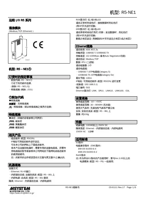
远程 I/O R5 系列通信模块机型: R5-NE1① ①在下列代码中选择。
(例如: R5-NE1/Q)・特殊规格 (例如: /C01)①附加代码◆特殊规格未填写:无特殊规格/Q:特殊规格(请从特殊规格之项另行选择)/C01: 硅涂层/C02: 聚氨酯涂层/C03: 橡胶涂层 IP地址可用组态软件进行设定。
可在本公司的网站上下载组态软件。
将本产品连接到电脑时,需要专用的连接电缆线。
所需专 用电缆线的型号请参照本公司网站的下载网站或组态软件 的使用说明书。
注)此软件的运作状况是在日文版与英文版OS上确认的。
・Ethernet: RJ-45接口・内部通信总线: 连接到底座 (机型: R5-BS) 上・内部电源: 由底座 (机型: R5-BS) 提供隔离: Ethernet-内部通信总线・内部电源间RUN显示灯: 红/绿2色LED通信正常时亮绿色灯;接收数据时亮红色灯(用DIP开关进行切换)ERR显示灯: 红/绿2色LED通信异常时绿色灯亮灯/闪烁;发送数据时,亮红色灯(用DIP开关进行切换)数据占有区设定: 用侧面的DIP开关设定占有区1或占有区2传输类型: 10BASE-T/100BASE-TX传输速度: 10/100Mbps (备有Auto Negotiation功能)通信协议: Modbus/TCP数据: RTU (二进制)通信链接数: 2个通信电缆线:・10BASE-T (STP电缆线Category 5)・100BASE-TX (STP电缆线Category 5e)最长节段: 100mIP地址: 可用组态软件 (机型: R5CON) 进行变更(初始值: 192.168.0.1)端口编号: 502Ethernet显示灯: LINK、DPLX、LINK10、LINK100、COL使用湿度范围: 30~90%RH (无冷凝)使用大气条件: 无腐蚀性气体和严重尘埃安装: 安装在底座 (机型: R5-BS) 上重量: 约100g隔离强度: Ethernet-内部通信总线・内部电源间1500V AC 1分钟电磁兼容指令(EMC指令) EMI EN 61000-6-4 EMS EN 61000-6-2RoHS指令注) 作为符合EU指令的产品使用时,要与Ver.2.00以上的电源模块 (机型: R5-PS) 一起使用。
RTU-EN01Modbus TCP远程I/O通讯模块操作手册DVP-0213910-01Modbus TCP 远程I/O 通讯模块 RTU-EN01DVP-PLC操作手册 1注意事项3 此操作手册提供功能规格、安装、基本操作与设定内容的介绍。
3 本机为开放型 (OPEN TYPE) 机壳,因此使用者使用本机时,必须将其安装于具防尘、防潮及免于电击/冲击意外的外壳配线箱内。
另必须具备保护措施 (如:特殊的工具或钥匙才可打开) ,防止非维护人员操作或意外冲击本体,造成危险及损坏,且请勿在上电时触摸任何端子。
3 请务必仔细阅读使用手册,并依照手册指示进行操作,以免造成产品受损,或导致人员受伤。
目录1 RTU-EN01简介 (3)1.1功能介绍......................................................................................................................................3 1.2功能规格......................................................................................................................................3 2 产品外观及各部介绍 (5)2.1外观尺寸......................................................................................................................................5 2.2各部介绍......................................................................................................................................5 2.3指示灯说明..................................................................................................................................6 2.4RUN/STOP 开关..........................................................................................................................6 2.5RJ-45接脚定义...........................................................................................................................6 2.6RS-232接脚定义.........................................................................................................................6 2.7 RS-485接脚定义. (6)3 安装及配线 (7)3.1安装RTU-EN01与Slim I/O 模块................................................................................................7 3.2安装RTU-EN01及其Slim I/O 模块于导轨..................................................................................7 3.3 连接网络.. (7)4 RTU-EN01寄存器与继电器 (8)4.1基本寄存器BR (Basic Register)一览表.......................................................................................8 4.2控制寄存器BR 内容说明.............................................................................................................9 4.3外部输入继电器RX...................................................................................................................12 4.4外部输出继电器RY...................................................................................................................12 4.5I/O 模块控制寄存器RCR...........................................................................................................13 4.6定时器(Timer) – T 字节装置(WORD)与有效位(BIT)..................................................................13 4.7计数器(Counter) – C 字节装置(WORD)与有效位(BIT)..............................................................14 4.8 万年历R (BIT) (15)5 MODBUS 通讯标准 (15)Modbus TCP 远程I/O 通讯模块 RTU-EN01DVP-PLC 操作手册2 5.1支持的Function Code...............................................................................................................15 5.2支持的Exception Code.............................................................................................................16 5.3组件类型及组件地址.................................................................................................................16 6 软件设定 (16)6.1DCISoft 通讯设定及搜寻通讯模块.............................................................................................16 6.2记录IP 地址..............................................................................................................................19 6.3基本设定...................................................................................................................................19 6.4网络设定...................................................................................................................................21 6.5时间设定功能............................................................................................................................23 6.6IP 过滤......................................................................................................................................24 6.7Smart PLC 设定 – IF-THEN.....................................................................................................24 6.8Smart PLC 设定 – 定时器........................................................................................................25 6.9 Smart PLC 设定 – 计数器.. (26)6.10 Smart PLC 设定 – 万年历 (27)6.11 模拟量输入/输出模块 (28)6.12 I/O 监视功能设定表 (30)6.13 Gateway 功能设定表 (31)6.14 虚拟串行端口 (34)6.15 安全设定 (36)6.16 回归出厂设定值 (37)6.17 Web 功能 (38)7 应用范例 – DCISOFT (43)7.1Smart PLC – IF-THEN..............................................................................................................43 7.2Smart PLC – 定时器................................................................................................................45 7.3Smart PLC – 计数器................................................................................................................46 7.4Smart PLC – 万年历................................................................................................................47 7.5 虚拟串行端口应用 (48)Microsoft® 和 Windows Internet Explorer® 为 Microsoft Corporation 于美国与其它国家的注册商标或商标。
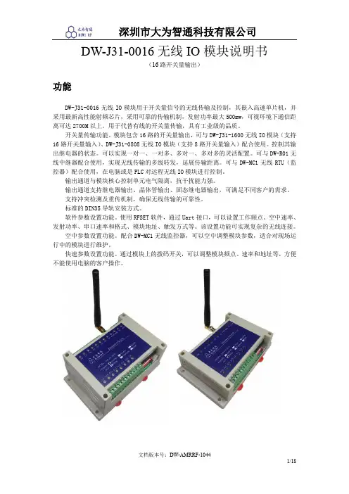
DW-J31-0016无线IO模块说明书(16路开关量输出)功能DW-J31-0016无线IO模块用于开关量信号的无线传输及控制,其嵌入高速单片机,并采用最新高性能射频芯片,采用可靠的传输机制,发射功率最大500mw,可视环境下通信距离可达2700M以上。
用于代替有线的开关量传输,具有工业级的品质。
开关量传输功能。
模块包含16路的开关量输出,可与DW-J31-1600无线IO模块(支持16路开关量输入)、DW-J31-0808无线IO模块(支持8路开关量输入)配合使用。
控制其输出继电器的状态。
可以实现一对一、一对多、多对一、多对多的灵活配置。
可与DW-R01无线中继器配合使用,实现无线传输的多级转发,延展传输距离。
可与DW-MC1无线RTU(监控器)配合使用,在电脑或是PLC对远程无线IO模块进行控制。
输出通道与模块核心控制单元电气隔离,抗干扰能力强。
输出通道支持继电器输出、晶体管输出、固态继电器输出,可满足不同客户的需求。
支持冲突检测及重传机制,确保无线传输的可靠性。
标准的DIN35导轨安装方式。
软件参数设置功能。
使用RFSET软件,通过Uart接口,可以设置工作频点、空中速率、发射功率、串口速率和格式、模块地址、触发方式等。
该设置功能可实现复杂的无线连接。
空中参数设置功能。
配合DW-MC1无线监控器,可以空中调整模块参数,适合对现场运行中的模块进行维护。
快速参数设置功能。
通过模块上的拨码开关,可以调整模块频点、速率和地址等,方便不能使用电脑的客户操作。
应用远程开关如下图所示,远程开关SW2将始终与本地开关SW1保持一致的状态。
一对多控制如下图所示,模块1的开关SW1-1可远程控制模块2的开关SW2-1;模块1的开关SW1-2可远程控制模块2的开关SW3-1;模块1的开关SW1-3可远程控制模块4的开关SW4-1. 模块1是DW-J31-1600,模块2、3、4可以是DW-J31-0016(16路开关量输出)或是DW-J31-0808(8路开关量输出)多对多控制如下图所示,模块1的开关可远程控制模块3、4的继电器输出;同时模块2的开关可远程控制模块3、4的继电器输出。
io模块的使用方法io模块是Python中用于进行输入输出操作的标准库之一,它提供了一系列函数和类,方便我们进行文件读写、网络通信等操作。
本文将介绍io模块的使用方法。
一、文件读写1. 打开文件使用open函数可以打开一个文件,并返回一个文件对象。
open函数的第一个参数是文件路径,第二个参数是打开模式。
常用的打开模式有:- 'r':只读模式,文件必须存在- 'w':写入模式,如果文件不存在则创建,如果文件存在则清空内容- 'a':追加模式,在文件末尾添加内容,如果文件不存在则创建- 'x':独占创建模式,只能创建新文件,如果文件已存在则报错例如,要打开一个名为"test.txt"的文件,可以使用以下代码:```pythonfile = open("test.txt", "r")```2. 读取文件内容文件对象有多种读取内容的方法,常用的有:- read(size):读取指定大小的内容,如果不指定大小则读取整个文件内容- readline():读取一行内容- readlines():读取所有行,并返回一个列表,每行作为列表的一个元素示例代码:```pythonfile = open("test.txt", "r")content = file.read()print(content)```3. 写入文件内容文件对象有多种写入内容的方法,常用的有:- write(str):写入字符串- writelines(lines):写入多行,参数是一个字符串列表示例代码:```pythonfile = open("test.txt", "w")file.write("Hello, world!")file.close()```二、网络通信1. TCP通信io模块提供了socket类,可以用于进行TCP通信。
PNL16远程IO模块安装使用说明书手册简介本手册适用于昆山兴威联电气有限公司所生产的PNL16远程I0模块本手册主要介绍了PNL16远程I0模块的硬件特性、安装方法、主要功能及配置过程阅读对象本手册适合下列人员阅读电气工程师现场装配人员相关约定本手册采用了如下几种醒目标志来表示操作过程中应该注意的地方,这些标志的意义如下:该图标表示需引起重视的警告事项。
该图标表示提醒操作中应注意的事项,如果操作错误可能导致设备损坏等不良后果。
该图标表示对操作内容的描述进行必要的补充和说明。
版权声明昆山兴威联电气有限公司版权所有,并保留对本手册及本声明的最终解释权和修改权。
本手册的版权归昆山兴威联电气有限公司所有。
未得到昆山兴威联电气有限公司的书面许可,任何人不得以任何方式或形式对本手册内的任何部分进行复制、摘录、备份、修改、传播、翻译成其它语言、将其全部或部分用于商业用途。
免责声明本手册依据现有信息制作,其内容如有更改,恕不另行通知。
昆山兴威联电气有限公司在编写该手册的时候已尽最大努力保证其内容准确可靠,但昆山兴威联电气有限公司不对本手册中的遗漏、不准确或印刷错误导致的损失和损害承担责任。
商标声明为昆山兴威联电气有限公司注册商标。
本手册提及的所有商标,由各自所有人拥有。
发行版本:V2.0第一章:产品介绍1.1 产品简介PNL16系列远程IO模块是昆山兴威联电气有限公司自主研发符合Profinet V2.3通讯协议的16通道工业数字输入输出模块。
本系列产品采用M12 T Code编码连接器供电,与传统的7/8"连接器相比,不但可以提供更大的电流(12A),更是可以节约宝贵的现场安装空间。
1.2 外观及安装尺寸1.3 端口介绍1.3.1 网络及电源针脚定义C0/C2/C4/C6C1/C3/C5/C7脚位 ETH(以太网)PWR(电源)1TD+(黄,与RJ45 1脚连接) 24V( US+ ) 2 RD+(白,与RJ45 3脚连接) GND( UA- ) 3 TD-(橙,与RJ45 2脚连接) GND( US- ) 4RD-(蓝,与RJ45 6脚连接)24V( UA+ )1.3.2 I/O 信号A 编码母头针脚定义 PIN 位说明1 24V ( PN16DO未使用)2 PIN 2信号3 GND4 PIN 4信号5FEC0C2C4C61.4 指示灯说明1.4.1 以太网及电源指示灯1.4.2 I/O 信号指示灯指示灯 颜色 含义 状态 说明2 绿色 对应端口PIN 2信号 绿色 端口PIN 2有信号 熄灭 端口PIN 2无信号 4绿色对应端口PIN4信号绿色 端口PIN 4有信号 熄灭端口PIN 4无信号第二章:安装说明2.1 相关配件订购I/O 接口M12 A 编码公头螺钉接线圆形连接器 912701PWR INM12 T 编码公头螺钉接线圆形连接器 912744PWR OUTM12 T 编码母头螺钉接线圆形连接器 912932ETH 接口M12 D 编码公头螺钉接线圆形连接器 914521I/O 接口M12 Y 型分支器 941121PWR INM12 T 编码母头预制线缆屏蔽、固定安装:913344-902-xxxx 屏蔽、拖链抗扭:913344-901-xxxx 非屏蔽、固定安装:912344-960-xxxxPWRM12 T 编码公母对接预制线缆屏蔽、固定安装:943044-902-xxxx 屏蔽、拖链抗扭:943044-901-xxxx 非屏蔽、固定安装:942044-960-xxxxETHM12 D 编码公公对接预制线缆固定安装:944511-790-xxxx 拖链抗扭:944511-796-xxxxM12母端口保护盖996050标识片2 plates = 10 pieces999006更多配件请访问我们的网站 或者联系我们的业务人员2.2 连接说明2.2.1 设备接地为避免数据损坏或丢失,请确保设备接地良好2.2.2 网线屏蔽为避免网络数据损坏或者丢失,请使用专用的Profinet网线,并保证网线的屏蔽层接地良好。

GL-EXT600W智能无线IO模块说明书一、产品介绍............................................................................................................................... 错误!未定义书签。
二、硬件连接............................................................................................................................... 错误!未定义书签。
1、前面板布局....................................................................................................................... 错误!未定义书签。
2、模拟量输入接口............................................................................................................... 错误!未定义书签。
3、开关量输入接线方式....................................................................................................... 错误!未定义书签。
4、开关量输出接线方式....................................................................................................... 错误!未定义书签。
8 Point Digital Input/OutputM12User GuideTrademark NoticesOther product names mentioned herein may be trademarks and/or registered trademarks of their respective owners.First Edition, August 3, 2018Copyright © 2018. Comtrol Corporation.All Rights Reserved.Comtrol Corporation makes no representations or warranties with regard to the contents of this document or to the suitability of the Comtrol product for any particular purpose. Specifications subject to change without notice. Some software or features may not be available at the time of publication. Contact your reseller for current product information.Document Number: 2000652 Rev. ATable of Contents Overview (5)IOLB-8318 Module Overview (5)8 Digital In or Output (24VDC) (5)IOLB-8318 LEDs (6)IOLB-8318 Technical Specifications (7)IO-Link Basics (8)Hardware Installation (11)Mounting the IOLB-8318 (11)Connecting the IOLB-8318 (12)IOLB-8318 Power Supply Requirements (12)Installation With an IP67 Class A IO-Link Master (13)Installation With a Class A IP20 IO-Link Master (16)Digital In-/Outputs (M12) (17)Comtrol IO-Link Master Diagnostic Page (18)Configuring the IOLB-8318 (19)Locating the IOLB-8318 IODD Files (19)Loading the IODD Files Onto the Comtrol IO-Link Master (19)Configuring the IOLB-8318 (23)Technical Data Overview (27)Input Debouncing and Input Signal Extension (27)Object Descriptions (29)IOLB-8318 Parameters (29)Diagnostics Parameters (30)IOLB-8318 User Guide: 2000652 Rev. A Table of Contents - 34 - Table of Contents IOLB-8318 User Guide: 2000652 Rev. AOverviewIOLB-8318 Module Overview.The IOLB-8318 has eight digital points, each of which can be operated as an input or as an output and is connected to an IO-Link Master. Each point is configurable in that it can be used either as an input or output; the input circuit is internally connected to the output driver, so that a set output is displayed automatically in the input process image.The outputs handle load currents of up to 0.5 A, and although the total current is limited to 4 A, they are short-circuit proof and protected against inverse polarity. The state of each signal is indicated by means of light emitting diodes. The signals are connected via M12 connectors.The small IOLB-8318 form factor (H126 x W30 x D26.5 mm) means that they are suitable for use where space is at a premium. The small mass of the IOLB-8318 module facilitates applications with mobile I/O interface, for example, a robot arm.The robust design of the IOLB-8318 module enables them to be used directly at the machine. Control cabinets and terminal boxes are now no longer required. The module is fully sealed and therefore ideally prepared for wet, dirty or dusty conditions (IP67).Pre-assembled cables significantly simplify IO-Link and signal wiring. Very few wiring errors are made, so that commissioning is optimized. In addition to pre-assembled IO-Link, power and sensor cables, field- configurable connectors and cables are available for maximum flexibility. Sensors and actuators are connected through M12 connectors.8 Digital In or Output (24VDC)The IOLB-8318 has eight digital points, each of which can be operated as an input or as an output. You do not need to configure a point as input or output in software because the input circuit is internally connected to the output driver, so a set output is displayed automatically to the input process image.The outputs handle load currents of up to 0.5 A, are short-circuit proof and protected against inverse polarity.The filter constant of the inputs is 3.0 ms.The state of each signal is indicated with LEDs.Note:The connected sensors are powered via 2L+, not from L+. The IOLB-8318 supplies digital sensors in contrastto many other modules from the additional supplyvoltage 2L+, not from the voltage L+. This happensbecause the connectors can be used alternatively asinput or as output. If an overload of the sensor supply(current > 0.5 A) occurs, the 24V LED is red.If the 2L+ supply power of the IOLB-8318 is switched through an E-Stop or similar circuit safety circuit – DO NOT externally power any of the devices connected to the IOLB-8318 since they could supply power to the IOLB-8318 and the outputs of the IOLB-8318 could still be powered even after2L+ is de-energized.IOLB-8318 User Guide: 2000652 Rev. A Overview - 56 - Overview IOLB-8318 User Guide : 2000652 Rev. AIOLB-8318 LEDsIOLB-8318 LEDsThis subsection provides information about the IOLB-8318 LEDs.X1 (IO-Link LED)DescriptionOffIO-Link communications not active.Flashing green (1 Hz)IO-Link communications active.Lit (Red)Short circuit on C / Q line or overheating.Power Supply LEDsDescription24V (L+)OffVoltage L+ Unavailable Green Voltage L+ Ok Red Voltage L+ Too Low 24 (2L+)OffVoltage 2L+ Unavailable Green Voltage 2L+ OkRedVoltage 2L+ Too Low, Short CircuitIOLB-8318 Technical Specifications IOLB-8318 Technical SpecificationsIOLB-8318 Technical SpecificationsCommunication IO-LinkData transfer rate230.4 KBaud (COM3)IO-Link connection 1 x M12 connector, A-codedSpecification version IO-Link V1.1, Class BRequirements IO-Link Master V1.1Number of outputs0 to 8Output connector M12Load type Ohmic, inductive, lamp loadRated output voltage24VDC (-15%/+20%)Output current Max. 0.5 A each pointShort circuit current Max. 1.5 AModule electronic current consumption Typically 100 mA from L+Output driver current consumption Typically 20 mAModule electronic supply L+Output driver supply2L+ (Port Class B wiring)Number of inputs0 to 8Input connections M12Nominal input voltage24VDC (-15%/+20%)Input filter (adjustable) 3.0 ms (default), adjustable between 0 ms and 20 ms Input signal extension time (adjustable)0 ms (default), adjustable between 0 ms and 100 ms "0" signal voltage-3...+5 V (EN 61131-2, Type 3)"1" signal voltage+11...+30 V (EN 61131-2, Type 3)Input current Typically 3 mA (EN 61131-2, Type 3)Sensor supply U S1 (derived from L+)Process image8 input bits, 8 output bitsPermissible ambient temperature during operationNote:To meet the UL requirements, the IOLB-8318-25°C to +60°Chas to be operated only at an ambienttemperature range of 0 to 55°C!IOLB-8318 User Guide: 2000652 Rev. A Overview - 78 - Overview IOLB-8318 User Guide : 2000652 Rev. AIO-Link BasicsIO-Link BasicsIO-Link is a communications system for connecting intelligent sensors and actuators to an automation system in IEC 61131-9 under the name Single-drop digital communication interface for small sensors and actuators (SDCI). Both the electrical connection data and the communication protocol are standardized and in the IO-Link specification summarized.The IOLB-8318 meets the IO-Link specification 1.1. The IO-Link specification is included in the IEC standards and is accepted as IEC 61131-9 in an extended form. In this case, the new designation voltage SDCI is introduced.An IO-Link system consists of an IO-Link Master, one or more IO-Link devices and sensors or actuators. The IO-Link Master provides the interface to the higher-level controller and controls the communication with the connected IO-Link devices. The Comtrol IO-Link Master series has four or eight IO-Link ports at which each one IO-Link device can be connected. Therefore, IO-Link is not a fieldbus, but rather is a peer-to-peer connection as shown in the figure below.The connected IO-Link devices have individual parameter information detected during automatic scanning with the Comtrol IO-Link Master. Refer to Configuring the IOLB-8318 on Page 19 for more information.Permissible ambient temperature during storage -40°C to +85°CVibration / shock resistance Conforms to EN 60068-2-6 / EN 60068-2-27EMC resistance/emission Conforms to EN 61000-6-2 / EN 61000-6-4Protection classIP65, IP66, IP67 (conforms to EN 60529)IOLB-8318 Technical SpecificationsIOLB-8318 User Guide : 2000652 Rev. A Overview - 9IO-Link BasicsThe structure of the IO-Link communication is shown in the following figure. In particular, this represents the sequence in the automatic scanning of the IO-Link ports.The Pre-operate State occurs if the IO-Link device is v1.1 and if Data Storage is enabled then the deviceparameters are uploaded or downloaded.IO-Link Basics10 - Overview IOLB-8318 User Guide: 2000652 Rev. AIOLB-8318 User Guide : 2000652 Rev. A Hardware Installation - 11Hardware Installation This section provides installation information for the IOLB-8318.Mounting the IOLB-8318The following table provides information that you may require for installation.Note:While mounting the IOLB-8318, protect all connectors against contamination. All connectors must have either a cable or plug to guarantee IP67 rating.Keep the following in mind when mounting the IOLB-8318.•Mount the IOLB-8318 with two M3 bolts. •The bolts must be longer than 15 mm. The fixing holes of the modules are not threaded.•When assembling, remember that the connectors increases the overall height.IOLB-8318Housing materialPA6 (polyamide)Casting compoundPolyurethane Mountingtwo fastening holes Ø 3 mm for M3Metal partsBrass, nickel-plated ContactsCuZn, gold-plated Power feed through (maximum)4 A Installation positionAny Protection classIP65, IP66, IP67 (conforms to EN 60529)Dimensions (H x W x D)126 x 30 x 26.5 mm Weight Approximately 125 g12 - Hardware Installation IOLB-8318 User Guide : 2000652 Rev. A Connecting the IOLB-8318Connecting the IOLB-8318Use the appropriate procedure to connect the IOLB-8318 to an IO-Link Master.•Installation With an IP67 Class A IO-Link Master on Page 13•Installation With a Class A IP20 IO-Link Master on Page 16IOLB-8318 Power Supply RequirementsThe power supply and safety circuit that you connect to the IOLB-8318 must meet the following requirements:•24VDC supplied by an isolating source and protected by means of a fuse (in accordance with UL248),rated maximum 4A or a 24VDC power source that satisfies NEC Class 2.•A NEC Class 2 power supply shall not be connected in series or parallel with another (Class 2) power source.•To meet the UL requirements, the IOLB-8318 must not be connected to unlimited power sources!Note:To meet the UL requirements, the IOLB-8318 must not be connected to telecommunications networks and must be operated at the ambient temperature range specified in the specifications.For additional information, see IOLB-8318 Technical Specifications on Page 7.The connected sensors are powered via 2L+, not from L+. The IOLB-8318 supplies digital sensors in contrast to many other modules from the additional supply voltage 2L+, not from the voltage L+. This happens because the connectors can be used alternatively as input or as output. If an overload of the sensor supply (current > 0.5 A) occurs, the 24V LED is red.If the 2L+ supply power of the IOLB-8318 is switched through an E-Stop or similar circuit safety circuit – DO NOT externally power any of the devices connected to the IOLB-8318 since they could supply power to the IOLB-8318 and the outputs of the IOLB-8318 could still be powered even after 2L+ is de-energized.The following Comtrol cables and M12 Y-splitter can be used to connect the IOLB-8318 to the Class A IP67 IO-Link Master models.Note:It is recommended to pull the M12 connectors tight with a nut torque of 0.6 Nm.PinInput - Male 124V (L+) - electronics power 224V (2L +) - sensor or device power 3GND (L-)4IO-Link (C/Q)5GND (2M)Comtrol Part NumberDescription 1200143Y Splitter, M12 5-poles, A-Coded, M to 2F Varies by length †Sensor cable, M12 5-poles, A-coded, M to F Varies by length †Power Cable, Comtrol IOLB, M12 A-Coded, M to wires† Contact Comtrol Sales for the part number.Installation With an IP67 Class A IO-Link Master Installation With an IP67 Class A IO-Link MasterUse the following procedure to connect the IOLB-8318 to a Class A IP67 IO-Link Master.The images in this subsection showsconnecting the 8-port IP67 model. Please note that the same procedures work for the 4-port model.Note:This procedure assumes that the IO-Link Master is powered on,connected to the network and theIP address has beenprogrammed for yourenvironment.1.Connect the M12 Y splitter to anavailable Comtrol IO-Link MasterIO-Link port.This image shows:•IO-Link sensor cable connected between the IO-Link Masterport and the Y Splitter(1200143).•Y Splitters connected directly to Ports 4 and 5.IO-Link MasterPower CableIO-Link MasterEthernet CableThe Y Splitter can beconnected directlyto an IO-Link Masterport or an IO-Linksensor cable.IOLB-8318 User Guide: 2000652 Rev. A Hardware Installation - 13Installation With an IP67 Class A IO-Link MasterNote:In the next step, make sure that the 24V power supply or switched through an E-Stop or similar circuit safety circuit is not energized during the wiring.2.Connect the white and green wires of the Comtrol IOLB power cable to aU a power source.a.Connect the white wire to the positive 24V terminal.b.Connect the green wire to the negative 24V terminal.3.Connect the M12 connector end of the Comtrol IOLB power cable to PortB on the Y-Splitter.Note:Connectors A and B are interchangeable on the Y Splitter.Green =NegativeWhite =PositivePowerCable toPort B onthe YSplitter14 - Hardware Installation IOLB-8318 User Guide: 2000652 Rev. AIOLB-8318 User Guide : 2000652 Rev. A Hardware Installation - 15Installation With an IP67 Class A IO-Link Master4.Connect the 5-pole (M12) sensor cable between Port A on the Y-splitter and the IOLB-8318 IO-Link Port X1.5.Apply power to the U a power source connected to the IOLB-8318.6.Verify that the following LEDs are lit:•Green 24V (L+) and 24V (2L+) LEDs on the IOLB-8318•Green IO-Link on the Comtrol IO-Link Master is lit •Amber DI LED on the Comtrol IO-Link Master flickers because power is being injected into the DI pin to power the IOLB-8318.Note:Refer to IOLB-8318 LEDs on Page 6 for detailedLED information.16 - Hardware Installation IOLB-8318 User Guide : 2000652 Rev. A Installation With a Class A IP20 IO-Link MasterInstallation With a Class A IP20 IO-Link MasterUse the following procedure to connect the IOLB-8318 to a Class A IP20 (DIN rail model) IO-Link Master.Note:This procedure assumes that the IO-Link Master is powered on, connected to the network and the IP address has been programmed for your environment.1.Connect a M12 A-coded to bare wire cable to the IO-Link Master:•Black to C/Q •Blue to L-•Brown to L+Note:In the next step, make sure that the 24V power supply or switched through an E-Stop or similar circuit safety circuit is not energized during the wiring.2.Connect the white and green wires of the IO-Link cable to a U a power source. The image belowillustrates connecting to a power supply.c.Connect the white wire to the positive 24V terminal.d.Connect the green wire to the negative 24V terminal.e.Apply power to the U apower source.3.Connect the M12 connector from the IO-Link Master to the IOLB-8318 X1 connector.The white (positive) and green (negative) wires can be connected to a 24V power supply or switched through an E-Stop or safety circuit.Digital In-/Outputs (M12) 4.Verify that the following LEDs are lit:LEDs on the IOLB-8318•Green IO-Link on the Comtrol IO-Link Master is litNote:Refer to IOLB-8318 LEDs on Page6 for detailed LED information.Digital In-/Outputs (M12)Each of the points of the IOLB-8318 optionally operated as an input or as an output.The digital inputs acquire the binary control signals from the process level and transmit them to the higher- level automation unit. The digital outputs connect the binary control signals from the automation unit on to the actuators at the process level.The signals are connected via screw-in M12 connectors. The inputs/outputs indicate their status through lightemitting diodes.The outputs are protected against short-circuits and the inputs are protected against reverse voltage.IOLB-8318 User Guide: 2000652 Rev. A Hardware Installation - 17Comtrol IO-Link Master Diagnostic PageComtrol IO-Link Master Diagnostic PageYou can also verify the IOLB-8318 operation by viewing the Comtrol IO-Link Master IO-Link Diagnostics page.1.Log into the Comtrol IO-Link Master using the IP address.2.Click Diagnostics | IO-Link.18 - Hardware Installation IOLB-8318 User Guide: 2000652 Rev. AConfiguring the IOLB-8318This section discusses loading the IODD on the Comtrol IO-Link Master.Locating the IOLB-8318 IODD FilesThe IOLB-8318 IODD files are located on the Comtrol download site using one of these addresses:•http: ///IO_Link_Block/IOLB-8318/IODD/•ftp:///IO_Link_Block/IOLB-8318/IODD/Loading the IODD Files Onto the Comtrol IO-Link MasterUse the following procedure to load the IOLB-8318 IODD file.1.If necessary, download the IOLB-8318 IODD files.2.Log into the Comtrol IO-Link Master using the IP address.3.Click Attached Devices.button.4.Click the UPLOAD FILEIOLB-8318 User Guide: 2000652 Rev. A Configuring the IOLB-8318 - 19Loading the IODD Files Onto the Comtrol IO-Link Master5.Click the CHOOSE FILE button.button.7.Click the UPLOAD20 - Configuring the IOLB-8318IOLB-8318 User Guide: 2000652 Rev. ALoading the IODD Files Onto the Comtrol IO-Link Master 8.Click the Ok button.Optionally, click the file name if you want to view the xml file.9.IOLB-8318 User Guide: 2000652 Rev. A Configuring the IOLB-8318 - 21Loading the IODD Files Onto the Comtrol IO-Link Master10.Click the SUMMARYlink to verify that the correct IODD file loaded.22 - Configuring the IOLB-8318IOLB-8318 User Guide: 2000652 Rev. AIOLB-8318 User Guide : 2000652 Rev. A Configuring the IOLB-8318 - 23Configuring the IOLB-8318Configuring the IOLB-8318After loading the IODD file, you are ready to configure the points on the IOLB-8318.1.If necessary, log into the Comtrol IO-Link Master.2.Click Attached Devices | Port x, where x is the IO-Link port that you have attached the IOLB-8318.3.Click the EDIT button.Note:For information about using the Comtrol IO-Link Master, refer to the help system or appropriate UserGuide for the model.Configuring the IOLB-83184.Make the necessary changes to reflect the devices that you intend on connecting and click the SAVEbutton.24 - Configuring the IOLB-8318IOLB-8318 User Guide: 2000652 Rev. AConfiguring the IOLB-8318 After the page is saved, note that the changes have been implemented.IOLB-8318 User Guide: 2000652 Rev. A Configuring the IOLB-8318 - 25Configuring the IOLB-831826 - Configuring the IOLB-8318IOLB-8318 User Guide: 2000652 Rev. AIOLB-8318 User Guide : 2000652 Rev. A Technical Data Overview - 27Technical Data OverviewThis section provides supporting information for the IOLB-8318.Input Debouncing and Input Signal ExtensionThe IOLB-8318 supports a configurable input debouncing and a variable input signal extension for all digital inputs. This can be set through Index 2048. The set value applies for all digital inputs.The value decides the delay with which the input value is transfered to the higher-level control. Impulses that are smaller than the filter time will be ignored. In the figure below function examples are presented with a filter time of 10 ms.Input filter: Variable Adjustable Over DeviceParameter (Index 2048 Subindex 1)ValueFiltertime [ms]0010.52331042028 - Technical Data Overview IOLB-8318 User Guide : 2000652 Rev. AInput Debouncing and Input Signal Extension.When the filtered input signal transitions either off/on or on/off a minimum pulse width of the value selected in the table above will be generated to the process data.Input Signal Extension Time: Variable Adjustable Over Device Parameter (Index 2048 Subindex 2)ValueInput Signal Extension Time [ms]0010.5233104205506100Object DescriptionsThis section provides supporting information for the IOLB-8318 object descriptions.IOLB-8318 ParametersNote:The Index and Sub-indexes are displayed as decimal numbers, which match the Comtrol IO-Link Master.Index Subindex Name Meaning Data type Flags DefaultIDENTIFICATION16Vendor Name Comtrol Corporation StringT64RO N/A17Vendor Text StringT64RO N/A18Product Name Comtrol IOLB-8318StringT64RO N/A20Product Text 8-Ch Configurable Digital Input/Output Module, M12StringT64RO N/A21Serial Number9657-XXXXXX StringT16RO N/A 22Hardware Version00StringT64RO N/A 23Firmware Version04StringT64RO N/A24ApplicationSpecific Tag*******************StringT32RO N/APARAMETER204801Input Filter 0: Off1: 0.5ms2: 3ms3: 10ms4: 20msRecordT8RW0x0020 (2dec)204802Signal Extension0: Off1: 0.5ms2: 3ms3: 10ms4: 20ms5: 50ms6:100msRecordT8RW0x0000 (0dec) MISCELLANEOUS SETTINGS2StandardCommand130 - Restore factory defaults UINT8WO0x0000 (0dec)1202Data Storage Lock BOOLEAN RW0x0000 (0dec)IOLB-8318 User Guide: 2000652 Rev. A Object Descriptions - 29Diagnostics ParametersDiagnostics ParametersIndex Subindex Name Meaning Data type FlagsDIAGNOSTICS256001Overtemperature Temperature exceeded limits RecordT RO256002Short detected Short detected RecordT RO256003US low US power low RecordT RO256004UA low UA power low RecordT RO256005UA stat UA state RecordT RO30 - Object Descriptions IOLB-8318 User Guide: 2000652 Rev. A。
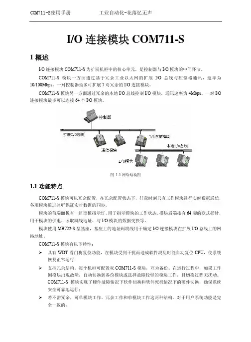
I/O连接模块COM711-S1概述I/O连接模块COM711-S为扩展机柜中的核心单元,是控制器与I/O模块的中间环节。
COM711-S模块一方面通过基于冗余工业以太网的扩展I/O总线与控制器通讯,速率为10/100Mbps。
一对控制器最多可扩展7对冗余的I/O连接模块。
COM711-S模块另一方面通过冗余的本地I/O总线控制I/O模块,通讯速率为4Mbps。
一对I/O 连接模块最多可以连接64个I/O模块。
图 1-1网络结构图1.1功能特点COM711-S模块可以冗余配置,在冗余配置状态下,任意时刻只有工作模块进行实时数据通信,备用模块通过监听保证实时数据的同步。
模块的前端面板有一组面板指示灯,用于指示模块的工作状态。
模块后端接有64脚的欧式插针,用于模块的供电、读取跳线地址、与I/O模块的数据交换等。
模块使用MB722-S型基座,基座上的地址码跳线用于确定I/O连接模块在扩展I/O总线上的网络地址。
COM711-S模块有以下特性:¾具有WDT看门狗复位功能,在模块受到干扰而造成软件混乱时能自动复位CPU,使系统恢复正常运行;¾支持冗余结构。
每个机柜可配置双COM711-S模块,互为备份。
在运行过程中,如果工作侧模块出现故障,自动切换到备份模块或选择故障较轻的模块工作,且切换过程无扰动。
COM711-S模块实现了硬件故障情况下软件切换和软件死机情况下的硬件切换,确保系统安全可靠地运行;¾若不需冗余,可单模块工作。
冗余工作和单模块工作这两种结构,对于用户系统功能是完全一致的;¾采用冗余工业以太网,和控制器通讯使用硬件组播方式进行,大大降低了网络负荷,提高系统的响应速度;¾允许上位机使用故障诊断软件进行故障诊断;¾具有地址冲突检测、断线检测、I/O通道故障检测等自诊断功能;¾模块运行温度为(0~50)℃,宽温型为(-20~70)℃;贮存温度为(-40~70)℃;运行湿度为10%RH~90%RH,无凝露;贮存湿度为5%RH~95%RH,无凝露。
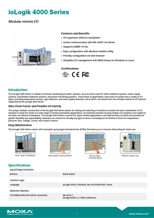
ioLogik4000SeriesModular remote I/OFeatures and Benefits•I/O expansion without a backplane•Active communication with MX-AOPC UA Server•Supports SNMP v1/v2c•Easy configuration with Modular ioAdmin utility•Friendly configuration via web browser•Simplifies I/O management with MXIO library for Windows or LinuxCertificationsIntroductionThe ioLogik4000Series is suitable for remote monitoring and alarm systems,such as those used for water treatment systems,water supply systems,wastewater treatment systems,and power monitoring systems.These kinds of applications need more I/O points and a variety of I/O types,including temperature sensors,gas detectors,and water quality detectors,all of which can benefit from the versatile mixture of I/O features supported by the ioLogik4000Series.Slice Form Factor and Flexible I/O VarietyThe unique modular construction of the ioLogik4000Series allows for mixing and matching of modules to achieve the best combination of I/O modules to meet the needs of a wide range of remote automation applications.An industrial modular housing enables I/O modules to be added to the base unit without a backplane.The ioLogik4000Series is perfect for space-limited applications,and high-density I/O points are provided for greater flexibility and expandability.Modules can connect to virtually any type of sensor,including but not limited to those for temperature, pressure,flow,voltage,current,and contact closure.Easy MaintenanceThe ioLogik4000Series comes with removable spring-type terminal blocks(RTBs)that allow you to conserve field wiring for future use.SpecificationsInput/Output InterfaceButtons Reset buttonControl LogicLanguage ioLogik E4200:Click&Go,NA-4010/4020/4021:NoneEthernet Interface10/100BaseT(X)Ports(RJ45connector)NA-4010:1ioLogik E4200:2,2MAC addressesEthernet Software FeaturesConfiguration Options NA-4010/ioLogik E4200:Web Console(HTTP)NA-4010/4020/4021:Windows Utility(ioAdmin)ioLogik E4200:Windows Utility(Modular-ioAdmin)Industrial Protocols NA-4010:Modbus TCP Server(Slave),MXIO LibraryNA-4020/4021:MXIO LibraryioLogik E4200:Modbus TCP Server(Slave),Moxa AOPC(Active Tag),MXIO Library,SNMPv1/v2c,SNMPv1TrapManagement NA-4010/ioLogik E4200:DHCP Client,HTTP,IPv4,TCP/IP,UDPNA-4010/4020/4021:ioAdminioLogik E4200:Modular-ioAdminSerial InterfaceConnector NA-4021:DB9femaleNA-4020:Terminal blockData Bits7,8No.of Ports1Parity None,Even,OddSerial Standards NA-4021:RS-232NA-4020:RS-485Stop Bits1,2Baudrate NA-4020/4021:1200,2400,4800,9600,19200,38400,57600,115200bpsSerial Software FeaturesIndustrial Protocols NA-4020/4021:Modbus RTU/ASCII SlaveSerial SignalsRS-232NA-4021:TxD,RxD,GNDRS-485-2w NA-4020:Data+,Data-,GNDDIP Switch ConfigurationSerial Interface Fixed baudrateModbus TCPMax.No.of Client Connections8Mode Client(Master)Power ParametersNo.of Power Inputs1System Power ParametersPower Connector Spring-type Euroblock terminalNo.of Power Inputs1Input Voltage11to28.8VDCPower Consumption NA-4010:60mA@24VDCNA-4020/4021:70mA@24VDCioLogik E4200:175mA@24VDCField Power ParametersPower Connector Spring-type Euroblock terminalNo.of Power Inputs1Input Voltage11to28.8VDCCurrent in Field Power Contact10A(max.)Physical CharacteristicsHousing PlasticDimensions45x99x70mm(1.77x3.90x2.76in)Weight NA-4010/4020/4021:150g(0.33lb)ioLogik E4200:180g(0.396lb)Installation DIN-rail mountingEnvironmental LimitsOperating Temperature-10to60°C(14to140°F)Storage Temperature(package included)-40to85°C(-40to185°F)Ambient Relative Humidity5to95%(non-condensing)Altitude2000m1Standards and CertificationsEMC EN61000-6-2/-6-4EMI CISPR22,FCC Part15B Class AEMS IEC61000-4-2ESD:Contact:4kV;Air:8kVIEC61000-4-3RS:80MHz to1GHz:10V/mIEC61000-4-4EFT:Power:2kV;Signal:1kVIEC61000-4-5Surge:Power:2kV;Signal:1kVIEC61000-4-6CS:10VIEC61000-4-8PFMFSafety UL508Shock IEC60068-2-27Vibration IEC60068-2-6DeclarationGreen Product RoHS,CRoHS,WEEEMTBFTime NA-4010:4,739,300hrsNA-4020:4,721,640hrsNA-4021:4,695,360hrsioLogik E4200:357,000hrsStandards Telcordia SR332WarrantyWarranty Period2yearsDetails See /warranty1.Please contact Moxa if you require products guaranteed to function properly at higher altitudes.Package ContentsDevice1x ioLogik4000Series remote I/OInstallation Kit1x terminal block,8-pin,3.81mmDocumentation1x quick installation guide(ioLogik E4200)1x warranty cardNote This product requires additional modules(sold separately)to function.DimensionsI/O Network Adapter I/O ModuleOrdering InformationModel Name Control Logic Ethernet Interface Serial Interface No.of Support I/O Modules ioLogik E4200Click&Go2x RJ45–16NA-4010–1x RJ45–32NA-4020––RS-48532NA-4021––RS-23232 Accessories(sold separately)I/O ModulesM-1450For the ioLogik4000Series,4DIs,110VACM-1451For the ioLogik4000Series,4DIs,220VACM-1600For the ioLogik4000Series,16DIs,24VDC,sink typeM-1601For the ioLogik4000Series,16DIs,24VDC,source typeM-1800For the ioLogik4000Series,8DIs,24VDC,sink typeM-1801For the ioLogik4000Series,8DIs,24VDC,source typeM-2450For the ioLogik4000Series,4relays,24VDC/230VAC,2AM-2600For the ioLogik4000Series,16DOs,24VDC,0.5A,sink typeM-2601For the ioLogik4000Series,16DOs,24VDC,0.5A,source typeM-2800For the ioLogik4000Series,8DOs,24VDC,0.5A,sink typeM-2801For the ioLogik4000Series,8DOs,24VDC,0.5A,source typeM-3802For the ioLogik4000Series,8AIs,4to20mA,12bitsM-3810For the ioLogik4000Series,8AIs,0to10V,12bitsM-4402For the ioLogik4000Series,4AOs,4to20mA,12bitsM-4410For the ioLogik4000Series,4AOs,0to10V,12bitsM-6200For the ioLogik4000Series,2AIs,RTD:PT100,JPT100M-6201For the ioLogik4000Series,2AIs,TCPower ModulesM-7001For the ioLogik4000Series,system power moduleM-7002For the ioLogik4000Series,field power moduleM-7804For the ioLogik4000Series,potential distributor module,0VDC8channelM-7805For the ioLogik4000Series,potential distributor module,24VDC,8channelSoftwareMX-AOPC UA Server OPC UA Server software for converting fieldbus to the OPC UA standard©Moxa Inc.All rights reserved.Updated Dec09,2020.This document and any portion thereof may not be reproduced or used in any manner whatsoever without the express written permission of Moxa Inc.Product specifications subject to change without notice.Visit our website for the most up-to-date product information.。

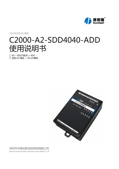
2020年8月9日 更新C2000-A2-SDD4040-ADD 使用说明书4G ⇋ 4DI(干接点) + 4DO远程 I/O 模块 — 4G I/O模块深圳市中联创新自控系统有限公司Shenzhen United Innovation Automatic Control System Co., Ltd.244455666799121315161617171717171717171717171819191919202125262729313131323344444546474849505354目录目录1. 快速使用1.1. 使用前准备1.2. 设备接线1.3. 软件设置及设备调试1.3.1. 切换 AP 模式1.3.2. 搜索 Wi-Fi 1.3.3. 设备安装1.3.4. 设备搜索及参数设置1.3.5. 设备调测2. 硬件说明2.1. 技术参数2.2. 产品外观2.3. 指示灯2.4. 端口说明2.5. 尺寸2.6. 安装方式3. 产品功能3.1. DI 采集3.1.1. DI 采集类型3.1.2. DI 主动上传3.2. DO 控制3.3. 串口级联3.3.1. Modbus 级联3.3.2. 透传3.4. 其他功能3.4.1. DI 脉冲计数3.4.2. DO 工作模式3.4.3. 自定义注册包4. 软件操作4.1. 切换 Wi-Fi 模式4.2. 使用软件进行配置4.2.1. 软件安装4.2.2. 软件界面及功能介绍4.2.3. 设置设备参数4.2.4. 设备状态查看4.2.5. 设备状态控制4.2.6. 远程设置5. Web 配置6. 通信协议6.1. 寄存器列表6.1.1. 通用寄存器6.1.2. 波特率代码表6.1.3. 网络参数寄存器6.2. 根据前面的设置和设备建立好Socket 连接后通过modbus 协议即可取得设备数据,设备的单元标识表示固定为FF 。
协议应用示例6.2.1. 读 DI 状态(0x03)6.2.2. 读 AI 测量的实际值(0x03)6.2.3. 读 DO 状态(0x03)6.2.4. 写单个 DO 状态(0x06)6.2.5. 主动上传数据6.2.6. 读级联设备的 DI 状态6.2.7. 写级联设备的 DO 值7. 装箱清单8. 产品服务【版权声明】©2000 - 2020 中联创新版权所有【商标声明】及其它中联创新服务相关的商标均为深圳市中联创新自控系统有限公司及其关联公司所有。
MSR系列远程IO模块用户手册版本:R2.0发布日期:2021/12/16一、概述感谢您选购我司自主研发、生产的MSR系列EtherCAT远程IO模块。
MSR1616NT:16通道NPN型输入和16通道晶体管输出模块;MSR1616PR:16通道PNP型输入和16通道继电器输出模块。
二、安全注意事项本手册中,安全警示标志定义如下:表示如果未按照要求操作,可能造成中等程度人员伤害或设备损坏。
表示如果未按照要求操作,可能造成设备的严重损坏或人员伤害。
(1)安装(2)配线、运行、保养三、产品信息(1)型号说明图1:型号说明(2)外部接线图图2:整体接线说明图3:MSR1616NT外部接线图4:MSR1616NR外部接线图5:MSR1616PT 外部接线图6:MSR1616PR 外部接线(3)电气参数四、EtherCAT PDO 字典对应关系五、结构尺寸及安装图7:MSR 系列结构尺寸六、保修协议 (1)本产品保修期为18个月,保修期内按照使用说明书正常使用情况下,产品发生故障或损坏,我司负责免费维修。
(2)保修期内因以下原因导致损坏,将收取一定维修费用:◆ 因错误使用或自行修理、改造导致的机器损坏;◆ 由于火灾、水灾、电压异常、其他天灾及二次灾害等造成的机器损坏;◆ 购买后由于人为摔落及运输导致的硬件损坏;◆ 不按我司提供的用户手册操作导致的机器损坏;◆ 因机器以外的故障(如外部设备因素)而导致的故障及损坏。
(3)产品发生故障或损坏时,请您详细记录故障现象。
(4)维修费用收取,一律按照我司最新调整的《维修价目表》为准。
(5)在服务过程中如有问题,请及时与我司代理商或我司联系。
本协议解释权归本公司所有。
RT13x系列PROFIBUS-DP远程IO模块快速使用手册版本:V1.02014年03月13日免责声明我们对本文档描述的内容进行了测试,但是出错在所难免,无法保证绝对正确并完全满足你的使用需求。
对本文档的内容可能随时更新,也欢迎您提出改进的建议。
版权声明欧辰自动化系统有限公司保留在不事先通知的情况下,拥有修改本手册中的产品和产品规格等文件的权利。
欧辰自动化系统有限公司保留所有权利。
未经欧辰自动化系统有限公司的书面准许,不得将本手册的任何部分以任何形式、采用任何手段(电子的或机械的,包括照相复制或录制)或为任何目的,进行复制或扩散,违者必究。
本文档内容可能随时更新,如有改动,恕不另行通知欧辰自动化系统有限公司著作权所有,保留所有权利。
目录概述 (4)1简介 (5)1.1产品型号 (5)1.2系统需求 (5)1.3PROFIBUS-DP V0协议 (6)1.4STEP 7简介 (6)2硬件连接 (7)3PROFIBUS-DP系统搭建 (12)3.1STEP 7软件安装 (12)3.2安装GSD文件 (12)3.3建立工程 (15)3.4组态PROFIBUS-DP网络 (17)RT13x系列PROFIBUS-DP远程IO模块快速使用手册概述本文档为还没有详细了解RT13x系列PROFIBUS-DP远程IO模块和STEP 7工程组态软件操作的用户提供一种快速入门指导。
适用型号:参见表1。
文档中包含的文件变更记录注1:STEP 7是Siemens自动化公司提供的工程组态软件;PROFIBUS是PI国际的商标。
1 简介1.1 产品型号本文档目前仅适用于表 1中所列型号的 PROFIBUS-DP远程 IO模块(以下简称“DP模块”),未来将会有更多规格的型号推出,请随时关注我们。
表 1 PROFIBUS-DP模块型号列表1.2 系统需求(1)PROFIBUS-DP模块和专用电缆您需要向欧辰自动化订购所需的PROFIBUS-DP模块和用于连接模块的专用电缆。
EA9000_Profinet 快速使用手册本文档用于对ProfiNet 适配器和EA 系列IO 模块使用的一个快速说明,阅读背景为具备一定工程经验的人员,旨在让用户能够快速上手。
1、安装与拆卸1.1. 安装➢对准好下图所示的模块的缺口处;➢将IO 模块沿箭头方向推入DIN 卡销,将模块放置在DIN 导轨上;➢连接电源及信号电缆图1-1 对准模块的缺口处图1-2将模块安装到导轨上1.2. 拆卸方式➢首先应拆除本模块的所有的信号电缆或电源电缆;➢按箭头方向拉卡销(下图中的黄色部件);➢将模块取下。
图1-3 将模块从导轨上拆卸如果遇到有模块难以安装的情况,切勿使用蛮力进行安装,以免损坏当前的模块或其他模块;应当将模块从导轨上拆卸,检查模块是否存在某些异常(比如异物堵塞等),确认没有问题后,再进行插拔。
2、接线说明2.1.端子接线EA系列IO 模块的接线端子采用了免螺丝设计,安装/拆卸时仅需一把一字型的螺丝刀(推荐使用一字螺丝刀的型号为2 × 75mm)即可。
推荐使用14AMG 的线,在接线过程中,先将导线剥去一定长度,再用一子型螺丝刀垂直插入端子上的孔内,向下撬动,另一只手将剥去外皮的导线插入已开启的圆形孔内,之后拔出一子型螺丝刀,导线会自动被簧片压紧。
注意不要将电源的正负极接反,否则有可能会导致模块无法工作、工作异常,甚至会导致模块损毁。
2.2. 电源接线➢如下图所示,使用一块220V-24V 的电源模块(最好是双路输出的),将电源线接好:图2-1 连接EA9000 的系统电源2.3. 系统公共端电源接线如下图2 所示,再将系统的公共端电源接好:注意:适配器的系统与现场测电压是通过总站和总线电源模块提供的。
适配器现场测组件是没有内部过电流保护,因此,对于这类的组件电源,必须在外部添加适当的过电流保护器件来实现过流生产,例如通过外加5A的保险丝。
图2-2连接EA9000 的公共端电源2.4. 模块现场侧接线➢将各个模块现场侧的线接好,如下图3 所示:注意,IO设备的公共端要与电源的公共端接在一起;图2-3 连接各个IO模块的外设➢注意,上图是假设各个IO 模块所连接的外设为.2.5. 系统与PLC 接线➢将S7-1200 PLC 与EA9000 的PROFINET 网口接好图2-4 连接3、软件组态说明3.1. 博途软件安装➢在西门子官网搜索博途软件下载安装,(博途软件安装包版本Totally Integrated Automation Portal 版本V13 SP1,STEP7Professional 版本V13 SP1,WinCC Basic 版本V13SP1).3.2. 博途软件使用➢创建新项目打开TIA Portal V13 软件,选择“创建新项目”,选择创建项目的名称和路径,单击创建。
I/O连接模块COM711-S1概述I/O连接模块COM711-S为扩展机柜中的核心单元,是控制器与I/O模块的中间环节。
COM711-S模块一方面通过基于冗余工业以太网的扩展I/O总线与控制器通讯,速率为10/100Mbps。
一对控制器最多可扩展7对冗余的I/O连接模块。
COM711-S模块另一方面通过冗余的本地I/O总线控制I/O模块,通讯速率为4Mbps。
一对I/O 连接模块最多可以连接64个I/O模块。
图 1-1网络结构图1.1功能特点COM711-S模块可以冗余配置,在冗余配置状态下,任意时刻只有工作模块进行实时数据通信,备用模块通过监听保证实时数据的同步。
模块的前端面板有一组面板指示灯,用于指示模块的工作状态。
模块后端接有64脚的欧式插针,用于模块的供电、读取跳线地址、与I/O模块的数据交换等。
模块使用MB722-S型基座,基座上的地址码跳线用于确定I/O连接模块在扩展I/O总线上的网络地址。
COM711-S模块有以下特性:¾具有WDT看门狗复位功能,在模块受到干扰而造成软件混乱时能自动复位CPU,使系统恢复正常运行;¾支持冗余结构。
每个机柜可配置双COM711-S模块,互为备份。
在运行过程中,如果工作侧模块出现故障,自动切换到备份模块或选择故障较轻的模块工作,且切换过程无扰动。
COM711-S模块实现了硬件故障情况下软件切换和软件死机情况下的硬件切换,确保系统安全可靠地运行;¾若不需冗余,可单模块工作。
冗余工作和单模块工作这两种结构,对于用户系统功能是完全一致的;¾采用冗余工业以太网,和控制器通讯使用硬件组播方式进行,大大降低了网络负荷,提高系统的响应速度;¾允许上位机使用故障诊断软件进行故障诊断;¾具有地址冲突检测、断线检测、I/O通道故障检测等自诊断功能;¾模块运行温度为(0~50)℃,宽温型为(-20~70)℃;贮存温度为(-40~70)℃;运行湿度为10%RH~90%RH,无凝露;贮存湿度为5%RH~95%RH,无凝露。
台湾巨控A-1系列远程I/O模块用户手册V1.14Edit:2018/01/30目录一、Modbus协议简介 (3)1、Modbus协议主从响应过程 (3)2、Modbus的寄存器区和常用功能码 (4)二、Modbus协议帧格式 (4)1、Modbus RTU (4)2、Modbus ASCII (5)3、Modbus TCP (5)三、I/O模块的基本使用及参数配置方法 (5)1.模块的基本硬件连接 (5)2.模块参数修改 (5)3.模拟量输入模块配置说明(A-1019/A-1219/A-1819) (8)四、调试及上位机通讯 (9)1.调试说明 (9)2.模块与上位机软件通讯 (9)五、Modbus协议地址表 (18)1.A-1057/1058/1068/1069/1051/1055/1055S/1060地址表 (18)2.A-1010地址表 (19)3.A-1012地址表 (20)4.A-1019地址表 (23)5.A-1212地址表 (25)6.A-1219地址表 (28)7.A-1251/A-1255/A-1255S/A-1269/A-1260地址表 (32)8.A-1812地址表 (34)9.A-1819地址表 (36)10.A-1851/A-1855/A-1855S/A-1869/A-1860地址表 (39)本文包含了台湾巨控远程I/O 模块的Modbus 协议简介、寄存器地址表,I/O 模块的一般使用以及与其它设备通讯调试等。
一、Modbus 协议简介Modbus 协议是由Modicon 公司开发设计的一种通信传输协议,在1979年该公司成为施耐德自动化(Schneider Automation)部门的一部分。
现在Modbus 已经是在工业领域被广为应用的最流行、最广泛的真正开放、标准的网络通讯协议。
此协议支持传统的RS-232、RS-422、RS-485和以太网设备。
许多工业设备,包括PLC 、DCS 、智能仪表、I/O 模块等都在使用Modbus 协议作为其通讯标准。
1本产品必须由专业人士安装警告:1.电击危险,安装维护前请务必切断电源。
2.安装前请认真阅读本手册,不按照说明操作会造成设备损坏或者人身伤害。
3.本产品应安装于标准的电气箱内,并使用Class 2变压器供电。
4.所有的接线应该满足当地的电气法规要求。
5.检查本手册中的额定值以及产品上的额定值,确认该产品适合您的应用。
6.变压器的一次侧推荐采用过载保护。
7.保证设备的物理安全,只有授权的人员才能接触到设备及总线。
8.保证设备的网络及上层控制器,安装部署,运维管理的安全性,详情参考上层控制器安全手册。
9.保证设备处于隔离的内部网络。
产品型号:产品中有害物质的名称及含量:部件名称有害物质铅 汞 镉 六价铬 多溴联苯 多溴二苯醚塑料件 O O O O O O 端子X O OO O O 电路板组件 X O OOOO本表格依据SJ/T 11364的规定编制。
O :表示该有害物质在该部件所有均质材料中的含量均在GB/T 26572规定的限量要求以下。
X :表示该有害物质至少在该部件的某一均质材料中的含量超出GB/T 26572规定的限量要求。
存储 -40 o C - 65.5 o C 运行温度 0 o C - 50 o C湿度 5%RH - 95%RH, 不凝露防护等级 IP20 污染等级2PUC 系列未列入表内的其他部件,皆不含任何超出限量要求的限制使用物质。
使用环境:PUC5533-EM2安装前请确认是否包含以下附件:控制器数量:1 控制器安装指导(本手册)数量:1WEEE 指令2012/19/EC 废弃电气和电子设备指令在产品寿命结束时将包装和产品丢弃在相应的回收中心。
不要用通常的国内垃圾处理方式处理该产品。
不要焚烧该产品。
2DO 数字量输出(Block C, 橙色)AO 模拟量输出(Block B,绿色)拨码开关(二进制编码)拨码拨到“ON”位置有效1-5位拨码对应低位到高位,用于设置地址6-7位拨码用于波特率调节(默认值38400)电源(Block D,黑色)通讯 485 (Block A ,灰色)拨码6拨码7波特率off off 38400on off 19200off on 9600onon48003UI 电阻输入(Block E,蓝色)UI 电压输入(Block E,蓝色)UI 干接点输入(Block E,蓝色)DI 数字量输入(Block F, 黄色)接线注意事项:1. PUC6002-EM2型号无DI ,AO 端子UI,DO 端子接线同PUC5533-EM2型号。