威步软件保护防盗版硬件加密狗CmAct中文指导手册
- 格式:pdf
- 大小:593.76 KB
- 文档页数:12
www.smart-hitech.eu 4004 Plovdiv 75A D. Talev StrUser Guide for working with the alarmsystem SMART GUARDTable of Contents:1.Working with keypad (2)1.1.Description of multifunctional buttons (3)1.2.Audible signals (4)2.ARM and DISARM (5)2.1.FULL ARM mode (5)2.2.STAY ARM mode (6)2.3.SLEEP ARM mode (7)2.4.DISARM (8)3.Quick user password change (8)4.Clearing alarm memory (9)5.Full memory log review (9)6.Bypassing zones (10)7.Resetting fire detectors (10)8.Doorbell notification (11)9.Keypad display cleaning mode (11)10.Smart Guard Control activation for remote control via mobile device or web browser (12)www.smart-hitech.eu 4004 Plovdiv 75A D. Talev StrGPS Systems Bulgaria has created hi-technology intruder alarm system that incorporates rich functionality and numerous technological solutions for home and office protection.The SMART GUARD alarm system combines all advantages of the traditional intruder alarms but even goes beyond them. It expands and improves all functionalities to a level of highly intelligent system for management and control.1.Working with keypadSG KEYPAD has stylish and elegant design with large two-line display. It is equipped with capacitive touch buttons and adjustable built-in LED backlight. An adjustable built-in buzzer can notify you for all system events. Via its intuitive and user-friendly designed menus, all system parameters can be setup locally. It will guide you through the settings with easy-to-understand messages. The built-in backlight under the multi-functional buttons will help you for quick navigation about the system state.Several predefined buttons are available for the most used actions. After each action, a corresponding message will appear on the keypad display.www.smart-hitech.eu 4004 Plovdiv 75A D. Talev Str1.1.Description of multifunctional buttonsNOTE 1: If there is no key touch for more than 1 minute, the system will logout the current user.NOTE 2: The keypad will lock for some time after 4 consecutive wrong passwords.1.2. Audible signalsThe keypad can alert for system events with different audible signals. The volume of those signals can be adjust or completely stopped.Event DescriptionButton touch Short beep.Confirm Short beep.Reject Long beep.Exit time Short beeps inform the user that there is a limited time to leave the area before arming. A few seconds before the time runs out, the beeps speed up.Entry time Short beeps inform the user that there is a limited time to enter its code and disarm the area. A few seconds before the time runs out, the beeps speed up.ARM / DISARM Three consecutive beeps, where the last islonger.Technical problem A single short beep and the dedicated indicatorstarts blinking.Doorbell zone triggering Short fading beeps informing the triggering of an "entry" zone (only in disarmed area).Fire alarm Repeating beeps informing the triggering of firezone.2.A RM and DISARM2.1.FULL ARM modeIn this mode, all zones from the selected area(s) will be monitor and alarm will generate if any of the zones is trigger. System is ready to arm only if all zones are closed and the ARM status indicator lights in green. Entering a valid user code and selecting desired area number from 1 to 8 will activate its FULL ARM mode.FULL ARMUser code FULL ARM Area number Exit timeArming will start by counting the exit time with audible signal (short beeps) and flashing the ARM status indicator in red. In the last few seconds, the beeps will speed up. Exit time will end with the ARM tone - three consecutive beeps, where the last is longer and the ARM status indicator lights steadily red.If the user has permissions for only one area, the system will skip asking for its number and will go directly to the exit time.www.smart-hitech.eu 4004 Plovdiv 75A D. Talev Str Arming all areas at once can be done with Quick FULL ARM by touching the 0 button for area number.Quick FULL ARM for all areasArming the system can be done with proximity (RFID) cards and tags. They can be used along with the user codes or instead of them. These cards have to be hold in front of the keypad reader in order to read them properly. They have to be configure in the system before use.2.2.STAY ARM modeThe STAY ARM mode differs from FULL ARM only in that it does not monitor all zones. These zones are disable for monitoring in this mode (bypassed). This means that the user can stay in the armed area without generate alarms. This mode is activate the same way like FULL ARM - after entering a valid user code or proximity card.www.smart-hitech.eu 4004 Plovdiv 75A D. Talev StrQuick STAY ARM is also available, but with different dedicated button.2.3.SLEEP ARM modeThe SLEEP ARM mode is the same as STAY ARM. The only difference is in the bypassed zones, which can be different. In this mode the user can “sleep” in the armed area without generate alarms. This mode is activate the same way like FULL and STAY ARM - after entering a valid user code or proximity card.Quick SLEEP ARM is also available, but with different dedicated button.www.smart-hitech.eu 4004 Plovdiv 75A D. Talev Str2.4.DISARMDisarming usually begins with the triggering of an entry zone. The keypad starts the entry time with audible signal (short beeps) and flashing the ARM status indicator in red. The system will wait for a valid user code or proximity card in order to disarm the area. If no valid code or card is applying until the entry time expires, an alarm will generate. After valid code or card is applied, the keypad will end the entry time with the DISARM tone - three consecutive beeps, where the last is longer and the ARM status indicator lights steadily green. A user can disarm areas only for which has permissions.DISARMEntrytime User code DISARMArea numberQuick DISARM for all areas0 Entrytime User code DISARM All areas 3.Q uick user password changeAny user password can be change quickly, by following these steps:1.Enter the current (old) user code;2.Hold OK button for 3 seconds;3.Enter the new user code;4.Confirm the new user code.4.C learing alarm memoryThe memory “LOG” button will light in red if any alarm occurred during the last armed period or if an alarm trigger in 24-hour zone while the area is disarm. There are two ways to clear this memory status – by viewing it or next time when arm the area it will clear automatically.To view (clear) the alarm memory, after entering the user code, the “LOG” button have to be pressed. The alarm events will appear on keypad’s display and can be scroll via the arrow buttons. The alarm buffer will clear and the red light will disappear from the “LOG” button after all events were scroll.5.F ull memory log reviewFull system memory log can be review via keypad. Permissions for this operation have only Master users and the Engineer. Accessing this option is after holding the “LOG” button for 3 seconds.6.B ypassing zonesEach user can temporary disable (bypass) one or more zones for being monitor after ARM. In order to do this, he has to have permissions for the corresponding area, in which the zones belong.7.R esetting fire detectorsIn many cases the alarm systems has conventional fire and smoke detectors connected to their zone loops. After triggering such detector, its power supply has to be cut off in order to reset its normal state. Usually this option is provide via one or few PGMs connected to detectors’ negative terminals. With such wiring, the user has the ability to “reset” their power supply after being triggered. This option is available in thewww.smart-hitech.eu 4004 Plovdiv 75A D. Talev Str8.D oorbell notificationThe doorbell notification is an audible signal sounded from the keypad to indicate that an entry zone has been trigger. This option can be quickly turn on or off for all zones from 1 to 9 by holding down the corresponding button number.Turning on/off the doorbell for the keypad’s internal zone is done by holding down the button number 0.9.K eypad display cleaning modeIn order to prevent unwanted key activation while cleaning display surface, the keypad can be set in a special cleaning mode with holding the “CANCEL” button for 5 seconds. When entering in this mode, all the buttons will be inactive for 1 minute. A message “CLEANING MODE” will display on the screen.www.smart-hitech.eu 4004 Plovdiv 75A D. Talev Str10.Smart Guard Control activation for remotecontrol via mobile device or web browserSmart Guard Control application can be download for iPhone and iPad devices from App Store or by scanning this QR code:For Android devices, the application can be download from Google Play or by scanning this QR code:For using via web browser, it can be access following this link: https://cloud.smart-hitech.eu/Activation steps:1)Start the Smart Guard Control application or log in to the followinglink: https://cloud.smart-hitech.eu/2)Create a new user (if you do not have registered one), followingthe steps in the application. You have to enter a valid e-mail;3)You will receive an e-mail with a confirmation link to complete theregistration;4)If you do not receive a confirmation email for a long time, checkyour email for spam or create a new one using the “forgottenwww.smart-hitech.eu 4004 Plovdiv 75A D. Talev Strpassword” option by entering the E-mail with which you made the registration in the “E-mail” field;5)After registration confirming, you can log in with your username(entered e-mail) and password;After successful login, you can add a new object. In order to do this, you will need:1.Each control panel serial number – it is located on the top of the panel’s PCB but you can find it from the keypad’s menu options. The SN of the panel is visible after entering a user code and is located in the menu "SN PANEL"Remember (save) the panel’s serial number.2.Cloud password (PIN)10. CLOUDPINPasswordaccepted Enter PIN Confirm newPINRemember (save) entered password for CLOUD PIN.www.smart-hitech.eu 4004 Plovdiv 75A D. Talev Str3.Cloud pairing code – can be generate by the Master or Engineer only!Remember (save) the activation code.ATTENTION:To make all this possible, you have to allow theconnection to the Cloud system into the control panel.Registering an object in the cloud https://cloud.smart-hitech.eu1.Enter your username in Smart Guard Control app.2.From the main window, select "Object register". Enter information in the "Device Serial Number" (enter SN Panel here) “Pairing code” (enter Activation code here) and “PIN” (enter PIN cloud here).3. Choose name and icon from the drop-down menu, with them the object will be display for you later in the cloud.4. Click "Save".。

WibuKey For Linux使用手册安装Wibukey的自动外壳加密程序AxProtector目前支持Linux版本上的执行程序和动态库加密,在Linux上的加密流程和windows上有些不同,Linux上的自动加密工具并不带图形操作界面,需要使用命令行来完成。
首先安装Wibukey For Linux的开发安装包,必须依次安装以下4个安装包:1.Wibueky Runtime for Linux user(Wibukey Linux客户端)2.AxProtector for Linux user (AxProtector外壳客户端)3.Wibukey Development Kit for Linux (Wibukey Linux 开发包)4.AxProtector for Linux (AxProtector外壳加密工具)使用命令行加密程序安装完所有安装包后,一般会出现usr/bin/AxProtectorLin这个加密执行程序,可以使用命令行例如:AxProtectorLin -v -kwk -f10 -p17 -4 -sln -d:5.20 -cag21r10,1 -we10u10 -o:protected/gnect/usr/games/gnectFirm Code每个开发商正式购买以后都会分配到一个唯一的号码,并且会有一把含有该唯一公司码的特殊授权的母锁FSB,而Product Code可由开发商自定义数值来定义不同的软件产品或者模块。
Firm Code和Product Code组成了一组许可信息,使用该许可信息通过算法加密软件,而加密锁上也必须要有相应的许可信息才能解密使用该加密软件(也就是在加密锁上有相同的一组Firm Code和Product Code才能解密运行使用该软件)。
在该例子中:参数-f10代表着Firm Code为10(它是用来给用户测试的一个公司码,没有唯一性,请不要在正式发布产品时使用。
加密狗身份认证锁使用指南
只有在进行合同签约时才使用IK1000身份认证锁
<注意大家在用ik1000加密狗时在中途不能将加密狗软件拔出,一旦拔出当前数据将丢失>
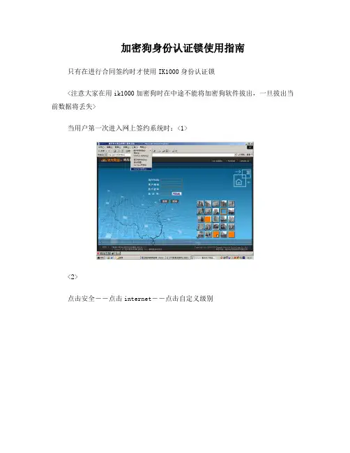
当用户第一次进入网上签约系统时:<1>
<2>
点击安全――点击internet――点击自定义级别
<3>
启用所有AvtiveX控件和插件-点击确定
<4>
点击左下角的<这里>下载驱动程序
把ikall压缩包解压出来
1. 先点击
安装驱动
2. 然后点击
安装好客户端.安装好后会在电脑右下角生成一个
图标
点击右键可以打开.
点用户工具可以更改自己能记住的PIN码.初始PIN码值为:12345678
在用户pin码框里输入pin码点击回车键就自己把用户编码输出来然后输入密码就可以登陆进行签约了.。

CodeMeter WUPI Samples说明For C++WUPI Samples For C++说明文档1.C++的例子当安装完后已经安装在您的电脑上,首先打开CodeMeter Start Center, 选择Samples可进入目录\Software Protection\C++\WupiCalculatorIndex下查找到。
2.该例子的加密原理是由外壳工具AXPROTECTOR和WUPI函数功能组成,用户除了可以用自动外壳工具保护程序外,还可以对源程序的函数段进行自定义加密,并且可以通过WUPI函数来控制该函数段在内存中什么时候解密运行,什么时候再次加密保护起来。
3.首先我们打开外壳配置文件,如果您是CodeMeter用户请打开该目录下WupiCalculator-CodeMeter.WibuAxProject文件,如果您是WibuKey则打开WupiCalculator-WibuKey.WibuAxProject文件,以下我们以CodeMeter为例。
4.双击该外壳配置文件后,外壳程序AxProtector也会被自动启动,如下图:首先要选择需要加密的应用程序exe或者dll,然后下一步如下图:该步骤和后面一些步骤的说明都可以参考外壳的操作说明,这里不一一介绍说明了,一直下一步到Advanced options选项,通常单纯的自动外壳加密的时候”Activate IxProtector/WUPI” 默认是不激活的,而这里我们需要让外壳和我们的WUPI函数功能组合在一起使用时,必须打上勾激活。
接着我们就可以进入下一步进行细节的配置。
该例子是一个计算器例子,并且对计算器里的计算功能进行模块许可分配,如下图,在许可列表里为每个不同的模块功能分配不同的许可,(这些都针对希望对程序中多个功能进行分开授权管理而设定的,否则的话用户默认即可不用设置)然后在下一步里如下图,用户可以把希望做加密的函数名称添加到以下列表中按添加函数按钮会出现如下图,在Name中填入函数名称(该函数名称必须和程序中一致,否则外壳程序会无法查找到该函数),还可以通过Length来设定加密字节多少,而在license list 里如果需要对该函数功能进行模块分授权管理,即可选择上一步已经设定的许可列表里的许可,则会自动绑定到该函数。

一、加密狗使用说明
加密狗支持的操作系统:Windows XP\Windows 7(32位),浏览器推荐使用IE8或者IE9,设置步骤如下;
1、从网站首页下载加密狗驱动,安装,然后重启计算机;
2、把加密狗插在电脑usb口上;
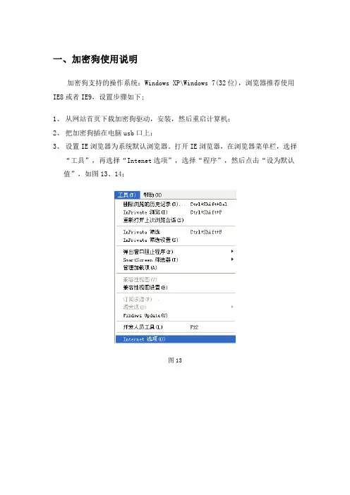
3、设置IE浏览器为系统默认浏览器。
打开IE浏览器,在浏览器菜单栏,选择
“工具”,再选择“Intenet选项”,选择“程序”,然后点击“设为默认值”,如图13、14;
图13
图14
4、打开IE浏览器属性窗口,选择“安全”选项,再选择“自定义级别”,把
包含“ActiveX”控件和插件全部启用,如图15、16;
图15
图16
5、打开IE浏览器,点击菜单栏“工具”,选择“兼容性视图设置”,点击添
加按钮中把系统网站地址添加进去,如图17、18
图17
图18
如这样还不能登录系统,关闭防火墙并卸载除IE浏览器外的其他浏览器,只保留IE浏览器。
如果还不能登录系统,建议更换其他电脑或者重新安装您电脑的操作系统,并重新按上面步
骤操作。

Levante Sistemas deAutomatización y Control S.L.CatálogosLSA Control S.L. - Bosch Rexroth Sales PartnerRonda Narciso Monturiol y Estarriol, 7-9Edificio TecnoParQ Planta 1ª Derecha, Oficina 14(Parque Tecnológico de Paterna)46980 Paterna (Valencia)Telf. (+34) 960 62 43 01*************************VisualMotion GPS 6.0DOK-VISMOT-VM*-06VRS**-FKB1-AE-P • 07/98Reference Manual 280585VisualMotion GPS 6.0Reference Manual DOK-VISMOT-VM*-06VRS**-FKB1-AE-P • 07/98IAE 74792, Rev. G This document is intended to be a reference manual for the CLC Multi-AxesCoordinated Motion Control Card. This manual contains the informationneeded to program the card using VisualMotion32 and covers the followingitems.• I/O Systems• Parameters• Icon/Text Programming• Direct ASCII Communication• DDE Client Interfaces RevisionDate Remarks IAE 74792, Rev A10/91Initial Release IAE 74792, Rev B06/94Updates IAE 74792, Rev C10/94Updates - Not released IAE 74792, Rev D12/94GPS 1.2IAE 74792, Rev E9/95GPS 02IAE 74792, Rev F10/96GPS 05IAE 74792, Rev G 07/98VisualMotion32 - GPS 06© INDRAMAT, 1998Copying this document, and giving it to others and the use or communicationof the contents thereof without express authority, are forbidden. Offenders areliable for the payment of damages. All rights are reserved in the event of thegrant of a patent or the registration of a utility model or design (DIN 34-1).All rights are reserved with respect to the content of this documentation andthe availability of the product.INDRAMAT • 5150 Prairie Stone Parkway • Hoffman Estates, IL 60616Telephone 847-645-3600 • Fax 847-645-6201TechDoc Dept. (LS/HK)TitleKind of documentationDocu-typeInternal file referencePurpose of this document Revision history Copyright Validity Published byVisualMotion GPS 6.0DOK-VISMOT-VM*-06VRS**-FKB1-AE-P Contents IContents1Introduction 1-11.1Purpose of Manual...........................................................................................................................1-11.2Manual Overview..............................................................................................................................1-61.3Overview of CLC..............................................................................................................................1-7CLC System Architecture.................................................................................................................1-7Indramat’s VisualMotion ® Programming Interface..........................................................................1-8CLC BTC06......................................................................................................................................1-8CLC Operating System ....................................................................................................................1-91.4CLC Motion Capabilities.................................................................................................................1-10Non-Coordinated Motion................................................................................................................1-10Coordinated Motion........................................................................................................................1-10Electronic Line Shaft (ELS)............................................................................................................1-112CLC Input/Output Systems 2-12.1I/O Overview.....................................................................................................................................2-12.2Remote I/O Systems........................................................................................................................2-22.3I/O Mapper .......................................................................................................................................2-3I/O Mapper Ladder Logic Format.....................................................................................................2-4I/O Mapper Boolean Format.............................................................................................................2-4I/O Mapper Operators ......................................................................................................................2-5I/O Mapper Considerations ..............................................................................................................2-52.4I/O Bit Forcing ..................................................................................................................................2-62.5Reading and Writing Physical I/O.....................................................................................................2-62.6CLC Registers..................................................................................................................................2-7Register 1: System Control ..............................................................................................................2-8Registers 2-5: Task Control ...........................................................................................................2-10CLC Cycle Control Considerations.................................................................................................2-13Register 6: System Diagnostic Code..............................................................................................2-14Registers 7-10: Task Jog Control...................................................................................................2-14Registers 11-18, 209-240: Axis Control.........................................................................................2-17Register 21: System Status............................................................................................................2-18Registers 22-25: Task Status.........................................................................................................2-19Registers 27 and 28: Eagle Module Inputs/Outputs (CLC-V Only)................................................2-20Register 29: ELS Master Control Register.....................................................................................2-21Register 30: ELS Master Status Register.......................................................................................2-22Registers 31-38, 309-340: Axis Status...........................................................................................2-23VisualMotion GPS 6.0Registers 40-87: DEA (4/5/6) I/O...................................................................................................2-26Registers 88,89: Task A Extend Event Control..............................................................................2-26Registers 90 and 91: Latch and Unlatch........................................................................................2-27Registers 92-94: Mask Pendant Key Functionality.........................................................................2-27Registers 95-97: BTC06 Teach Pendant Status Registers............................................................2-28Registers 98, 99: Teach Pendant Control - Task A-B, C-D............................................................2-29Register 400-405, 410-415: DEA (28/29/30) I/O Registers............................................................2-30CLC Reserved Register Tables......................................................................................................2-313Parameters3-13.1Overview...........................................................................................................................................3-13.2Parameter Transfer Commands......................................................................................................3-23.3List of Parameters............................................................................................................................3-33.4System Parameters........................................................................................................................3-14System Setup (0001-0031)............................................................................................................3-14Jogging and Display (0042-0056)...................................................................................................3-24Program Management (0090-0099)...............................................................................................3-26System Status (0100-0126)............................................................................................................3-29Electronic Line Shaft Parameters 1 of 2 (0150-0170)....................................................................3-33VME Bus (0200-0287)....................................................................................................................3-37BTC06 Teach Pendant (0801-0991)..............................................................................................3-44Electronic Line Shaft Parameters 2 of 2 (1000-1568)....................................................................3-53System Parameter Lists (2000-3108).............................................................................................3-593.5Task Parameters............................................................................................................................3-74Task Setup (0001-0002).................................................................................................................3-74Coordinated Motion (0005-0026)...................................................................................................3-76Robotics (0035-0059).....................................................................................................................3-80Coordinated Motion Status (0100-0113)........................................................................................3-81Task Status (0120-0200)................................................................................................................3-83Task Parameter Lists (2000-2001).................................................................................................3-873.6Axis Parameters.............................................................................................................................3-88Axis Setup (0001-0038)..................................................................................................................3-88Axis Status (0100-0145)...............................................................................................................3-103Electronic Line Shaft (0150-0164)................................................................................................3-106Axis Feedback Capture (Registration 0170-0174).......................................................................3-110Optional SERCOS Data (0180-0196)...........................................................................................3-111Axis Parameter Lists (2000-2001)................................................................................................3-1133.7Drive Parameters.........................................................................................................................3-113Drive Status..................................................................................................................................3-115Required DDS Setup....................................................................................................................3-115 II Contents DOK-VISMOT-VM*-06VRS**-FKB1-AE-PVisualMotion GPS 6.0DOK-VISMOT-VM*-06VRS**-FKB1-AE-P Contents III4VisualMotion Menu Commands 4-14.1Introduction.......................................................................................................................................4-14.2The File Menu ..................................................................................................................................4-2Program Management......................................................................................................................4-2Archive..............................................................................................................................................4-4Transfer Cams .................................................................................................................................4-5Transfer Events................................................................................................................................4-6Transfer I/O Mapper.........................................................................................................................4-6Transfer Parameters........................................................................................................................4-6Transfer Points.................................................................................................................................4-7Transfer Variables............................................................................................................................4-8Transfer Zones.................................................................................................................................4-8Print..................................................................................................................................................4-84.3The Edit Menu................................................................................................................................4-10Clear Current Task.........................................................................................................................4-10Find, Find Next...............................................................................................................................4-10Add Subroutine...............................................................................................................................4-11Add Event Function........................................................................................................................4-11Labels - User Labels ......................................................................................................................4-11Labels - Register Labels.................................................................................................................4-13Labels - Bit Labels..........................................................................................................................4-13Import User Label File....................................................................................................................4-14Export User Label File....................................................................................................................4-144.4The View Menu...............................................................................................................................4-15Subroutines....................................................................................................................................4-15Event Functions..............................................................................................................................4-15Zoom Out .......................................................................................................................................4-154.5The Setup Menu.............................................................................................................................4-16Card Selection................................................................................................................................4-16Configuration..................................................................................................................................4-16Drives.............................................................................................................................................4-17Drives Help Directories...................................................................................................................4-17Coordinated Motion........................................................................................................................4-18I/O Setup........................................................................................................................................4-19Overview.........................................................................................................................................4-21Pendant Security............................................................................................................................4-22CLC Serial Ports.............................................................................................................................4-23VME Configure...............................................................................................................................4-234.6The Tools Menu.............................................................................................................................4-25Breakpoint Control..........................................................................................................................4-25CAM Builder...................................................................................................................................4-25Jogging...........................................................................................................................................4-30VisualMotion GPS 6.0Oscilloscope...................................................................................................................................4-33VisualMotion32, CLC_DDE Release6............................................................................................4-33Show Program Flow.......................................................................................................................4-334.7The Data Menu...............................................................................................................................4-35CAM Indexer..................................................................................................................................4-35Events.............................................................................................................................................4-35Field Bus Mapper (CLC-D Only).....................................................................................................4-37I/O Mapper.....................................................................................................................................4-40PID Control Loops..........................................................................................................................4-44PLS.................................................................................................................................................4-49Points..............................................................................................................................................4-57Registers........................................................................................................................................4-59Registration (Not Functional for GPS 6.0)......................................................................................4-62Sequencer......................................................................................................................................4-63Variables.........................................................................................................................................4-66Zones.............................................................................................................................................4-674.8The Status Menu............................................................................................................................4-68Diagnostic Log................................................................................................................................4-68Drives.............................................................................................................................................4-68Drives on Ring................................................................................................................................4-68System............................................................................................................................................4-69Tasks..............................................................................................................................................4-694.9The Options Menu..........................................................................................................................4-714.10Help................................................................................................................................................4-725Programming Concepts5-15.1Overview...........................................................................................................................................5-15.2Program Tasks.................................................................................................................................5-1Command Execution........................................................................................................................5-15.3Events...............................................................................................................................................5-2Time-based Events..........................................................................................................................5-2Distance-based Events....................................................................................................................5-3Repeating Axis Position (Rotary) Events..........................................................................................5-5Interrupt Input Events.......................................................................................................................5-6Extended External I/O Events..........................................................................................................5-7VME Events......................................................................................................................................5-7Feedback Capture (Probe)...............................................................................................................5-9Event Tables..................................................................................................................................5-105.4Subroutines....................................................................................................................................5-10Function Arguments and Local Variables.......................................................................................5-105.5Sequencer......................................................................................................................................5-11Single Stepping a Sequencer Step.................................................................................................5-12 IV Contents DOK-VISMOT-VM*-06VRS**-FKB1-AE-PVisualMotion GPS 6.0DOK-VISMOT-VM*-06VRS**-FKB1-AE-P Contents VSingle Stepping a Step Function....................................................................................................5-125.6Data and Expressions....................................................................................................................5-13Integers and Floats.........................................................................................................................5-13Constants and Variables................................................................................................................5-13Expressions....................................................................................................................................5-15Mathematical and Logical Operators..............................................................................................5-165.7Tables.............................................................................................................................................5-17Event Table....................................................................................................................................5-19CLC Path Planner...........................................................................................................................5-20Absolute Point Table......................................................................................................................5-22Relative Point Table.......................................................................................................................5-23Zone Protection Table....................................................................................................................5-246Icon Programming 6-16.1Introduction.......................................................................................................................................6-1Working with VisualMotion’s Icon Palettes and Buttons ..................................................................6-1Connecting Icons..............................................................................................................................6-3Icon Labels and Comments .............................................................................................................6-5User Defined Labels.........................................................................................................................6-56.2CLC Icons.........................................................................................................................................6-6Single Axis Icon Palette....................................................................................................................6-6Coordinated Motion Icon Palette......................................................................................................6-7ELS Icon Palette...............................................................................................................................6-8Utility Icon Palette.............................................................................................................................6-9Accel...............................................................................................................................................6-10Axis.................................................................................................................................................6-11AxisEvt............................................................................................................................................6-16Branch............................................................................................................................................6-17Calc................................................................................................................................................6-19Cam................................................................................................................................................6-22CamAdj...........................................................................................................................................6-23CamBuild........................................................................................................................................6-24Cam Indexer...................................................................................................................................6-26Circle..............................................................................................................................................6-30Decel..............................................................................................................................................6-32ELS.................................................................................................................................................6-33ELSAdj............................................................................................................................................6-36ELSMode........................................................................................................................................6-37Event..............................................................................................................................................6-38Finish..............................................................................................................................................6-39Go...................................................................................................................................................6-40Home..............................................................................................................................................6-41I/O...................................................................................................................................................6-42。
Synway IPPBX SeriesUC200Synway Information Engineering Co., LtdContentContent (i)Copyright Declaration .......................................................................... i i Chapter 1Product Introduction (1)1.1Characteristic Features (1)1.2Hardware Description (1)Appendix A Technical Specifications (3)Appendix B Technical/sales Support (4)Copyright DeclarationAll rights reserved; no part of this document may be reproduced or transmitted in any form or by any means, electronic or mechanical, without prior written permission from Synway Information Engineering Co., Ltd (hereinafter referred to as ‘Synway’).Synway reserves all rights to modify this document without prior notice. Please contact Synway for the latest version of this document before placing an order.Synway has made every effort to ensure the accuracy of this document but does not guarantee the absence of errors. Moreover, Synway assumes no responsibility in obtaining permission and authorization of any third party patent, copyright or product involved in relation to the use of this document.Chapter 1 Product IntroductionThank you for choosing the Synway IPPBX Series UC200 products (hereinafter referred to as ‘UC200’). It is a powerful, reliable and cost-effective VoIP solution that Synway developed for Enterprise Unified Communications, Customer Service Center, Hotel Voice Communications, etc.1.1 Characteristic Features●UC200-15 supports up to 15 concurrent calls and up to 60 extensions.●UC200-30 supports up to 30 concurrent calls and up to 120 extensions.●UC200-45 supports up to 45 concurrent calls and up to 220 extensions.●UC200-60 supports up to 60 concurrent calls and up to 330 extensions.●Integrates 4 FXO ports and 2 FXS ports for communications without power.●Built in with multi-level IVR systems, supporting teleconferencing, call queuing, CDR,sound monitoring, call broadcasting, etc.●Supports HTTPS, TLS and SRTP to guarantee the safety of communications.●Includes two 100-megabyte network interface cards, supporting three modes: Dual,Bridge and Route.●Has 8G internal storage with extendable external storage via TF and USB cards.1.2 Hardware DescriptionUC200 adopts an external 12V power supply. The table below gives a detailed introduction to the interfaces, buttons and LEDs on UC200.For other hardware parameters, refer to Appendix A Technical Specifications.Appendix A Technical SpecificationsDimensions186×30×108mm3Weight0.83 kgEnvironmentOperating temperature: 0℃—45℃Storage temperature: -20℃—85℃Humidity: 8%— 90% non-condensingStorage humidity: 8%— 90% non-condensing LANAmount: 2 (10/100 BASE-TX (RJ-45))Self-adaptive bandwidth supportedAuto MDI/MDIX supportedFXS PortAmount: 2Type: RJ11Maximum transmission distance: 1500mFXO PortAmount: 4Type: RJ11ImpedanceTelephone line impedance: Compliant with thenational standard impedance for three-component network Console PortAmount: 1 (MiniUSB)Baud rate: 115200bpsConnector: MiniUSB ConnectorData bits: 8 bitsStop bit: 1 bitParity unsupportedFlow control unsupportedNote: Follow the above settings to configure the serial port; or it may work abnormally.Power RequirementsInput power: 12V DC not less than 3A Signaling & ProtocolSIP signalingSupported protocol: SIP V1.0/2.0, RFC3261 Audio Encoding & DecodingG.711A 64 kbpsG.711U 64 kbpsG.729 8 kbpsSampling Rate8kHzAppendix B Technical/sales Support Thank you for choosing Synway. Please contact us should you have any inquiry regarding our products. We shall do our best to help you.HeadquartersSynway Information Engineering Co., Ltd/9F, Synway D&R Center, No.3756, Nanhuan Road, Binjiang District,Hangzhou, P.R.China, 310053Tel: +86-571-88860561Fax: +86-571-88850923Wechat QR Code: Scan the QR code below to add us on Wechat.Technical SupportTel: +86-571-88864579Mobile: +86-189********Email: ***********************Email: **********************MSN: **************************Sales DepartmentTel: +86-571-88860561Tel: +86-571-88864579Fax: +86-571-88850923Email:****************。

VingCard说明书目录VingCard门锁简介-------------------------------------------------2需要重点关注的操作事项----------------------------------------3各部门日常注意事项----------------------------------------------4门锁工程卡更换方法----------------------------------------------6常见的不可开启门锁的原因:----------------------------------6 门锁故障分析及处置----------------------------------------------7客人卡发卡-----------------------------------------------------------8后备卡Fail-Safe Card制作--------------------------------------10员工卡制卡----------------------------------------------------------11操作密码管理-------------------------------------------------------16常见的LockLink开锁记录说明--------------------------------19 LockLink掌上电脑综述------------------------------------------21LockLink的操作---------------------------------------------------23封房卡的制作-------------------------------------------------------27记录查询的方法----------------------------------------------------31Vision服务器端程序的安装-------------------------------------34数据库备份方法----------------------------------------------------34恢复数据库的方法-------------------------------------------------40License输入方法---------------------------------------------------42Vision客户端程序的安装----------------------------------------43VingCard门锁简介门锁按使用卡片可分为磁卡锁、磁卡+IC卡锁、感应卡锁三种。

WibuKey加密流程快速指南加密流程安装WibuKey软件开发包之后,在开始“所有程序“中找到“AxProtector”,请点击进入该程序,AxProtector为WibuKey加密产品中的“自动加密软件”。
首选我们先来加密一个应用程序比如windows自带的计算器(C:\WINDOWS\system32\calc.exe)来测试下加密的效果,你同样也可以使用你自己的软件作为测试。
我们选择外壳自动加密工具AxProtector,选择并打开进入会让你选择windows下32位应用程序或者64位应用程序或者.NET程序或者Mac操作系统上的应用程序或者JAR的JAVA包(请注意不同类型程序必须对应其加密程序类型)。
这里我们选择32位的应用程序作为测试,然后进入以下画面开始加密:选择想要加密的EXE或者DLL文件,这里我们选择加密计算器calc.exe,并且自动生成加密后的exe在原文件的同目录下的protected目录下,如果您的是动态库DLL,那么就选择DLL类型的。
然后下一步:默认选择是CodeMeter,而您使用的是另一款产品Wibukey RU+或者U+的话请取消Use CodeMeter,而点选Use Wibukey,其中Firm Code每个开发商正式购买以后都会分配到一个唯一的号码,而User Code可由开发商自定义数值来定义不同的软件产品或者模块。
Firm Code 和User Code组成了一组许可信息,也就是说用该信息加密了你的软件,而加密锁上也必须要有相应的许可,也就是相同的一组Firm Code和Product Code才能运行使用该软件。
如果您使用U+测试时Firm Code请用测试码10,并选择对应算法4,而如您用RU+测试时Firm Code用测试码250010,并选择对应算法5。
产品码为客户自定义号码,Product Code假设设定为17,其他都默认然后下一步。
Verizon Internet Security Suite Multi-Device Powered by McAfeeInstallation Guide for Multi Devices for Residential UsersContentsIntroduction 3System requirements 4Installing Verizon Internet Security Suite Multi-Device 6 Downloading your software 6 Sign in to Security Dashboard 6Choose your device 7Download your software on this computer 7Download your software on another computer 8Download your software on a smartphone 8Download your software on a tablet 8 Troubleshooting your installation 10IntroductionNow that you’ve installed Verizon Internet Security Suite Multi-DevicePowered by McAfee software on your computer, you should protectyour other devices. This guide helps you download and install VerizonInternet Security Suite Multi-Device Powered by McAfee on anothercomputer, tablet or smartphone.Verizon Internet Security Suite Multi-Device software for your computeris a proactive, always-updating, security bundle that helps protect youridentity and your computer from viruses, spyware, email and IM scams,and hackers and online predators.You can also install Verizon Internet Security Suite Multi-Device softwareon your tablet or smartphone. Then, you can lock and locate your deviceif it’s lost. And if you think it’s s tolen, you can even wipe its data toprotect your private information.Your product subscription allows you to install SafeKey passwordmanager on all your devices. SafeKey securely stores your usernamesand passwords for your favorite sites, and logs in for you—with just oneclick.System requirementsYour devices must meet these minimum system requirements to runVerizon Internet Security Suite Multi-Device Powered by McAfee.Windows computers▪IBM-compatible personal computer, 1 GHz processor or higher▪One of these Windows operating systems:- Microsoft Windows XP (32-bit) with Service Pack 3 (SP3) or later- Windows Vista (32 or 64-bit) with Service Pack 1 (SP1) or later- Windows 7 (32 or 64-bit) with Service Pack 1 (SP1) or later- Windows 8 (32 or 64 bit)- Windows 8.1 (32 or 64 bit)▪500 MB hard disk space▪512 MB RAM for Windows XP, or 2 GB RAM for all other Windowsoperating systems▪1024 x 768 resolution or higher▪Microsoft Internet Explorer 7.0 or later, or Mozilla Firefox 4.0 orlater, or Google Chrome 10.0 or later▪Internet connectionMac computers▪Apple Macintosh computer with Intel Core processor (werecommend a Core 2 Duo processor)▪Mac OS X 10.7 (Lion), or 10.8 (Mountain Lion), or 10.9 (Mavericks)▪300 MB hard disk space▪ 2 GB RAM▪1024 x 768 resolution or higher▪Mozilla Firefox 12 or later, or Apple Safari 5.0 or later (required forSiteAdvisor browser plug-in)▪Internet connectionSmartphones▪Google Android 2.3 and 4.0 ▪iOS 5 or laterTablets▪Google Android 2.3 and 4.0 ▪iOS 5 or laterInstalling Verizon Internet Security Suite Multi-DeviceYou can install your Verizon Internet Security Suite Multi-DevicePowered by McAfee software on another computer, tablet orsmartphone in a few simple steps. Before you begin, make sure that yourdevice meets the minimum system requirements and is connected to theInternet.Downloading your softwareYou can download your Verizon Internet Security Suite Multi-DevicePowered by McAfee software when you sign in to your Verizon account.From the Security Dashboard you can download your software onanother computer, tablet or smartphone, monitor and manage thesecurity status of all your devices, and lock, locate or wipe data on yoursmartphone or tablet.Sign in to Security Dashboard1 Go to the Verizon website () and sign in to MyVerizon.2 From the left menu, select My Services, and then select InternetSecurity Suite.3 In the Broadband Essentials & Extras Management pane, clickManage.4 Click Security Dashboard.Choose your device1 On your Security Dashboard, click the + tab.2 Select the device you want to protect.Download your software on this computer1 To protect this computer, click Download.2 Choose your software, and then click Download.3 Accept the McAfee License Agreement, and then click Download.Download your software on another computer1 To protect another computer, click Send Link.2 Choose your software, and then click Next.3 Enter your email, and click Send.Download your software on a smartphone1 To protect a smartphone, click Send Link.2 Select the smartphone you want to protect.3 Choose your software, and then click Next.4 Enter your country and phone number.5 Choose if you want to receive the download link in a text or an email.If you choose email, enter your email.6 Click Send Text or Send Email.Download your software on a tablet1 To protect a tablet, click Send Link.2 Select the tablet you want to protect.3 Choose your software, and then click Next.4 Enter your country and nickname your tablet.5 Enter your email.6 Click Send Email.Troubleshooting your installationHere are the most common problems that you might encounter duringyour software installation, and solutions to fix them.▪If your device does not meet the minimum system requirements,upgrade your device.▪If you’re cannot download your software, make sure your device isconnected to the Internet, and then try again.▪If your software installation cannot continue, contact VerizonSupport ().▪If your software order is denied, you might live in a country that wedon't export to in accordance with the United States law. If so, youwill not be able to activate and use this software properly. For moreinformation, please contact Verizon Support().。
WIDI JACKOWNER’S MANUAL V07Please read this manual completely before using this product. The pictures in the manual are for illustration purposes only. They may differ from the actual product. For more technical support content and videos, please visit the .IMPORTANT INFORMATION⚫WARNINGImproper connection may cause damage to the device.⚫COPYRIGHTCopyright © 2021 CME Pte. Ltd. All rights reserved. CME is a registered trademark of CME Pte. Ltd. in Singapore and/or other countries. All other registered trademarks are the property of their respective owners.⚫LIMITED WARRANTYCME provides a one-year standard Limited Warranty for this product only to the person or entity that originally purchased this product from an authorized dealer or distributor of CME. The warranty period starts on the date of purchase of this product. CME warrants the included hardware against defects in workmanship and materials during the warranty period. CME does not warrant against normal wear and tear, nor damage caused by accident or abuses of the purchased product. CME is not responsible for any damage or data loss caused by improper operation of the equipment. You are required to provide aproof of purchase as a condition of receiving warranty service. Your proof of purchase is the delivery or sales receipt, showing the date of purchase of this product. To obtain service, call or visit the authorized dealer or distributor of CME where you purchased this product. CME will fulfil the warranty obligations according to local consumer laws.⚫SAFETY INFORMATIONAlways follow the basic precautions listed below to avoid the possibility of serious injury or even death from electrical shock, damages, fire, or other hazards. These precautions include, but are not limited to, the following:-Do not connect the instrument during a thunder.-Do not set up the cord or outlet to a humid place, unless the outlet is specially designed for humid places.-Always follow the instructions carefully when setting up the instrument.-Do not expose the instrument to rain or moisture, to avoid fire and/or electrical shock.-This product contains magnets. Please do not place this product close to devices that are susceptible to magnetic interference, such as creditcards, medical equipment, computer hard drives, etc.-Keep the instrument away from electrical interface sources, such as fluorescent light and electrical motors.-Keep the instrument away from dust, heat, and vibration.-Do not expose the instrument to sunlight.-Do not place heavy objects on the instrument; do not place containers with liquid on the instrument.-Do not touch the connectors with wet handsCONNECTIONWIDI Jack is a wireless Bluetooth MIDI interface. It adds Bluetooth MIDI (transmitting and receiving) to MIDI devices with different MIDI connectors, such as: synthesizers, MIDI controllers, MIDI interfaces, keytars, electric wind instruments, v-accordions, electronic drums, electric pianos, electronic portable keyboards, audio interfaces, digital mixers, etc. At the same time, WIDI Jack can also connect devices and computers with a built-in BLE MIDI feature, such as: standard Bluetooth MIDI controllers, iPhones, iPads, Mac computers, Android mobile phones, PC computers, etc.The WIDI Jack interface has two 2.5mm mini TRS MIDI sockets and a USB-C power supply socket (no data function), as well as an on/off switch and a slide switch:The mini TRS socket marked with at the bottom of the interface is to be connected to the MIDI OUT of MIDI device through anoptional accessory cable. This to obtain power supply and receiveMIDI information from the device. Next it will be converted intoBluetooth MIDI messages and sent to other devices.♦The mini TRS socket marked with at the bottom of the interface is to be connected to the MIDI IN of MIDI device through an optional accessory cable. Next it will send the received Bluetooth messages to the connected MIDI device.♦The socket marked with USB-C connects a standard 5 volts USB power source (for example: charger, power bank, computer USBsocket, etc.). Therewith it supplies power to the WIDI Jack. This isonly necessary if the MIDI OUT socket of the MIDI device does notsupply power or when the WIDI Jack is only connected to MIDI INwhere MIDI power is not available.♦The push switch on the right side of the interface is used for the following quick operations (please confirm that the product firmware has been upgraded to the latest version). The following operationsare based on firmware v0100 or higher:-When the WIDI Jack is NOT powered on, press and hold the button. Power on the WIDI Jack until the green LED lightflashes slowly for 3 times. Then release the button. Theinterface will manually reset to the factory default.-When the WIDI Jack is powered on, press and hold the button for 3 seconds and then release it. The interface will bemanually set to “force peripheral” mode. If the WIDI Jack wasconnected to other BLE MIDI devices, this connection will beterminated by following this procedure.♦♦The slide switch on the back of the WIDI Jack can be used to switch the input polarity of the mini TRS jack to adapt to the two differentTRS MIDI cable specifications. Namely Type-A or Type-B (theoptional TRS cable from CME is Type-B). With this switch featureWIDI Jack can be applied to most TRS MIDI specifications in themarket.Note 1: To determine whether your MIDI device is Type-A or Type-B, please check the manual of your MIDI device or consult the manufacturer.Note 2: If you find that MIDI messages CANNOT be sent or received between the WIDI Jack and the connected MIDI device, try changing this switch to a mode that matches the polarity of the TRS MIDI cable.♦There is a magnet inside the back of the WIDI jack, which can be easily attached to the device with the magnet patch accessory.⚫WIDI Jack Cable Options⚫WIDI Jack LED indicatorVideo instruction: https://youtu.be/BvPyvlnH9sA♦When the power is supplied normally, the LED light will be lit.♦Blue LED flashes slowly: the device starts normally and waits for connection.♦Blue LED light stays on constantly: the device has beensuccessfully connected.♦Blue LED flashes quickly: the device is connected and is receiving or sending MIDI messages.♦Light blue (turquoise) LED: as in the central mode, the device has been connected to other peripheral devices.♦Green LED: The device is in firmware upgrader mode. Please use the iOS or Android WIDI App to upgrade the firmware (Please findthe App download link on ).⚫Add WIDI Jack Bluetooth MIDI function for standard MIDI devices Video instruction: https://youtu.be/MN4myXp544A1.Plug the2.5mm mini TRS Jack of the WIDI Jack optional cable intothe mini TRS Jack socket of the interface box.2.Plug the other end of the WIDI Jack optional cable into the MIDIOUT and MIDI IN sockets of the MIDI device.Note 1: The above picture shows the connection of the 5-pin DIN MIDI socket, and the connection method for other MIDI socket specifications is similar.Note 2: If the MIDI device only has a MIDI OUT socket, there is no need toconnect the other cable.Note 3: If the MIDI OUT socket of the MIDI device cannot provide 3.3v~5vpower supply, or you want to connect only the MIDI IN of the device, pleaseuse a general USB Type-C cable to connect to a standard 5v USB powersupply.⚫Connect two WIDI JacksVideo instruction: https://youtu.be/4QQlZ_J8GOY1.Turn the power on of both MIDI devices equipped with WIDI Jack.2.The two WIDI Jacks will be connected automatically, and the blueLED will change from slow flashing to constant light (when MIDIdata is transmitting, the LED will flash accordingly).⚫Connect WIDI Jack with Bluetooth MIDI deviceVideo instruction: https://youtu.be/4SdHf6MmAhs1.Turn on both the MIDI devices plugged with WIDI Jack as well asthe Bluetooth MIDI devices.2.WIDI Jack will automatically connect with the built-in Bluetooth MIDImodule of the MIDI device, and the blue LED will change from slowflashing to constant light (when MIDI data is transmitting, the LEDwill flash accordingly).Note: If WIDI Jack cannot automatically pair with another Bluetooth MIDIdevice, it may be caused by a compatibility issue. Please contact CME through for technical support.⚫Connect WIDI Jack with macOS XVideo instruction: https://youtu.be/EieinyhPvjs2.Click the [Apple icon] on the upper left corner of the screen, clickthe [System Preferences] menu, click the [Bluetooth icon], andclick [Turn Bluetooth On], then exit the Bluetooth settings window.3.Click the [Go] menu at the top of the screen, click [Utilities], andclick [Audio MIDI Setup]Note: If you don't see the MIDI Studio window, click the [Window] menu at the top of the screen and click [Show MIDI Studio].4.Click the [Bluetooth icon] at the upper right of the MIDI studiowindow, find the WIDI Jack that appears under the device name list,and click [Connect]. The WIDI Jack’s Bluetooth icon will appear inthe MIDI studio window, indicating the successful connection.Please note, the MIDI studio can now be minimized to run in thebackground. If no music software is running, macOS willautomatically disconnect the Bluetooth MIDI connection after aperiod to optimize resource usage. That is why it is recommendedto keep MIDI studio running and minimize the view of the window. ⚫Connect WIDI Jack with iOS deviceVideo instruction: https://youtu.be/wfxU_X8H5lc1.Go to the Apple AppStore to search and download the freeapplication [midimittr].Note: If the App you are using already has a Bluetooth MIDI connectionfunction, please directly connect to the WIDI Jack on the MIDI setting page in the App.3.Click the [Settings] icon to open the settings page, click [Bluetooth]to enter the Bluetooth setting page, and slide the Bluetooth switchto turn on the Bluetooth functionality.4.Open the midimittr App, click the [Device] menu at the bottom rightof the screen, find the WIDI Jack that appears under the list, click[Not Connected], and click [Pair] on the Bluetooth pairing requestpop-up window, the status of WIDI Jack in the list will be updated to[Connected], indicating that the connection is successful. Then youcan press the Home button of the iOS device to minimize midimittrand keep it running in the background.5.Open the music app that can accept external MIDI input, and selectWIDI Jack as the MIDI input device on the settings page, you canstart using it.⚫Connect WIDI Jack with Windows 10First, the Windows version of music software must integrate Microsoft's latest UWP API to use the Bluetooth class compliant MIDI driver that comes with Windows 10. Most music software has not yet integrated this API for various reasons. As far as we know, only Cakewalk by Bandlab currently integrates this API, so it can directly connect to WIDI Jack or other standard Bluetooth MIDI devices.Of course, there are some alternative solutions for MIDI transmission between the Windows 10 Bluetooth MIDI driver and music software through virtual MIDI port driver, such as Korg BLE MIDI driver. Starting from the firmware version v0.1.3.7, WIDI is fully compatible with the Korg BLE MIDI Windows 10 driver. It can support multiple WIDIs connected to Windows 10computers at the same time with two-way MIDI data transmission. The operations are as follows:Video instruction: https://youtu.be/JyJTulS-g4o1.Please visit Korg official website to download the BLE MIDIWindows driver.https:///us/support/download/driver/0/530/2886/2.After decompressing the driver files with the decompressionsoftware, click the exe file to install the driver (you can checkwhether the installation is successful in the sound, video, and gamecontroller list of the device manager).3.Please use the WIDI App to upgrade the firmware of the WIDIdevice to v0.1.3.7 or later (for upgrade steps, please refer to therelevant instructions and videos on ). At thesame time, please set the upgraded WIDI BLE role to "ForcedPeripheral" to avoid automatic connection when multiple WIDIs areused at the same time. If necessary, you can rename each WIDIafter the upgrade, so that you can distinguish between differentWIDI devices when you use them at the same time.4.Please make sure that the Windows 10 and the Bluetooth driver ofyour computer has been upgraded to the latest version (thecomputer needs to be equipped with Bluetooth 4.0/5.0 capability).5.Plug a WIDI into the MIDI device, turn on the power to start theWIDI. Click "Start" - "Settings" - "Devices", open the "Bluetooth andother devices" window, turn on the Bluetooth switch, and click "AddBluetooth or other devices".6.After entering the Add Device window, click "Bluetooth", click theWIDI device name listed in the device list, and then click "Connect".7.If you see "Your device is ready to go", please click "Done" to closethe window (after connecting, you can see WIDI in the Bluetooth listof the device manager).8.Please follow steps 5 to 7 to connect other WIDI devices toWindows 10.9.Open the music software, in the MIDI settings window, you shouldbe able to see the WIDI device name appearing in the list (Korg BLEMIDI driver will automatically detect the WIDI Bluetooth connectionand associate it with the music software). Just select the desiredWIDI as the MIDI input and output device.In addition, we have developed WIDI UHOST as a professional hardware solution for Windows users, that meets the requirements of professional users for ultra-low latency and long-distance control to the greatest extent. Please visit /widi-uhost for details.⚫Connect WIDI Jack with Android deviceLike the case of Windows, the Android Music App must integrate the universal Bluetooth MIDI driver of Android’s OS to communicate with the Bluetooth MIDI device directly. Most music apps haven't integrated this functionality for various reasons. Therefore, you need to use specific apps dedicated to connecting Bluetooth MIDI devices as a bridge.Video instruction: https://youtu.be/PYwtlg4cN2k1.Go to the PlayStore to search and download the free application[MIDI BLE Connect].2.Turn on the power of the MIDI device with the WIDI Jack plugged in,and confirm that the blue LED flashes slowly.3.Turn on the Bluetooth function of the Android device.4.Open the MIDI BLE Connect App, click [Bluetooth Scan], find theWIDI Jack that appears in the list, and click [WIDI Jack], it will showthat the connection is created successfully. At the same time, theAndroid system will send a Bluetooth pairing request notification.Please click on the notification and accept the pairing request. Afterthis you can press the Home button on the Android device tominimize the MIDI BLE Connect App and keep it running in thebackground.5.Open the music app that accepts an external MIDI input, and selectWIDI Jack as the MIDI input device on the settings page, then youcan start using it.⚫Group connection with multiple WIDI devicesWIDI Jack supports group connection from firmware version v0100 and higher. Group connections will allow two-way data transmission of 1-to-4 MIDI Thru and 4-to-1 MIDI merge. And it supports simultaneous use of multiple groups.Video instruction: https://youtu.be/ButmNRj8Xls1.Go to the iOS Appstore to search for and download the freeapplication WIDI App.(Version 1.2.19 or higher)2.Upgrade WIDI Jack to the latest firmware. Then keep only one WIDIJack powered on.Note: Please remember to avoid having multiple WIDI Jacks powered on at the same time. Otherwise, they will be automatically paired one to one. This will cause the WIDI App to fail in finding the WIDI Jack you want to connect to as they are already occupied.3.Set your WIDI Jack as “force peripheral” role and rename it.Note 1: After the BLE role is set as “force peripheral”, the setting will be automatically saved in the WIDI Jack.Note 2: Click the WIDI Jack device name to be renamed. The new name will be effective once restarted.4.Repeat the above steps to set all WIDI Jacks to be added to thegroup.5.After all WIDI Jacks are set to the “force peripheral” role, they can bepowered on at the same time.6.Click the "Group" menu, and then click "Create New Group".7.Enter the name of the group.8.Drag and drop the WIDI Jack to the central and peripheral positions.9.Click "Download Group". The setting will be saved in all WIDI Jacks.From here on, these WIDI Jacks will be restarted and automaticallyconnect as the same group by default.Note 1: Even if you power off the WIDI Jack, all the group setting status will still be remembered. When you power them on again, they will be automatically connected in the same group.Note 2: If you want to forget the group connection settings, please use the WIDI App to connect to the WIDI Jack with "Central" role and click "ResetDefault Connections". Again, only power on this central device to allow thepairing with WIDI App. If you power on multiple group devices they willautomatically connect as a group. This will make it impossible for the WIDI App to make to connection as they will already be occupied.SPECIFICATIONSpecifications are subject to change without notice.FAQ⚫The LED of the main adapter of WIDI Jack is not lit.-Is the main adapter connected to the MIDI OUT jack of the MIDI device? -Has the MIDI device been turned on?-When using a USB power supply, please check whether the USB power is turned on or whether the USB power bank has sufficient power (pleasechoose a power bank with Low Power charging mode for smartwatches, Bluetooth headphones such as AirPods, and fitness trackers).⚫WIDI Jack cannot receive or send MIDI messages.-Try sliding the switch on the back of the WIDI Jack to adjust it to the TRS MIDI mode that matches the polarity of the selected cable.⚫When I only use MIDI IN, can I only connect the optional cable of the WIDI Jack to the MIDI IN socket of the device?-Yes. But it needs to be connected to an external USB (5v) power supply or power bank.⚫Can WIDI Jack connect wirelessly with other BLE MIDI devices?-If the BLE MIDI device complies with the standard BLE MIDI specification, it can be connected automatically. If the WIDI Jack cannot automaticallyconnect, it may be a compatibility issue. Please contact CME for technical support through .⚫The connection between WIDI Jack to iOS or macOS is unstable or with noticeable latency.-In most cases this issue occurs after updating the firmware of your WIDI device, or after upgrading your operating system. This can cause conflicts between the previous Bluetooth connection cache and the upgradedversion. To solve this, open the Bluetooth settings page of your iOS ormacOS device, forget or remove the previous WIDI pairing and restartBluetooth. Now establish a new connection with your WIDI device.⚫The wireless connection distance is very short, or the latency is large, or the signal is intermittent.-WIDI Jack uses the Bluetooth standard for wireless transmission. When the signal is strongly interfered or obstructed, the transmission distance and response time will be affected by objects in the environment, such as trees, reinforced concrete walls, or environments with moreelectromagnetic waves.CONTACTEmail:****************Website: 。
威谱数字电话交换系统威谱通讯商务平台TDMx2000系列技术手册广州市华谱电子科技有限公司目录1.系统概述 (1)1.1.系统简介 (1)1.2.优势功能 (1)1.3.技术规格 (2)1.3.1.容量配置 (2)1.3.2.电源要求 (3)1.3.3.环境要求 (3)1.3.4.E、F型机传输距离 (3)1.3.5.B、P型机传输距离 (3)1.3.6.H型机传输距离 (3)1.3.7.外形尺寸 (3)1.3.8.重量 (3)1.3.9.系统拓扑结构 (4)1.4.结构与安装 (4)1.4.1.机柜前视图 (4)1.4.2.机柜结构 (5)1.4.3.机柜间连接 (7)1.4.4.安装前的准备 (8)1.4.5.主机安装 (9)2.常用功能码操作说明 (12)3.数据简易配置(仅限于B、P、H型机) (14)3.1.自动装机 (14)3.2.恢复出厂IP地址 (15)4.系统管理平台 (15)4.1.管理软件登录 (15)4.2.库下载 (16)4.3.端口维护 (16)4.4.功能表维护 (16)4.5.路由表维护 (17)4.6.服务等级维护 (17)4.7.前缀码表维护 (17)4.8.主机设置 (18)4.9.库上传 (20)4.10.语音导航配置 (20)4.11.重启 (21)4.12.保存库 (21)4.13.打开库 (21)4.14.导出库 (21)4.15.导入库 (22)4.16.上传音乐 (22)4.17.编程实例 (23)4.17.1.分机号码设定 (23)4.17.2.分机服务等级设定 (23)4.17.3.内线使用模式 (23)4.17.4.呼叫转移、呼叫等待设定 (24)4.17.5.数字话机设定 (24)4.17.6.同组代接设定 (24)4.17.7.工作组设定 (24)4.17.8.通话时间限制设定 (25)4.17.9.群功能保护设定 (25)4.17.10.通话音量调节 (25)4.17.11.PC话务台权限设定 (26)4.17.12.限制码设定 (26)4.17.13.外线呼入模式 (27)4.17.14.不同线路呼入不同语音功能 (28)4.17.15.内置电脑话务员的应用 (28)4.17.16.电脑话务员语音的录制 (29)4.17.17.PRI数字中继设定 (32)4.17.18.数字中继呼入模式 (33)4.17.19.PRI数字中继汇接 (33)4.17.20.PRI混合通道模式 (36)4.17.21.一号信令的设置方法 (36)4.17.22.VPN (37)4.17.23.出局号及IP加发的设定 (38)4.17.24.默认出局号修改 (39)4.17.25.计费设定 (39)4.17.26.IVR语音导航设定 (39)4.17.27.数字录音系统设定 (40)4.17.28.公共寻线组设定 (41)4.17.29.呼入加拨前缀设定 (41)4.17.30.自动外转外呼叫功能 (42)4.17.31.随身密码 (42)4.17.32.强插、强拆、监听功能 (42)4.17.33.分机局向限制 (43)4.17.34.分机来电显示限制 (43)4.17.35.话机修改服务等级 (43)4.17.36.电话修改网管号码 (43)4.17.37.模拟中继直接转移 (43)4.17.38.缩位拨号 (44)4.17.39.路由允许码设置 (44)4.17.40.语音叫醒功能 (45)4.17.41.内外线振铃区分 (45)4.17.42.拨0出局 (45)4.17.43.直出中继 (45)4.17.44.智能路由设置 (46)4.17.45.内外线直拨 (46)4.17.46.GSM、CDMA无线中继卡设定 (47)4.17.47.电脑话务员外转外白名单功能 (49)4.17.48.经理秘书功能 (50)4.17.49.服务等级跳转功能 (51)4.17.50.号码分析功能 (51)4.17.51.黑名单功能 (52)5.电脑命令行编程 (52)5.1.电脑连接 (52)5.1.1.通过串口连接 (52)5.2.登录 (53)5.2.1.通过超级终端串口登录 (53)5.2.2.通过超级终端TCP/IP登录 (53)5.3.输入规则 (54)5.4.自动装机 (55)5.5.显示网络配置信息 (55)5.6.配置网络 (56)5.7.更改口令 (56)5.8.配置呼叫控制参数 (56)5.9.系统日期/时间参数配置 (57)5.10.系统计费开关 (57)5.11.功能码维护 (58)5.12.读取设备序列号 (59)5.13.激活设备 (59)5.14.重启系统 (59)5.15.退出系统 (59)6.系统升级 (59)6.1.下载 (59)6.2.升级 (59)6.3.注意事项 (59)6.4.主控板 (61)6.5.扩展主控板 (62)6.6.二次电源板 (62)6.7.模拟用户板 (63)6.8.环路中继板 (64)6.9.数字用户板(二代) (65)6.10.信令板 (66)6.11.数字中继板(E1) (66)7.机器常见故障 (67)7.1.常见程序故障的排除 (67)。
第一分册CXT路测软件篇第1章测试工具的准备工作1) 测试用笔记本要求:内存1G以上,硬盘120G以上,CPU 2.0Ghz以上,操作系统为WINDOWS XP SP3/WINDOWS VISTA/WINDOWS7。
软件当中不要有冲突的杀毒软件,最好在测试前就关闭所有杀毒软件2) 测试设备:路测型测试终端;GPS-支持NMEA接口GPS(推荐使用环天BU-353)。
第2章CXT软件安装2.1 CXT LTE软件安装CXT软件仅仅数据采集,软件将前台现场的反映情况正确的反馈出来。
当连接了测试设备,软件将记录测试日志后,软件便处于数据采集状态;此时不能进行日志回放等分析操作。
用户可根据中兴公司提供的光盘当中CXT.exe安装程序,按照默认步骤安装即可。
若用户想指定的安装程序,只需要手动选择即可。
安装完我们的软件之后我们要进行激活端口http://192.168.0.1/goform/goform_process?goformId=MODE_SWITCH&switchCmd=DEBU G&is_persist=0,DEBUG成功之后,安装中兴公司提供的软件驱动程序,依据软件特性,选择我的电脑——管理——管理器——更新驱动程序。
(DEBUG的过程当中要注意,因有些浏览器本身就为一个BUG,那么在浏览器当中进行端口激活,可能成功率很低,我们需要做的就是在普通的打开文件当中进行激活,例如我的电脑的标题栏等)此时,打开软件就可以查看我们的版本信息,如下图2.2 GPS驱动安装1、采用CXT LTE配置的环天(BU353)GPS,安装GPS驱动:测试笔记本电脑是采用XP 系统则安装XP驱动,如果是WIN7系统则安装压缩包里面提供的VISTA驱动即可。
2、采用其他GPS,则安装GPS提供的驱动,如果默认接口不是NMEA则需要设置为NMEA2.3 CXT软件加密狗CXT软件加密狗无需安装驱动,即插即用。
CmAct中文指导手册
软件加密流程
首先可通过安装好我们的开发包的安装程序后运行AxProtector来自动加密开发商的程序。
1.运行AxProtector
选择加密的程序的类型,32 64位应用程序,或者.Net程序等
进入后选择需要加密的源程序
选择需要加密的exe执行程序或者dll动态库。
下一步选择User CodeMeterAct
并输入Firm Code和Product Code, 作为测试我们使用firm code为5010,product code为13,
注意后面许可发放激活中的firm code和product code必须和这里对应才能相互关联起来。
其他都可以默认,然后下一步。
选择本地模式还是网络模式。
本地模式只有本地才可以正常使用该许可。
网络模式可以只让一台机器安装许可文件,而其他机器可以通过网络来访问该许可。
并且可以在license options里选择网络模式时候的,网络访问人数的计算方式,如进程计算或者IP计算。
一直连续下一步到该画面选择左边是加密强度,右边是侦测各种类型的破解工具列表
然后下一步定义出错信息框
一直以下一步直到最后finish完成加密工具。
接着可以到原文件的目录下找到protected目录下的加密后的程序文件。
覆盖掉原来的程序
后运行会发现出现以下出错框
没有相应的5010:13这组许可,所以不能打开正常使用。
必须由开发商发放激活许可才能正常使用。
开发商软保护许可发放激活流程
1.开发商发放许可信息文件
首先开发商会发送许可信息文件给最终的使用用户。
该文件里饱含着开发商需要绑定的许可信息和用户的硬件信息。
许可信息文件的生成可以通过以下命令行:
CmBoxPgm /f5010 /p13 /ca /lif:"TemplateTestFirst.wbb" /lpn:"FirstTest" /lpid:0001 /lfs:Non
/los:win
其中/f5010 /p13代表着firm code5010和product code 13. 也就是需要绑定的许可信息号码。
/lif:"TemplateTestFirst.wbb"是生成的文件名称。
/lpn:"FirstTest"为该许可在最终用户的CodeMeter控制中心里显示的名字。
/los:win为绑定相应的操作系统
/lfs:Non为定义需要绑定最终用户的硬件信息
Non:不绑定任何硬件
B:1:绑定BIOS
C:1:绑定CPU
D:1:绑定硬盘
N:1:绑定网卡
同样也能组合这些硬件信息如需要绑定所有以上硬件信息为:bcdn:4
如果只是绑定部分硬件如硬盘和CPU可定义为cd:2,依次类推。
字母后面的数字如bcdn:4其中的4代表着以上4个硬件必须全部符合才算正确许可,只要
有一个硬件不正确,该许可就立刻实效而无法使用。
如果写成bcdn:3其中的3代表只要满
足前面4个硬件中的任意3个硬件,该许可就有效。
注:软加密的许可是默认情况下是不允许在虚拟机中激活的,因为虚拟机的特殊机制造成了可以通过复制自身的镜像系统来达到复制多套加密软件的目的。
不过CMACT系统里仍然提供了可以开启在虚拟机中运行的参数,只要在上述命令行中加入/lopt:vm就可以使该许可运行在虚拟机中,但请注意如果您这么做,您的软件就可能被反复复制到任意机器上运行了。
2.最终用户申请许可认证文件
最终用户拿到该许可信息文件,并且导入到CodeMeter控制中心
导入方法1:
打开CodeMeter控制中心,文件->导入license->选择从开发商那里获得的许可信息文件导入方法2:
可直接把许可信息文件拖入到CodeMeter控制中心中。
导入后会出现如下画面:
最终用户点选激活能生成许可申请文件,该文件中就包含着先前开发商发送给最终用户的许可信息文件中的需要绑定的硬件信息。
并且把生成的许可申请文件通过email等形式发还给开发商。
许可申请文件的生成方法:
点选激活或者激活license按钮后出现以下画面
按下一步
选择创建许可请求再按下一步
选择许可申请文件的存放路径,并且按提交。
生成文件后完成。
接着把该生成的许可申请文件发送给开发商即可。
3.开发商授权许可文件
当开发商获得最终用户那里发来的许可申请文件后,使用命令行
CmBoxPgm /f5010 /p13 /pup:30 /ca
/laf:"32767-3239898881.WibuCmRaC","Activation.WibuCmRaU" /lpn:"My first license"
/lpid:0001 /lfs:Non /los:win
/f5010 /p13 对应于前面的许可信息号码
/pup:30 使用期限设定为30天(还有其他激活时间,计数器等参数可查看CodeMeter开发手册的命令行)
/laf:"32767-3239898881.WibuCmRaC","Activation.WibuCmRaU”中的"32767-3239898881.WibuCmRaC"为最终用户发来的许可申请文件,"Activation.WibuCmRaU"为新生成的许可更新文件名称
/lfs:Non 对应于之前需要绑定的用户硬件信息
/los:win 对应于之前的操作系统
执行生成许可升级文件,并且发送还回最终用户升级。
4.最终用户激活许可
最终用户收到开发商授权的许可升级文件,拖入到CodeMeter控制中心进行激活,激活后如下
现在最终用户已经获得了该许可权限而可以正常使用开发商加密后的软件了。
Contact Us (联系我们):
地址:上海市杨浦区锦创路20号1602室(200433)
中文网站:/cn
电话:86-21-55661790/1/2/3 传真:86-21-55661780
邮箱:info@。