伊顿电气Digirrip3000继电保护装置使用说明书中文版
- 格式:pdf
- 大小:1.24 MB
- 文档页数:66

DT3000Microprocessor-based feeder, transformer backup protective relayThere’s a certain energy at Eaton. It’s the power of uniting some of the world’s most respected names to build a brand you can trust to meet your every power management need. The energy created supports our commitment to powering business worldwide. From power distribution to power quality and control, Eaton allows you to proactively manage your complete power system by providing electrical solutions that make your applications more reliable, efficient and safe. Visit /electrical.All of the above are trademarks of Eaton Corporation or its affiliates. Eaton has a license to use the Westinghouse name in Asia Pacific. ©2010 Eaton Corporation.505150G51GCB 52DT3000Load2DT3000 Microprocessor-based feeder, transformer backup protective relay Aug-2011DT3000 Microprocessor-based feeder, transformer backup protective relayKey featuresDescriptionFunction overviewProtection functionEaton’s DT 3000 is a microprocessor-based overcurrent protective relay, with integrated functions of protection, measurement and control. With INCOM interface, DT 3000 can realize data sharing and remote control with remote upstream host computer. Its protection feature generally provides phase components and ground components with: inverse time overcurrent protection, short delay time protection, and instantaneous overcurrent protection, overload alarming, regional interlocking. Complete self-inspection function ensures the device to provide reliable protection for primary equipments. Thismicroprocessor-based protection relay can display intuitively graphic operating characteristic curve types on the panel, with dual-window indication of fault information. Besides, it has a special indicator light for indication in case of remote tripping control. With DIP dial switch configuration on the back panel of the device, an even superior protection solution can be offered as well.Testing functionThis mode can be used in regular inspection of relay’s protective function (can select tripping or no-tripping). But when its single phase or ground current is inspected to be 0.1 times higher than primary rating current of CT, the device will automatically set back to testing mode with indication of “ERR” information.Other special functionsAutomatic reset function: additional automatic reset function can be provided for protective operating signals (condition is when the current falls below 0.5*In)Programmable protection output relay: same output relay can allocate different protection function outputs.Withdrawable structure: when relay basic device is withdrawn from its housing frame, the device will automatically be short connected to CT circuit and automatically switch off I/O and power supply circuit, ensuring safety of personnel and equipments.Each protection function is independent from each other. They can meet requirements for all kinds of systems, when used in combination with other functions.Regional interlocking functionCan quickly remove regional protection of inverse time and short delay time as a response, replacing expensive busbar differential protection Communication functionDT3000 provides function for communication with PowerNet system, monitoring remotely the operation status of primary equipments. Real-time operation parameters can be viewed on the panel and transmitted to PowerNet via INCOM interface:Real-time operating information inquiryGive remote command for switching circuit breakers Reset relay devices after closing Download protection set pointsInverse time overcurrent protection Short delay time overcurrent protection Instantaneous overcurrent protection Overload alarming and node output Tripping protection for discriminatorRegional interlocking protection for hierarchy switchesSingle phase current Ground currentMaximum ground and phase currents since the last reset Current level and phase position causing tripping Tripping causesCurrent transformer ratioSetup values for each current setup options Software versionStatus of circuit breakersRemote control functionBased on PowerNet protocol, INCOM interface allows remote monitoring system to control operations for local primary equipments, including:I 4t ItFLAT I 2t3Dual power supply: when normal power supply voltage for the device falls down to 75% of voltage rating, the device will start CT circuit for power supply. Even in the case of normal power supply faults, theprotection function can still work, providing reliable protection constantly for operating equipments.Introduction of protection functionDT 3000 provides 11 types of protection characteristic curves for primary equipment in medium voltage power distribution system, as shown below.DT3000 Microprocessor-based feeder, transformer backup protective relay Key featureCharacteristic curve diagram of DT 3000 overcurrent protective relay’s phase components and ground componentsExplanation :In the characteristic curves of ANSI and IEC ,the unit for horizontal axis is Ipu (CT primary operate value),while in short delay time and instantaneous curves, the horizontal axis unit is In(primary current value when CT secondary current at 5A).In the case of thermal tripping curve, horizontal axis units are In for all the threecircumstances, which shall be distinguished in coordination and programming.Inverse time overcurrent protectionInverse time overcurrent protection is set up , including curve types, operate values, set up of inverse-time time-factor. Operate value setup item sets up current level when inverse time current tripping function begins timing. If after the pre-setup time, overcurrent conditions still exist, then tripping relay of the device will operate.The picture on the right shows how the inverse time overcurrentThe above is a typical short delay operate-value setup. The dashed line section is shown when users select different operate-values; thesame short delay time setup is the dashed line combination vertical to time axis, as shown belowShort delay time overcurrent protectionShort delay time overcurrent protection is responding to short circuit condition faults. The set-up items include current operate value setup and delay setup. The former is the current level of the overcurrentwhen this protection begins timing. The latter is the time size from the beginning of timing till operating tripping.operate value passes operate value set-up and make horizontal movement along time-current coordinate system.① Curve refernce standard: ANSI C37.112② Curve refernce standard :IEC 255-3current Thermal trip curveZ SI f52The circuit breaker charged负荷DT3000With DSPSac power supplyLoadDT-3000带DSPSV 0≌CurrentANSI curve ①Current IEC curve ②InstantaneousFixed extreme Severe Exteme InstantaneousCurve graphicCurve graphic SevereShort delayShort delayc u r r e n t时间Dashed range composed by short delay operate valuesCurrentt i m ec u r r e n tI nc u r r e n tRated current muliplesInverse timeMinimum operate valueDT3000 Microprocessor-based feeder, transformer backup protective relay Aug-2011505150G 51G4DT3000 Microprocessor-based feeder, transformer backup protective relayKey featuresCurrentCurrent3 phase overcurrent protection3 phase quick-break ground overcurrent protection Ground overcurrent protection Regional interlockingPhase component regional interlocking terminal: TB1-13,14,Ground component regional interlocking terminal: TB1-11,12,When this function is not used, they should be short connected separately.Protection function list and respective ANS I standard codest i m eDashed range composed by short delay operate valuesInstantaneous fixed valueOverload alarmingWhen load current reaches 85% of phase component inverse time overcurrent operate-value, overload function starts timing, with “High load” LED flicking in red. If the current is below 85%, the timer will reset. Only when the current reaches 85% again, the timer will restart. When there are 3 times of timer overtime::1、”High Load”LED on relay’s panel keeps in red.2、Alarming signal transmitting to the whole communication network3、If DIP-5 is in “0N” position, closed terminals TB2-4 and TB2-5conduct overload signal node output. When the current is below 85%, the relay returns.Regional interlocking functionWhen subordinate protection device sends out tripping signal, it will generate a 175ms-delay regional interlocking signal to superiorprotection device. Before the superior protection device responds to the fault, the subordinate protection device clears faults during this period. When the signal ends, if the current does not fall down below the fixed value, then the superior protection device will operate immediately for tripping.Please be noted that in the case of coordination of short delay and inverse time curves, the minimum tripping time of inverse time shall not be lower than short delay time operate-value, otherwise it will cause protection chaos.Instantaneous overcurrent protectionInstantaneous operating protection reacts to big fault current condition with two cycles as responding time to faults. When instantaneous protection is set as “NONE”, the device provides discriminatorprotection function. That is, if and only if during the first 10 cycles after closing the circuit breaker, if the load current exceeds 11*In, the discriminator export will operate instantaneously. If it’s more than 10 cycles, then it will operate when next time the circuit breaker closes from its opening position.Ground fault protectionGround fault protection has below three protection set-up :1、Inverse time overcurrent curve, operate-value, time setup ;2、Short delay overcurrent protection operating value and time setup ;3、Instantaneous operating protection operate-value. Ground curve shape is independent from phase component curve shape.In addition, below are other differences between them: in thermal curves, when the inverse time overcurrent time factor to ground is 1*In;n, time factor to phase is 3*In;When ground instantaneous protection is set as “NONE”, ground instantaneous protection will be shielded completely, without providing discriminator distinction protection.DT3000 Microprocessor-based feeder, transformer backup protective relay Aug-20115DT3000 Microprocessor-based feeder, transformer backup protective relay T echnical dataTechnical dataTesting standardsCertification :Current inputCUL /UL ,recognized (file# E154882)CAN /CSAC22.2 14.M91UL 1053(6#,1999 version) ANSI C37.90(1989)EN 61010-1(1993)-limited to DT303* EN 55011(1991)Radiation testsEN 55011(1991) Class A, Type 1FCC47 CFR~ Chapter 1, Part15, Class A Immunity testANSI C37.90.1 (1989) surge capacity 2.5kV OSWC 4kV FTSWCANSI C37.90.1 (1995)-RFRadiation capacity 35V /M- all modes EN61000-4-2(1995)-ESD immunity 8kV IEC255-22-2(1989)-ESD immunity 8kVEN61000-4-3(1995) frequency radiation immunity 10V/m IEC255-22-3(1989) frequency radiation immunity1 0V/m EN61000-4-3(1995) fast transient 10V/m IEC255-22-4(1995) fast transient 10V/mEN61000-4-5(1995) surge immunity2/1kV C/DMEN61000-4-6(1995) frequency carrying immunity 10Vo EN61000-4-11(1994) voltage dip\ fluctuation\ intermittent interferenceInsulation strengthCurrent input end: 3000V 1m, phase to phase Seismic testIn accordance with UCB requirements and California lawOutput tripping node(Tripping OC /Comm ,Trip Inst&CommColse) Instantaneous 30A ac /dc 0.25 second Breaking 0.25A 250Vdc Breaking 5A 120/240Vac Continous 5A@ 120/240VacReference ANSI C37.90 Chapter 6.7Control power supplyCT secondary rating CT loadSaturation value28*InInstantaneous value Ct thermal parameter5A<0.04 Ohm<0.1VA @ rated current (5A)30 *In(Chicago version) 100*In 1second 10A continuous 500A 1secondRatingOperating ValueConsumption power48V-250Vdc 120-240Vac 24V-48Vdc28V-280Vdc 66-264Vac 19V-56VdcDT3000DT3030DT3000 (DC)48V 125V 250V 120V 240V 10VA 10VA 10VA 10VA 10VADT3100(DC)48V 125V 250V 120V 240V 10VA 10VA 10VA 10VA 10VADT3030 10VA MaximumPhase components and ground components time current curveThermal modeANSIANSI C37.112 1996IECIEC255-31989(moderate inverse time)(very inverse time) (extreme inverse time) (fixed time)(moderate inverse time)(very inverse time)(extreme inverse time)(moderate inverse time)(very inverse time)(extreme inverse time)(fixed time)It I2t I4t FLATIEC-A IEC-B IEC-C IEC-DDT3000 Microprocessor-based feeder, transformer backup protective relay Aug-2011DT3000 Microprocessor-based feeder, transformer backup protective relayT echnical dataCT ratio (primary)set range:Phase & ground components10/25/50/75/100/150/200/250/300/400/500/600/630/800/1000/1200/1250/1500/1600/20002400/2500/3000/3200/4000/5000Phase & ground components (Chicago version)5/10/25/50/75/100/150/200/250/300/400/500/600/630/800/1000/1200/1250/1500/1600/2000/2400/2500/3000/3200/4000/5000Time precision:Counter delay overcurrent time ±10% 1.5IpuShort delay time±50msTime delay setCounter delay overcurrent time factor:IT 12T 14T Curve:0.2~40148 alternative values]IT 12T 14T Curve:0.2~40[48 alternative values]( Chicago version)Fixed time:0.2-2.0[2 1 alternative values]ANSI(all):0.1-5.0[50 alternative values]IEC(all):0.025-1.0[40 alternative values]IEC(all):0.05-1.0[20 alternative values]( Chicago version)Short delay:O.05-1.5[22 alternative values]Auxiliary relayContinuous 5A@120/240Vac5A@30Vdc5A continuous (Chicago version)Communication function:Compatible to PowerNet/via INCOMBaud rate:1200bps or 9600bpsAddress:INCOM setting up from the front panelNote 1: When the device sets overcurrent value of phase components, there is no “NONE“ option. That is, “NONO” option canbe applicable for all protection functions. Charge can at least provide inverse time overcurrent protection;Phase component overcurrent operate-value set rangeInverse time overcurrent set * Note:1(0.2-2.2)*In[29 alternative values](0.2-1.0)*In[16 alternative values](Chicago version)Short delay set(1-1 1*)In,None[25 alternative values]Instantaneous value set * Note:2(1-25)*In,None[30 alternative values]Ground component overcurrent set reference rangeInverse time overcurrent set(0.1N2.0)*In[26 alternative values]Short delay set(0.1-11)*In,None[45 alternative values]Instantaneous value set(1-25)*In,None[33 alternative values]Environment factorExternal environment:indoors only,Pulltion index:ⅡAltitude:2500m mounting type:ⅡEquipment position:close to main switch ASAPOperating temperature:-30℃-+55℃Operating humidity:0-95% relative humidity (no condensing)Storage temperature:-40℃-+70℃Regional selectivity interlocking:Phase: inverse time overcurrent and short delayGround: inverse time overcurrent and short delayCurrent monitoring:RMS 3 phase and groundDisplay precision: ±1% full scale (0.04In-In)±2% full scale(In-2In) demand current: average sampling rate for 5 secondsOverload: 85% inverse time overcurrent fixed valueNote 2:when setting the instantaneous value of phase component as “NONE”, the device provides below functions: if and only if thecircuit breaker is at the first 10 cycles in closing position from opening position, if the device detects the current over 11*In, it will trip immediately. Otherwise, only when the circuit breaker switches from opening to closing position next time, this function will work.DT3000 Microprocessor-based feeder, transformer backup protective relay Aug-20116DT3000 Microprocessor-based feeder, transformer backup protective relay Mounting and wiringMounting and wiringDT 3000 device front panel introduction1:two display windows provided on device front panel: one is “RMS demand”. This window is used for displaying detected analogue quantity and operating current value for protection operation. The other window is “Setting/Test Time/Trip cause” for displaying current menu items in Setting/Test Time mode, or fault information during operation.2:11 buttons on the device front panel for selective paring due to different function requirements. Different colors and characters show each function.3:The device provides 14 indication LEDs in total, including the communication indicator light on the rear panel of the device for respective function indication, or status indication. And the LED in the curve graph is designed as two-color tube, red or green, indicating current fault type or contents of setting items.Terminals on DT 3000’s rear panelTB1J1: retainJ2: retainJ3: retain J4:GNDJ5: supply input1J6: supply input2J7: retainJ8: retainJ9: circuit breaker status inputJ10: circuit breaker status inputJ11: ground-regional interlocking outputJ12: ground-regional interlocking inputJ13: phase-regional interlocking outputJ14: phase-regional interlocking inputJ15: regional interlocking terminal TB2J1: communication terminal1J2: communication terminal2J3: communication groundJ4:closing export/overload alarmingJ5:closing export/overload alarmingJ6: trip alarming ring common terminalJ7: trip alarming ring normally open terminalJ8 trip alarming ring normally close terminalJ9: device fault common terminalJ10: device fault normally open terminalJ11: device fault normally close terminalJ12: phase/ground instantaneous fault trip exportJ13: or ground fault trip exportJ14: inverse time of phase ground/ short delay/ remote tripping exportJ15: or protection exports for any types of phase components Current input terminal(5A rated)A1:A phase current incomingB1:B phase current incomingC1:C phase current incomingG1:Zero sequence current incomingA2:A phase current outcomingB2:B phase current outcomingC2:C phase current outcomingG2:Zero sequence current outcomingNote:1:TBl-15 regional interlocking signal common terminalshall not be connected to ground;2:TBl-9, 10 terminals will generate voltage after the device is energized. The voltage is used to detect circuit breaker’s status input;3:TB2-12,13、TB2-14,15 TB2-4,5 are all export relay nodes.7DT3000 Microprocessor-based feeder, transformer backup protective relay Aug-2011DT3000 Microprocessor-based feeder, transformer backup protective relayWiring diagramC1B1A1C2B2A2G1G2C2C1B2B1A2A1G2G1ØCØB ØA Digitrip 300052A BCCTABCOther Devices111213141556910452bTB1Close CKTCS CTB24TB25CS TTB214TB215TB212TB21352a 52a••TB2123456789101112131415Typical wiring diagramAC/DC supply inputCommunication Instantaneous Overcurrent When zerosequence CT is not mounted, pls see the left diagram:CT residual current wiring diagramZerosequence CTGrond zone Interlock Phase zone InterlockZone CommonOut In Out InNote :1. Communication shield shall not be connected to ground or any electrical circuits ;2. Protection export nodes can refer to DIP switch setup3. When regional interlocking function is used, please remove short connection to regional interlocking terminal.8Communication interface Remote closingTripping alarm ringProtection function offInstantaneous export Overcurrent / inverse timeRemote trip exportDT3000 Microprocessor-based feeder, transformer backup protective relay Aug-2011136.7238.3119.164.3128.556.7113.0169.7226.11.5R AD4••68.35.5170.767.89.912.77.415.726.747.595.09.485.3130.0118.1133.437.6260.4236.5Fixed ,5A ,48.250Vdc ;120/240 Vac Withdrawable ,5A ,48—250Vdc ;120/240 Vac Fixed ,dual-power supply PS 120 Vac ,5A Fixed ,dual-power supply PS 240 Vac ,5A Fixed ,24/48 Vdc ,5A ,CE mark Withdrawable ,24/48 Vdc ,5AFixed ,5A ,48-250Vdc ;120/240 Vac(Chicago code version) Basic unit with sensitive ground protectionDT-3000DT-3001DT-3010DT-3020DT-3030DT-3031DT-3100DT-3200DT3000 Microprocessor-based feeder, transformer backup protective relay DimensionDimensional drawing (mm)cutout size (mm)DIA 10 cutoutOrdering informationDimension and mounting Size9DT3000 Microprocessor-based feeder, transformer backup protective relay Aug-2011© 2011 Eaton CorporationAll Rights ReservedPrinted in ChinaDT3000-CN (11-2011)Eaton CorporationAsia Pacific HeadquarterNo.3, Lane 280, Linhong Road,Changning District,Shanghai 200335Tel :86-21-52000099Fax :86-21-52000200Eaton is dedicated to ensuring that reliable, efficient and safe power is available when it’s needed most. With unparalleled knowledge of electrical power management across industries, experts at Eaton deliver customized, integrated solutions to solve our customers’ most critical challenges.Our focus is on delivering the right solution for the application. But, decision makers demand more than just innovative products. They turn to Eaton for an unwavering commitment to personal support that makes customer success a top priority. For more information, visit /electrical.Eaton is a registered trademark of Eaton Corporation.All trademarks are property of their respective owners.。

伊顿电力保护解决方案关于伊顿伊顿是一家多元化的动力管理公司,致力于提供高效节能的解决方案,帮助客户更有效的管理电力、液压和机械动力。
伊顿于 2012年 11月收购了库柏工业集团。
2012年伊顿和库柏两家公司的总销售额为 218亿美元。
伊顿在许多工业领域都是全球技术领导者,包括电气产品;电能质量、输配电及控制系统和服务;电力传输、照明和布线产品;工业设备和移动工程机械所需的液压动力元件、系统和服务;商用和军用航空航天所需的燃油、液压和气动系统;以及帮助卡车和汽车提升性能、燃油经济性和安全性的动力及传动系统。
伊顿拥有约 10.3万名员工,产品销往 175多个国家和地区。
自 1993 年进入中国以来,伊顿公司通过并购、合资和独资的形式在中国市场持续稳步增长,旗下所有业务集团——电气、宇航、液压和车辆都已在中国制造产品和提供服务,并把亚太区总部设在上海。
伊顿中国目前拥有 18 个主要的生产制造基地,超过 10000 名员工、 4 个研发中心,年销售额超过 10 亿美元。
我们坚信,如此全面出众的产品组合以及覆盖大众分销、专业电源行业以及 IT 渠道的优秀销售网络,将极大加强伊顿的整体竞争力,进一步巩固和推进伊顿的市场领导地位。
伊顿中国电能质量业务部介绍伊顿公司旗下伊顿电气集团百年来一直致力于电力应用安全,为客户提供包括整体方案前期规划、产品配置和售后服务在内的一站式服务,更有丰富的产品系列涵盖电源品质、输入输出配电、机柜、制冷和机房气流管理、电力监控和管理,为客户提供高效、安全、可靠的整体解决方案。
伊顿电气电能质量业务部提供业界领先的不间断电源( U PS )产品的同时,不断开发适合不同行业的整体解决方案,为客户提供更丰富的产品以及更多附加值的服务,成为深得客户信赖的电能质量管理的合作伙伴,从而实现了从产品技术供应商到电能质量管理整体解决方案供应商的转变,长期拥有中国 UPS 市场份额第一的位置。
在过去的一个世纪里,伊顿电气始终坚持创新,不断丰富产品,精进技术,追求品质,完善服务。
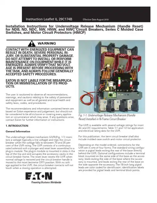
Installation Instructions for Undervoltage Release Mechanism (Handle Reset) for NDB, ND, NDC, NW, HNW, and NWC Circuit Breakers, Series C Molded Case Switches, and Motor Circuit Protectors (HMCP)The user is cautioned to observe all recommendations,warnings, and cautions relating to the safety of personnel and equipment as well as all general and local health and safety laws, codes, and procedures.The recommendations and information contained herein are based on Eaton experience and judgement, but should not be considered to be all-inclusive or covering every applica-tion or circumstance which may arise. If any questions arise, contact Eaton for further information or instructions.1. INTRODUCTION General InformationThe undervoltage release mechanism (UVR)(Fig. 1-1) moni-tors a voltage (typically a line voltage) and trips the circuit breaker when the voltage falls to between 70 and 35 per-cent of the UVR rating. The UVR consists of a continuous rated solenoid with a plunger and reset lever assembled to a plug-in module. The plug-in module is mounted in slots in the top of the trip unit and occupies the accessory cavity in the circuit breaker frame. The reset lever resets the UVR when normal voltage is restored and the circuit breaker handle is moved to the reset (extreme OFF) position. With no volt-age applied to the UVR, the circuit breaker contacts will not touch when a closing operation is attempted.The UVR is available with several voltage ratings for most AC and DC requirements. Table 1-1 and 1-2 list application and electrical rating data for the UVR.For this publication, the term circuit breaker shall also include molded case switch and motor circuit protector. Depending on the model ordered, connections for the UVR are in one of four forms. The standard wiring configu-ration is pigtail leads exiting the rear of the base directly behind the UVR. Optional configurations include a terminal block mounted on the same side of the base as the acces-sory, leads exiting the side of the base where the acces-sory is mounted, and leads exiting Ihe rear of the base on the side opposite the accessory. The 18-inch long pigtail leads are color coded for identificaion: identification labelsare provided for pigtail leads and terminal block points.CONTACT WITH ENERGIZED EQUIPMENT CAN RESULT IN DEATH, SEVERE PERSONAL IN-JURY , OR SUBSTANTIAL PROPERTY DAMAGE. DO NOT ATTEMPT TO INSTALL OR PERFORM MAINTENANCE ON EQUIPMENT WHILE IT IS ENERGIZED. ALWA YS VERIFY THAT NO VOLT -AGE IS PRESENT BEFORE PROCEEDING WITH THE TASK, AND ALWA YS FOLLOW GENERALL Y ACCEPTED SAFETY PROCEDURES.EATON IS NOT LIABLE FOR THE MISAPPLICA-TION OR MISINSTALLATION OF ITS PROD-UCTS.Fig. 1-1. Undervoltage Release Mechanism (Handle Reset) Installed in N-Frame Circuit Breaker2EATON CORPORATION Instruction Leaflet IL 29C174BEffective Date August 2010Fig. 2-1. Undervoltage Release Mechanism (Handle Reset)KitThis instruction leaflet (IL) gives detailed procedures for installing the UVR.2. INSTALLATIONNote: The UVR can be field-installed in ND, HND, and NDC circuit breakers under UL File E64983. The UVR can be field-inslalled in NW, HNW, and NWC circuit breakers.The UVR is listed for factory installation under UL File E7819.For sealed circuit breakers (NDB), Underwriters Labora-tories Inc. UL 489 requires that internal accessories be installed at the factory. The UVR is listed for factory installation under UL File E7819.Where local codes and standards permit and UL listing is not required, internal accessories can be field in-stalled in sealed circuit breakers. In this case, UL listingbecomes invalid and the label should be removed.Before attempting to install the UVR, check that the catalog number is correct as ordered and that the rat-ing of the accessory satisfies job requirements.The UVR, shown in kit form in Fig. 2-1, is installedin the left accessory mounting cavity of a 2-, 3-, or 4-pole circuit breaker. A UVR must be installed in the circuit breaker before the circuit breaker is mounted in an electrical system. To install the UVR, perform the following procedures:BEFORE REMOVING A CIRCUIT BREAKER IN-STALLED IN AN ELECTRICAL SYSTEM, MAKE SURE THE CIRCUIT BREAKER IS SWITCHED TO THE OFF POSITION AND THERE IS NO VOLTAGE PRESENT WHERE WORK IS TO BEPERFORMED. SPECIAL ATTENTION SHOULDBE PAID TO REVERSE FEED APPLICATIONS. THE VOLTAGES IN ENERGIZED EQUIPMENT CAN CAUSE DEATH OR SEVERE PERSONAL INJURY .Note: A circuit breaker that is mounted in an electrical system must be removed to install the accessory. T o ensure correct accessory installation, the circuit break-er must be placed on a horizontal surface.Note: For new circuit breaker installation, trip unit must be installed in circuit breaker before attempting to install a UVR.2-1. Switch circuit breaker to OFF position.Note: Molded case switch trip units are not equipped with a PUSH-TO-TRIP button. For molded case switches, omit step 2-3.2-2. Disconnect and remove circuit breaker from installa-tion and terminal connections.2-3. Press PUSH-TO-TRIP button to trip operating mecha-nism, and check that the handle moves to TRIP position with white colored indicator visible in the breaker cover’s escutcheon window.2-4. Remove circuit breaker cover screws and covers. Note: T o install UVR, circuit breaker operating mecha-nism must be in tripped position and the handle ispushed to “ON” position. (Fig. 2-3)3Instruction Leaflet IL 29C174BEffective April 2010EATON CORPORATION 2-5. Remove interphase barrier between accessory mount-ing cavity and operating mechanism (see Fig. 2-2). 2-6. Rotate 180° and re-install interphase barrier in base (see Fig. 2-2).2-7. Install UVR as described in following steps (see Fig. 2-3): a. Press trip button to trip breaker to “TRIP” posi-tion.b. Push circuit breaker handle towards the ON po-sition and hold while sliding UVR plug-in module into slots in trip unit (Fig.2-3) until retaining clip snaps into trip unit. For terminal block assemblies, slide terminal block into mounting slot on side of base as plug-in module is being positioned.Note: For a UVR having rear or opposite-side exiting pigtail leads, (Fig. 2-4) thread leads through center trough in side of base before attempting to insert the mounting bracket. Pigtail leads exiting in this manner should be eased through trough as mounting bracket is inserted into trip unit retaining slots. Use center trough also for leads exiting the side of the circuit breaker.CAUTIONLEADS SHOULD BE FORMED AND ROUTED TO CLEAR ALL MOVING PARTS WHEN AC-CESSORY IS PROPERL Y INSTALLED. PIGTAIL WIRES COULD BE DAMAGED IF IN CONTACT WITH MOVING PARTS.2-8. Route wiring to meet installation requirements (Fig. 2-4). If required, complete routing of leads to opposite side through rear wiring trough.FAILURE TO KEEP FINGERS AWA Y FROM MOVING PARTS CAN CAUSE PERSONAL INJURY . WHEN CHECKING ACCESSORY , DO NOT PUT FINGERS NEAR MOVING PARTS INSIDE CIRCUIT BREAKER CASE. SPRINGS CAUSE INTERNAL PARTS TO MOVE QUICKL Y AND WITH FORCE.2-9. Perform mechanical check of UVR after installation: a. With the circuit breaker still electrically isolated, reset the circuit breaker.b. Mechanical check. Using a small flat-blade screwdriver, (Fig 2-5), push in and hold solenoid plunger. Switch circuit breaker to ON. Release solenoid plunger and check that circuit breaker trips.c. Reset circuit breaker handle and check that handle arm moves reset lever (Fig. 2-5) to reset the sole-noid plunger.Fig. 2-2. Interphase Barrier Replacement4 EATON CORPORATION Instruction Leaflet IL 29C174BEffective April 20102-12. Where practical and after taking all necessary safety precautions, apply rated voltage to UVR. Reset and close circuit breaker. Confirm that circuit breaker trips when volt-age is removed.2-13. Install circuit breaker.Note: Accessory labels show connection diagram for UVR contacts. Pigtail leads are color coded orange and brown.2-14. Connect UVR as required (see Fig. 2-7). Eaton as-sumes no responsibility for the malfunctioning of accesso-ries installed improperly by the customer.Fig. 2-4. Accessory Wiring OptionsFig. 2-3. UVR Installationd. If mechanical check does not trip circuit breaker,see if UVR and intermediate plunger are correctly installed. If UVR and intermediate plunger appear to be properly installed and problem persists, contact Eaton.WHEN INSTALLING CIRCUIT BREAKER MAIN COVER, MAKE SURE THAT ALL INTERNAL PARTS ARE IN PLACE: • ALL LEADS ARE CLEAR OF THE COVER.2-10. With circuit breaker handle in the TRIPPED position and accessory pigtail leads (if used) routed as required, in-stall circuit breaker covers. Secure with pan-head screws. Torque to 22-24 Ib-in, (2.49- 2.72 N.m).2-11. Place accessory labels (supplied with kit) on circuit breaker (see Fig. 2-6).CAUTION5Instruction Leaflet IL 29C174BEffective April 2010EATON CORPORATION Fig. 2-5. Screwdriver Depressing Undervoltage Release’s Solenoid Plunger Fig. 2-6. Preferred Mounting Locations for Accessory Nameplate LabelsFig. 2-7. Undervoltage Release Mechanism (Handle Reset) Connection Diagram6 EATON CORPORATION Instruction Leaflet IL 29C174BEffective April 2010TABLE 1-1: AC UNDERVOLTAGE RELEASE MECHANISM RATINGS ①Supply Voltage, (V) FrequencyVoltage, (V) Min.Max.Max.VA 0212 50-60 Hz 12 4.28.410.2 1.925153110240324 50-60 Hz 248.416.820.4 2.4520361048482.3560 4.14 1103.411203.84127 4.19 2084.782205.5240 6.48 380 6.84 4158.34409.24 48011① Endurance - 500 electrical operations plus 2500 mechanical operations.② UVR will overide a momentary voltage dip up to the response time shown③ Unlatching occurs 6 milliseconds before circuit breaker contacts begin to separate ④ For 1 minute522381120150015002500524402440521385Approximate Operating Time (ms)Dielectric ④Withstand Voltage, (V)Min.②UVRResponse Initial ③Breaker Contact SeperationMaximum Breaker Contact SeperationCatalog Suffix 0833.640.80548-60 50-60 Hz 21.0Dropout Voltage PickupVoltage 50-60 Hz 168 93.5 110-12750-60 Hz44.5 77.0 Electrical Operating RatingsApplication Ratings266 380-50032311 208-240 50-60 Hz 84 146 177 297Instruction Leaflet IL 29C174BEffective April 2010EATON CORPORATION TABLE 1-2: DC UNDERVOLTAGE RELEASE MECHANISM RATINGS ①Supply Voltage, (B) Voltage, (V) Min.Max.Max.VA 201212 4.28.410.2 2.645203610242124248.416.820.43.6523391048483.6460 5.461102.861203.36125 3.632204.842506.25① Endurance - 500 electrical operations plus 2500 mechanical operations.② UVR will overide a momentary voltage dip up to the response time shown③ Unlatching occurs 6 milliseconds before circuit breaker contacts begin to separate ④ For 1 minutePickup VoltageDropout Voltage 53046521372137Initial ③Breaker Contact SeperationMaximum Breaker Contact Seperation11201500ApplicationRatings 150084145.6176.8 220-2505Approximate Operating Time (ms)Dielectric ④Withstand Voltage, (V)Min.②UVR Response21.0 93.533.640.82826 110-125 44.5 77.0 Electrical Operating Ratings Catalog Suffix 2348-60IL 29C174BEffective August 2010Eaton CorporationElectrical Group1000 Cherrington ParkwayMoon Township, PA 15108United States877-ETN-CARE (877-386-2273)© 2008 Eaton Corporation All Rights Reserved Printed in USA Publication No. 6634C84H03 April 2010PowerChain Management is a registered trademark of Eaton Corporation.All other trademarks are property of theirrespective owners.。

ATA系列自动电源转换装置出众的整体解决方案 ATA—执行机构IZM9系列ATA 系列自动电源转换装置ATA 系列自动电源转换装置ATA 系列概述 ...................................................................................4型号说明 ...............................................................................5主要技术数据及性能指标 .................................................................6控制器 .................................................................................7电气线缆 ..............................................................................16执行断路器IZM9系列型号说明 ..............................................................................17脱扣器技术参数 ........................................................................18系统概览 ..............................................................................19可选附件 ..............................................................................23外形及安装尺寸 ........................................................................24系统电气图 ............................................................................48选型与订货 ............................................................................69订购指南 (73)ATA 系列执行断路器IZM9系列目录3ATA系列自动电源转换装置概述ATA系列产品描述伊顿的ATA系列自动转换开关装置,满足额定电压AC400V以下电源的自动转换。
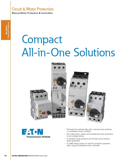
40Circuit & Motor ProtectionManual Motor Protectors & ControllersEATON CORPORATION 2009/2010 OEM Product GuidesEliminate the overload relay with a manual motor protector or combination motor controllersGet a disconnect, starter, and overload and motor protection in one compact devicesA complete motor protector and remote control solution easily assembledsUL 508F ratings means no need for protection upstream when using a combination motor controllerCompactAll-in-One Solutions41Circuit & Motor ProtectionManual Motor Protectors & ControllersPRODUCT OVERVIEWEATON CORPORATION 2009/2010 OEM Product GuideManual Motor Protectors & Controllers Product OverviewXTPR RotaryXTSC Manual Motor ControllerXTFC Combination Motor ControllerPage Page 42Page 42Page 49Page 49Operator Style PushbuttonRotaryRotaryRotaryComponentsManual Motor ProtectorManual Motor ProtectorManual Motor Protector Contactor Connector Kit Manual Motor Protector Contactor Connector Kit Line Side Adapter UL 508 Type E —Yes, Line Side Adapter ——UL 508 Type F ———Yes, Line Side Adapter Branch Motor Circuit FunctionsDisconnectController (manual)Short Circuit Protection Motor Overload Protection DisconnectController (manual)Short Circuit Protection Motor Overload Protection DisconnectController (manual & remote)Short Circuit Protection Motor Overload Protection DisconnectController (manual & remote)Short Circuit Protection Motor Overload Protection FLA Range0.1 – 25A0.1 – 65A0.1 – 65A0.1 – 65AM a n u a l M o t o r P r o t e c t o r s & C o n t r o l l e For our complete product offering, see the Control Products Catalog (CA08102001E).Circuit & Motor ProtectionManual Motor Protectors & ControllersCATALOG SELECTIONEATON CORPORATION 2009/2010 OEM Product Guide XT IEC Manual Motor Protectors — Catalog Numbering System016 = 16A 025 = 25A 032 = 32A 040 = 40A050 = 50A058 = 58A 063 = 63A For our complete product offering, see the Control Products Catalog (CA08102001E).43Circuit & Motor ProtectionManual Motor Protectors & ControllersPRODUCT SELECTIONEATON CORPORATION 2009/2010 OEM Product GuideXTPB Pushbutton Manual Motor Protectors — Global and North American Ratings Motor Protective Device with Thermal and Magnetic Trip0.160.250.40.630.1 – 0.160.16 – 0.250.25 – 0.40.4 – 0.63 2.23.55.68.8——0.060.09—0.060.090.12—0.060.120.18—0.060.120.250.060.120.180.25ባባባባባባባባባባባባባባባባX TPBP16BC1X TPBP25BC1X TPBP40BC1X TPBP63BC111.62.540.63 – 11 – 1.61.6 – 2.52.5 – 4142235560.120.250.370.750.250.550.751.50.250.551.11.50.370.751.12.20.551.11.53ባባ1/21ባባ1/211/23/4121/211-1/23X TPB001BC1X TPB1P6BC1X TPB2P5BC1X TPB004BC16.31012 4 – 6.36.3 – 108 – 1288140168 1.1 2.2 3 2.2 4 5.5 3 4 5.5 3 4 5.5 4 7.5 111-1/2331-1/23337-1/27-1/251010X TPB6P3BC1X TPB010BC1X TPB012BC116202510 – 1616 – 2020 – 2522428035045.55.57.5912.591112.5912.51512.51522355557-1/2101015101520X TPB016BC1X TPB020BC1X TPB025BC1ቢ Select manual motor protectors by full load amperes. Maximum motor ratings (kW, hp) are for reference only.ባ In this range, calculate motor rating according to rated current. Specified values to NEC 430.6(A)(1).ote: N Service Factor (SF) — Setting I r of current scale in dependence of load factor:SF = 1.15 -> I r = 1 x I n mot SF = 1 -> I r = 0.9 x I n motXT IEC Manual Motor Protectorss ON / OFF rotary handle with lockout provision s Class 10 overload protection s Motor applications from 0.1A to 63As Built-in heater and magnetic trip elements to protect the motor s Adjustment dial for setting motor FLAsXTPR Rotary MMP with a lineside adapter is rated for UL 508 Type EM a n u a l M o t o r P r o t e c t o r s & C o n t r o l l e r sFor our complete product offering, see the Control Products Catalog (CA08102001E).Circuit & Motor ProtectionManual Motor Protectors & ControllersPRODUCT SELECTIONEATON CORPORATION 2009/2010 OEM Product Guide XT IEC Manual Motor ProtectorsXTPR Rotary Manual Motor Protectors with Screw Terminals — Global Ratings and North American Ratings Motor Protective Device with Thermal and Magnetic TripFrame B0.160.250.40.630.1 – 0.160.16 – 0.250.25 – 0.40.4 – 0.63 2.23.55.68.8——0.060.09—0.060.090.12—0.060.120.18—0.060.120.250.060.120.180.25ባባባባባባባባባባባባባባባባXTPRP16BC1XTPRP25BC1XTPRP40BC1XTPRP63BC111.62.540.63 – 11 – 1.61.6 – 2.52.5 – 4142235560.120.250.370.750.250.550.751.50.250.551.11.50.370.751.12.20.551.11.53ባ ባ1/21ባ ባ1/211/23/4121/211-1/23XTPR001BC1XTPR1P6BC1XTPR2P5BC1XTPR004BC16.3101216 4 – 6.36.3 – 108 – 1210 – 1688140168224 1.12.234 2.245.57.5345.59345.5947.511 12.51-1/23331-1/233537-1/27-1/2105101010XTPR6P3BC1XTPR010BC1XTPR012BC1XTPR016BC120253216 – 2020 – 2525 – 322803504485.55.57.5912.5151112.51512.51522152230557-1/257-1/210101525152030XTPR020BC1XTPR025BC1XTPR032BC1Frame D1625324010 – 1616 – 2525 – 3232 – 4022435044856045.57.5117.512.51520912.517.522915222412.522223037-1/2101057-1/210151020253015253040XTPR016DC1XTPR025DC1XTPR032DC1XTPR040DC150586540 – 5050 – 5855 – 65700812882141718.525303430373730374545555510——15——3040—40——XTPR050DC1XTPR058DC1XTPR063DC1ቢ Select manual motor protectors by full load amperes. Maximum motor ratings (kW, hp) are for reference only.ባ In this range, calculate motor rating according to rated current. Specified values to NEC 430.6(A)(1).ቤ Catalog number shown comes with screw terminals. For Frame B devices up to 16A, spring cage terminals are available.For spring cage terminals on line and load sides, insert a “C” into the catalog number in the 5th position — Example: XTPR C _BC1.For spring cage terminals on the load side only, insert an “SC” into the catalog number in the 5th and 6th positions — Example: XTPR SC _BC1.ote:N Service Factor (SF) — Setting I r of current scale in dependence of load factor:SF = 1.15 -> I r = 1 x I n mot SF = 1 -> I r = 0.9 x I n motFor our complete product offering, see the Control Products Catalog (CA08102001E).Circuit & Motor ProtectionManual Motor Protectors & ControllersPRODUCT SELECTIONEATON CORPORATION 2009/2010 OEM Product GuideXT IEC Manual Motor ProtectorsXTPR Manual Self-Protected Motor Starters — North American Ratings, UL 508 Type E ቢMotor Protective Device with Thermal and Magnetic Trip0.160.250.40.630.1 – 0.160.16 – 0.250.25 – 0.40.4 – 0.63 2.23.45.68.8ቤቤቤቤቤቤቤቤ1/21/21/21/21/21/21/21/2505050505050505050505050XTPAXLSA XTPAXLSA XTPAXLSA XTPAXLSA XTPRP16BC1XTPRP25BC1XTPRP40BC1XTPRP63BC111.62.540.63 – 11 – 1.61.6 – 2.52.5 – 414223556ቤቤ1/23/4ቤቤ1/211/23/4121/23/41-1/23505050505050505050505050XTPAXLSA XTPAXLSA XTPAXLSA XTPAXLSA XTPR001BC1XTPR1P6BC1XTPR2P5BC1XTPR004BC16.3101216 4 – 6.36.3 – 118 – 1210 – 168814016822413331-1/233537-1/27-1/210510——50504242505042425050——XTPAXLSA XTPAXLSA XTPAXLSA XTPAXLSA XTPR6P3BC1XTPR010BC1XTPR012BC1XTPR016BC120253216 – 2020 – 2525 – 32280350448557-1/257-1/210—1525———421818421818———XTPAXLSA XTPAXLSA XTPAXLSAXTPR020BC1XTPR025BC1XTPR032BC1Frame D1625324010 – 1616 – 2525 – 3232 – 4022435044856037-1/2101057-1/210101020253010253040505050505050505050505050XTPAXLSAD XTPAXLSAD XTPAXLSAD XTPAXLSAD XTPR016DC1XTPR025DC1XTPR032DC1XTPR040DC150586540 – 5050 – 5855 – 65700812882101515151515304040———656565656565———XTPAXLSAD XTPAXLSAD XTPAXLSADXTPR050DC1XTPR058DC1XTPR063DC1ቢ UL 508 Type E starters are assembled from a standard XTPR and a special incoming terminal line side adapter (XTPAXLSA or XTPAXLSAD). ባ Select manual motor protectors by full load amperes. Maximum motor ratings (kW, hp) are for reference only. ቤ In this range, calculate motor rating according to rated current. Specified values to NEC 430.6(A)(1).ote:N A UL 508 Type E self-protected manual combination starter (XTPR) consists of a manual motor protector (XTPR) and a UL listed line side adapter (e.g., XTPAXLSA). The Type E self-protectedmanual combination starter alone is a legitimate short-circuit protective device and disconnect means for the downstream motor, while the contactor has been added to provide remote operation of the motor circuit.For our complete product offering, see the Control Products Catalog (CA08102001E).46Circuit & Motor ProtectionManual Motor Protectors & ControllersPRODUCT SELECTIONEATON CORPORATION 2009/2010 OEM Product Guide XT IEC Manual Motor Protectors — AccessoriesAuxiliary ContactsIP65 Rotary Handle MechanismቢባቤDescriptionPkg. Qty.Catalog NumberComplete Kits — Includes Handle, Shaft and Required HardwareRotary Handle Mechanism IP65 Black — For use on main switches to IEC / EN 60204.1X TPAXRHMB Rotary Handle Mechanism IP65 Red / Yellow — For use on main switch with Emergency-Stop function to IEC / EN 60204.1X TPAXRHMRY Rotary Handle Mechanism IP65 Black — For use on main switches to IEC / EN 60204 where XTPR is mounted 90° from vertical.1 X TPAXRHM90B Rotary Handle Mechanism IP65 Red / Yellow — For use on main switch with Emergency-Stop function to IEC / EN 60204 where XTPR is mounted 90° from vertical.1X TPAXRHM90RYቢ With ON/OFF switch position and “+” (tripped), lockable with 3 padlocks, 4 – 8 mm hasp. Can be locked in the OFF position, if required.ባ Rotary handle mechanisms ship with door interlock disabled. See instruction publication with product for how to enable door interlock.ቤ Not for use with XTPAXFAEM20 early-make front-mount auxiliary contact.Shunt ReleaseCatalog Number — Screw Terminals Pkg. Qty.X TPAXSR120V60H X TPAXSR240V60H X TPAXSR480V60H X TPAXSR24VDC2222Undervoltage ReleaseCatalog Number — Screw Terminals Pkg. Qty.X TPAXUVR120V60H X TPAXUVR240V60H X TPAXUVR480V60H222For our complete product offering, see the Control Products Catalog (CA08102001E).47Circuit & Motor ProtectionManual Motor Protectors & ControllersPRODUCT SELECTIONEATON CORPORATION 2009/2010 OEM Product GuideXT IEC Manual Motor Protectors — Accessories Three-Phase Commoning Links ቢቢ Protected against accidental contact. B-Frame short circuit proof Ue = 690V, Iu = 63A; D-Frame short circuit proof Ue = 690V, Iu = 128A. Frame B links can be combined by rotating mounting.Frame D links cannot be combined.Incoming Terminal for Three-Phase Commoning Link ቢFor Use with...Pkg Qty.Catalog Number B-Frame XTPR, XTPB5X TPAXITቢ For three-phase commoning link, protected against accidental contact, Ue = 690V, Iu = 63A;for conductor cross-sections: 2.5 – 25 mm 2 stranded; 2.5 – 16 mm 2 flexible with ferrules, AWG 14-6.Line-Side Adapter ቢFor Use with...Pkg Qty.Catalog Number B-Frame XTPR to Create a UL 508 Type E/F Manual Combination Starter5X TPAXLSAD-Frame XTPR to Create a UL 508 Type E/F Manual Combination Starter1X TPAXLSAD ባቢ XTPAXLSA is for three-phase commoning link, finger- and back-of-hand proof, Ue = 690V,Iu = 60A; for conductor cross sections: 2.5 – 25 mm 2 stranded, 2.5 – 16 mm 2 flexible with ferrule, AWG 14-6.ባ XTPAXLSAD cannot be combined with three-phase commoning links.For our complete product offering, see the Control Products Catalog (CA08102001E).M a P r o t e c t o rCircuit & Motor ProtectionManual Motor Protectors & ControllersPRODUCT SELECTIONEATON CORPORATION 2009/2010 OEM Product Guide XT IEC Manual Motor Protectors — AccessoriesNon-Reversing StartersXTPB Pushbutton Manual Motor Protectors — North American Usage ቢባIP65NEMA3R, 4X, 12, 13XTPB MMP Only or with: XTPAXFA..., XTPBXFAEM20, XTPAXSA..., XTPAXUVR..., XTPAXSR..., XTPAXCLWith actuating diaphragmXTPBXENAS65IP65NEMA3R, 4X, 12, 13XTPB MMP Only or with: XTPAXFA...,XTPBXFAEM20, XTPAXUVR..., XTPAXSR..., XTPAXCL With Emergency-Stop (E-Stop)pushbutton actuator, Red-YellowXTPBXENASES65B-Frame (0.1 – 32A) XTPR Rotary Manual Motor Protectors — North American Usage ቤIP55NEMA 1, 12, 3RB-Frame XTPR Only or with: XTPAXSA...and XTPAXFA..., XTPAXUVR...and XTPAXFA..., XTPAXSR...and XTPAXFA..., XTPAXCLWith red/yellow rotary handle for use as Emergency-Stop switch to VDE 0113XTPAXENAS55RY D-Frame (10 – 65A) XTPR Rotary Manual Motor Protectors ብቦIP65NEMA 1, 12, 3R, 4XD-Frame XTPR Only or with: XTPAXFA..., XTPAXFAEM20, XTPAXSA..., XTPAXSATR..., XTPAXUVR..., XTPAXSR..., XTPAXCLWith red/yellow rotary handle for use as Emergency-Stop switches to IEC / EN 60204XTPAXENCSD65RYቢ Built-in terminal for PE(N).ባ North American enclosures come with conduit adapters for use with 1/2” NPT.ቤ Built-in N and PE terminal, lower part without knockouts.ብ Integrated terminal for PE(N) connection.ቦ % Metric knockouts:Top ÷ bottom: M25/M32 In backplate: M25/M32 Control cable entry: M20For our complete product offering, see the Control Products Catalog (CA08102001E).。
ContentsPagen o i t p i r c s e D Introduction . . . . . . . . . . . . . . . . . . . . . . . . . . . . . 2Installation . . ............................. . . 2Installation Instructions for Auxiliary Switch for DK, KDB, KD, HKD,KDC, KW, HKW, KWC, Circuit Breakers, Molded Case Switches, and K-Frame Motor Circuit Protector2Installation Instructions for DK, KDB, KD, HKD, KDC, KW, HKW, KWC, Circuit Breakers, Molded Case Switches, and K-Frames Motor Circuit ProtectorsEATON CORPORATION The recom mendations and informa tion contained herein are based on Ea ton expe rience and judgm ent, butshould not be considered to be all-incl usive or c overing every application or circum stance which m ay arise. If any questions arise, contact Ea ton for further informa-tion or instructions.1. INTRODUCTIONGeneral InformationThe auxiliary switch (Fig. 1-1) indicates circuit breaker contacts status, and is used for remote signaling and system interlocking purposes. The switch consists of one or two single-pole double- throw (SPDT) switches assembled to a plug-in module. The plug- in module is mounted in slots in the top of the trip unit; it occupi- es the accessory cavity in the circuit breaker frame, and is positio- ned so that the switch actuator arm rests against the molded crossbar. Each SPDT switch has one "a" and one “b" contact. When the molded crossbar is in the contacts- closed position, the "a" contact of each SPDT switch is closed and the “b" contact is open. When the molded crossbar is in the tripped or contacts-open pos- i tion, the "a" contact is open and the ”b" contact is closed.DO NOT ATTEMPT TO INSTALL OR PERFORM MAINTENANCE ON EQUIPMENT WHILE IT IS ENERGIZED. DEATH, SEVERE PERSONAL INJURY, OR SUBSTANTIAL PROPERTY DAMAGE CAN RESULT FROM CONTACT WITH ENERGIZED EQUIPMENT.ALWAYS VERIFY THAT NO VOLTAGE IS PRESENT BEFORE PROCEEDING WITH THE TASK, AND ALWAYS FOLLOW GENERALLY ACCEPTED SAFE TY PROCEDURES.EATON IS NOT LIABLE FOR THE MISAPPLICATION OR MISIN-STALLATION OF ITS PRODUCTS.The user is cautioned to observe all recommendations,warnings, and cautions relating to the safety of person-nel and equipment as well as all general and localhealth and safety laws, codes, and procedures.Notes:Endu rance - 6000 electrical operations plus 4000 mechanical operations Pigtail wire size - No. 18 AWG (0.82 mm2) Terminal block is listed for use with one or two No. 18 to No. 14 AWG solid or stranded copper wire. Torque is 7 Ib-in (0.8 N.m). Non-inductive loadTable 1-1 lists electrical rating data for the auxiliary switch.T able 1-1. Auxiliary Swit ch Elect rical Rating Data Maximum Voltage (V) Maximum Current (A) 60012525050/60 Hz DC DC620.50.25 2500Freq.Diele ctric Withstand Voltage (V)34441123Note: No more than three pigtail leads can be routed through the rear trough in the circuit breaker base.When the walking beam interlock is used with the circuit breaker, the rear trough cannot be used for accessory pigtail leads.the auxiliary switch.2. INSTALLATIONHKD, and KDC circuit breakers under UL File E64983.For sealed circuit breakers, Underwriters Laboratories,Inc. UL489 requires that internal accessories be insta-lled at the factory. The auxiliary switch is listed for factory installation under UL File E7819.Where local codes and standards permit and UL listing-lled in DK and KDB sealed circuit breakers. In this case, UL listing becomes invalid and the label should be removed.Before attempting to install the accessory, check that the catalog number is correct and that the rating ofDepending on the model ordered, connections for theauxiliary switch are in one of four forms. The standard wiring con guration is pigtail leads exiting the rear of the basedirectly behind the accessory. Optional con gurations include a terminal block mounted on the same side of the base as the accessory, leads exiting the side of the base where theaccessory is mounted, and leads exiting the rear of the base on the side opposite the accessory. The 18-inch long pigtail leads are color coded for identi cation; identi cation labels are provided for pigtail leads and terminal block pOints. For allowable locations of all accessories, refer to Frame Book 29-103.Fig. 1-1 Auxiliary Switch Installed in K-Frame Circuit Breaker Instruction Leaflet IL 29C122CE ective April 20153EATONON CORPORATION The auxiliary switch, shown in kit form in Fig. 2-1, can be installed in the right or left accessory mounting cavity of a 2-, 3-, or 4-pole circuit breaker. An auxiliary switch must be installed in the circuit breaker before the circuit breaker is mounted in an electrical system. To install the auxiliary switch, perform the following procedures:Note: A circuit breaker that is mounted in an electrical sys-tem must be removed to install the accessory. T o ensure correct accessory installation, the circuit breaker must be placed on a horizontal surface.Fig. 2-1. AuxiliaryFig. 2-2 Accessory Wiring OptiondSwitch KitBEFORE REMOVING A CIRCUIT BREAKER INSTALLED IN AN ELECTRICAL SYSTEM, MAKE SURE THE CIRCUITBREAKER IS SWITCHED TO THE OFF POSITION AND THERE IS NO VOLTAGE PRESENT WHERE WORK IS TO BEPERFORMED. SPECIAL ATTENTION SHOULD BE PAID TO REVERSE FEED APPLICATIONS TO ENSURE NO VOLTAGE IS PRESENT . THE VOLTAGES IN ENERGIZED EQUIPMENT CAN CAUSE DEATH OR SEVERE PERSONAL INJURY .2-1. Switch circuit breaker to OFF position.2-2. Disconnect and remove circuit breaker from installation and terminal conne Single Auxiliary Switch Plug-in Module with Pigtail LeadsWire Marking Label (Supplied with Double Aux.Switch Only)Connection Diagram Label (Pigtail Lead Label Shown)Accesory identification Label ctions.Note: For new circuit breaker installation, trip unit must be installed in circuit breaker before attempting to install auxiliary switch. Refer to I.L. 29C603, I.L. 29C604, orI.L. 29C605 for instructions on how to install the trip unit.2-3. Remove cover screws and cover.Note: For an auxiliary switch having rear or oppositeside exiting pigtail leads, thread leads through center trough inside of case before attempting to insertmounting bracket. Pigtail leads exiting in this manner should be eased through trough as mounting bracket is inserted into trip unit retaining slots. Use center slot for leads exiting side of the circuit breaker.CAUTIONPIGTAIL WIRES SHOULD BE FORMED AND ROUTED TO CLEAR ALL MOVING PARTS WHEN ACCESSORY IS PROPERLY INSTALL-ED. PIGTAIL LEADS COULD BE DAMAGED IF IN CONTACT WITH MOVING PARTS.2-5. Insert the auxiliary switch as described in the following steps (Fig. 2-3):Fig. 2-3. Auxiliary Switch Installation Positions2-4. Route wiring to meet installation requirements. (Fig. 2-2)Installation Instructions for DK, KDB, KD, HKD, KDC, KW, HKW, KWC, Circuit Breakers, Molded Case Switches, and K-Frames Motor Circuit ProtectorsInstruction Leaflet IL 29C122C4EATON CORPORATIONa. Slide auxiliary switch plug-in module into slots untilretaining clip snaps into trip unit. Auxiliary switch operating arm(s) must be between accessory operating projection on molded crossbar and arc extinguisher. For terminal block assemblies, slide terminal block into mounting slot on side of base as plug-in module is being positioned.b. If required, complete routing of leads to opposite-side through rear wiring trough.c. For double auxiliary switch pigtail leads, attach wire marking labels to bundle of three leads for each switch. (Markers designated 1 and 2 are provided.)WHEN INSTALLING CIRCUIT BREAKER COVER, MAKE SURE THAT ALL INTERNAL PARTS ARE IN PLACE:• SLIDING HANDLE BARRIE RS ARE POSITIONED SO THAT THE HANDLE OPENING IS ALIGNED WITH THE HANDLE.• PIG T AIL LEADS ARE CLEAR OF CO VER.WHEN REMO VED AND REIN STALLE D , THREAD-FORMING SCREWS TRY TO REFORM THE THREADS IN THE CIRCUIT BREAKER BASE . CARE SHOULD BE TAKEN EVERY TIME A THREAD-FORMING SCREW IS USED TO ENSURE THAT THE SCREW STARTS IN THE ORIGINAL THREAD S .D AMA GED THREADS CAN RESU LT IN IMPROPER CIRCUIT BREAKER CO VER RETENTION.Fig. 2-4. Cover Screw Installation PositionsFig. 2-5. Preferred Mounting Location for Accessory Nameplate LabelsInstallation Instructions for DK, KDB, KD, HKD, KDC, KW, HKW, KWC, Circuit Breakers, Molded Case Switches, and K-Frames Motor Circuit ProtectorsInstruction Leaflet IL 29C122C2-6. With circuit breaker handle in OFF position and accessory pigtail leads (if used) routed as required, install circuit breaker cover. Secure with pan-head screws followed by thread-forming screws, asshown in Fig. 2-4.2-7. Remove and discard UL listing label on DK and KDB circuit breakers only.2-8. Place accessory labels (supplied with kit) on circuit breaker. (See Fig. 2-5.)Note: Accessory labels show connection diagram for auxiliary switch . Pigtail leads are color coded red, black,and blue.2-9. est auxiliary switch(es). Connect continuity tester or ohmmeter across pigtail leads or terminal block connections. Check continuity as follows:a. Circuit breaker handle OFF "a" contact(s) open. "b" contact(s) closed.b.Circuit breaker handle ON "a" contact(s) closed. "b" contact(s) open. c. Press PUSH-TO-TRIP button "a" contact(s) open "b" contact(s) closed.d. If auxiliary switch(es) fails test, make sure thatauxiliary switch(es) module is properly seated in trip unit slots. If auxiliary switch(es) appears to be correctly installed and the problem persists,contact CutlerHammer.__________________2-10. Install circuit breaker.2-11. Connect auxiliary switch as required (see Fig. 2-6).Fig. 2-6. Auxiliary Switch Connection Diagram Eaton assumes no responsibility for malfunctioning accessories installed by the customer.121324P 3P 12Screw, No. 8x 1.63 Inch, Flat Head, Cross-Recessed,Thread Forming.Screw .190-32 x .3125 Inch Pan Head, Cross-Recessed. Note: Hatched lines show additional pole and screw for 4-pole circuit breaker.2124P 13P 213P 213P 4P5EATON CORPORATION NOTES:Installation Instructions for DK, KDB, KD, HKD, KDC, KW, HKW, KWC, Circuit Breakers, Molded Case Switches, and K-Frames Motor Circuit ProtectorsInstruction Leaflet IL 29C122CE ective April 2015NOTES:Installation Instructions for DK, KDB, KD, HKD, KDC, KW, HKW, KWC, Circuit Breakers, Molded Case Switches, and K-Frames Motor Circuit ProtectorsInstruction Leaflet IL 29C122CE ective April 20156 EATON CORPORATION 7EATON CORPORATION NOTES:Installation Instructions for DK, KDB, KD, HKD, KDC, KW, HKW, KWC, Circuit Breakers, Molded Case Switches, and K-Frames Motor Circuit ProtectorsInstruction Leaflet IL 29C122CEaton Corporation Electrical Group1000 Cherrington Parkway Moon Township, PA 15108United State877-ETN-CARE (877-386-2273)© 2014 Eaton Corporation All Rights ReservedPrinted in Dominican Republic Publication No. IL 29C122C Part No. 6632C64H04April 2015The instructions for installation, testing,maintenance, or repairherein are provided for the use of the product in general commercial applications and may not be appropriate for use in nuclear applica-tions. Additional instructions may be available upon specific request to replace, amend, or supplement these instructions to qualify them for use with the product in s afety-related applications in a nuclear facility.The information, recommendations,descriptions,and safety nota-tions in this document are based on Eaton ’s experience and judg-ment with respect to Retrofitting of Power Breakers. This instruction- al literature is published solely for information purposes and should not be considered all-inclusive.If further information is required, you should consult an authorized Eaton sales represen tative.The sale of the product shown in this literature is subject to the terms and conditions outlined in appropriate Eaton selling policies or other contrac tual agreement between the parties. This literature is not intended to and does not enlarge or add to any such contract.The sole source governing the rights and remediesof any purchaser of this equipment is the contract between the purchaser and Eaton.NO WARRANTIES, EXPRESSED OR IMPLIED, INCLUDING WARRANTIES OF FITNESS FOR A PARTICULAR PURPOSE OR MERCHANTABILITY, OR WARRANTIES ARISING FROM COURSE OF DEALING OR USAGE OF TRADE, ARE MADE REGARDINGTHE INFORMATION, RECOMMENDATIONS, AND DESCRIPTIONSCONTAINED HEREIN,In no event will Eaton be responsible to the purchaser or user in contract, in tort (including negligence), strict liability or otherwise for any special, indirect, incidental or conse-quential damage or loss whatsoever,including but not limited to damage or loss of use of equipment, plant or power system, cost of capital, loss of power,additional expenses in the use of existing power facilities, or claims against the purchaser or user by its cus-tomers resulting from the use of the information, recommendations and description contained herein.Installation Instructions for DK, KDB, KD, HKD, KDC, KW, HKW, KWC, Circuit Breakers, Molded Case Switches, and K-Frames Motor Circuit ProtectorsInstruction Leaflet IL 29C122C。
Protective DevicesAdd-on Residual Current Protection Unit PBSM Catalog1.1Protective DevicesAdd-on Residual Current Protection Unit PBSM (MW)• C ombining this device with a top-quality min-iature circuit breaker of type PLS. will form a top-quality RCBO unit (combined RCD/MCB device)• D raw-out connection bar locked in installation position• F or subsequent mounting onto 2-, 3-, 3+N- and 4-pole miniature circuit breakers PLS.• Rated current 40 and 63 ADescriptionSG182111.2Protective DevicesAdd-on Residual Current Protection Unit PBSM (MW)Type ACConditionally surge current-proof 250 A, type ACMax. nominal current of PLS./I D n (A)TypeDesignationArticle No.Units perpackageSG1781140/0.03PBSM-402/0032623231/2040/0.10PBSM-402/012623241/2040/0.30PBSM-402/032623251/2040/0.50PBSM-402/052623261/2040/1.00PBSM-402/12623271/2063/0.03PBSM-632/0032624261/2063/0.10PBSM-632/012624271/2063/0.30PBSM-632/032624281/2063/0.50PBSM-632/052624291/2063/1.00PBSM-632/12624311/202-pole SG1811140/0.03PBSM-403/0032625371/2040/0.10PBSM-403/012625381/2040/0.30PBSM-403/032625391/2040/0.50PBSM-403/052625411/2040/1.00PBSM-403/12625421/2063/0.03PBSM-633/0032625561/2063/0.10PBSM-633/012625571/2063/0.30PBSM-633/032625581/2063/0.50PBSM-633/052625591/2063/1.00PBSM-633/12625601/203-pole SG1821140/0.03PBSM-404/0032625681/1340/0.10PBSM-404/012625691/1340/0.30PBSM-404/032625701/1340/0.50PBSM-404/052625711/1340/1.00PBSM-404/12625721/1363/0.03PBSM-634/0032625901/1363/0.10PBSM-634/012625911/1363/0.30PBSM-634/032625921/1363/0.50PBSM-634/052625951/1363/1.00PBSM-634/12625961/134-pole1.3Protective DevicesAdd-on Residual Current Protection Unit PBSM (MW)Type AConditionally surge current-proof 250 A, sensitive to residual pulsating DC, type AMax. nominal current of PLS./I D n (A)TypeDesignationArticle No.Units perpackageSG1781140/0.03PBSM-402/003-A 2623281/2040/0.10PBSM-402/01-A 2623291/2040/0.30PBSM-402/03-A 2624201/2040/1.00PBSM-402/1-A 2624211/2063/0.03PBSM-632/003-A 2625301/2063/0.10PBSM-632/01-A 2625311/2063/0.30PBSM-632/03-A 2625321/2063/1.00PBSM-632/1-A2625331/202-pole SG1811140/0.03PBSM-403/003-A 2625431/2040/0.03PBSM-403/003-A-2301806341/2040/0.10PBSM-403/01-A 2625441/2040/0.30PBSM-403/03-A 2625451/2040/1.00PBSM-403/1-A 2625461/2063/0.03PBSM-633/003-A 2625611/2063/0.03PBSM-633/003-A-2301806351/2063/0.10PBSM-633/01-A 2625621/2063/0.30PBSM-633/03-A 2625631/2063/1.00PBSM-633/1-A2625641/203-pole SG1821140/0.03PBSM-404/003-A 2625731/1340/0.10PBSM-404/01-A 2625741/1340/0.30PBSM-404/03-A 2625751/1340/1.00PBSM-404/1-A 2625761/1363/0.03PBSM-634/003-A 2625971/1363/0.10PBSM-634/01-A 2625981/1363/0.30PBSM-634/03-A 2626001/1363/1.00PBSM-634/1-A2626021/134-pole1.4Protective DevicesAdd-on Residual Current Protection Unit PBSM (MW)Type GSurge current-proof 3 kA, type G (ÖVE E 8601)Max. nominal current of PLS./I D n (A)TypeDesignationArticle No.Units perpackageSG1781140/0.03PBSM-402/003-G2624221/202-pole SG1811140/0.03PBSM-403/003-G2625521/203-pole SG1821140/0.03PBSM-404/003-G2625771/134-pole Type SSelective + surge current-proof 5 kA, type SSG1781140/0.10PBSM-402/01-S 2624231/2040/0.30PBSM-402/03-S 2624241/2040/1.00PBSM-402/1-S 2624251/2063/0.10PBSM-632/01-S 2625341/2063/0.30PBSM-632/03-S 2625351/2063/1.00PBSM-632/1-S2625361/202-pole SG1811140/0.10PBSM-403/01-S 2625531/2040/0.30PBSM-403/03-S 2625541/2040/1.00PBSM-403/1-S 2625551/2063/0.10PBSM-633/01-S 2625651/2063/0.30PBSM-633/03-S 2625661/2063/1.00PBSM-633/1-S2625671/203-pole SG1821140/0.10PBSM-404/01-S 2625861/1340/0.30PBSM-404/03-S 2625871/1340/1.00PBSM-404/1-S 2625881/1363/0.10PBSM-634/01-S 2626031/1363/0.30PBSM-634/03-S 2626051/1363/1.00PBSM-634/1-S2626071/134-pole1.5Protective DevicesAdd-on Residual Current Protection Unit PBSM (MW)Type S/ASelective + surge current-proof typ. 5 kA, sensitive to residual pulsating DC, type S/AMax. nominal current of PLS./I D n (A)TypeDesignationArticle No.Units perpackageSG1781163/0.30PBSM-632/03-S/A1670171/202-pole SG1811163/0.30PBSM-633/03-S/A1670201/203-pole SG1821163/0.30PBSM-634/03-S/A1670231/134-pole1.6Protective DevicesAdd-on Residual Current Protection Unit PBSM (MW) - Technical DataSpecifications | Add-on Residual Current Protection Unit PBSMDescription• Add-on residual current unit • Line voltage-independent tripping • B y combining this device with a top-quality miniature circuit breaker type PLS. a top-quality RCBO unit (combined RCD/MCB device) is formed.• Rated current 40 and 63 A • P ermits combinations with a variety of characteristics thanks to the differ-ent rated currents and characteristics of the PLS.-miniature circuit breakers which can be connected • C omrehensive range of accessories suitable for subsequent installation onto PLS.• T he test key “T” must be pressed every 6 month. The system operator must be informed of this obligation and his responsibility in a way that can be proven (self-adhesive RCD-label enclosed). The test intervall of 6 month is valid for residential and similar applications. Under all other conditions (e.g. damply or dusty environments), it’s recommended to test in shorter intervalls (e.g. monthly).• P ressing the test key “T” serves the only purpose of function testing the residual current device (RCD). This test does not make earthing resistance measurement (R E ), or proper checking of the earth conductor condition redundant, which must be performed separately.• T ype -A : Protects against special forms of residual pulsating DC which have not been smoothed.• T ype -G : High reliability against unwanted tripping. Suitable for any circuit where personal injury or damage to property may occur in case of unwanted tripping.• T ype -S : Selective residual current device, either sensitive to AC, type -S, or sensitive to pulsating DC, type -S/A, for protection against special forms of residual pulsating DC which have not been smoothed. Suitable for systems with surge arresters downstream of the RCD.Accessories (on PLS.):Auxiliary switch for subsequent installation ZP-IHK 286052ZP-WHK 286053Tripping signal contact for subsequent installation ZP-NHK 248437Shunt trip release ZP-ASA/..248438, 248439Undervoltage releaseZ-USA/..248288-248291Additional terminal 35 mm 2BB-UL-TEPA/35169823Accessories:Cover cap for busbar mounting bracket In the scope of delivery Disposable cylinder head bolt with slotIn the scope of delivery1.7Protective DevicesAdd-on Residual Current Protection Unit PBSM (MW) - T echnical DataTechnical DataPBSMElectricalDesign according toCurrent test marks as printed onto the deviceIEC/EN 61009Tripping instantaneous 250 A (8/20 μs), surge current proof Type G10 ms delay 3 kA (8/20 μs), surge current proofType S40 ms delay 6 kA, selective disconnecting functionRated voltage U n230/400 V ACLimits operation voltage test circuit2-pole, 30 mA196-264 V2-pole, 100, 300, 500, 1000 mA196-456 V3-pole, 30 mA340-456 V3-pole, 30 mA-230196-264 V3-pole, 100, 300, 500, 1000 mA196-456 V4-pole, 30 mA340-456 V4-pole, 100, 300, 500, 1000 mA196-456 VRated frequency50 HzRated current I n£ 40 A, £ 63 ARated tripping current ID n 30, 100, 300, 500, 1000 mARated non-tripping current ID no 0.5 I nSensitivity AC and pulsating DCRated breaking capacity I cn same as connected PLS. up to max. 10 kARated fault breaking capacity ID mU n = 230 V 6 kAU n = 400 V 3 kAMechanicalFrame size45 mmDevice height90 mmDevice width70 mm (2p), 107,5 mm (3p), 125 mm (4p)Mounting fix mounted onto PLS.Degree of protection, built-in IP40Fastening screw M 2.5 (slotted one-way cheese head screw; > 0.6 Nm Upper and lower terminals lift terminalsTerminal protection finger and hand touch safe, DGUV VS3, EN 50274 Terminal capacityRigid conductors 1 x (1 - 35) mm2Flexible conductors (with wire end sleeve) 1 x (0.75 - 35) mm2Busbar thickness 0.8 - 2 mmOperating temperature -25°C to +40°CStorage- and transport temperature-35°C to +60°CResistance to climatic conditions25-55°C/90-95% relative humidity according to IEC 60068-2Connection diagrams2-pole 3-pole 4-poleDimensions (mm)EatonEMEA Headquarters Route de la Longeraie 71110 Morges, Switzerland © 2021 EatonAll Rights ReservedPublication No. CA019037EN 9010238177871Eaton Industries (Austria) GmbH Scheydgasse 421210 Vienna AustriaFollow us on social media to get the latest product and support information.Eaton is a registered trademark.To contact us please visit https:///us/en-us/support/international-support-contacts.htmlFor technical questions please contact your local Eaton team.Changes to the products, to the information contained in thisdocument, and to prices are reserved; as are errors and omissions.Only order confirmations and technical documentation by Eaton is binding. Photos and pictures also do not warrant a specific layout or functionality. Their use in whatever form is subject to prior approval by Eaton. The same applies to trademarks (especially Eaton, Moeller,and Cutler-Hammer). The Terms and Conditions of Eaton apply, as referenced on Eaton Internet pages and Eaton order confirmations.Eaton’s electrical business is a global leader with deep regionalapplication expertise in power distribution and circuit protection; power quality, backup power and energy storage; control and automation; life safety and security; structural solutions; and harsh and hazardous environment solutions. Through end-to-end services, channel and an integrated digital platform & insights Eaton is powering what matters across industries and around the world, helping customers solve their most critical electrical power management challenges.For more information, visit .。
2015年8月用户手册重要注意事项,请阅读本用户手册所讨论的产品服从伊顿公司销售文件规定的条件。
解释本设备购买者的权利和赔偿的唯一的依据是伊顿公司销售文件中规定的条件。
本手册包括的信息、建议和描述不构成任何质保条件、表达或者暗示(包括适合于特定的目的工者商业行为的质保条件),不构成销售过程和使用过程引起的质保条件。
伊顿公司不为使用本手册包括的信息、建议和描述面产生的后果负任何责任,其范围包括但不限于下述情况:购买或者用户的合同、侵权行为(包括疏忽),严格的赔偿责任,特别的或间接的事故,产生的损失,资金的损失,电能的损失,附加的费用,遭到的索赔。
本手册包含的信息随时会有调整,恕不另行通知。
前言1. 前言 (1)1.1系统概述 (1)1.1.1系统类型 (1)1.1.2 系统构造 (1)1.2用户手册 (1)1.2.1 适用人群 (1)1.2.2 手册构成 (1)2. 安全指导 (2)2.1 总论 (2)2.1.1人员安全 (2)2.1.2安全标准 (2)2.2 操作室安全 (2)2.2.1操作净距 (2)2.2.2 入口 (3)2.2.3防火装置 (3)2.2.4 警示标志说明 (3)2.2.5 火灾发生时做什么 (3)3.包装 (4)3.1包装 (4)3.2 收货 (4)3.3 搬运 (4)3.4 存放 (4)4. 产品描述 (5)4.1 基本设计 (5)4.2主母线系统 (6)4.3配电母线系统 (7)4.4马达启动和配电抽屉单元 (8)4.4.1马达启动和配电抽屉单元 (8)4.4.2MCC抽屉单元的设计原则 (9)4.4 ACB空气断路器单元 (9)4.5电缆连接 (10)4.6安全性能 (10)4.7 通用的技术参数 (10)4.8接线可能性及范围 (10)5.安装 (11)5.1现场安装准备 (11)5.2 并柜 (11)5.2.1使用鱼型排连接母线 (11)5.2.2 N排及PE排连接安装 (12)5.3系统电缆连接 (13)5.3.1一次电缆连接 (13)5.3.2二次回路连接 (14)5.4 系统调试 (14)5.4.1 元器件调试 (14)5.4.2 基本检查 (14)5.4.3 设备首次通电 (15)6.操作 (16)6.1 断路器操作 (16)6.2 抽屉 (16)6.3 扩展 (17)6.3.2 扩展的种类 (17)6.4拆卸 (17)7. 检验,维护及维修 (19)7.1 日志 (19)7.2 一般性的检查和维护 (19)7.3 开关柜元件及部件维护 (19)7.4 开关柜维护的频率 (19)8. 附录 (20)1. 前 言1.1系统概述Power Xpert DX是Eaton基于全球平台打造的全新一代低压配电及马达控制中心,具有更加安全、可靠、灵活的特点。
序言 0第一章控制系统的功能 (1)1.1电梯基本功能 (1)1.2选配功能 (4)第二章控制系统的组成与安装 (6)2.1控制系统的组成 (6)2.2控制系统的安装 (10)第三章液晶界面操作及参数说明 (14)3.1概述 (14)3.2键操作说明 (14)3.3液晶显示流程图及参数说明 (15)3.4监视窗口及操作说明 (19)附录一故障代码及说明 (22)序言ECS-MC2000/MC3000电梯控制系统是我公司在原有的ECS-MC控制系统基础上设计开发出的智能化更高、功能更强、调试与维护更方便的高技术产品。
它除了具有一般电梯控制系统的基本功能外,在系统参数设置、电梯功能选择、电梯调试与维护、现场适应能力等各方面有独到之处。
本系统的基本控制方式为串行通讯(CAN总线)与变频调速;可满足电梯楼层64层以下,电梯速度小于4米/秒,包括永磁同步电机在内的各种电梯电机的控制要求。
MC2000/MC3000型电梯电脑控制器的主板核心芯片是国际著名工业用单片机制造商FUJITSU的内部具有32位处理器的高端产品,集成度、可靠性堪称世界一流;软件设计充分体现了功能齐备,参数设置界面层次分明,调试及故障诊断信息充分,抗干扰能力强及干扰强度评价独具匠心的技术特点。
对电梯控制系统以外的电气元件设计了诊断与检测界面。
使电梯故障判断有的放矢,真正使该电梯控制系统做到了高性能与可靠性的完美统一,高水平与实用性的完美统一,高科技与应用简便的完美统一。
警告用户在使用本系统时应严格按照国家电梯标准的要求进行作业,并且详细阅读本系统所使用的说明书。
上述文件中涉及人身安全的部分均作为本系统对使用者的警告。
注意说明书中的符号与框图可能有更改,用户应以随机图纸为准。
第一章控制系统的功能1.1 电梯基本功能1.1.1 检修运行系统具有三组(或两组)检修开关。
优先级别由高至低分别为:轿顶检修开关,轿内检修开关(如果有此开关),控制柜紧急电动运行开关。
Eaton EX 1500Eaton EX700/1000/1500/2200/3000 VAEaton EX Rack/Tower versatility提供人性化的电源保护方案:• 服务器,数据存储及网络设备• VoIP 电话业务• 医疗设备 -工业加工零切换时间高品质在线式UPS1. 实现高可用性• 双转换在线式UPS ,具有电压频率独立调节(VFI)功能,配有静态旁路及PFC 功率因数校正功能• Powershare 。
Eaton EX 输出电源插座可独立受控断开负载,从而大限度的延长最关键负载后备时间。
作为标准功能它还支持远程重启及顺序启动功能• 旁路热插拔模块。
支持UPS 在线热插拔,实现不中断供电的情况下更换UPS• 延长后备时间。
可向Eaton EX 系列添加1至4组EXB 电池电池扩展模块。
Eaton EX 3000XL 系列配有一台内置式快速充电器,可额外延长后备时间2. 可压缩总持有成本(TCO )• 操作简便。
多语种LCD 显示屏。
能够全方位访问测量和设置菜单• 远程监控。
全套选件均采用附送的Solution-Pac 软件:支持 HTML 格式访问的SNMP 卡,ModBus/Jbus 及干结点输出3. 灵活性Eaton EX 系列所独具的灵活性为在同类产品中的其它优势:• 安装结构。
Eaton EX 系列可通用于机架式/塔式可变RT2U 安装(特别适用于机架式安装)或RT3U 安装(特别适用于塔式或浅式机架)• 连接简便。
借助于FlexPDU 和HotSwap MBP 模块,可通过电源插座或端子排连接Eaton EX 。
可根据需要将其安装于机组的后部、侧面或顶部• 能够与低功率因数负载完全兼容。
Eaton EX 系列整机功率因数高达 0.9 (3000VA/2700 W 及2200VA/1980W, 1500VA/1350W, 1000VA/900W 及700VA/630W)• 通讯接口。
Eaton 165455RCD/MCB, 32A, 30mA, miniature circuit-breaker trip curve C, 1pole+N, residual current circuit-breaker trip characteristic: G. PFL4-32/1N/C/003-GGeneral specificationsEaton Moeller series xPole - PFL4 RCBO - residual-current circuit breaker with overcurrent protection165455PFL4-32/1N/C/003-G401508161973386 mm 75 mm 37 mm 0.207 kg CE MarkedCEProduct NameCatalog Number Model CodeEANProduct Length/Depth Product Height Product Width Product Weight Compliances Certifications32 AIs the panel builder's responsibility. The specifications for the switchgear must be observed.4.5 kAMeets the product standard's requirements.Is the panel builder's responsibility. The specifications for the switchgear must be observed.3Does not apply, since the entire switchgear needs to be evaluated.Meets the product standard's requirements.0 kA50 HzIs the panel builder's responsibility.20.03 AType G (ÖVE E 8601), AC current sensitive0 W69.5 mm eaton-xpole-pfl4-rcbo-catalog-ca019047en-en-us.pdfDA-DC-03_PFLeaton-xpole-combined-mcb-rcd-device-rcbo-packaging-manual-multilingual.pdfeaton-xpole-combined-mcb-rcd-device-rcbo-sticker-manual-multilingual.pdfIL019140ZURated operational current for specified heat dissipation (In) 10.11 Short-circuit ratingRated switching capacity (IEC/EN 61009)10.4 Clearances and creepage distances10.12 Electromagnetic compatibilityCurrent limiting class10.2.5 Lifting10.2.3.1 Verification of thermal stability of enclosures Rated short-circuit breaking capacity (EN 60947-2) Frequency rating10.8 Connections for external conductorsNumber of poles (total)Fault current ratingSensitivity typeHeat dissipation per pole, current-dependentBuilt-in depthFeatures Catalogs Certification reports Installation instructionsAnti-nuisance tripping versionConcurrently switching N-neutral10.9.3 Impulse withstand voltageIs the panel builder's responsibility.Number of polesSingle-pole + N10.6 Incorporation of switching devices and componentsDoes not apply, since the entire switchgear needs to be evaluated.10.5 Protection against electric shockDoes not apply, since the entire switchgear needs to be evaluated.Rated switching capacity4.5 kAEquipment heat dissipation, current-dependent6.1 WTripping characteristicC10.13 Mechanical functionThe device meets the requirements, provided the information in the instruction leaflet (IL) is observed.10.2.6 Mechanical impactDoes not apply, since the entire switchgear needs to be evaluated.10.9.4 Testing of enclosures made of insulating materialIs the panel builder's responsibility.Static heat dissipation, non-current-dependent0 WApplicationSwitchgear for residential and commercial applications10.3 Degree of protection of assembliesDoes not apply, since the entire switchgear needs to be evaluated.Voltage typeACNumber of poles (protected)1Leakage current typeACShort time-delayedHeat dissipation capacity0 WRelease characteristicCImpulse withstand currentSurge-proof, 3 kAProduct rangePFL4Width in number of modular spacings210.2.3.2 Verification of resistance of insulating materials to normal heatMeets the product standard's requirements.10.2.3.3 Resist. of insul. mat. to abnormal heat/fire by internal elect. effectsMeets the product standard's requirements.Voltage rating230 V10.9.2 Power-frequency electric strengthIs the panel builder's responsibility.Degree of protectionIP20Overvoltage categoryIIIPollution degree210.7 Internal electrical circuits and connectionsIs the panel builder's responsibility.10.10 Temperature riseThe panel builder is responsible for the temperature rise calculation. Eaton will provide heat dissipation data for the devices.Basic functionCombined RCD/MCB devicesRated current32 AEaton Corporation plc Eaton House30 Pembroke Road Dublin 4, Ireland © 2023 Eaton. All Rights Reserved. Eaton is a registered trademark.All other trademarks areproperty of their respectiveowners./socialmediaRCBOMeets the product standard's requirements.3 kAMeets the product standard's requirements.Meets the product standard's requirements.10.2.2 Corrosion resistanceSurge current capacity 10.2.4 Resistance to ultra-violet (UV) radiation 10.2.7 Inscriptions。
Power Defense circuit breakers Product guideA globally rated platform from EatonPower Defense E molded case circuit breakers (MCCBs) and insulated case circuit breakers (ICCBs) are globally certified to meet your local requirements, empowering you to build and design systems that can be used anywhere in the world. Wherever Eaton does business, Power Defense circuit breakers are there, backed by Eaton’s global support and fulfillment network, with the right resources in place to minimize your project lead-time and maximize your uptime. Integrating new products can be a challenge, which is why the Power Defense circuit breakersare available with online instructions, support and a product selector. These unique tools can help you engineer and deliver your projects quickly, ultimately helpingto improve your bottom line.The Power Defense circuit breakersfeature the Power Xpert T Release(PXR) electronic trip units, offeringpremium protection and communi-cation features allowing you to usefewer components and a simplifieddesign while keeping your systemconnected, your equipment andemployees protected, and yourcustomers informed. The PXR tripunit family has models that willcover all of your needs, includingfully programmable models thatenable ultimate customization andflexibility, as well as value modelsthat offer all of the benefits ofelectronic trip units, with simplesetup and coordination.PXR electronic trip units areequipped with the latest micro-processor technology includingindustry-first advanced algorithmsthat notify you when your powerdistribution circuit breaker needsto be maintained or replaced. Theyalso have the embedded abilityto accurately measure energyconsumption with no additionalmeters or equipment, deliveringcritical data about your powerdistribution system and energyuse in your facility.Whether you’re building productioncapacity or a legacy, the greenfactory of the future or thenewest high rise on the nexthorizon, Power Defense circuitbreakers will serve as guardianand protector as your ideas arerealized in concrete and steel.Power Defense circuitbreakers—a globally ratedplatform from EatonEATON Power Defense circuit breakersMolded case circuit breaker Insulated case circuit breakerPower Defense circuit breaker portfolioFrame PD-1Dimensions3.00 W x 5.50 H x 2.99 D inches (76.2 x 139.7 x 76.0 mm)Current range 15–125 AMaximum NEMA voltage 347 Y/600 Vac/250 Vdc Maximum IEC voltage 415 Vac/250 Vdc Certifications UL/CSA/CE/CCCInterrupting capacity at 480 Vac (kAIC)18, 25, 35, 50, 65, 85, 100100% UL rated options Current limiting optionsTrip unit options T/M fixed fixed• Through-cover accessoriesFrame PD-2Dimensions4.13 W x 6.00 H x 3.38 D inches (105.0 x 152.4 x 86.0 mm)Current range 15–225 AMaximum NEMA voltage 600 Vac/250 Vdc Maximum IEC voltage 690 Vac/250 Vdc Certifications UL/CSA/CE/CCCInterrupting capacity at 480 Vac (kAIC)25, 35, 50, 65, 85, 100100% UL rated options Current limiting optionsTrip unit options T/M fixed fixed PXR 10PXR 20PXR 20D PXR 25Electronic protection LSI, LSIG• Through-cover accessories • Available with 2 PXRcommunication relays• 1 Relay with Modbus RTUFrame PD-3Dimensions5.48 W x 10.13 H x 4.09 D inches (139.2 x 257.3 x 104.0 mm)Current range 45–600 AMaximum NEMA voltage 600 Vac/250 Vdc Maximum IEC voltage 690 Vac/250 Vdc Certifications UL/CSA/CE/CCCInterrupting capacity at 480 Vac (kAIC)25, 35, 50, 65, 85, 100100% UL rated options Current limiting optionsTrip unit options T/M fixed adjustable PXR 10PXR 20PXR 20D PXR 25Electronic protection LSI, LSIG, ALSI, ALSIG• Through-cover accessories • Available with 2 PXRcommunication relays• Field-interchangeable trip unitsFrame PD-4Dimensions8.25 W x 16.00 H x 4.06 D inches (209.6 x 406.4 x 103.1 mm)Current range 300–800 AMaximum NEMA voltage 600 Vac/250 Vdc Maximum IEC voltage 690 Vac/250 Vdc Certifications UL/CSA/CE/CCCInterrupting capacity at 480 Vac (kAIC)35, 50, 65100% UL rated optionsTrip unit options T/M fixed adjustable PXR 10PXR 20PXR 20D PXR 25Electronic protection LSI, LSIG, ALSI, ALSIG• Through-cover accessories • Available with 2 PXRcommunication relays• Field-interchangeable trip unitsFrame PD-5Dimensions8.25 W x 16.00 H x 5.50 D inches (209.6 x 406.4 x 139.7 mm)Current range 320–1200 A (UL) 320–1600 A (IEC)Maximum NEMA voltage 600 Vac/250 Vdc Maximum IEC voltage 690 Vac/250 Vdc Certifications UL/CSA/CE/CCCInterrupting capacity at 480 Vac (kAIC)50, 65, 85, 100, 150100% UL rated optionsTrip unit options PXR 20PXR 20D PXR 25Electronic protection LSI, LSIG, ALSI, ALSIG• Field-interchangeableaccessories• Available with 3 PXRcommunication relays• Field-interchangeable trip unitsFrame PD-6Dimensions 15.50 W x 16.00 H x 9.00 D inches (393.7 x 406.4 x 228.6 mm)Current range 700–2500 AMaximum NEMA voltage 600 Vac/250 Vdc Maximum IEC voltage690 Vac/250 Vdc Certifications UL/CSA/CE/CCCInterrupting capacity at 480 Vac (kAIC)65, 85, 100100% UL rated optionsTrip unit options PXR 20PXR 20D PXR 25Electronic protection LSI, LSIG, ALSI, ALSIG• Field-interchangeableaccessories• Available with 3 PXRcommunication relays • Field-interchangeable trip unitsFrame PD-NFDimensions 10.00 W x 14.17 H x 7.86 D inches (254.0 x 359.9 x 199.6 mm)(with cassette)Current range200–1200 A (UL 489 option)200–1600 A (IEC option)Maximum NEMA voltage 600 Vac Maximum IEC voltage 690 VacCertifications UL/CSA or CE/CCC Interrupting capacityat 480 Vac (kAIC)42, 50, 65100% UL ratedTrip unit options PXR 20PXR 25Electronic protection LSI, LSIG, ALSI, ALSIG• Field-interchangeable accessories • Available with 3 PXRcommunication relays• Field-interchangeable trip units • Stored energy mechanism • Front connect or rear connect; fixed or drawoutFrame PD-RFDimensions 15.76 W x 17.96 H x 9.45 D inches (400.3 x 456.2 x 240.0 mm)(with cassette)Current range800–3000 A (UL 489 option)800–4000 A (IEC option)Maximum NEMA voltage 480 Vac Maximum IEC voltage 690 VacCertifications UL/CSA or CE/CCC Interrupting capacityat 480 Vac (kAIC)65, 85, 100100% UL ratedTrip unit options PXR 20PXR 25Electronic protection LSI, LSIG, ALSI, ALSIG• Field-interchangeable accessories • Available with 3 PXRcommunication relays• Field-interchangeable trip units • Stored energy mechanism • Rear connect; fixed or drawoutEATON Power Defense circuit breakers• Imbedded Modbus RTU •Additional communications protocols, including Modbus TCP , webpage interface and PROFIBUS, available via Eaton’s Communications Adapter Modules (CAM)•CAM module relays that can be programmed for custom breaker and trip unit visibilityMetering capability •Current and voltage metering accurate to 0.5% of reading; power and energy metering accurate to 1% of reading •Voltage metering internal to trip unit with no need for external modulesincluded in the trip unit, but only used when no auxiliary power is connected•All PXRs store additional trip event details in their memory that can be easily accessed via the USB port by the PXPM softwareLCD display withprogrammable settings•Local availability to fully programmable settings, breaker diagnostics, visual customization,event records, injection testing and unit information•Industry-leading solution to reduce arc flash energy released during maintenance •Multiple programmable relays provide user customizable visibility into breaker and trip unit, such as status, trip events, alarms, and indication of ZSI, Arcflash Reduction Maintenance System or breaker health•PXR trip units equipped with micro-USB connection for secondary injection testing through your PC, saving you labor hours and the cost of expensive test kits•Configure trip unit settings with direct-to-trip unit or offline setup, including duplication of settings between units •Capture waveforms, monitor real-time power and energy readings, store up to 200 events, create printable test reports and customize display orientationEATON Power Defense circuit breakersMCCB PXR features● Standard ● Optional▲ Available through USB port (PXPM)Arcflash ReductionPower Xpert Release (PXR) electronic trip unitsICCB PXR features● Standard ● Optional▲ Available through USB port (PXPM)ICCB PXR 20Status indicatorBreaker healthZSI verification and testingNavigation buttonsProtection settings Battery trayLCD displayCause of trip LEDsEATON Power Defense circuit breakersArcflash ReductionWhat will you build? And how will you defend it?Eaton is a registered trademark. All other trademarks are property of their respective owners.Eaton1000 Eaton Boulevard Cleveland, OH 44122United States © 2021 EatonAll Rights Reserved Printed in USAPublication No. BR012016EN / Z25689November 2021For more information, call 1-877-ETN-CARE (1-877-386-2273),or visit /powerdefenseA globally rated platform from Eaton.When Power Defense circuit breakers safeguard your structure’s power system, you are getting the latest protection technology, engineered for the future: Industry 4.0 features such as built-in communications, advanced energy metering and algorithms that notify you when your circuit breaker needs maintenance, as well as zone selective interlocking technology that clears faults quickly and locally, preventing propagation into your system. Arc flash reduction options help protect your people with the fastest tripping speed technology, not to mention Eaton’s best-in-class support and service. Y ou are freeing yourself and your customers from concerns and gaining the sort of assurance that allows your people to move and plan with confidence. That’s why our defense is your best offense.Our defense isyour best offense.Follow us on social media to get the latest product and support information.。