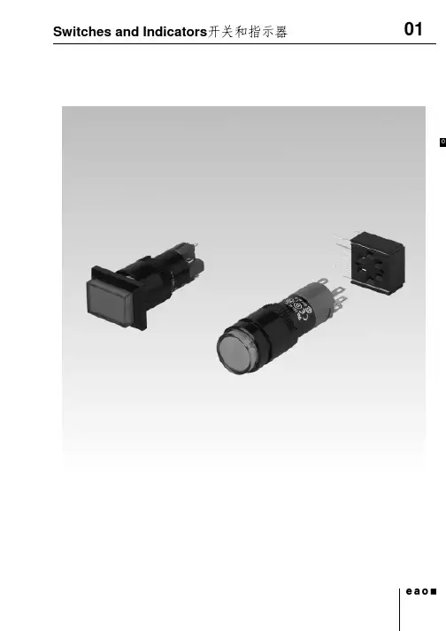
Toneluck微动开关 E43AN-AA13Ag-01 技术规格书
- 格式:pdf
- 大小:430.29 KB
- 文档页数:6
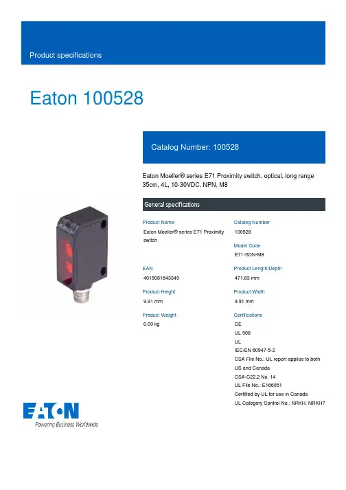
Eaton 100528Eaton Moeller® series E71 Proximity switch, optical, long range 35cm, 4L, 10-30VDC, NPN, M8General specificationsEaton Moeller® series E71 Proximity switch100528E71-SDN-M84015081643349471.83 mm 9.91 mm 9.91 mm 0.09 kgCE UL 508 ULIEC/EN 60947-5-2CSA File No.: UL report applies to both US and Canada CSA-C22.2 No. 14 UL File No.: E166051Certified by UL for use in Canada UL Category Control No.: NRKH, NRKH7Product NameCatalog Number Model Code EANProduct Length/Depth Product Height Product Width Product Weight Certifications0 V1 ms0 mm1Status indication of Operating voltage: Green LED Status indication of Switching state: Yellow LEDOther10 V-25 °COtherAccording to IEC/EN 60068-2-610 - 55 Hz, Amplitude 0.5 mm0 V0 mmNone20 mmInsulated materialCuboid Product Range Catalog Sensors – products, basic information, applicationseaton-proximity-switches-proximity-switch-dimensions-024.epseaton-proximity-switches-e71-proximity-switch-3d-drawing.epsIL05305006ZDA-CD-90_28292_002DA-CS-90_28292_002Rated control supply voltage (Us) at AC, 50 Hz - min Response timeDiameter sensorSafety type (IEC 61496-1)LED indicatorCable sheath materialRated control supply voltage (Us) at DC - min Ambient storage temperature - minInterface typeVibration resistanceNumber of outputs (protected semiconductor)Rated control supply voltage (Us) at AC, 50 Hz - max Sensor heightExplosion safety category for gasSensor lengthSensor materialEnclosure type CataloguesDrawingsInstallation instructions mCAD modelAmbient operating temperature - max55 °CWire sizeTransmission range of the safety field0 mSwitching frequency500 HzOutput current (mA) - max100 mASwitching voltage of OSSD at state high30 VFeaturesStraight beamRated control supply voltage (Us) at DC - max30 VVoltage rating - max30 VAmbient operating temperature - min-25 °CElectric connection typeConnector M8Output current at protected output - max0 mALight dot size0 mm²Sensing modeLight-/dark switchingWidth sensor12 mmVoltage typeDCNumber of outputs (semiconductor with signaling function) 1Product categoryE71 NanoView SeriesOperating distance - min0 mmOperating temperature - min-25 °CAdjustment typeManual adjustmentLoad currentMax. 100 mA (Ie)Rated switching distance (Sn)350 mmOperating modeSwitching principle: Adjustable bright/dark switchingOperating distance - max350 mmOptical surface materialPlasticLight typeInfrared lightOperating temperature - max55 °CConnection typePlug-in connection M8 x 14-wireSwitch function typeOtherDegree of protectionNEMA 4IP66Number of outputs (protected contact energized)Ambient storage temperature - max70 °CNumber of contact energized outputs with signalling function 0Rated control supply voltage (Us) at AC, 60 Hz - min0 VOperation agent-safety classSafety class 2Eaton Corporation plc Eaton House30 Pembroke Road Dublin 4, Ireland © 2023 Eaton. All rights reserved. Eaton is a registered trademark.All other trademarks areproperty of their respectiveowners./socialmediaProtection against polarity reversal Short-circuit protection Reflected-light beam NPNPlasticNoneNone Optical sensors0 V0 mm880 nm30 g, Mechanical, Shock duration 11 ms 350 mmFunctionsSwitching output type Enclosure material Explosion safety category for dust Laser protection class TypeRated control supply voltage (Us) at AC, 60 Hz - max Reflector distance - min Wavelength of the sensor Shock resistanceSwitching distance - max。
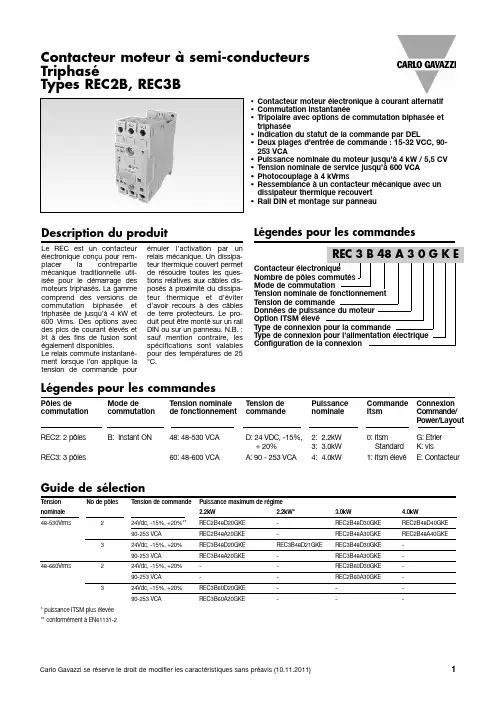
•Contacteur moteur électronique àcourant alternatif •Commutation instantanée•Tripolaire avec options de commutation biphasée et triphasée•Indication du statut de la commande par DEL•Deux plages d’entrée de commande :15-32VCC,90-253VCA•Puissance nominale du moteur jusqu’à4kW /5,5CV •Tension nominale de service jusqu’à600VCA •Photocouplage à4kVrms•Ressemblance àun contacteur mécanique avec un dissipateur thermique recouvert •Rail DIN et montage sur panneauDescription du produitLégendes pour les commandesLe REC est un contacteur électronique conçu pour rem-placer la contrepartie mécanique traditionnelle util-isée pour le démarrage des moteurs triphasé gamme comprend des versions de commutation biphasée et triphasée de jusqu’à4kW et 600Vrms.Des options avec des pics de courant élevés et I²t àdes fins de fusion sont également disponibles.Le relais commute instantané-ment lorsque l’on applique la tension de commande pourémuler l’activation par un relais mécanique.Un dissipa-teur thermique couvert permet de résoudre toutes les ques-tions relatives aux câbles dis-posés àproximitédu dissipa-teur thermique et d’éviter d’avoir recours àdes câbles de terre protecteurs.Le pro-duit peut être montésur un rail DIN ou sur un panneau.N.B.:sauf mention contraire,les spécifications sont valables pour des températures de 25°C.ContacteurNombre de pôles Mode de Tension nominale Tension de Données de Option ITSM élevéType de connexion Type de connexion Configuration de la Contacteur moteur àsemi-conducteurs TriphaséTypes REC2B,REC3BLégendes pour les commandesPôles deMode deTension nominale Tension de Puissance Commande Connexion commutation commutation de fonctionnement commande nominale Itsm Commande/Power/Layout REC2:2pôles B:InstantON48:48-530VCA D:24VDC,-15%,2:2.2kW 0:ItsmG:Etrier +20%3:3.0kW Standard K:visREC3:3pôles60:48-600VCAA:90-253VCA4:4.0kW1:Itsm élevéE:ContacteurT ension No de pôlesT ension de commandePuissance maximum de régime nominale 2.2kW2.2kW*3.0kW4.0kW48-530Vrms224Vdc,-15%,+20%**REC2B48D20GKE -REC2B48D30GKE REC2B48D40GKE 90-253VCAREC2B48A20GKE -REC2B48A30GKE REC2B48A40GKE 324Vdc,-15%,+20%REC3B48D20GKE REC3B48D21GKE REC3B48D30GKE -90-253VCAREC3B48A20GKE -REC3B48A30GKE -48-660Vrms224Vdc,-15%,+20%--REC2B60D30GKE -90-253VCA--REC2B60A30GKE -324Vdc,-15%,+20%REC3B60D20GKE ---90-253VCAREC3B60A20GKE---*puissance ITSM plus élevée **conformément àEN61131-2Guide de sélectionSpécifications des connexionsCONNEXIONS DE POWER (75°C,câbles en cuivre)CONNEXIONSDECOMMANDE (75°C,câbles en cuivre)Spécifications de la charge(45mm d’espace entre les unités adjacentes)Spécifications environnementales Spécifications du logementIsolationT ension diélectriquede résistance,de l’entréeàla sortie≥4000V AC rms*Valable pour version VCC.Pour versions VCA,voir Critère de performance N°2.**This product is designed and constructed as an EMC Class A device.The use of this product in residential applications could lead to radio interferences.In such applications,additional external filtering may be required.DimensionsEMC (Compatibilitéélectromagnétique)Connexion àl’intérieur de deltaDiagrammes des connexionsCourbes caractéristiques et cycles de fonctionnementCourbes :Nombre de cycles de commutation par heure par rapport àtONNombre maximum de démarrages permissibles en fonction de Tn et de TonAccessoiresAdaptateur du relais de surcharge du moteur.*Numéro de pièce:REC3ADAPTORPack quantité:5unitésCompatible avec:Fabricant Séries ExempleABB TA TA25DU-8.5 Siemens3RU113RU1126-1FB0*1adaptor is shipped with every REC unit。
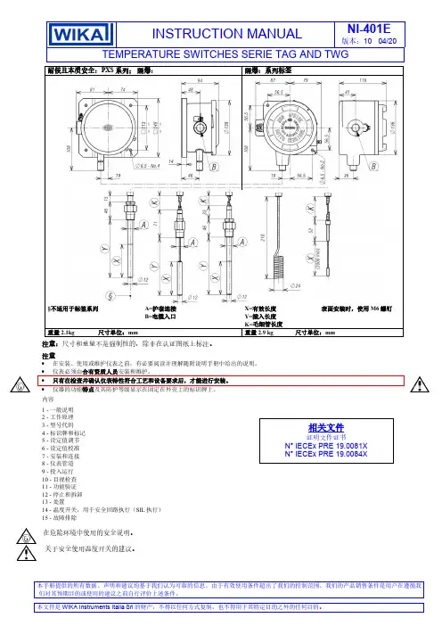
INSTRUCTION MANUALNI-401E版本:10 04/20TEMPERATURE SWITCHES SERIE TAG AND TWG本手册提供的所有数据、声明和建议均基于我们认为可靠的信息。
由于有效使用条件超出了我们的控制范围,我们的产品销售条件是用户在遵循我们对其预期目的或使用的建议之前自行评价上述条件。
耐候且本质安全:PXS 系列; 隔爆: 隔爆:系列标签§不适用于标签系列A=护套连接 B=电缆入口X=有效长度 Y=插入长度 K=毛细管长度 表面安装时,使用M6螺钉重量2.1kg尺寸单位:mm重量2.9 kg尺寸单位:mm注意:尺寸和重量不是强制性的,除非在认证图纸上标注。
注意• 在安装、使用或维护仪表之前,有必要阅读并理解随附说明手册中给出的说明。
• 仪表必须由合有资质人员安装和维护。
• 只有在检查并确认仪表特性符合工艺和设备要求后,才能进行安装。
•仪器的功能特点及其防护等级显示在固定在外壳上的标识牌上。
内容1 - 一般说明2 - 工作原理3 - 型号代码4 - 标识牌和标记5 - 设定值调节6 - 设定值校准7 - 安装和连接8 - 仪表管道9 - 投入运行 10 - 目视检查 11 - 功能验证 12 - 停止和拆卸 13 - 处置14 - 温度开关,用于安全回路执行(SIL 执行) 15 - 故障排除在危险环境中使用的安全说明。
关于安全使用温度开关的建议。
1 - 一般说明1.1 前言系列或型号的错误选择以及不正确的安装会导致故障并缩短仪器寿命。
不遵守本手册中给出的指示可能会对仪表、环境和人员造成损害。
1.2 允许的超量程工作温度可偶尔超过工作范围,前提是温度保持在仪表特性(设计温度)中规定的范围内。
超过工作范围的连续温度可应用于仪表,前提是仪表特性中明确说明了这些压力。
不得超过技术规范和额定值中规定的电流和电压值。
短暂的超量程会对开关产生破坏性影响。
1.3 机械振动一般会导致仪器某些部件的磨损或造成误跳闸。
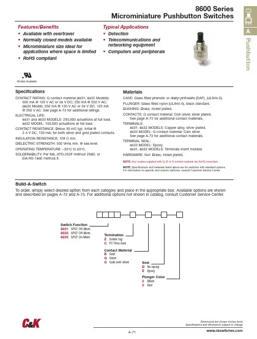
A-71Dimensions are shown: Inches (mm)Specifications and dimensions subject to change Pushbutton8600 SeriesMicrominiature Pushbutton SwitchesFeatures/Benefits• Available with overtravel• Normally closed models available • M icrominiature size ideal for applications where space is limited • RoHS compliantTypical Applications• Detection • T elecommunications andnetworking equipment• Computers and peripheralsSpecificationsCONTACT RATING: Q contact material (8631, 8632 Models):500 mA @ 120 V AC or 28 V DC; 250 mA @ 250 V AC; (8633 Model): 250 mA @ 120 V AC or 28 V DC; 125 mA @ 250 V AC. See page A-73 for additional ratings.ELECTRICAL LIFE:8631 and 8633 MODELS: 250,000 actuations at full load. 8632 MODEL: 100,000 actuations at full load.CONTACT RESISTANCE: Below 30 mΩ typ. initial @2-4 V DC, 100 mA, for both silver and gold plated contacts.INSULATION RESISTANCE: 109 Ω min.DIELECTRIC STRENGTH: 500 Vrms min. @ sea level.OPERATING TEMPERATURE: –30ºC to 65ºC.SOLDERABILITY: Per MIL-STD-202F method 208D, orEIA RS-186E method 9.MaterialsCASE: Glass filled phenolic or diallyl phthalate (DAP), (UL94V-0).PLUNGER: Glass filled nylon (UL94V-0), black standard.BUSHING: Brass, nickel plated.CONTACTS: Q contact material: Coin silver, silver plated.See page A-73 for additional contact materials.TERMINALS:8631, 8632 MODELS: Copper alloy, silver plated. 8633 MODEL: Q contact material: Coin silver. See page A-73 for additional contact materials.TERMINAL SEAL:8633 MODEL: Epoxy.8631, 8632 MODELS: Terminals insert molded.HARDWARE: Nut: Brass, nickel plated.NOTE: Any models supplied with Q, B or G contact material are RoHS compliant. NOTE: Specifications and materials listed above are for switches with standard options. For information on specific and custom switches, consult Customer Service Center.Build-A-SwitchTo order, simply select desired option from each category and place in the appropriate box. Available options are shown and described on pages A-72 and A-73. For additional options not shown in catalog, consult Customer Service Center.Switch Function 8631 SPST Off-Mom.8632SPST Off-Mom.8633 SPST On-Mom.Contact Material B Gold Q SilverG Gold over silverSealDNo epoxy E Epoxy Plunger Color 2 Black 3 RedModels AvailableTermination Z Solder lug C PC Thru-holeA-72Dimensions are shown: Inches (mm)Specifications and dimensions subject to changeP u s h b u t t o n8600 SeriesMicrominiature Pushbutton SwitchesPC MOUNTING8631, 8632 models only.8633 models only.8631, 8632 models only.MOM. = MomentaryNOTE: Caps available for plunger options, see page A-73.Z SOLDER LUGC PC THRU-HOLEA-73Dimensions are shown: Inches (mm)Specifications and dimensions subject to change PushbuttonOPTION CODECOLOR 2BLACK 3RED8600 SeriesMicrominiature Pushbutton SwitchesAVAILABLE HARDWARE.187(4,75).081(2,03).245 DIA.(6,22 )NOTE: Other cap colors available, consult Customer Service Center.E EPOXY SEALD NO EPOXY SEALNot available on 8631, 8632 models.Standard on 8633 model only.Not available on 8633 model.Standard on 8631, 8632 models.CapPART NO.785101000WHITE 785102000 BLACK 785103000 REDMaterial: Nylon Finish: Gloss* Note: See Technical Data section of this catalog for RoHS compliant and compatible definitions and specifications.1 CONTACTS & TERMINALS: Copper alloy, with gold plate over nickel plate.2 CONTACTS: Coin silver, with gold plate over nickel plate.3 TERMINALS: C opper alloy, with gold plate over nickel plate.8633 model only: Coin silver, with gold plate over nickel plate.4 CONTACTS: Coin silver, silver plated.5 TERMINALS: Copper alloy, silver plated. 8633 model only: coin silver.NOTE: Any models supplied with Q, B or G contact material are RoHS compliant. 8631, 8632 modelswith all options when ordered with G or Q contact material.Q contact material standard with C, Z terminations.。
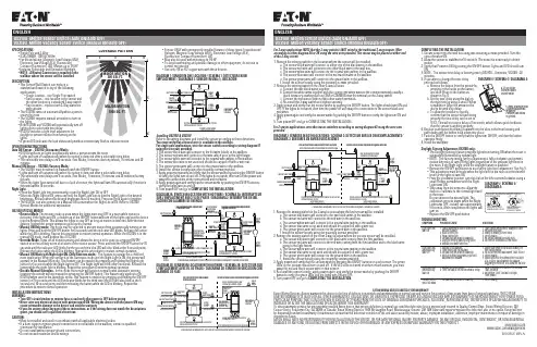
SPECIFICATIONS• Single Pole and 3-Way• 8.3A (1000W), 120V AC 60 Hz.• For Incandescent, Magnetic Low Voltage (MLV),Electronic Low Voltage (ELV), Fluorescent,Compact Fluorescent, LED, Motors up to 1/6 HP• Includes Selectable and Dimmable Nightlight• NOTE - A Neutral Connection is required in thewallbox where the sensor will be installedDESCRIPTION• This Sensor Wall Switch can replace astandard wall switch in any of the followingapplications:• Single location – one Single Pole switch• Two location – one location is the sensor andthe other location is a standard 3-way switch• Two location – replace both 3-Way switcheswith sensors• The OS310U turns on automatically when a personenters the room• The VS310U requires manual activation to turn onthe lights• Both OS310U and VS310U will automatically turn offlights after a selectable time delay• OS310U includes a light level adjustment fordaylight to prevent motion from turning on thelights• A green LED indicates the load status and provides a momentary flash to indicate motion OPERATION INSTRUCTIONSAuto ON Sensor – OS310U (Occupancy Mode):• OS310U will turn on lights automatically when a person enters the room• Lights will turn off automatically when no motion is detected after a selectable time delay• The selectable time delays are 5 seconds (Test Mode), 5 minutes (factory default), 15 minutes and 30 minutesManual ON Sensor – VS310U (Vacancy Mode):• The VS310U must be turned on manually with the ON/OFF button• Lights will turn off automatically when no motion is detected after a selectable time delay• The selectable time delays are 5 seconds (Test Mode), 5 minutes, 15 minutes and 30 minutes (factory default)• When the lights have turned off due to a lack of motion, the lights will turn ON automatically if motion is detected within 10 secondsNight Light• Press the Night Light lens momentarily to turn the Night Light ON or OFF• When the Night Light is ON, press and hold the Night Light lens to dim the Night Light to the desiredbrightness. Release when the desired brightness level is reached. Press and hold again to brighten• The OS310U can also operate as a Manual ON sensor when the Night Lite is ON. Refer to OS310USpecial Modes for additional explanationOS310U SPECIAL MODES• Reverse Mode: The reverse mode is used when the lights must stay OFF in a room while motion isdetected. If the lights are ON, a double tap of the ON/OFF button will turn off the lights and put the device into the Reverse Mode. This allows the lights to stay OFF as long as motion is detected. After the time delay is finished the sensor operation goes back to normal• Manual ON Only mode: This mode may be selected to prevent motion from automatically turning on the lights. Press and hold the ON/OFF button for 5 seconds until the indicator LED blinks. Release the button while the LED is blinking. Repeat this procedure to restore normal operation. While the OS310U is in the manual ON mode, it will behave like a VS310U• Override Mode: Turns off all motion sensing and allows the device to be used as a regular ON/OFFswitch or in the unlikely event of a failure of the motion sensor. Press and hold the ON/OFF button for 10 seconds until the indicator LED blinks for the second time (the LED will also blink at the 5 second point).Release the button while the LED is blinking. Repeat this procedure to restore normal operation• Manual ON Mode with Night Light ON (Child Bedroom mode): This feature is popular for a child bed room application. When the sensor is in the Automatic mode and the Night Light is ON, the sensor will operate in the Manual ON mode. This feature can be enabled by pressing and holding the Night Light button for 5 seconds while the Night Light is OFF. The Night Light will blink after 5 seconds. Release the button while the night light is blinking. Repeat this procedure to restore normal operation• Disable Manual Operation– In this mode the sensor will function normally with automatic sensing,however the sensor will not respond to pressing the ON/OFF button. This feature only applies to theOS310U when used in the Automatic mode. This feature is enabled by pressing and holding the ON/OFF button for 15 seconds until the LED indicator blinks for the third time (the LED will also blink at the 5second and 10 second point) and then releasing the button while the LED is blinking. Repeat thisprocedure to restore normal operationINSTALLATION INSTRUCTIONSWARNING:•Turn OFF circuit breaker or remove fuse(s) and verify that power is OFF before wiring•Never wire any electrical device with power turned ON. Wiring the device with the power ON may cause permanent damage to the device and void the warranty•If you are unsure about any part of these instructions, or if the wiring does not match the descriptions given, you should call a qualified electricianCAUTION:• Must be installed and used in accordance with all applicable electrical codes• If a bare copper or green ground connection is not available in the wallbox, contact a qualifiedelectrician for installation• Do not install without proper ground connections• Do not exceed maximum device ratingsEATON WIRING DEVICES LIMITED 2 YEAR WARRANTYEaton Wiring Devices (Eaton) warrants this device to be free of defects in materials and workmanship in normal use and service for a period of two years from date of original purchase. THIS 2 YEAR LIMITED WARRANTY IS IN LIEU OF ALL OTHER WARRANTIES, OBLIGATIONS, OR LIABILITIES, EXPRESSED OR IMPLIED (INCLUDING ANY IMPLIED WARRANTY OF MERCHANTABILITY OR FITNESS FOR A PARTICULAR PURPOSE THAT IS IN DURATION IN EXCESS OF 2 YEARS FROM THE DATE OF ORIGINAL CONSUMER PURCHASE). NO AGENT, REPRESENTATIVE, OR EMPLOYEE OF EATON HAS AUTHORITY TO INCREASE OR ALTER THE OBLIGATIONS OF EATON UNDER THIS WARRANTY.To obtain warranty service for any properly installed Eaton device that proves defective in normal use send the defective device prepaid and insured to Quality Control Dept., Eaton Wiring Devices, 203 Cooper Circle, Peachtree City, GA 30269; in Canada: Eaton Wiring Devices, 5925 McLaughlin Road, Mississauga, Ontario L5R 1B8. Eaton will repair or replace the defective unit, at its option. Eaton will notbe responsible under this warranty if examination shows that the defective condition of the unit was caused by misuse, abuse, improper installation, alteration, improper maintenance or repair of damage in shipment to Eaton.EATON SHALL HAVE NO RESPONSIBILITY FOR INSTALLATION OF THE DEVICE, OR FOR ANY PERSONAL INJURY, PROPERTY DAMAGE, OR ANY SPECIAL, INCIDENTAL, CONTINGENT, OR CONSEQUENTIAL DAMAGES OF ANY KIND, RESULTING FROM DEFECTS IN THE DEVICE OR FOR BREACH OF ANY EXPRESS OR IMPLIED WARRANTY ON THIS PRODUCT.For 2 sensor applications, wire the sensor switches according to wiring diagram #3 using the wire nutsprovided.COMPLETING THE INSTALLATION:1. Secure sensor into the wall box using two mounting screws provided. Turn thecircuit breaker ON.2. Allow the sensor to stabilize for 10 seconds. The sensor is now ready to detectmotion.3. Verify that Power in ON by pushing the ON/OFF button. Lights and LED should turnON.4. NOTE - The sensor time delay is factory preset (OS310U = 5 minutes; VS310U =30minutes).5. If you want to change the time delayproceed as follows:pressing in the hooks on the button,and then lift up on the button asshown in Fig. 4.b. Set the time delay using the dial onscrewdriver. Align the arrow on thedial to desired time delay.c. To allow the installer to quicklyproperly the time delay can be set toTEST. This will set a time delay of 5 seconds, which allows quick feedbackthat the sensor is working properly.6. Replace push button by sliding it upward into the slots in the front housing andpush down until the button hook snaps into place.7. Push the ON/OFF button to verify that the lights turn ON/OFF, and that the buttonoperates freely.8. Install the wallplate.Daylight Sensing Adjustment (OS310U only):• The Daylight sensing feature prevents lights from turning ON when the room isadequately illuminated by natural light.• NOTE - The factory setting for this adjustment is fully clockwise and permitsmotion detection to turn ON the lights regardless of the ambient light level inthe room. If the Night Light is ON the daylight feature is disabled.• Remove the ON/OFF pushbutton to access the light level adjustment. See Fig. 5.• This adjustment must be made when the light level in the room is at the desiredlevel for the lights to turn ON.• From the clockwise position, turn the dial on the left counterclockwise using asmall Phillips screwdriver until the NightLight turns ON.• Step away from the sensor to allow thein the room.Do not obstruct the natural light. Thecalibration process starts when the Nightturn on.• Replace the ON/OFF push button TROUBLESHOOTING:SYMPTOM POSSIBLE CAUSE SOLUTIONLight does not turn ON 1. Circuit breaker or fuse is turned OFF,or fuse is blown2. Bulb is defective3. Poor connection4. Control may be wired incorrectly5. Daylight sensing prevents lights on6. Manual ON mode selected1. Turn circuit breaker ON, or replace fuse2. Replace light bulb3. Verify all wiring connections4. Check wiring5. Re-adjust daylight sensing level6. Set device to Automatic ON modeLight does not automatically turn OFF 1. Motion is still present2. Time Delay has not expired3. Control may be wired incorrectly4. Switch is being triggered by air ventor other heat source1. Make sure there is no motion during thetime delay period2. No action needed or shorten TIME DELAY3. Check wiring4. Move switch to the other switch location(if a 3-Way), or determine the sourcetriggering the switch, and alter the air flowLight does not automatically turn ON 1. Motion is not detected2. TIME control is set for too short a delay1. Create movement in front of the sensorfor 5 seconds2. Set switch TIME control to longertime periodRemote switch does not work 1. Control may be wired incorrectly 1. Check wiringDIAGRAM 1: SENSOR IN ONE LOCATION / SCHÉMA 1: DÉTECTEUR EN UN EMPLACEMENT / DIAGRAMA 1: SENSOR EN UNA (1) UBICACIÓNDIAGRAM 5 / SCHÉMA 5 /DIAGRAMA 5:1. Remove the existing switch in the location where the sensor will be installed.a. The sensor black wire will connect to either one of the black wires in the wallbox.b. The sensor red wire will connect to the other black wire in the wall box.c. The sensor white wire will connect to the neutral wire (white) in the wallbox.d. The sensor blue wire will connect to the red traveler wire in the wallboxe. The sensor green wire will connect to the ground wire in the wallbox.f. Install the sensor loosely using the mounting screws provided.2. Remove the existing switch in the other 3-way location.a. Connect the two black wires together.b. Connect the white wires together and also connect the white wires to the common terminal (usually ablack screw or a marking such as COM or COMMON near the terminal) on the 3-way switch.c. Connect the red wire to either of the other switch terminals.d. Re-install the 3-way switch and tighten securely.3. Apply power and verify that the sensor works by pushing the ON/OFF button. The lights should turn ON andOFF. If the lights do not work, then turn the power off and swap the connections to the sensor black andred wires.4. Apply power again and verify the sensor works by pushing the ON/OFF button to verify the lights turn ON andOFF.5. Turn power OFF and go to COMPLETING THE INSTALLATION.DIAGRAM 2A: SWITCH IN LOCATION WITH HOT WIRE / SCHÉMA 2A: INTERRUPTEURSUR L’EMPLACEMENT AVEC FIL DE PHASE / DIAGRAMA 2: INTERRUPTOR EN UBI-CACIÓN CON ALAMBRE DE ENERGÍAa. The sensor black wire will connect to the two black wires in the wallbox.b. The sensor red wire will connect to the red wire in the wall box.c. The sensor white wire will connect to the neutral wire (white) in the wallbox.d. The sensor blue wire is not used and should be capped off with a wire nut.e. The sensor green wire will connect to the ground wire in the wallbox.f. Install the sensor loosely using the mounting screws provided.2. Remove the existing switch in the other 3-way location where the second sensor will be installed.a. The sensor black wire will connect to the black wire coming from the first wallbox.b. The sensor red wire will connect to the red wire coming from the first wallbox and to the black wiregoing to the light fixture.c. The sensor white wire will connect to the neutral wire (white) in the wallbox.d. The sensor blue wire is not used and should be capped off with a wire nut.e. The sensor green wire will connect to the ground wire in the wallbox.f. Install the sensor loosely using the mounting screws provided.3. Apply power and verify that the sensors work by pressing the ON/OFF buttons on each sensor. The greenLEDs on the sensors should turn on and off. If the LED does not work on either or both sensors, you mustswap the red and black sensor wire on that sensor.4. Re-install the sensor loosely, apply power again, and verify the sensor works by pushing the ON/OFFbutton to verify the green LEDs and the lights turn ON and OFF.5. Turn power OFF and go to COMPLETING THE INSTALLATION.DIAGRAM 3: SENSORS IN BOTH LOCATIONS / SCHÉMA 3: DÉTECTEUR SUR LES DEUX EMPLACEMENTS /DIAGRAMA 3: SENSORES EN AMBAS UBICACIÓNES• For use ONLY with permanently installed fixtures of these types: Incandescent/Halogen, Magnetic Low Voltage (MLV), Electronic Low Voltage (ELV),Fluorescent, Compact Fluorescent, LED• May also be used with motors up to 1/6 HP• To avoid overheating and possible damage to other equipment, do not use tocontrol receptacles• Use only #14 or #12 copper wire with these devicesRefer to the wiring diagrams and install the sensor according to these directions.You must verify that a neutral wire is available in the wallbox.For single pole applications, wire the sensor switch according to wiring diagram #1using the wire nuts provided.1. The sensor black wire will connect to the hot wire (black) in the wallbox.2. The sensor red wire will connect to the wire which goes to the light fixture.3. The sensor white wire will connect to the neutral wire (white) in the wallbox.4. The sensor blue wire is not used and should be capped off with a wire nut.5. The sensor green wire will connect to the ground wire in the wallbox.6. Install the sensor loosely using the mounting screws provided.7. Apply power temporarily and verify that the sensor works by pushing the ON/OFF buttonto verify the lights turn on and off. If the lights do not work, then turn off the power andswap the connections on the sensor black and red wires8. Apply power again and verify that the sensor works by pushing the ON/OFF button toverify the lights turn on and off.9. Turn power OFF and go to COMPLETING THE INSTALLATION.For 3-way applications NOTE that the 3-way switch is NOT wired in the traditional 3-way manner. Wireaccording to either diagram 2A or 2B using the wire nuts provided. The sensor may be placed at either endof the 3-way circuit./wiringdevicesEIS-0155-E (REV.A)。
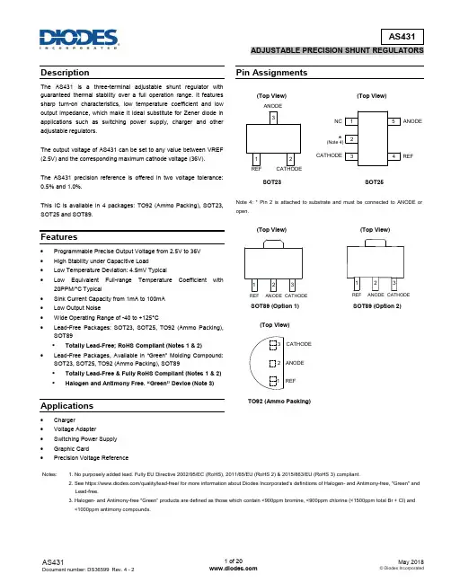
DescriptionThe AS431 is a three-terminal adjustable shunt regulator with guaranteed thermal stability over a full operation range. It features sharp turn-on characteristics, low temperature coefficient and low output impedance, which make it ideal substitute for Zener diode in applications such as switching power supply, charger and other adjustable regulators.The output voltage of AS431 can be set to any value between VREF (2.5V) and the corresponding maximum cathode voltage (36V).The AS431 precision reference is offered in two voltage tolerance: 0.5% and 1.0%.This IC is available in 4 packages: TO92 (Ammo Packing), SOT23, SOT25 and SOT89.Features∙ Programmable Precise Output Voltage from 2.5V to 36V ∙ High Stability under Capacitive Load ∙ Low Temperature Deviation: 4.5mV Typical∙ Low Equivalent Full-range Temperature Coefficient with 20PPM/°C Typical ∙ Sink Current Capacity from 1mA to 100mA ∙ Low Output Noise∙ Wide Operating Range of -40 to +125°C∙Lead-Free Packages: SOT23, SOT25, TO92 (Ammo Packing), SOT89 ▪ Totally Lead-Free; RoHS Compliant (Notes 1 & 2) ∙Lead-Free Packages, Available in “Green” Molding Compound: SOT23, SOT25, TO92 (Ammo Packing), SOT89 ▪ Totally Lead-Free & Fully RoHS Compliant (Notes 1 & 2) ▪ Halogen and Antimony Free. “Green” Device (Note 3)Applications∙ Charger ∙ Voltage Adapter ∙ Switching Power Supply ∙ Graphic Card∙Precision Voltage ReferencePin Assignments(Top View) (Top View)SOT23 SOT25Note 4: * Pin 2 is attached to substrate and must be connected to ANODE or open.(Top View) (Top View)SOT89 (Option 1) SOT89 (Option 2)(Top View)TO92 (Ammo Packing)Notes: 1. No purposely added lead. Fully EU Directive 2002/95/EC (RoHS), 2011/65/EU (RoHS 2) & 2015/863/EU (RoHS 3) compliant.2. See https:///quality/lead-free/ for more inf ormation about Diodes Incorporated’s definitions of Halogen - and Antimony-free, "Green" and Lead-free.3. Halogen- and Antimony-free "Green” products are defined as those which contain <900ppm bromine, <900ppm chlorine (<1500ppm tot al Br + Cl) and<1000ppm antimony compounds.ANODECATHODEREF321123REFCATHODEANODE 123REFCATHODEANODE REFCATHODE ANODE12345NC (Note 4)*REF CATHODEANODE 123Typical Applications CircuitShunt RegulatorHigh Current Shunt RegulatorCurrent Source or Current LimitTypical Applications Circuit (Cont.)Precision 5V 1A RegulatorPWM Converter with ReferenceFunctional Block DiagramAbsolute Maximum Ratings (Note 5)Symbol Parameter Rating Unit V KA Cathode Voltage 40 VI KA Cathode Current Range (Continuous) -100 to 150 mAI REF Reference Input Current Range 10 mAP D Power Dissipation Z, R Package 770mW N, K Package 370T J Junction Temperature +150 °CT STG Storage Temperature Range -65 to +150 °CESD ESD (Human Body Model) 2000 V functional operation of the device at these or any other conditions beyond those indicated under “Recommended Operating Conditions” is not implied.Exposure to “Absolute Maximum Ratings” fo r extended periods may affect device reliability.Recommended Operating ConditionsSymbol Parameter Min Max Unit V KA Cathode Voltage V REF36 VI KA Cathode Current 1.0 100 mAT A Operating Ambient Temperature Range -40 +125 °CElectrical Characteristics (Operating Conditions: T A = +25°C, unless otherwise specified.)Electrical Characteristics (Cont.)Test Circuit 4 for V KA = V REFTest Circuit 5 for V KA > V REFTest Circuit 6 for I OFFPerformance CharacteristicsReference Voltage vs. Ambient Temperature Reference Current vs. Ambient TemperatureCathode Current vs. Cathode Voltage Cathode Current vs. Cathode VoltageOff-State Cathode Current Ratio of Delta Reference Voltage to thevs. Ambient Temperature Ratio of Delta Cathode VoltageR e f e r e n c e V o l t a g e (V )Ambient Temperature (o C)R e f e r e n c e C u r r e n t (μA )Ambient Temperature (0C)C a t h o d e C ur r e n t (m A )Cathode Voltage (V)C a t h o d e C u r r e n t (μA )Cathode Voltage (V)O f f -S t a t e C a t h o d e C u r r e n t (μA )Ambient Temperature (oC)∆V R E F / ∆V K A (m V /V )Ambient Temperature (oC)Performance Characteristics (Cont.)Small Signal Voltage Gain vs. FrequencyReference Impedance vs. FrequencyStability Boundary Conditions vs. Load CapacitanceV o l t a g e G a i n (d B )Small Signal Frequency (Hz)R e f e r e n c e I m p e d a n c e (Ω)Frequency (Hz)C a t h o d e C u r r e n t (m A )Load Capacitance (μF)Performance Characteristics (Cont.)Pulse Response of Input and Output VoltageInputandOutputVoltage(V)Time ( S)Ordering InformationA : 0.5% Z : TO92(Ammo Packing)N : SOT23TR : Tape & Reel orAmmoG1 : RoHS Compliantand GreenB : 1.0%K : SOT25R : SOT89E1 : RoHS CompliantPbLead-Free PbLead-FreePbLead-FreePbLead-FreePbLead-FreePbLead-FreePbLead-FreePbLead-FreeOrdering Information (Cont.)Notes: 6. All variants with TO92 package in Bulk packing (AS431AZ-E1, AS431BZ-E1,AS431AZ-G1 and AS431BZ-G1) are End of Life, recommendedalternatives are the variants with the same package in Ammo packing.NRND: Not Recommended for New Design.7. For packaging details, go to our website at: https:///design/support/packaging/diodes-packaging/.Marking Information(1) TO92 (Ammo Packing)(Front View)First and Second Lines: Logo and Marking ID (See Ordering Information) Third Line: Date Code Y: YearWW: Work Week of Molding A: Assembly House Code XX: Internal CodeAS431 XZ-XX YWWAXX PbLead-FreePbLead-FreeMarking Information (Cont.)(2) SOT23(Top View)(3) SOT89 (Top View)(4) SOT25(Top View)321XXX: LogoXXX: Marking ID (See Ordering Information)First Line: Logo and Marking ID (See Ordering Information) Second Line: Date Code Y: YearWW: Work Week of Molding A: Assembly House Code XX: Internal Code: LogoXXX: Marking ID (See Ordering Information)XXX23XXXX YWWAXX 1 XXXXYWWAXX231Package Outline Dimensions (All dimensions in mm(inch).)(1) Package Type: TO92 (Ammo Packing)Ty pPackage Outline Dimensions (Cont. All dimensions in mm(inch).)(2) Package Type: SOT23(3) Package Type: SOT251.300(0.051)(4) Package Type: SOT89Option 1Option 2Suggested Pad Layout(1) Package Type: SOT23Grid placement courtyardSuggested Pad Layout (Cont.)(2) Package Type: SOT25Suggested Pad Layout (Cont.)(3) Package Type: SOT89Z。
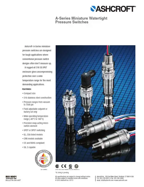
FEATURES:•Compact size•316 stainless steel construction •Pressure ranges from vacuum to 7500 psi•Field adjustable setpoint or factory set only•Wide operating temperature range (-40°C to 100°C)•Precision snap-acting micro switch element •SPDT or DPDT switching •UL,CSA listed models •CRN models available •CE and ROHS compliant •SIL 3 capableAshcroft A-Series miniaturepressure switches are designed for tough applications where conventional pressure switch designs often don’t measure up. A rugged all 316 SS IP67enclosure gives uncompromising protection over a wide temperature range for the most demanding applications.*UL listing is pendingSIL 3 CAPABLEBULLETIN SW-AWTAshcroft Inc., 250 East Main Street, Stratford, CT 06614 USA Tel: 203-378-8281 • Fax: 203-385-0408email:*****************•All specifications are subject to change without notice. All sales subject to standard terms and conditions.© 2013 Ashcroft Inc. 07/13A-Series Miniature Watertight Pressure SwitchesLOOK FOR THESE MARKS ON OUR PRODUCTSCutaway view of switch assembly with welded SS diaphragmMICRO-SWITCHCIRCUIT BOARD ASSEMBLYDIAPHRAGMSPRING GUIDEA rugged 316 SS enclosure gives uncompro-mising protection. Materials of construction have been selected for long life. Precision snap acting micro switches are featured and fully encased to prevent moisture from corroding switch contacts. The switch, depending on range, is either an all welded 316 stainless steel diaphragm sealedpiston design or a direct acting piston design sealed with a Buna-N or Viton O-ring.Applications include:Offshore oil rigs-where stainless steel construction and small size is desirable.Chemical and petrochemical plants-where small size and corrosion resistance construction is important.Pulp and paper mills-where corrosion resistance and sealed contacts extend life.Special equipment such as autoclaves and sterilizers-where special connections are needed.Rail and heavy vehicle hydraulic and pneumatic braking applications-where small size is an advantage and long life is required.Other special machinery and equipment applications-where small size and high performance is a must.Cutaway view of switchassembly with SS pistonMICRO-SWITCHCIRCUIT BOARD ASSEMBLYO-RINGSPRING GUIDEᕢSELECTION GUIDEBefore selecting a switch model the f ollowing should be considered:Actuator:The actuator responds to changes in pressure and operates the micro switch element in response to these changes. The actuator is normallyexposed to the process media and must be chem-ically compatible with it. There are three types of actuators available for the A-Series switches –all welded 316 SS diaphragm sealed piston; 316 SS piston with Viton O-ring seal; and 316 SS piston with Buna-N O-ring seal. The 316 SS diaphragm is available in ranges from –15/15 psi to 200 psi. The 316 SS piston is available in ranges from 100 psi to 7,500 psi. Switches offered in 100 psi and 200 psi can be ordered with either the piston or diaphragm design. The piston design will have a longermechanical life, while the diaphragm design has a better operating temperature.The piston design is more reliable than a diaphragm design when subjected to frequent large pressure excursions, pressure surges and spikes associated with typical hydraulic applica-tions. Piston designs are typically used when the switch is used as low pressure alarm or cutoff where the normal working pressure is above the nominal range of the switch.The Switching Function:Most applications for alarm, shutdown and interlock are satisfied by the standardA-Series switches which feature single setpoint fixed deadband. For pump, compressor and other control applications, the dead-band becomes a very important c onsideration and may requireincreasing the range of the switch to increase thedeadband. Please consult your Ashcroft represen-tative for assistance with special applications.The Micro Switch Element:The micro switch element must be chosen to meet the electrical load requirement to be switched.The switches are offered as either SPDT (single pole double throw) or DPDT (double pole double throw). The DPDT switch is made up of two SPDT switches which are adjusted to work together by Ashcroft’s patent pending Circuit Board Rotation Design. DPDT switching is not available on diaphragm designs below 100 psi, with Spade terminals or the Micro DIN connector.Understanding Setpoints and Reset Points:Pressure switches can be set to switch on either increasing (rising) or decreasing pressures. Since the switches have both Normally Open (NO) con-tacts and Normally Closed (NC) contacts you can wire the switch to open or close for either an increasing or decreasing pressure. To be consis-tent in setting the switches Ashcroft defines the setpoints as follows. For an increasing setpoint,the pressure is increased from 0 psi to the set point and then decreased to the reset point. For a decreasing setpoint, the pressure is increased to full range and then decreased to the setpoint and then increased to the resetpoint.Custom Applications:The A-series switch is designed to allow custom process connections and electrical terminations. Please consult your Ashcroft representative for assistance with custom applications.ᕣA-Series Miniature Watertight Pressure SwitchesAVAILABLE PRESSURE CONNECTIONSAVAILABLE ELECTRICAL CONNECTIONS1/8 or1/4 MALE NPT18 AWG WIRE LEADS1/2 NPT CONDUIT CONNECTORWITH 18 AWG WIRE LEADSSPADE TERMINAL 4-0.187 MALE TERMINALSHIRSCHMANNMICRO-DIN CONNECTOR43650 FORM CDPDT 18 AWG LEADS1/8 or1/4FEMALE NPT7/16 ˝-20 SAE3/4 ˝, 1.5˝ or 2.0˝SANITARYVCR or VCOᕤRANGESETPOINT REPEATABILITYSETPOINT ADJUSTABILITYDEADBAND (DB)psi bar kg/cm kPa psi bar, kg/cm kPa psi bar, kg/cm kpa psi bar, kg/cm kPa–15/15–1/1–100/100±0.6±.04±4–15/15–1/1–100/1001-5.07-.357-35 302200±0.6±.04±46-30.4-24-2001-5.07-.357-35604400±1.2±.08±88-60.6-460-4002-10.14-.7014-701007700±2±.14±1410-100.7-770-7003-15.2-1.020-100200141400±4±.28±2820-200 1.4-1.4140-14003-30.2-2.020-2001007700±2±.14±1420-100 1.4-7140-7003-15.2-1.020-100200141400±4±.28±2840-200 2.8-1.4280-14003-30.2-2.020-200500353500±10±.70±7050-500 3.5-35350-350020-100 1.4-7.0140-7001000707000±20±1.40±140100-10007-70700-700025-150 1.7-10170-1000200014014000±40±2.8±280200-200014-1401400-140030-3002-20200-2000500035035000±100±7.0±700500-500035-3503500-3500075-7505-50500-5000750050050000±150±10±1000750-750050-5005000-50000110-11007.5-75750-7500ELECTRICMATERIAL & TEMPERATUREPROOF PRESSURESwitch Electric Actuator MaterialTemperature Ranges (Material)Codeon LabelSealRangelisted in psipsibar kg/cm 2kPa1P, 2P 3A 125Vac; 2A, 30Vdc SSS –40-100C up to 200(S)10007070001H, 2H 5A 125/250Vac; 5A, 28Vdc B (Ranges 100#, 200#)SS, BUNA –28-100C 100-200 (B, V)200014014001G, 2G 0.1A 125Vac; 0.1A 30Vdc B (Ranges 500# to 7500#)SS, BUNA –40-100C500-2000 (B, V)8000550550001L, 2L1A 125Vac; 1A 28VdcVSS, BUNA–20-100C 5000-7500 (B, V)150001000100000SPECIFICATIONS:Setpoint:Factory set or field adjustable Setpointrepeatability:±2% of range(Additional setpoint shift of ±2% of range per 40°F from initial setpoint set at 70°F typical)Vibration:Passed MIL-STD-202G Shock:75G’s 10 milliseconds 3 axis Piston:Stainless steel with Viton or Buna-N O-ring Mechanical life piston design:>1,000,000 operations typical Diaphragm:316L SS Mechanical life diaphragm design:>400,000 operations typicalEnclosurematerial:316L SS Enclosure rating:NEMA 6, IP 67Pressure connection:1⁄8NPTF, 1⁄4NPTF, 1⁄4NPTM, 1⁄8NPTM, 7/16-20 SAE M, VCR, VCO, 3⁄4˝ Tri-Clamp , 1.5˝ Tri-Clover ,2.0˝ Tri-Clover , G 1⁄4B, G 1⁄4A Type E Stub endElectrical output:SPDT, or DPDT 5A or 3A 120VAC, 2A @ 30 VDC, gold contacts available Electrical termination:Wire leads, spade terminals or custom cables, 1⁄2NPT conduit c onnec-tion with wire leads, Micro DIN with and without mating connectorApprovals:CRN: OF 14836.5C, CSA: 2454057 (LR55528), UL: E34743, CE, ROHSD I A P H R A G MP I S T O N Tri-Clover is a registered trademark of Alfa Laval Tri-Clamp is a registered trademark of Ladish Co.ᕥRanges (Material) listed in psipsibar, kg/cm 2kPaUp to 200 (S)>9500>655>65,500100-200 (B,V)>10,000>700>70,000500-2000 (B,V)>30,000>2100>210,0005000-7500 (B,V)>50,000>3500>350,000CONFIGURATIONMAX. WORKING PRESSURE “MWP”PROOF PRESSURE “PROOF”RANGES (psi)w/SEALpsibar, kg/cm2kPa MPapsibar kg/cm 2kPaup to 200S 800555500 5.51000707000100-200 B or V 2000140140014200014014000500-2000 B or V 500035035000358000550550005000-7500B or V100007007000070150001000100000A-Series Miniature Watertight Pressure SwitchesAPS – Pressure switch, single setpoint, fixed dead-band, factory set, not field adjustableAPA – Pressure switch, single setpoint, fixed dead-band, field adjustableN4– Watertight 316 SS bodyCode1Single Switch –SPDT2Dual Switch –DPDT (not available with “S”actuator with <100 psi range)CodeDescription011⁄8NPT Male 021⁄4NPT Male 031⁄8NPT Female*12G 1⁄4 A (Type E Stud End)13G 1⁄4 B 251⁄4NPT Female*057⁄16-20 SAE Male 06VCR Fixed*07VCO Fixed*750.75˝ Tri-Clamp connection (includes 3A Approval)†15 1.5˝ Tri-Clover connection (includes 3A Approval)†202.0˝ Tri-Clover connection (includes 3A Approval)†5 characters maximum representing setpoint of the switch in the same units as the range of the switch. For setpoints in Vacuum specify as “– ”pressure.CodeDescriptionXC4Individual certified calibration chart XFP Fungus proofingXMQ Positive Material Identification (75, 15 & 20 process conn. only)XNC 2 wire leads with ground wire –wired for normally closed operationXNO 2 wire leads with ground wire –wired for normally open operation XNH Stainless Steel Tag XNN Paper TagX6BCleaned for Oxygen serviceCodeB 316 SS piston & Buna O-ring, ranges ≥100 psi V 316 SS piston & Viton O-ring, ranges ≥100 psi S 316 SS welded Diaphragm, ranges ≤200 psiCode012C‡½ NPT male conduit connection with18 AWG ˜wires 12˝ length000H Micro DIN Connector – Watertight DIN 43650**FORM C cable socket without mating connector Not available with DPDT switching00MH Micro DIN Connector – Watertight DIN 43650**FORM C cable socket with mating connector Not available with DPDT switching012L‡Wire leads, 3-18 AWG PVC insulated wires12˝ length000N Nonstandard, customer specified see# variation000T Spade terminals, 4 - 0.187˝ male spadeNot available with DPDT switchingActuatorpsiBarkPaKg/cm 2S –15/15#–1/1BR –100/100KP –1/1KSC S 30#2BR 200KP 2KSC S 60#4BR 400KP 4KSC B, S, V 100#7BR 700KP 7KSC B, S, V 200#14BR 1400KP 14KSC B, V 500#35BR 3500KP 35KSC B, V 1000#70BR 7000KP 70KSC B, V 2000#140BR 14000KP 140KSC B, V 5000#350BR 35000KP 350KSC `B, V 7500#500BR 50000KP 500KSCCodeG Gold Contact –0.1 A @ 125 Vac, 0.1 A @ 30 VdcHHigher Current –5A @ 125/250 Vac,5A @ 28 Vdc resistive, 3A @ 28 Vdc inductiveLHigher CurrentGold Contacts –1A @125 Vac,1A @ 28 Vdc resistive, 0.5A @ 28 Vdc InductivePGeneral Purpose –3A @ 125 Vac,2A @30 VdcCodeR Rising Pressure (Increasing Pressure, Decreasing Vacuum)D Decreasing Pressure, (Increasing Vacuum)A-Series Part Number:APSN41H012CS02 30# - 15 R - X6B1. Function:2. Enclosure:3. Micro Switch:4. Electrical Connection:5. Actuator Seal:6. Pressure Connection:7. Pressure Range:8. Setpoint:9. Setpoint Direction:10. Options:HOW TO ORDER:PRESSURE CONNECTION NOTES* Available with “S” activator only.†Ranges ≤ 500 psi .SETPOINT NOTESIf no setpoint is required on an APA switch use either “NSR” or “NSD.” If direction is not known use “NSR” as the default.OPTIONS NOTE SThe X character will only appear before the first option, additional options will just be the two characters. Example: XC4NC6BIf the switch is mounted to a diaphragm seal other than (75, 15, 20 connection) the seal fill fluid is also listed as an X option.**OOOH & OOMH connection are not UL listed. They are CSA listed.ᕦ‡First three digits represent the length of the wire leads in inches. 012, 024, 048 & 072 are standard available lengths. Consult factory for custom length availability.ADDITIONAL SWITCH TERMINOLOGYAccuracy –(See repeatability) Accuracy normally refers to conformity of an indicated value to an accepted standard value. There is no indication in switch products; thus, instead, the term repeatability is used as the key performance measure. Ashcroft A-Series switch accuracy is 2% of nominal range.Automatic Reset Switch –Switch which returns to normal state when actuating variable Pressure is reduced.Adjustable or Operating Range –That part of the nominal range over which the switch setpoint may be adjusted. Normally about 10% to 100% of the nominal range for A-Series pressure switches.Burst Pressure –The maximum pressure that may be applied to a pressure switch without caus-ing leakage or rupture. This is approximately 16X of nominal range for A-Series switches. Diaphragm switches subjected to pressures above the nominal range can be permanently damaged.Deadband –The difference between the setpoint and the resetpoint, normally expressed in units of the actuating variable. Sometimes referred to as differential.Fixed Deadband –The difference between the setpoint and the resetpoint of a pressure switch. It further signifies that this deadband is a fixed func-tion of the pressure switch and not adjustable.National Electrical Manufacturers Association (NEMA) –This group has defined several cate-gories of enclosures, usually referred to as “types.”Further, they designate certain features and capa-bilities each type must include.NEMA 6 –Enclosures constructed for either indoor or outdoor use to provide a degree of protection to personnel against access to hazardous parts; to provide a degree of protection of the equipment inside the enclosure against ingress of solid foreign objects (falling dirt); to provide a degree of protec-tion with respect to harmful effects on the equip-ment due to the ingress of water (hose directed water and the entry of water during occasional temporary submersion at a limited depth); and that will be undamaged by the external formation of ice on the enclosure.Normal Switch Position –Contact position before actuating pressure (or variable) is applied.Normally closed contacts open when the switch is actuated. Normally open contacts close when the switch is actuated.Normally Closed –Refers to switch contacts that are closed in the normal switch state or position (unactuated). A pressure change opens the contacts.Normally Open Switch –Refers to the contacts that are open in the normal switch state or position (unactuated). A pressure change closes the contacts.Overpressure Rating(s) –A nonspecific term that could refer to either burst or proof pressure, or both.Proof Pressure –The maximum pressure which may be applied without causing damage. This is determined under strict laboratory conditions including controlled rate of change and tempera-ture: This value is for reference only. Consult fac-tory for applications where switch must operate at pressures above nominal range or reference tem-perature (70°F).Repeatability (Accuracy) –The closeness of agreement among a number of consecutive mea-surements of the output setpoint for the samevalue of the input under the same operating condi-tions, approaching from the same direction, for full-range traverses. Ashcroft A-series switch repeata-bility is 2% of nominal range.Note:It is usually measured as non-repeatability and expressed as repeatability in percent of span or nominal range. It does not include hysteresis or deadband.Resetpoint –The resetpoint is the Pressure value where the electrical switch contacts will return to their original or normal position after the switch has activated.Setpoint –The setpoint is the Pressure value at which the electrical circuit of a switch will change state or actuate. It should be specified either on increase or decrease of that variable.Single Pole Double Throw (SPDT) Switching Element –A SPDT switching element has one normally open, one normally closed, and one com-mon terminal. The switch can be wired with the cir-cuit either normally open (N/O) or normally closed (N/C). SPDT is standard with A-series switches.Double Pole Double Throw (DPDT) Switching Element –Two SPDT switching elements both set to actuate or de-actuate at the same set or reset-point. Each switch one has one normally open,one normally closed, and one common terminal.The switches are independent of each other and can be wired to two independent circuits. The two circuits can either normally open (N/O) or normally closed (N/C).Snap Action –In switch terminology, snap action generally refers to the action of contacts in the switch element. These contacts open and close quickly and snap closed with sufficient pressure to firmly establish an electrical circuit. The term dis-tinguishes products from mercury bottle types that were subject to vibration problems.ᕧA-Series Miniature Watertight Pressure SwitchesCOVERROTATE LEFT <––––TO INCREASE SET POINT ROTATE RIGHT ––––>TO DECREASE SET POINT .095 OR SMALLER TOOL REQUIRED TO ROTATE NUT SLIDE COVER DOWN TO ACCESS SETPOINT ADJUSTMENT. SLIDE COVER UP TO CLOSE AND SEAL ADJUSTMENTFIELD ADJUSTABLE FACTORY SET.095 OR SMALLER TOOL REQUIRED TO ROTATE NUTSLIDE COVER DOWN TO ACCESS SETPOINT ADJUSTMENT. SLIDE COVER UP TO CLOSE AND SEAL ADJUSTMENTFIELD ADJUSTABLEDIMENSIONS:CodeDescriptionDim. CDim. D011/8 NPT Male 0.450.41021/4 NPT Male 0.560.54031/8 NPT Female 0.750.65041/4 NPT Female 0.920.75057/16-20SAE 0.560.4406VCR Fixed Male 0.580.5607VCO Fixed Male 0.470.5615 1.5˝ Tri-Clamp Seal 1.23 1.9920 2.0˝ Tri-Clamp Seal 1.23 2.49753/4˝ Fractional Seal1.100.96DescriptionDim. B1H, 2H, 1L, 2L 1.031P, 2P, 1G, 2G 0.90DescriptionDim. AAPS (Factory Set) 1.06APA (Field Adjustable)1.64MICRO DIN (000H) NO CONN.(001H) WITH CONN.SPADE TERMINALS(000T)1.07.60.591.37.34.41MATINGCONNECTOR1/ NPT CONDUIT (XXXC)XXX = WIRE LENGTH (in.)WIRE LEAD (XXXL) CONNECTION WITH DUAL SWITCH SHOWNXXX = WIRE LENTH (in.)ØSIL 3 CAPABLEBULLETIN SW-AWTAshcroft Inc., 250 East Main Street, Stratford, CT 06614 USA Tel: 203-378-8281 • Fax: 203-385-0408email:*****************•All specifications are subject to change without notice. All sales subject to standard terms and conditions. © 2013 Ashcroft Inc. 7/13LOOK FOR THESE MARKS ON OUR PRODUCTS。
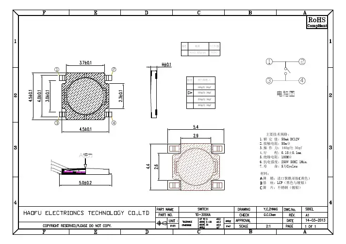
1.General specification 基本说明1.1Scope 范围This specification covers the requirements for single key switches which have no keytop(TACT SWITCHES:MECHANICAL CONTACT ). 此规范含盖单推柄和无推柄的轻触开关要求。
1.2Operating Temperature Range 使用温度范围-55 to 125 ℃(normal humidity, normal press).正常湿度,标准压力1.3Storage Temperature Rang 保存温度范围-25 to 85 ℃(normal humidity, normal press).1.4Test Conditions 测试条件Tests and measurements shall be made in the following standard clnditions unless otherwise specified:测试和计量按下列标准条件除非特殊说明Normal temperature (temperature 5 to 35℃) 标准温度Normal humidity (relative humidity 45 to 85%) 正常湿气Normal pressure (pressure860 to 1060 mbars ) 标准压力In case any question arises from the judgement made, tests shall be conducted in the following conditions:Temperature (20±2℃) 温度Relative humidity (65±5%) 相对湿度Pressure (860 to 1060 mbars) 压力2. APPEARNCE, STYLE, AND DIMENSIONS 外形,类型和尺寸2.1Appearance 外形There shall be no defects that affect the serviceability of the product 外形必须无缺陷才不影响产品适用性2.2 Style and Dimensions 类型和尺寸Shall conform to the assembly drawings. 符合装配图3.TYPE OF ACTUATION 动作类型Tactile feedback 轻触返回4. CONTACT ARRANGEMENT 1 poles 1 throws 接触形式1接点1 回路(Details of contact arrangement are given in the assembly drawings).细接点形式在装配图中5. MAXOMUM RATINGS DC 12 V 50 mA 最大额定值APPD CHKD DSGDTD-309XA1/7ZONE SYMB DATE APPD CHKD DSGD6.2Mechanical机械特性Item 项目Test Condition试验条件Requirements规格6.2.1. Actuating Force 动作力Placing the switch such that the direction of switchoperation is vertical and then gradually increasing theload applied to the center of the stem, the maximum loadrequired for the stem to come to a stop shall bemeasured.开关的动作方向为垂直放置开关向推柄中心逐渐增加负荷直到推柄停止时所测量的最大负荷160±30gf6.2.2. Travel 行程Place the switch such that the direction of switch operation isvertical and then apply a static load twice the actuating force tothe center of the stem, the travel distance for the stem to come toa stop shall be measured.开关的动作方向为垂直放置开关,并以双倍动作力的静负荷作用推柄中心,测量推柄从开始到停止的行程距离0.15±0.1mm6.2.3.Return Force 返回力The sample switch is installed such that the direction ofswitch operation is vertical and, upon depression of thestem in its center the whole travel distance ,the force ofthe stem to return to its free position shall be measured.开关的动作方向垂直放置开关,在已有行程的推柄中心向上减小压力,推柄回到自由位置时所测量到的力40gf min6.2.4. Stop Strength 静止强度Placing the switch such that the direction of switchoperation is vertical, a static load of 3 kgf shall beapplied in the direction of stem operation for a period of60 seconds.开关的动作方向为垂直放置开关,在推柄动作方向施加3 KG的静负荷,60秒时间There shall be no sign ofdamage mechanically andelectrically无机械的和电气的损伤迹象6.2.5. Stem Strength 推柄的强度Placing the switch such that the direction of switchoperation is vertical, the maximum force to withstand apull applied oppsite to the direction of stem operationshall be measured.开关的动作方向为垂直放置开关从推柄动作方向反方向施加拉力所测量到的最大承受力3 kgfAPPD CHKD DSGDTD-309XA2/7ZONE SYMB DATE APPD CHKD DSGDTACT SWITCH SPECIFICATION( 轻触开关说明书)6.PERFORMANCE 性能6.1 Electrical 电气Item 项目Test Condition试验条件Requirements 要求6.1.1.Contact Resistance 接触电阻Applying a static load twice the actuating force to thecenter of the stem, measurements shall be made witha 1 kHz small-currentcontact resistance meter.用两倍的动作力作静负载施加于按钮的中心,并用1 千赫小电流接触电阻仪测量100 mΩmax.6.1.2. Insulation Resistance绝缘电阻Measurements shall be made following application ofDC 100 V potintial across terminals and acrossterminals and frame for one minute.在端子之间,端子与外壳之间施加DC100V,一分种100 MΩmin6.1.3. Dielectric Witstanding voltage电气耐压AC250V (50Hz or 60Hz) shall be applied acrossterminals and across terminals and frame for oneminute.在端子与端子之间,端子与外壳之间施加AC250V(50Hz or60Hz)There shall be mo breakdown没有击穿6.1.4. Bounce 抖动Lightly striking the center of the stem at a rateencountered in normal use ( 3 to 4 operations persec ), Bounce shall betested at “ON” and “OFF”在正常使用中(以每秒3-4 次周期)轻轻地在手柄中心加力,在通与断瞬间测试抖动。
MICRO SWITCH™ Basic SwitchesV15W Water-tight Miniature Switches• •BZ Premium Large Switches• Accepted as the world-wide standard snap-action switch • Designed for 100K operations at full load or 10M for mechanical life• Current ratings from 10 A to 25 A •UL/CSA, CE, ENEC approvalsV7 Series Premium Switches• Delivers long-term reliability with a wide variety of electri-cal currents• Designed for 100K operations at full load or 10M for mechanical life• Current ratings from 0.1 A to 26 A •UL, cUL, ENEC, CQC approvalsMICRO SWITCH™ Limit SwitchesHDLS Series Heavy-Duty Switches• Industry-leading breadth-of-product offering:Standard, harsh-duty epoxy sealed, or stainless steel • NEMA 1, 3, 4, 4X, 6, 6P, 12, 13 & IP65/66/67 sealing • Enhanced mechanical life (50 million actuation cycles)• Zinc head and body: phosphate treated & epoxy coated • UL, CSA, CE, and CCC approvals for global useGLS Series Global Switches• Meet EN50041 & EN50047, and IEC electrical standards • Direct-opening, normally closed contacts (except wobbleactuators)• Metal or plastic housings•Dual bearing design on side rotary reduces side loading • UL, CSA, CE, and CCC approvals for global useHazardous Location Switches• Will withstand pressure of internal explosion • Weather-proof, water-tight, and dust-tight • Indoor and outdoor versions•Smaller sizes, lower cost options, and analog outputs available• UL, CSA, ATEX, and IEC Ex certified productsSafety Switches• •• •Heavy-Duty Pressure Sensors & TransducersPX2 Series Heavy-Duty Transducers• Piezoresistive sensing technology with ASIC signal condi-tioning in a stainless steel housing •Industry-leading TEB of ±2%• Over 15,000 standard configurations• Environmentally tough; withstands shock & vibration •IP65 or IP69K, depending on connectorMLH Series All-Metal Transducers• ASIC technology combined with a media isolated, metal diaphragm design• All metal wetted parts with no internal elastomeric seals • Six standard output options • Input reverse voltage protection• UL component recognition for USA/CanadaSPT Series Stainless Steel Transducers• Designed for media that will not adversely attack 316L stainless steel• 0 psi to 3 psi, 0 psi to 5000 psi• NEMA 4 design in a rugged, stainless steel housing • Absolute, gage, sealed gage, vacuum gage pressures • Three standard output options13mm/19mm Series Stainless Steel Sensors• Rugged, isolated stainless steel package • Small package size• Reliable semiconductor technology• Compensated and uncompensated options • Absolute and gage pressures•Vacuum compatible, isolated sensors availablePressure SwitchesHP , HE, LP , and LE Series• Gauge pressure devices available with either SPST -NO, SPST -NC, or SPDT circuitry• Factory set or field adjustable options• Hysteresis option (HP Series and LP Series only)• Variety of pressure ports and electrical terminations • IP67 sealing; UL508 pending, CE approvalsIndustrial Product Line CardLimitless™ Wireless Solutions00XXXX-1-EN IL50 GLO April 2014Sensing and Control Honeywell1985 Douglas Drive North Golden Valley, MN 55422 Find Out MoreTo learn more about Honeywell’sindustrial solutions, contact a Honeywell representative today at 1-800-537-6945 or visit MICRO SWITCH™ Operator ControlsNT Series Commercial-Grade Switches• Quality construction includes a seal between the togglelever and bushing, and between the cover and case • 1-, 2-, and 4-pole options• 2- or 3-position maintained and momentary action • NEMA 3, 3R, 4, 13 and IP67/68 environmental sealing • UL recognized, CSA certified, and CE certifiedPush-Pull Switches• Sliding contact switch incorporating two circuits with multiple combinations• Positive disconnect suitable for e-stop • Momentary push version available• Excellent vibration and shock resistance • UL, CE certifiedHour Meters• • • • • •Thermal SolutionsCommercial Thermostats• Half-inch, snap-action, bi-metallic, SPST non-hermetic • Automatic and manual reset options • Phenolic or ceramic housings• Wide variety of mounting brackets and terminals • Operating temp. range up to 260 °C [500 °F]•UL, CSA, and other international agency approvalsThermistors• Can be used as both a temperature monitor and control • Available in a wide range of resistance values• Variety of packages and styles from leaded devices to surface-mount versions • Tolerances as low as ±1 %• Extremely stable over lifePotentiometersBoard Mount SolutionsTruStability ® Series Pressure Sensors Basic Series Pressure Sensors Digital Hall-effect Sensor ICsHumidIcon™ Series Humidity Sensors• • ® Series)• • Digital output-type relative humidity (RH) and temperature sensors combined in the same package with accuracy up to ±1.7 %RH (HumidIcon™ Series)Packaged Temperature Probes• Operate with enhanced sensitivity, reliability, and stability under diverse conditions of shock, vibration, & corrosion • On-board signal conditioning circuitry available • Allows for monitoring of harsh gaseous and liquid environments• Wide selection of housings, resistances, & terminationsSMART Position SensorsHoneywell Zephyr™ Series• Total Error Band as low as ±0.25 %FSS• Standard flow ranges from ±50 SCCM to ±750 SCCM • Full calibration and temperature compensation•Customizable flow ranges and configurable package styles• Digital or analog interface。
Switches and Pilot Devices Selection Guide A-21A-19A-21A-19A-25A-25Illuminated Pushbuttons:• Momentary • Maintained • Pilot Lights Non-IlluminatedPushbuttons:• Momentary• MaintainedOversize LensIlluminatedPushbuttons:• Momentary• MaintainedOversize Button SelectorSwitches:• 2 or 3-Position• Maintained orSpring ReturnKeylockSwitches:• 2 or 3-Position• Maintained orSpring Return• Key removableoptionsRound: Ø 0.702" (18mm)Bezel Shape:UL Recognized File No. E55996CSA Certified File No. LR48366Switches and Pilot Devices General InformationSwitches and Pilot Devices General InformationMiniature Switches and Pilot DevicesA6 Series: 5/8" (16mm)IP65 Waterproof/Oiltight/Corrosion Resistant 5V AC/DC, 1mA (subject to operating conditions)(approx. 50G) Operating extremes: 200m/sec 2 (approx. 20G)100,000 operations minimum (at full rated load)Selector/Keylock: 250,000 operations mimimumSwitch Unit: 2,000VAC, 1 min. between live/dead part and terminals of different poles; CSA Certified File No. LR21451UL Recognized File No.E55996Miniature Switches and Pilot Devices A6 Series: 5/8" (16mm) Round 0.71" (18mm)Square 0.71" (18mm)Rectangular 0.71x 0.94"(18mm x 24mm)Round Ø 0.93" (23.5mm)Square 0.93" (23.5mm)(17.5 X 23.5mm)Round MushroomMiniature Switches and Pilot Devices A6 Series: 5/8" (16mm)Part NumberRound RectangularNon-Illuminated Pushbuttons AB6M-M100AB6Q-M100AB6H-M100AB6M-A100AB6Q-A100AB6H-A100AB6M-M200AB6Q-M200AB6H-M200AB6M-A200AB6Q-A200AB6H-A200AB6M-BK1-xAB6Q-BK1x AB6Q-BK1-Q x AB6Q-BK2-x AB6Q-BK2-Q xAB6H-BK1-x AB6Q-BK1-H x AB6H-BK2-x AB6Q-BK2-H x , specify button color code from table below.2. Buttons which are rated IP65 include a waterproof rubber gasket.Miniature Switches and Pilot Devices A6 Series: 5/8" (16mm) Round 0.71" (18mm) diameterSquare 0.71"x0.71" (18mmx18mm)Rectangular 0.71"x0.94" (18mmx24mm)Round Ø 0.93" (23.5mm) diameterSquare 0.93"x0.93" (23.5mmx23.5mm)Rectangular 0.69"x0.93" (17.5mmx23.5mm)Miniature Switches and Pilot Devices A6 Series: 5/8" (16mm)Part NumberSquare RectangularAL6 Illuminated Pushbuttons AL6Q-M100AL6H-M100AL6Q-A100AL6H-A100AL6Q-M200AL6H-M200AL6Q-A200AL6H-A200AL6M-LK2-M➁AL6Q-LK1-➁AL6Q-LK1-Q➁AL6Q-LK2-➁AL6Q-LK2-Q➁AL6H-LK1-➁AL6Q-LK1-H➁AL6H-LK2-➁AL6Q-LK2-H➁1. In place of ➁, specify lens color code from table below.2. Lenses which are rated IP65 include a waterproof rubber gasket.For accessories, see page A-26.Part Numbers: Replacement LED Lamps Lens/LED Color CodeCodeAppearanceGD (lenses)G (LED lamps)1.➁2.reverse polarity protection diode.Miniature Switches and Pilot Devices A6 Series: 5/8" (16mm) Round 0.71" (18mm)Square 0.71" (18mm)Rectangular 0.709 x 0.984" (18mm x 24mm)RectangularAL6 Pilot LightsAL6M-LK1-➁AL6M-LK3-➁AL6Q-LK1-➁AL6Q-LK3-➁AL6H-LK1-➁, specify lens color code from table below.2. Lenses which are rated IP65 include a waterproof rubber gasket.1.In place of ➁, specify LED color code.Round Selector Round Keylock Square Selector Square KeylockRectangular Selec-torspecify color code. A=Amber, W=White, G=Green, Y=Yellow, R=Red, S=Blue. LEDs include built-in current limiting resistor and reverse polarity protecction diode.(2.8mm)0.118"0.866"See (0.5mm to 6mm)Thickness0.118"(3mm)(0.5mm to 6mm)Thickness。
®S p e c i f i c at i o n S u b m i t ta lpageJob Name:Model Numbers:Maestro R Occupancy Sensor C •L R Dimmer Lutron R Maestro R occupancy sensor C•L R dimmersare lighting controls with passive infrared sensors that automatically control the lights in an area. These sensors detect heat from occupants moving within an area to determine when the space is occupied. The Maestro R occupancy sensor C•L R dimmer combines a Maestro R C•L R dimmer with an occupancy or vacancy sensor.Features• C ontrols CFL, LED, incandescent, and halogen load types *• P assive infrared motion detection with exclusive Lutron R XCT T Technology for fine motion detection • 180˚ sensor field-of-view • U p to 30 ft x 30 ft (9 m x 9 m) [900 ft 2 (81 m²)] major motion coverage and 20 ft x 20 ft (6 m x 6 m) [400 ft 2 (36 m²)] minor motion coverage • O ccupancy version can be set to auto-on/auto-off or manual-on/auto-off • V acancy version available to meet CA Title 24 requirements • A djustable timeout (1, 3, 5, 15, or 30 minutes) and high/low sensitivity adjustmentModels Available•A djustable settings for auto-on light level (occupied level): 100%, 50%, last light level, or locked preset light level • O ff warning fades lights to off over a period of 10 seconds • A dvanced Maestro R dimmer features available (locked preset, fade-to-on, and fade-to-off, etc.)• A ll models have single pole and multi-location capability • W orks with a single standard mechanical 3-way switch or up to 9 companion dimmers/switches (MA-R or MSC-AD) *** For a complete list of compatible DIMMABLE CFLs and LEDs please visit /dimcflled ** If using with standard mechanical 3-way switch, some rewiring and dimmer programming is required *** XX in model number represents color/finish code1SpecificationsRegulatory Approvals• U L Listed to U.S. and Canadian safety requirements • T itle 20/24 certified lighting control device– C omplies with Title 20 and Title 24 Section 119(Until Jan 1st, 2014)• T itle 20/24 certified lighting control device– C omplies with Title 20 and Title 24 Section 110.9 (After Jan 1st, 2014)Power• O perating voltage: 120 V~ 60 HzEnvironment• A mbient operating temperature: 32 °F to 104 °F (0 °C to 40 °C), 0%-90% humidity, non-condensing; indoor use onlyWarranty• 5 Year Limited WarrantyFor additional Warranty information, please visit:w /TechnicalDocumentLibrary/Sensor_ Warranty.pdfKey Design FeaturesDimmer• O n a single-tap, lights fade ON or OFF• O n a double-tap, lights go to full ON• W hen ON, press and hold to engage a long fade to OFF• L ight levels can be fine-tuned by pressing and holding the dimming rocker until the desired light level is reachedCustom Sensor SettingsTimeout Options• 1 Minute• 3 Minute• 5 Minutes (default)• 15 Minutes• 30 Minutes• Test Mode– S hort (less than 15-second) timeout for testingsensor coverage. After entering, device will exittest mode automatically after 5 minutes, orwhen any button is pressed.Sensitivity Options• High sensitivity (default)• Low sensitivityAuto-ON Options• Occupancy (default): Auto-ON / Auto-OFF– Occupancy Mode is also called “Auto-On: Enabled”• Vacancy *: Manual-ON / Auto-OFF– Vacancy Mode is also called “Auto-On: Disabled”* T here is a 15-second grace period that begins when the lights areautomatically turned off, during which the lights will automatically turnback on in response to motion. This grace period is provided as a safety and convenience feature in the event that the lights turn off while theroom is still occupied, so that the user does not need to manually turn the lights back on. After 15 seconds, the grace period expires and the lights must be manually turned on.• Ambient Light Detection (ALD): Lights turn on only if natural light in room is low– Smart—Ambient light threshold adjusts to theuser’s preference **** I f sensor turns on when there is enough natural light, or if sensor doesnot turn on when there is not enough natural light, press the large button within 5 seconds of entering the room. Over time, this interaction will“teach” the sensor your preferred setting.• Off While Occupied (OWO)– When the sensor dimmer is manually turned off,the sensor dimmer will not turn the lights back onautomatically while the room is occupied.– Once the room is vacated, the Auto-ON featurereturns to normal operation after the timeout period has expired.– This may be the preference in conference roomsor classrooms while viewing presentations. Thisfeature requires motion to keep the lights off.Occupied Level OptionsOccupied Level is the light level that the sensordimmer will turn ON to when motion is detected. • 100% (default)• 50%• Preset– While in preset mode, lights will automatically turnto the last level or to the “Locked Preset” level if a“Locked Preset” has been selected in AdvancedProgramming.2®S p e c i f i c at i o n S u b m i t ta l page Job Name:Model Numbers:®S p e c i f i c at i o n S u b m i t ta lpageJob Name:Model Numbers:Load Type and Capacity1 Dimmer Load T ype: designed for use with permanently installed lighting fixtures only. Do not install dimmers to control receptacles or motor-operated appliances. 2For mixed load types, see Mixed Load Type and Capacity section. 3For a complete list of approved Dimmable CFLs and LEDs, please visit /dimcflled. For questions call: 1.800.523.9466.Additional Information• F or Maestro R Occupancy sensing switch models, please see Lutron R P/N 369666 at .• L utron Technical Hotline: 1.800.523.9466.Mixed Load Type and CapacityDetermine allowable wattage (W) of dimmer by following the steps below. If multiple dimmers are to be installed adjacently in the same wallbox, derating is required.Derating Chart1. Determine total wattage of CFL/LED bulbs installed for dimmer control.2. D etermine total wattage of Incandescent/Halogen bulbs to be controlled by the dimmer.3.U se the Derating Chart to determine if your total wattages are within the allowable range of your configuration. 4. D erating Procedure (if necessary)I f multiple dimmers are installed adjacently in the same wallbox, heat fins MUST be removed between adjacent dimmers. This will permanently derate the dimmer, reducing its total allowable Incandescent/Halogen wattage.ExampleIncandescent/Halogen lighting.3®S p e c i f i c at i o n S u b m i t ta lpageJob Name:Model Numbers:Horizontal Beam Diagram5 ft (1.5 m)5 ft (1.5 m)010 ft (3 m)10 ft (3 m)15 ft (4.5 m)15 ft (4.5 m)20 ft (6 m)20 ft (6 m)25 ft (7.5 m)25 ft (7.5 m)30 ft (9 m)30 ft (9 m)Vertical Beam Diagram5 ft (1.5 m)010 ft (3 m)10 ft (3 m)15 ft (4.5 m)15 ft (4.5 m)20 ft (6 m)20 ft (6 m)25 ft (7.5 m)25 ft (7.5 m)30 ft (9 m)30 ft (9 m)4 ft (1.2 m)NEMA WD7 Test Grid Coverage (High Sensitivity Setting)5 ft (1.5 m)5 ft (1.5 m)10 ft (3 m)10 ft (3 m)15 ft (4.5 m)15 ft (4.5 m)5 ft (1.5 m)Major motion coverage: 900 ft ( (81 m ()Minor motion coverage: 400 ft ( (36 m ()Maestro R Occupancy Sensor C•L R Dimmer Placement and Operation• T he ability of the sensor dimmer to detect motion requires line-of-sight of room occupants. The sensor dimmer must have an unobstructed view of the room.•H ot objects and moving air currents can affect the performance of the sensor dimmer. For best performance, the sensor dimmer should be mounted at least 4 ft (1.2 m) away from HVAC vents and light bulbs.• T he performance of the sensor dimmer depends on a temperature differential between the ambient room temperature and that of room occupants. Warmer rooms may reduce the ability of the sensor dimmer to detect occupants.35 ft (10.7 m)4OperationMounting®S p e c i f i c at i o n S u b m i t ta lpageJob Name:Model Numbers:DimensionsFront ViewSide View(8)(3)Note: MSCL-OP153M and MSCL-VP153M have screw terminals.Measurements shown as: in (mm)6Job Name:Model Numbers:Wiring DiagramsSingle Location Installation 1MSCL-OP153M and MSCL-VP153MWiring Diagram 1Multi-Location Installation 2, 3, 4MSCL-OP153M and MSCL-VP153M with MA-R or MSC-ADCompanion DimmerSensor DimmerCompanion DimmerWiring Diagram 2®S p e c i f i c at i o n S u b m i t ta lpageJob Name:Model Numbers:Wiring Diagrams (continued)1 Only one sensor dimmer can be used per multi-location circuit.2A single standard mechanical 3-way switch or up to 9 companion dimmers may be connected to a sensor dimmer. Standard mechanical 3-way switch cannot be combined with companion dimmer. Total blue terminal wire length may be up to 150 ft (46 m).3 D iagram 3 shows a typical retrofit scenario, where one mechanical 3-way switch is being replaced with a sensor dimmer. The remaining mechanical 3-way switch needs to be modified to effectively convert it to a single pole switch. For new construction, a standard mechanical single pole switch can be used here.3-way Installation with Standard Mechanical Switch (120 V ~) 1, 2MSCL-OP153M and MSCL-VP153MSensor DimmerStandard Wiring Diagram 38®S P E C I F I C AT I O N S U B M I T TA LPageJob Name:Model Numbers:Colors and Finishes Gloss FinishesSatin FinishesTaupe TP Turquoise TQPlum PL Merlot MR Terracotta TCSienna SI Midnight MN Hot HT Desert Stone DS D ue to printing limitations, colors and fi nishes shown cannot be guaranteed to perfectly match actual product colors.Eggshell ES Biscuit BI Snow SWPalladium PD Greenbriar GB Bluestone BGMocha Stone MSGoldstone GSSea Glass SGStone ST Limestone LS WH GR BR IV ALBL Almond LA9。
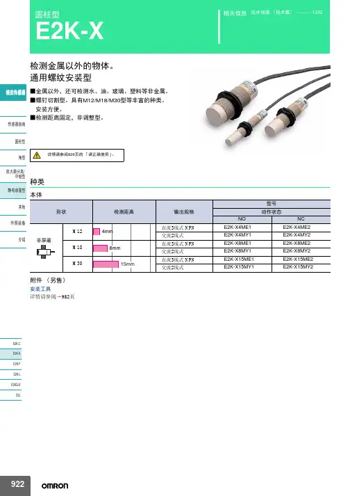
微动开关微动开关概要使用注意事用语说明项微动开关故障解决Q&A■微动开关的定义微动开关具有微小接点间隔和速动机构,用规定的行程和力进行开关动作的接点机构,被外壳覆盖,其外部有传动器,且外形较小。
下图为典型的微动开关构造的一个示例。
微动开关由5个大类的构成要素组成。
微动开关用语说明■一般用语(1)一般用语微动开关:具有微小接点间隔和快动机构,用规定的行程和规定的力进行开关动作的接点结构,用外壳覆盖,其外部有驱动杆的一种开关。
(以下称开关)有接点:在开关类型中,和具有开关特性的半导体开关相比,通过接点的机械开关来实现开关的功能。
接触形式:根据各种用途构成接点的电气输入输出电路[(16)中显示]。
额定值:一般指作为开关特性和性能的保证基准的值,例如额定电流、额定电压等,其前提是特定的条件(负载的种类、电流、电压、频率等)。
树脂固定(塑封端子):在端子部位用导线配线后,通过填充树脂来固定该部分,消除露出的带电部位来提高防滴性的方法。
绝缘电阻:指非连接端子间、各端子和不带电金属部位间、各端子和地间的电阻值。
耐压:在规定的测定部位加1分钟高电压后,不会引起绝缘损坏的临界值。
接触电阻:表示接点的接触部位的电阻,但一般表示包含弹簧和端子部位导体电阻的电阻值。
抗振性:误动作振动微动开关在使用时,由于振动闭合的接点在超过规定的时间内不分离的振动范围。
抗冲击性:耐久冲击指微动开关在运输中或者安装时不会受到由该机械冲击带来的各部位的损伤,并满足动作特性的范围内的冲击。
误动作冲击?指微动开关使用时由于冲击闭合的接点在超过规定的时间内不分离的冲击范围。
(2)关于结构、构造的用语●微动开关的结构、构造(3)有关寿命的用语机械寿命:指接点不通电,以规定的操作频率将过行程(OT)设定为规格值使其运行时的开关寿命。
电气寿命:在接点上连接额定负载,以规定的操作频率将过行程(OT)设定为规格值进行开关时的开关寿命。
(4)标准试验状态开关的试验条件如下。