无线环境监测装置正文(已修改)
- 格式:doc
- 大小:218.50 KB
- 文档页数:14

专利名称:一种用于环境检测用的环境检测装置专利类型:实用新型专利
发明人:赵飞翔
申请号:CN202122320951.5
申请日:20210924
公开号:CN215728108U
公开日:
20220201
专利内容由知识产权出版社提供
摘要:本实用新型公开了一种用于环境检测用的环境检测装置,包括检测装置本体,所述检测装置本体前端中心的顶部安装有操作控制模块,所述检测装置本体一侧中心的顶部转动连接有检修门板,所述检测装置本体内壁的底部中心固定连接有存水箱,所述存水箱顶部中心开设有储水室,所述存水箱顶部两侧的中心均开设有空腔,两个所述空腔的顶部中心均安装有加热组件。
本实用新型通过在检测装置本体内壁固定的第一支架板上安装有检测管、吸水管和微型流量泵,微型流量泵将储水室中加热的水泵吸到检测管中,然后通过定量滴嘴将试剂储存箱中的化学试剂定量滴入检测管中,对水进行酸碱度测定,上述结构代替了人工检测,避免人为操作带来的污染而造成检测结果的偏差。
申请人:赵飞翔
地址:510000 广东省广州市增城区新塘大道西508号康乐东苑7幢105房
国籍:CN
更多信息请下载全文后查看。
《基于无线传感网的环境监测系统的研究与实现》篇一一、引言随着科技的不断进步,环境监测系统已经从传统的有线监测方式转向了无线传感网技术。
无线传感网技术以其灵活性、可扩展性及低成本的特性,在环境监测领域中发挥着越来越重要的作用。
本文旨在探讨基于无线传感网的环境监测系统的研究与实现,分析其关键技术、设计方法及实施效果。
二、无线传感网技术概述无线传感网(Wireless Sensor Network,WSN)是由大量具有感知、计算和通信能力的传感器节点组成的分布式网络系统。
它具有以下特点:低功耗、低成本、灵活的拓扑结构、高容错性以及能够进行大规模的分布式信息采集和处理。
因此,该技术在环境监测、智能家居、军事等多个领域得到了广泛应用。
三、环境监测系统的需求分析环境监测系统主要关注于对环境参数的实时监测和数据分析,包括空气质量、水质、土壤状况等。
因此,系统需要满足以下需求:1. 实时性:能够实时获取环境参数数据,并上传至中心服务器进行分析处理。
2. 准确性:传感器应具有较高的精度和稳定性,以保证数据的准确性。
3. 可靠性:系统应具有较高的可靠性和稳定性,能够适应各种复杂环境。
4. 可扩展性:系统应具有良好的可扩展性,以适应未来可能的扩展需求。
四、系统设计与实现基于上述需求分析,本文设计了一种基于无线传感网的环境监测系统。
该系统主要由传感器节点、网关节点、中心服务器等部分组成。
1. 传感器节点设计传感器节点是整个系统的核心部分,负责采集环境参数数据。
这些节点应具备低功耗、低成本、高精度的特点。
同时,为了实现系统的可扩展性,传感器节点应采用模块化设计,方便后期维护和升级。
2. 网关节点设计网关节点是连接传感器节点和中心服务器的桥梁,负责数据的传输和转发。
这些节点应具备高速的通信能力和良好的数据处理能力,以保证数据的实时性和准确性。
3. 中心服务器设计中心服务器是整个系统的数据中心,负责数据的存储、处理和分析。
应采用高性能的计算机和数据库技术,以支持大量的数据存储和高速的数据处理。
英文Wireless environmental monitoring through wireless mobile munications (GPRS / CDMA) and the Internet (INTERNET) seamless docking with real-time data acquisition, remote transmission, remote storage and web publishing functions, may facilitate the realization of a variety of remote site monitoring and management, through analysis of data mining and the bination of knowledge and experience of experts can provide remote diagnostics of the relevant objects and control management. Wireless remote environmental testing real-time monitoring system integration technology, modern sensor technology, wireless munication, puter network technology as a whole, from the structure and position was divided into three parts: the terminal acquisition transmit modules, the server receives storage module, Web-based data dissemination and analysis modules.Wireless monitoring and control is a remote control unit terminal devices, monitoring and control terminal set A / D functions and I / O functions as one, is responsible for on-site signals, industrial equipment monitoring and control. DTD110 RTU series wireless module is through a long period of Xi'an Datai electronics panies to explore and develop with feedback from users of wireless telemetry remote terminal equipment. The module uses 16-bit low-power16-bit MCU control, and DTD465 series wireless module with wireless telemetry and remote control. Provides 4 analog input and 4 analog outputs; or 4-way switch input, 4-way switch output. Analog can be a 0 ~ 5V voltage signal, it can be 4 ~ 20mA current signal. Industrial field transmitter can capture a variety of analog output, digital signal; to output control signals to control the relay output.There is also a remote wireless environmental monitoring simulation device. For unattended monitoring of remote environmental issues, an experimental simulation system design. Modular design, mainly by the energy harvesting module, the control center module, the sensor monitors the node module, the wireless transmission module and LCD display modules and other ponents. Monitoring center and the monitoring node with AVRAtmega16L microcontroller as the control and monitoring of environmental monitoring nodes encoded by amplitude modulation signal from the wireless transceiver module sent to the monitoring center. Environmental monitoring by the energy harvesting modules supply nodes, without replacing the battery. The system is low power consumption, flexible configuration node, simple structure, can achieve the temperature, humidity and light intensity monitoring, wireless and digital display.Simulator wireless environmental monitoring on the instructions there are so few parts. 1. Monitoring and detection of the terminal nodes with a circular air core coil antenna with a diameter of less than 1mm enameled wire or wire insulation jacket made of a tightly wound 5 turns. Coil diameter (3.4 ± 0.3) cm (One battery can be used for skeleton). Medium between the antenna coil air. Wireless carrier frequencies below 30MHz, modulation custom. Terminal node and detection monitoring shall not be used other than the provisions of the antenna coupling outside. Wireless transceiver circuitry to be made, not by the wireless sending and receiving finished module. Whether the changes in illumination, the method used to achieve occlusion photoelectric sensor. 2. Play some of the basic requirements to be in the detection delay and detection range to meet the requirements under the premise implementation. 3. Testing the detection of the node power consumption of nodes in Figure 2 shows the distribution map, keep a distance D + D1 = 50cm, by measuring the battery supply current detection node A to estimate the power consumption. Current test circuit shown in Figure 3. The figure for the filter capacitor capacitance C, current meter with 3 ½-digit multimeter DC current file and read the normal work of the maximum display value. If the D + D1 reach 50cm, this item is not tested. 4. Body of the report should include the design of the overall system block diagram, the core circuit schematic, the main flow, the main test results. plete circuit diagram, it is important to use accessories given source.Space constraints, you can visit anytime, anywhere Internet, no longer have to network cabling and frustration. However, wireless munication is that people are dream-related technology, with it, we do not have the time during the exchange of data by time and the wireless network technology is too much, after all, good and bad. The current popular technology for a simple introduction.Narrow-band wide area network.1.HSCSDHSCSD (High Speed Circuit Switched Data) for wireless users to provide wireless data transmission rate of 38.3kbps transmission, it is faster than standard GSM munication standard 4 times faster data rate, can be prepared using the fixed telephoneUsers pared to the demodulator. At present, GSM network time slot in each single channel can only support one user, HSCSD by allowing a user at the same time, simultaneous access to multiple channels to dramatically improve data access rate. But the fly in the ointment is that this will lead to user costs. Assuming a standard data transfer rate is 14 400bps, to use with 4 slot HSCSD enable data access rate up to 57.6Kbps. Currently supports HSCSD phone with NOKIA's 6210 and 6250.2.GPRSGPRS (General Packet Radio Service multi-slot) is a very easy interface and IP packet switching business, its rate up to 9.6 ~ 14.4kbps, or even reach 115kbps, and can transmit voice and data. This technology is to improve Internet access speed of the current hot technology, but also may be used in wide area network. GPRS is considered the GSM Phase 2 Enhanced (GSM Phase2 +) access technology. Although GPRS packet data transmission on GSM standard, but can be and IS-136 standard used in bination. With the development of Internet and the popularity of cellular mobile munications, GSM development for all to see, so the prospect of GPRS technology is very broad.GPRS is a new GSM carrier services, improve and simplify the wireless data packet network access method, packet data can be directly in the GSM base stations and other points between the transmission network. It has access to a short time, the rate is high. Because it is a team approach, so you can charge by the number of bytes, the traditional dial-up access to these and a long time, according to the duration of charging circuit was different. At the same time, GPRS GSM network is divided on the network, it actually is the one Internet subnets. In support of GPRS, GSM can provide: E-mail, web browsing, enhanced short message service, instant wireless image transfer, look like a business, text, and shelter sharing, surveillance, Voice over Internet, broadcasting services. Because it uses a group technology with traditional business in the implementation of radio circuits have pletely different characteristics.GPRS network supports both IPv4 and IPv6, is the way to third generation mobile munication network an important step. It is suitable for sudden Internet / Intranet services and can provide point to point carrier services and the pletion of the short message service delivery. Expected in the future, it also provides a single point to multiple points of business. More importantly, GPRS has a limited QoS support, because it can be specified by the relevant parameters inherit the business, reliability, delay, traffic.Currently on the market is still difficult to get support for GPRS mobile phone, and China Mobile currently does not support GPRS. Reported that China Mobile is developing a "Monternet" may apply the technology is GPRS.3.CDPDCDPD (Cellular Digital Packet Data) using packet data mode, is widely recognized as the best wireless public network data munication protocols. It is based on TCP / IP based on an open system architecture, the open interface, high transmission speed, user unit to determine the air link encryption, air data encryption, pression, error correction and retransmission of data and the IP world standards Addressing mode wireless access organically bine to provide seamless connectivity with the network layer, multi-protocol networks.The system consists of wireless sensor multi-point detection coils - Detection of the terminal ponents, to achieve a number of monitoring points (simulation of the actual number of monitoring points with two monitoring points) and the monitoring terminal half-duplex munication, the terminal monitoring points can be monitored real-time acquisition sub- point of the surrounding temperature and light information, and monitoring by the midpoint of the main points - from the data munication between machines, the system uses FSK modulation with a carrier, child monitoring points and monitoring points in the terminal can be battery-powered low power 3V MCU AVR Atmega16L consumption for the control of the core, the pany launched MOTOROLA FM transmitter ICs MC2833 monolithic form FSK modulation circuit, MC3363 monolithic narrowband VHF FM receiver chips FSK demodulation circuit, the photosensitive resistor and the digital temperature sensor posed of sensing DS18B20 system. The design ideas clear, simple and reasonable agency, low cost circuits to achieve most of the features requested topic indicators, monitoring simulation device probe time delay of not more than 5s, munication distance up to 50cm or more.Future wireless munication systems will use a variety of wireless munication technology, users will also be various types of user devices through heterogeneous wireless access networks. For the user, regardless of access technology want to have access to a wealth of wireless munications services. Environment Network's goal is to better plug and play support heterogeneous networks, so a more efficient use of network resources, and from a business point of view to better support the wireless munications market kinds of petition and collaboration modes. This book first describes the overall concept of the network environment and architecture, which focuses on environmental network architecture of the two basic characteristics, namely, environmental control hierarchical model space and the environment; then introduces the overall concept of environmental networks in a number of specific technology, including security, network synthesis, general environmental network signaling, multiple wireless access, mobility management, overlay network, network management context-aware and the environment. This book is the future of the wireless network development and application provides a new perspective. Electronic book available to institutions of higher learning, munication, information processing, puter and other professional or senior undergraduate students with lower grades, but also for engineering and technical personnel in these areas, industry analysts and executives Reference Although the wireless LAN has been gradually accepted by the people in network planning, system configuration, so there are still many users Sidongfeidong. The following describes some of the basics of wireless local area network and application profile.A wireless LAN can be used as an extension to use the wired LAN, wired LAN can also be used as an alternative to independent facilities, the wireless LAN provides a strong networking flexibility. Nevertheless, the formation of the network but there are still many issues to consider, sum up, the following aspects:1. Equipment purchase early preparations.Terms on the purchase of equipment, I always thought that the more important focus on product consistency, that choose the same vendor, the same rate of the product, so you can get the best patibility and stability of the speed. Attention to look at the product packaging, and support for the product only supports the 802.11b 11M wireless speed seems slightly slower but the price is very affordable.The product currently supports most of 54M 802.11g products, is currently the mainstream of speed, its technical support and relevant information is also very plete, is the focus of the optional information; and 802.11g + generally support rate for the 108 108M, this is the future transfer rate within one year of the mainstream, wireless network if you have certain requirements for speed, more appropriate to buy such products, in fact, the price is not quite that expensive, wireless devices Ma, certainly slightly more expensive than the wired devices.2. Topological structure is not chaos.Topology of the network structure has been based on plane, built in the beginning of any network, they should consider the actual network environment.Wired and wireless coexistence environment:If you already have a wired network, to build a wireless network on this basis, it should be considered patible with wired and wireless equipment, in line with the most to do with the least investment in the principles of things; the average family cable network are ADSL Modem + Router structure, the simplest way is to add a wireless AP as a wireless signal relay, and then configure the puter to a wireless network card; the wireless AP does not have a virtual dial-up feature, so it should be connected with the broadband router, near The unified management of a broadband router to wired and wireless networks, and networks to achieve two visits (although such management configuration up more trouble).The configuration is slightly simpler, more convenient way to manage is to replace the wired router with a wireless router, and wireless router can be wired with a LAN port connected to a puter; so that a router can be a good wired and wireless munications. IT168 has the co-existence on the wired and wireless installation and configuration of the article, we refer to can.Separate wireless environment:The establishment of a new wireless network environment, the same remended wireless network card wireless router + structure, because it has maximum flexibility. When you need a wired connection, wireless router's LAN port can provide useful. The specific structures of such environments and configuration of the same articles, please refer to the station, there will not elaborate.3. Signal coverage to be cautious.Although wireless networks out of the shackles of cable, but how to ensure network coverage after the Establishment, it is to pay attention to. This is the main wireless signal transmitter and then place the book side of the issue. General wireless AP or wireless router, the coverage in the open area of about 100m, indoor coverage in the space cut off from the main subject of the situation, usually in the 15m range of the signal can penetrate 20cm of two block partition or wall of brick and concrete structure 20cm cut off and the guarantee of ordinary concrete and stable operation of the network; When the distance is too far away or during the partition is large, the coverage of the wireless network signal does not have enough margin to ensure stable operation of the network.So in order to solve the structure of the building plex of buildings, especially the wireless AP or wireless router within the coverage of small problems, you can increase the wireless AP or wireless router, the layout density, the installation of the antenna gain, and try to ensure that the signal coverage of wireless devices measures used within the solution.After 10 years of development, Wireless LAN technology has matured, applications bee increasingly wide range of applications from small wireless LAN to enter the mainstream. Expects global sales of wireless LAN access point from 50 million units in 2000 increased steadily to 450 million units, the annual increase of 55%. Sales of wireless LAN will be about 3 million in 2000 increased to 34,000,000 in 20XX, the annual increase was 53%. The next few years, wireless LAN technology will be more mature, product performance will be more stable, the market will continuously increase, the price will continue to decrease, large equipment providers will enter the market, most businesses and panies will use wireless LAN internal network building.Faced with such good prospects for development, China should vigorously promote the wireless LAN technology research and practical, to seize the opportunity for the development of wireless local area network. This not only greatly promoted the development process of the State of information, also for China's information industry and telemunications market into the international market with excellent opportunities.中文无线环境监测是通过无线移动通信(GPRS/CDMA)和互联网络(INTERNET)的无缝对接,具有数据的实时采集、远程传输、异地存储和网络发布等功能,可方便实现对各种现场进行远程监控和管理,通过进行数据分析挖掘和专家知识经验的结合,可提供对有关对象的远程诊断与调控管理等功能。
《基于无线传感网的环境监测系统的研究与实现》篇一一、引言随着科技的进步,无线传感网络技术已经在各个领域得到广泛应用。
本文提出的环境监测系统研究与实现正是依托无线传感网络技术,以提高环境监测的实时性、准确性和便捷性。
本文将详细介绍该系统的设计思路、实现过程以及应用效果。
二、系统概述基于无线传感网的环境监测系统主要由传感器节点、网关节点、数据中心等部分组成。
传感器节点负责实时采集环境数据,如温度、湿度、空气质量等;网关节点负责将传感器节点的数据传输至数据中心;数据中心则负责数据的存储、分析和展示。
三、系统设计1. 传感器节点设计传感器节点采用低功耗、小体积的微电子设备,以实现对环境数据的实时采集。
通过选用适当的传感器类型和布置方式,可以确保数据的准确性和实时性。
此外,为提高系统的可靠性和稳定性,我们采用分布式架构设计,将传感器节点分散布置在监测区域内。
2. 无线传感网络设计无线传感网络是系统的重要组成部分,负责实现传感器节点与数据中心之间的数据传输。
我们采用ZigBee等低功耗无线通信技术,以降低系统能耗,提高通信稳定性。
同时,为确保数据传输的实时性,我们设计了多条数据传输路径,以实现数据的快速传输和备份。
3. 数据中心设计数据中心负责数据的存储、分析和展示。
我们采用云计算技术,将数据中心部署在云端,以实现数据的远程访问和共享。
此外,为提高数据的处理能力,我们采用了大数据分析技术,对环境数据进行实时分析和预测。
四、系统实现在系统实现过程中,我们首先对传感器节点进行设计和制作,然后进行无线传感网络的搭建和调试。
在数据中心部分,我们实现了数据的存储、分析和展示功能。
为确保系统的稳定性和可靠性,我们进行了多次实地测试和调试。
五、系统应用基于无线传感网的环境监测系统可以广泛应用于环境保护、农业、林业等领域。
在环境保护方面,该系统可以实时监测空气质量、水质等环境指标,为环境保护提供有力支持。
在农业领域,该系统可以实时监测土壤湿度、温度等数据,为农业生产提供科学依据。
2009年全国大学生电子设计竞赛试题参赛注意事项(1)2009年9月2日8:00竞赛正式开始。
本科组参赛队只能在【本科组】题目中任选一题;高职高专组参赛队在【高职高专组】题目中任选一题,也可以选择【本科组】题目。
(2)参赛队认真填写《登记表》内容,填写好的《登记表》交赛场巡视员暂时保存。
(3)参赛者必须是有正式学籍的全日制在校本、专科学生,应出示能够证明参赛者学生身份的有效证件(如学生证)随时备查。
(4)每队严格限制3人,开赛后不得中途更换队员。
(5)参赛队必须在学校指定的竞赛场地内进行独立设计和制作,不得以任何方式与他人交流,包括教师在内的非参赛队员必须迴避,对违纪参赛队取消评审资格。
【本科组】一、任务设计并制作一个光伏并网发电模拟装置,其结构框图如图1所示。
用直流稳压电源U S 和电阻R S 模拟光伏电池,U S =60V ,R S =30Ω~36Ω;u REF 为模拟电网电压的正弦参考信号,其峰峰值为2V ,频率f REF 为45Hz~55Hz ;T 为工频隔离变压器,变比为n 2:n 1=2:1、n 3:n 1=1:10,将u F 作为输出电流的反馈信号;负载电阻R L =30Ω~36Ω。
RLU S图1 并网发电模拟装置框图二、要求1.基本要求(1)具有最大功率点跟踪(MPPT )功能:R S 和R L 在给定范围内变化时,使d S 12U U ,相对偏差的绝对值不大于1%。
(2)具有频率跟踪功能:当f REF 在给定范围内变化时,使u F 的频率f F =f REF ,相对偏差绝对值不大于1%。
(3)当R S =R L =30Ω时,DC-AC 变换器的效率η≥60%。
(4)当R S =R L =30Ω时,输出电压u o 的失真度THD ≤5%。
(5)具有输入欠压保护功能,动作电压U d (th )=(25±0.5)V 。
(6)具有输出过流保护功能,动作电流I o (th )=(1.5±0.2)A 。
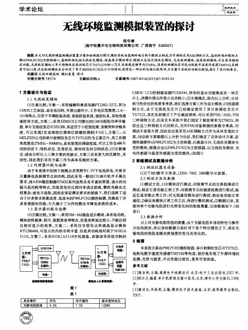
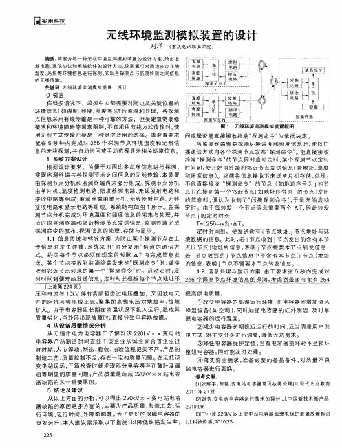
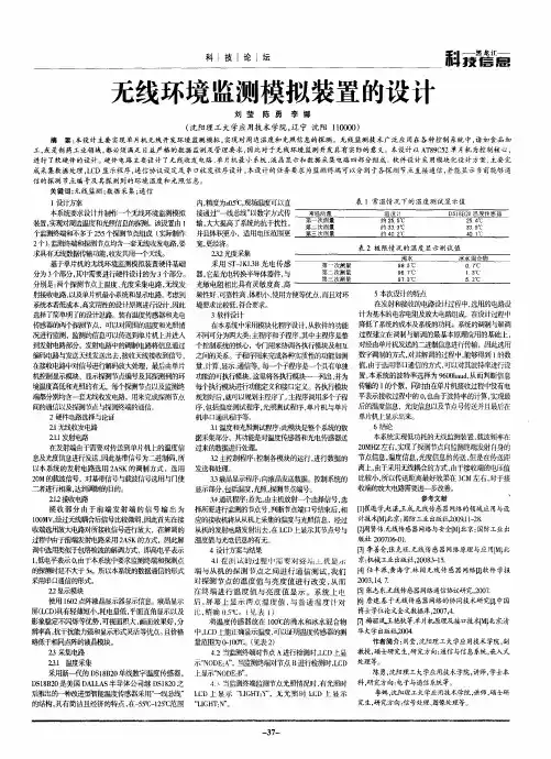
无线环境监测模拟装置的设计摘要:简要介绍一种无线环境监测模拟装置的设计方案,给出收发电路、通信协议和系统软件的设计方法。
该装置可对周边多点环境温度、光照等环境信息进行探测,实现各探测点与监测终端之间信息的无线传输。
关键词:无线环境监测模拟装置设计0 引言在很多情况下,监控中心都需要对周边及关键位置的环境信息(如温度、照度、湿度等)进行监测和处理。
各探测点信息采用有线传输是一种可靠的方法,但受建筑物装修要求和环境障碍等因素限制,不宜采用有线方式传输时,使用无线方式传输无疑是一种经济适用的选择。
本装置要求能在5秒钟内完成对255个探测节点环境温度和光照信息的无线探测,并自动巡回或手动选择显示相关环境信息。
1 系统方案设计根据设计要求,为便于对周边多点环信息进行探测,实现监测终端与各探测节点之间信息的无线传输,本装置由探测节点分机和监测终端两大部分组成。
探测节点分机由单片机、温度检测电路、照度检测电路、无线发射电路和接收电路等组成;监测终端由单片机、无线发射电路、无线接收电路和显示电路等组成。
系统结构如图1所示。
各探测节点分机完成对环境温度和照度信息的采集与处理,并适时向监测终端和邻近检测节点发送信息;监测终端完成探测命令的发布、探测信息的处理、存储与显示。
1.1 信息传送与转发方案为防止某个探测节点在上传信息时发生碰撞,系统采用“时分复用”信道的通信方式。
约定每个节点必须在规定的时隙δt内完成信息发送。
某个节点接收到监测终端发来的“探测命令”时,或接收到邻近节点转来的第一个“探测命令”时。
启动定时,定时时间到便开始发送信息。
定时时长根据每个节点地址不同或是否能直接接收终端“探测命令”为依据决定。
当监测终端需要探测环境温度和照度信息时,便以广播通信方式向各个探测节点发布“探测命令”。
能直接接收终端“探测命令”的节点同时启动定时,某个探测节点定时时间到,便开始向终端和邻近节点发送信息(含地址、温度和照度信息)。
无线环境监测装置摘要摘要:本无线环境检测装置采用单片机为主控制器。
设计的主要思路是通过传感器监测环境温度的变化和光照的有无,并将采集的数据传输给单片机(MCU)进行初步处理,再通过带有自定义无线传输协议的电路传送给控制终端,并在控制终端上显示采集到的环境信息。
关键字:无线传输;传输协议;传感器;目录1 引言 (1)2方案设计 (1)2.1 各模块电路的方案选择与论证 (1)2.1.1 主机控制模块 (1)2.1.2 显示模块 (1)2.1.3 温度光照检测模块 (1)2.1.4 无线收发模块 (2)2.2 模块的最终选择 (2)3系统电路分析 (2)3.1 发射电路分析 (2)3.2其他电路请见附表 ............................ 错误!未定义书签。
4硬件的设计与实现.. (3)4.1 无线收发模块 (3)3.2 温度与光照的检测部分 (3)3.3 显示模块 (3)4 软件设计 (3)4.1子程序流程图 (3)4.2主程序流程图 (4)5 系统测试 (4)5.1测试方法与仪器 (4)5.1.1 测量方法 (4)5.1.2 测量用到的仪器 (4)5.2测试的结果 (4)5.3结果分析 (5)6 结论 (5)参考文献 (6)附录1:电路图图纸 (7)附录2:程序清单 (9)1 引言现代工业对环境温度、光照的控制要求越来越高,许多车间在生产特定产品时都需要对车间温度、光照进行监控,本作品能满足市场对这类产品的需求。
本作品用光电三极管、温度传感器收集环境数据,用单片机控制无线发射模块发射数据,无线接收模块接收,同时用单片机将传送的数据显示在液晶显示屏上。
软件采用C语言编程。
本作品具有能耗低、传播距离远、探测灵敏度高等优点。
2方案设计根据题目要求本作品可以分为以下几部分:显示模块、主机控制模块、无线收发模块和环境温度光照检测模块,如图2.1所示。
图2.1 系统方案设计模块图2.1各模块电路的方案选择与论证2.1.1主机控制模块方案一:采用51单片机控制系统。
单片机算术运算功能强,软件编程灵活、自由度大,可用软件编程实现各种算法和逻辑控制,并且有功耗低、体积小、技术成熟和成本低等优点,能满足题目要求。
方案二:采用FPGA(现场可编程逻辑门阵列)作为系统的控制核心。
由于FPGA具有强大的资源,使用方便灵活,易于进行功能扩展,并且可应用EDA软件仿真、调试,易于进行功能扩展。
但其成本偏高,引脚较多,硬件电路布线复杂。
根据以上具体分析选择方案一。
2.1.2显示模块方案一:采用液晶显示屏。
液晶显示屏(LCD)具有功耗小、轻薄短小无辐射危险,平面直角显示以及影象稳定不闪烁,可视面积大,画面效果好,抗干扰能力强等特点。
方案二:采用四位七段数码显示管分别显示光照的有无、温度的百、十、个位。
数码管具有:低能耗、低损耗、低压、寿命长、耐老化,对外界环境要求较低。
同时数码管采用BCD编码显示数字,程序编译容易,资源占用较少。
根据题目要求选择方案一。
2.1.3温度光照检测模块温度传感器的选择方案:方案一:采用热敏电阻,此元件虽然价格便宜,但是其非线性特性会影响系统精度。
方案二:选用美国Dallas 半导体公司的数字化温度传感器DS18B20。
DS18B20为数字式温度传感器,无需其他外加电路,直接输出数字量。
可直接与单片机通信,读取测温数据,电路简单。
此器件具有体积小、抗干扰强、价格便宜、性能稳定等优点其各方面特性都满足此系统的设计要求根据以上分析选择方案二。
因为只需检测光的有无,所以可以选择灵敏度较好的光敏三级管。
2.1.4 无线收发模块方案一:非编码方案采用模拟信号发送,模拟信号传输,模拟信号接收。
此方案的特点是使用元件简单,价格便宜,但是与数字电路的融合性差,对数据处理带来很多不变。
方案二:编码方案采用专业的无线信号编解码芯片,从而实现数字信号的输入,模拟信号的传输,数字信号的输出。
因本设计采用MCU 做主控芯片,为了便于信息的处理,故选择方案二。
2.2 模块的最终选择根据以上分析并结合具体的条件,最终选择如下模块:1. 主机控制模块采用51单片机用以实现对LCD 显示、信息的传送、温度的采集、光照的探测。
2. 显示模块用液晶显示器用来显示实时温度及光照的有无。
3. 光照检测模块采用光敏三极管,温度探测模块采用采用数字温度传感器DS18B20。
4. 无线收发模块采用TX-2B/RX-2B 芯片作为编解码芯片。
3 系统电路分析 3.1 发射电路分析根据题目要求,本系统的载波频率低于30MHz ,考虑到电路设计和调试的方 便,采用石英晶体作为振荡器。
石英晶体的等效为静态电容和电感、电阻、电容并联起来的电路。
忽略电阻的影响,可以看出石英晶体具有俩个谐振频率:一个是由电感、电阻、电容串联谐振频率:f =(3.1.1)另一个是由电感、电阻、电容并联谐振频率:f f==(3.1.2)这样使得等效电感的电抗曲线非常陡峭,故采用此电路。
3.2其他电路请见附表4硬件的设计与实现4.1无线收发模块该模块是系统中除单片机外的核心模块, TX-2B/RX-2B内部已含有编码和解码电路,无需在后续的电路中对接收到的信号进行软件编程解码,因此硬件电路简单。
RX-2B包括内置放大器、运算器及锁存器等。
振荡输入输出端外接100欧电阻形成RC振荡器,与发射电路的频率匹配。
RX-2B接收信号后,经解码后将温度和光照信息由和TX-2B相对应的引脚输出,传给单片机。
具体电路请参考附录。
3.2温度与光照的检测部分本系统光照检测采用光敏三级管,当具有光敏特性的PN节受光照射时,形成光电流,由此产生的光电流由基极进入发射极,从而在集电极得到一较大电流。
由于题目只要求检测光的有无,因此要求电路比较灵敏,能检测到光照强度较小的光。
在制作这部分电路时,改变电路中的电阻,比较各电阻所得的结果,从中选出能较好满足题目要求的电阻。
温度传感器采用DS18B20数字温度传感器,DS18B20体积小,适用电压宽,测量温度范围及测量精度都能满足题目要求,直接输出数字量,并且可以直接与单片机通信,简化了电路的设计。
从站同时安装34063升压芯片,此芯片将3V电压升到5V,同时为无线收发模块及温度与光检测模块供电,简化了电路设计。
测温、光检及升压电路如附录1图3.2所示。
3.3显示模块本系统显示电路,我们采用单片机STC89C58 作为电路的控制核心,用12864液晶显示屏显示从站的编号、环境的温度、光的强度。
为了实现题中提出能扩展到256个从站的能力。
显示时:按键S1控制复位电路,按键S2用来翻屏,按键S3、S4分别用来翻页。
单片机XTAL1、XTAL2接十二MHZJ晶振,提供时钟基值。
具体电路图见附录1图3.3。
4 软件设计4.1 子程序流程图图4.1 子程序流程图4.2 主程序流程图5 系统测试5.1 测试方法与仪器5.1.1 测量方法根据题中要求及本作品具体特点可以分别测量发射的距离、系统误差、响应时间四项。
一、发射距离的测量:根据本作品具体的特点,先将发射模块与接收模块分开8cm,打开电源,使发射模块发射信息,看接收模块是否能接收到信息。
以2cm 的间隙增大发射距离,直至接收模块不能接收信息为此,记录测量的数据。
二、系统误差的测量:本系统要求温度测量绝对误差小于2℃。
将系统放在一空调房中,将空调通电,改变室内温度,用温度计测量室内温度作实际温度,同时将系统通电将液晶显示器显示温度作测量温度,记录测量的数据。
三、响应时间的测量:按下电源按钮,用秒表记录按下电源按钮的时刻,眼睛观测液晶显示器直至其上显示的数据稳定,用秒表记下数据稳定时的时刻,采用多次测量取平均值的方法,并分别记录这两个时刻。
5.1.2测量用到的仪器根据测量方法,所用到的仪器有:电压表、电流表、直尺、温度计、秒表、空调。
5.2 测试的结果表 5.2.3响应时间的测量结果5.3 结果分析从以上测试结果可以看出本作品基本上能满足题目要求的基本部分,及部分发挥部分。
从上表中可以看出,无线通信距离远远于题中要求;由于DS18B20测温灵敏度高、稳定,随意系统误差也较小;响应时间虽有人为误差但也能满足题中要求的5秒以内。
6 结论通过设计本产品,我们加深了对DS18B20数字温度传感器、光敏三极管、TX-2B/RX-2B芯片的认识,熟练了单片机的编程及无线通信的相关知识。
本作品基本上完成了题中要求的基本部分,对发挥部分的第一点及第三点要求也完成的很好。
本作品能很好的监控环境温度的变化及光照的有无,但还有许多值得改进的地方如无线通信模块较复杂,通信距离随能满足体重要求还是相对较短。
综上所述本作品还是能很好的完成题中要求,且具有电源能耗低、发射距离较远、系统误差小等优点。
参考文献《单片机原理及应用》,李建忠著,西安:西安电子科技大学,2002年;《高频电子线路》,胡宴如、耿苏燕著,北京:高等教育出版社,2004年;《模拟电子技术基础简明教程》,清华大学电子学教研组,杨素行著,北京:高等教育出版社,2005年;《数字电子技术基础》,阎石著,北京:高等教育出版社,1997年;《无线发射与接收电路设计》,黄智伟著,北京:北京航空航天大学出版社,2004年;附录1:电路图图纸图3.1.1 发射部分电路图图3.1.2 接收部分电路图图3.2光照温度检测模块电路图图3.3显示模块电路图附录2:部分程序清单主机程序:include<reg52.h>#define uchar unsigned char#define uint unsigned intsbit Lcd_rs=P1^1;sbit Lcd_en=P1^0;sbit Down=P1^2;sbit Up=P1^3;sbit Function=P1^4;uchar Num=1;uchar Table[8] ={0x00,0x00,0x00,0x00,0x00,0x00,0x00,0x00} ; uchar code Table1[]="编号: ";uchar code Table2[]="温度: ";uchar code Table3[]="光照信息: ";uchar code Table4[]="联机状态: ";sbit Clk=P3^2;sbit Data=P3^6;/************************* 函数名称: Delayms** 功能描述: 延时,单位毫秒** 输入: 延时毫秒数** 输出 : 无** 全局变量: 无** 调用模块: 无************************/void Delayms(uint k){uchar j;for(;k>0;k--)for(j=125;j>0;j--);}void Delayus (uint us){while(us--);}/******************************* 函数名称: Lcd_WCom** 功能描述: 液晶写指令函数** 输入: 指令** 输出 : 无** 全局变量: 无** 调用模块: 延时函数Delayms() ******************************/ void Lcd_WCom(uchar com){P0=com;Lcd_rs=0;Lcd_en=0;Delayus(5);Lcd_en=1;Delayus(5);Lcd_en=0;}/***************************** ** 函数名称: Lcd_WDate** 功能描述: 液晶写字符函数** 输入: 输入一个要显示字符,** 输出 : 无** 全局变量: 无** 调用模块: 延时函数Delayms() ******************************/ void Lcd_WDate(uchar date){P0=date;Lcd_rs=1;Lcd_en=0;Delayus(5);Lcd_en=1;Delayus(5);Lcd_en=0;}/***************************** ** 函数名称: Disp_string** 功能描述: 在液晶上显示字符。