Varlogic+NR6、(NR12)功率因数控制器++用户手册(2010)
- 格式:pdf
- 大小:10.46 MB
- 文档页数:33

USER MANUALIMPORT ANT SAFETY INSTRUCTIONSWARNING: When using electric products, basic cautions should always be followed, including the following.1. Read all safety and operating instructions before using this product2. The product should be powered by a three pin `grounded (or earthed) plug connected to a power socket with a grounded earth outlet.3. All safety and operating instructions should be retained for future reference4. Obey all cautions in the Operating instructions and on the back of the unit5. All operating instructions should be followed6. This product should not be used near water, i.e. a bathtub, sink, swimming pool, wet basement, etc.7. This product should be located so that its position does not interfere with its proper ventilation. It should not be placed flat against a wall or placed in a built up enclosure that will impede the flow of cooling air.8. This product should not be placed near a source of heat such as stove, radiator, or another heat producing amplifier.9. Connect only to a power supply of the type marker on the unit adjacent to the power supply cord.10.Never break off the ground pin on a power supply cord.11.Power supply cords should always be handled carefully. Never walk or place equipment on power supply cords. Periodically check cords for cuts or signs of stress, especially at the plug and the point where the chord exits the unit.12.The power supply cord should be unplugged when the unit is to be unused for long periods of time.13.If this product is to be mounted in an equipment rack, rear support should be provided.14.The user should allow easy access to any mains plug, mains coupler and mains switch used in conjunction with this unit thus making it readily operable.15.Metal parts can be cleaned with a damp cloth. The vinyl covering used on some units can be cleaned with a damp cloth or ammonia based household cleaner if necessary. Disconnect the unit from the power supply before cleaning.16.Care should be taken so that objects do not fall and liquids are not spilled into the unit through any ventilation holes or openings. On no account place drinks on the unit.17. A qualified service technician should check the unit if:18.The user should not attempt to service the equipment. All service work is done by a qualified service technician.19. Exposure to extremely high noise levels may cause a permanent hearing gloss. Individuals vary considerably in susceptibility to noise induced hearing loss, but nearly everyone will lose some hearing if exposed to sufficiently intense noise for a sufficient time. The U.S. Government's Occupational Safety and Health Administration (OSHA) has specified the following permissible noise level exposure. Duration Per Day In Hours Sound Level dBA, slow response8 9069249539721001 ½1021105½110¼ or less 115According to OSHA, any exposure in excess of the above permissible limits could result in some hearing loss. Ear plugs or protectors in the ear canals or over the ears must beworn when operating this amplification system in order to prevent a permanent hearing loss if exposure exceeds the limits set forth above. T o ensure against potentially dangerous exposure to high sound pressure levels it is recommended that all persons exposed to equipment capable of producing high sound pressure levels such as this amplification system be protected by hearing protectors while this unit is in operation.!The power cord has been damaged!Anything has fallen or spilled into the unit !The unit does not appear to operate correctly!The unit has been dropped or the enclosure damaged.BEFORE SWITCHING ONAfter unpacking your amplifier check that it is factory fitted with a three pin 'grounded' (or earthed) plug. Before plugging into the power supply ensure you are connecting to a grounded earth outlet.If you should wish to change the factory fitted plug yourself, ensure that the wiring convention applicable to the country where the amplifier is to be used is strictly conformed to. A s an example in the United Kingdom the cable colour code for connections are as follows.NOTEThis manual has been written for easy access of information. The front and rear panels are graphically illustrated, with each control and feature numbered. For a description of the function of each control feature, simply check the number with the explanations adjacent to each panel.Y our Laney amplifier has undergone a thorough two stage, pre-delivery inspection, involving actual play testing.When you first receive your Laney Bass amp, follow these simple procedures:(i) Ensure that the amplifier is the correct voltage for the country it is to be used in.ii) Connect your instrument with a high quality shielded instrument cable. Y ou have probably spent con siderable money on your amplifier and guitar - don’t use poor quality cable it won’t do your gear justice.Please retain your original carton and packaging so in the unlikely event that some time in the future your amplifier should require servicing you will be able to return it to your dealer securely packed.Care of your Laney amplifier will prolong it's life.....and yours!EARTH OR GROUND - GREEN/YELLOW NEUTRAL - BLUELIVE - BROWNINTRODUCTIONThe RB6 is a 165W kickback style bass combo with a 15 inch loudspeaker and a high frequency horn in a sturdy wooden cabinet. Its features include; two ¼” jack inputs for Normal / Hi level signals, a gain control and a switchable compressor, a flexible EQ system with Bass, two swept Mids, T reble, and a rotary Enhance control, a power amplifier limiter which can be switched in/out as needed, and a balanced XLR Direct out is present should you need to connect to a PA or recording device. The built in horn may be switched on/off as required. On the rear is an FX loop for connection of external FX, a dedicated output for a tuner and an external speaker socket for connecting additional cabinets. An explanation of these features follows on pages 6-8.Dear Player,Thank you very much for purchasing your new Laney product and becoming part of the worldwide Laney family. Each and every Laney unit is designed and built with the utmost attention to care and detail, so I trust yours will give you many years of ney products have a heritage which stretches back to 1967 when I first began building valve amplifiers in my parent’s garage. Since then we have moved on from strength to strength developing an extensive range of guitar, bass, public address and keyboard amplification products along with a list of Laney endorsees that includes some of the world’s most famous and respected musicians. At the same time we believe we have not lost sight of the reason Laney was founded in the first place - a dedication to building great sounding amplification for working musicians. Warm Regards,Lyndon Laney CEONormal and High inputs are provided for connection of bass guitars. High output basses, either Active or Passive should beconnected via the High socket. Low output basses should be connected using the normal input. High output basses may also be placed in the Normal input if pre-amp overloading is desired.This control is used to set the level of gain present in the pre-amp. producing distortion. The Gain control should be used in conjunction with the signal characteristics.Engages and disengages the on-board compressor, this compresses the input-signal giving a punchier sound. In association with the compressor are two LEDs, one indicating that the compressor is engaged and one indicating the compressor is active. The amount of compression is controlled by the Gain control. The higher the setting the more compression. With most guitars compression will begin at about 5-6 on the control. It is possible to have the compressor engaged but it only be active during certain periods of playing - typically the most dynamic sections.The Enhance control provides an increased definition at the low-end of the frequency spectrum giving you a tighter, punchier sound. The Enhance control does this by providing a dip in the frequency-response of the amplifier at approximately 150Hz. This dip reduces some of the harmonics of the important low-frequencies around 40-80 Hz producing better definition to your sound. T urning the control through to its maximum has the effect of boosting both the low and high-frequency content.FRONT P ANEL CONTROLSControls the boost and cut of the low-frequency response of the pre-amplifier.To access low Lo mid-frequencies turn the frequency control anticlockwise, to access higher Lo mid frequencies turn the frequency control clockwise.frequency-cut, turn the control anti-clockwise.T oaccess low Hi mid-frequencies turn the frequency control anticlockwise, to access higher Hi mid-frequencies turn the frequency control clockwise.frequency-cut, turn the control anti-clockwise.Controls the boost and cut of the high-frequency response of the pre-amplifier.Allows the on-board limiter to be defeated if desired. With the switch in the out position the limiter is engaged.The limiteris automatically triggered at high-output levels and is designed to prevent power-amp distortion at high-output levels.When the limiter is automatically triggered the LED lights up to indicate the limiter is active. It is possible to have the limiterengaged but not have the LED active. The limiter monitors both power-amp clipping and speaker load so it automaticallyregisters the cabinet-impedance and sets itself accordingly.Sets the overall listening level of the amplifier.Activates the on-board high frequency horn.XLR socket for direct-injection of the amplifier signal to a mixing-desk or additional power-amplifier. The XLR socketprovides a balanced low-impedance output-signal from the pre-amplifier taken before any tone correction.Indicates power is connected and the amplifier is switched on.(Always switch off and disconnect power cord when not in use)Main power on/off switchPower inlet socket. Connect to your power source. Make sure the specified voltage is correct for your country! This drawer contains the main safety fuse for the unit.USE ONLY THE CORRECT SIZE AND RATING OF FUSE AS SPECIFIED ON THE PANEL. The mains fuse ratings are detailed in the specs section at the rear of this manual.Serial Number and model of your unit.This socket(s) should be used to connect an extension-cabinet. The impedance of the extension-cabinet must not be less than 8 Ohms. Connecting cabinets that have a lower impedance than 8 Ohms will result in the amplifier overheating. Continual use in this manner may cause permanent damage. Connecting a cabinet with an impedance of greater than 8 Ohms will cause no damage to the amplifier but will result in a reduced output level. (When using an extension cabinet the internal speaker remains connected)Socket for connecting external tuner. This output taken before any EQ so the Volume control may be turned down for silent tuning.Send and return sockets are provided for connecting external effects-units. Y ou can also use the Send socket as a line out if youREAR P ANEL CONTROLSo u d s p e a k e r C a b l eTuner InputThis loop is a series type so allSPECIFICA TIONSSupply Voltage ~100V , ~120V , ~220V , ~230V , ~240V 50/60Hz Factory Option Mains Fuse ~220V>~240V = T2A L. ~100>@120V = T5A L (Time delay)Power Consumption 300WOutput Power Rating 165WLoudspeaker 15” Custom Designed Driver + high frequency horn Features Normal + Hi InputsSwitchable Compressor with status lightsSwitchable Limiter with status lightSwitchable high frequency HornKickback style cabinetEnhanceEQ Bass (Shelving)T reble (Shelving)Lo Paramid (1KHz Peaking)Hi Paramid D.I.Y es, Balanced XLRT uner Out Y esExtension Loudspeaker Socket Y es (8 Ohms minimum)FX Loop Y es (0dBu Nominal) (Series-Insert)Input Impedance 1M Ohm/100pFFX Loop Level (Nominal)700mV/0dBuRecommended Min Extension Speaker Power 150WRecommended Richter Extension Cab RB410 / RB115Size 565*502*490(H*W*D)Unit Weight 26.5Kg (Kg)Packing Weight 29Kg (Kg)±12dB at 40Hz,±15dB at 3.5KHz, ±12dB at 100Hz > (±12dB at 400Hz >4KHz Peaking)This product conforms to: European EMC directive(2004/108/EC), Low Voltage Directive (72/23/EEC) and CE mark Directive (93/68/EEC)Page 11 /12Laney OPERATING INSTRUCTIONSIn the interest of continued product development, Laney reserves the right to amend product specification without prior notification.POWER TO THE MUSIC Laney@。
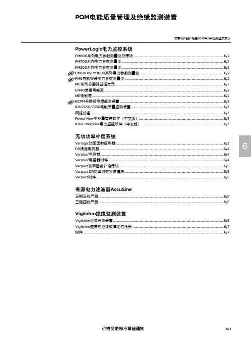
6/ 16PowerLogic 电力监控系统PM800系列电力参数测量仪及模块 ...........................................................................................................6/2PM700系列电力参数测量仪 .........................................................................................................................6/2PM200系列电力参数测量仪 .........................................................................................................................6/2DM6000/PM1000系列电力参数测量仪....................................................................................................6/2PM9导轨安装电力参数测量仪 .....................................................................................................................6/2MC 系列多回路监控单元 .................................................................................................................................6/2EN40单相电能表 ..............................................................................................................................................6/2ME 电能表 ............................................................................................................................................................6/2BCPM 多回路电源监测装置 ...........................................................................................................................6/3ION7650/7550电能质量监测装置 ..............................................................................................................6/3网络设备..............................................................................................................................................................6/3PowerView 电能量管理软件(中文版) ....................................................................................................6/3ION Enterprise 电力监控软件(中文版) .................................................................................................6/3无功功率补偿系统Varlogic 功率因数控制器 ................................................................................................................................6/3DR 调谐电抗器 ...................................................................................................................................................6/4Varplus 2电容器 ..................................................................................................................................................6/4Varplus 2电容器附件 .........................................................................................................................................6/4Varpact 功率因数补偿模块 ............................................................................................................................6/5Varpact DR 功率因数补偿模块 ......................................................................................................................6/5Varpact 附件 .......................................................................................................................................................6/5有源电力滤波器AccuSine三相三线产品.....................................................................................................................................................6/5三相四线产品.....................................................................................................................................................6/5Vigilohm 绝缘监测装置Vigilohm 绝缘监测装置 ...................................................................................................................................6/6Vigilohm 便携式绝缘故障定位设备 ............................................................................................................6/7附件 ......................................................................................................................................................................6/7PQM 电能质量管理及绝缘监测装置本章节产品价格自2010年2月1日起正式执行本章节产品价格自2010年2月1日起正式执行PQM电能质量管理及绝缘监测装置PM800PM7006PM200DM6000/PM1000PM9MC18EN40P(1) DM6000/PM1000系列电力参数测量仪预期将于2010年3月1日开始销售6/ 2PQM 电能质量管理及绝缘监测装置本章节产品价格自2010年2月1日起正式执行6/ 36Varlogic 控制器EGX100ION Enterprise 电力PowerView 电能ION7650/7550ME4zrtBCPMPQM 电能质量管理及绝缘监测装置本章节产品价格自2010年2月1日起正式执行6/ 46三台Varplus 2组合单台Varplus 2电容器PQM 电能质量管理及绝缘监测装置本章节产品价格自2010年2月1日起正式执行6/ 56Varpact 功率因数补偿模块Varpact DR 功率因数补偿模块PQM 电能质量管理及绝缘监测装置本章节产品价格自2010年2月1日起正式执行6/ 66XML316/308XM300C TR22A/TR22AH EM9BVXD312PQM 电能质量管理及绝缘监测装置本章节产品价格自2010年2月1日起正式执行6/ 76Cardew C 浪涌抑制器便携式绝缘故障定位设备套装。
前言现如今,电能是现代生产生活的主要能源和动力。
电能即易于由其他形式的能量转换而来,也易于转换为其他相识的能量以供应用。
我国的电力工业已居世界前列,但与发达国家相比还是有一定的差距,我们人均电量水平还很低,电力工业分布也不均匀,还不能满足国民经济发展的需要。
电力市场还未完善,管理水平、技术水平都有待提高。
随着我国经济的快速发展,电力用户的配电装置和用电设备的容量不断增加,对建筑配电和用电设备的安装提出了更高的要求。
我国的改革开放,为建筑电器领域大量采用新设备新工艺创造了条件。
为了配合实现建筑电器现代化,适应内线安装技术迅速发展的需要,提高建筑安装电工的业务技术水平,确保电气安装、施工质量安全可靠,保证低压电网的安全、经济运行,对建筑的供配电进行合理的负荷计算以及对相应的变电所进行继电保护和瓦斯保护是有必要的。
第一章负荷计算及无功补偿1.1负荷的分级1.1.1电力负荷的概念电力负荷又称电力负载。
它有两种含义:一是指耗用电能的用电设备或用电单位,如说重要负荷、不重要负荷、动力负荷、照明负荷等。
另一种是指用电设备或用电单位所耗用的电功率或电流大小,如说轻负荷(轻载)、重负荷(重载)、空负荷(空载)、满负荷(满载)等。
电力负荷的具体含义视具体情况而定。
1.1.2 电力负荷的分级电力负荷分级的意义,在于正确地反映电力负荷对供电可靠性要求的界限,以便恰当地选择适合我国实际水平的供电方式,满足我国四个现代化建设的需要,提高投资的效益。
根据对供电可靠性的要求及中断供电造成的损失或影响的程度分为三级:(1)一级负荷①中断供电将造成人身伤亡者。
②中断供电将在政治、经济上造成重大损失者,例如重大设备损坏、重大产品报废、重要原料生产的大量报废、国民经济中重点企业的连续生产过程被打乱需要长时间才能恢复等。
③中断供电将影响有重大政治、经济意义的用电单位的正常工作者,例如重要交通纽约、重要通信纽约、重要宾馆、大型体育场、经常用于国际活动的大量人员集中的公共场所等用电单位中的重要电力负荷。
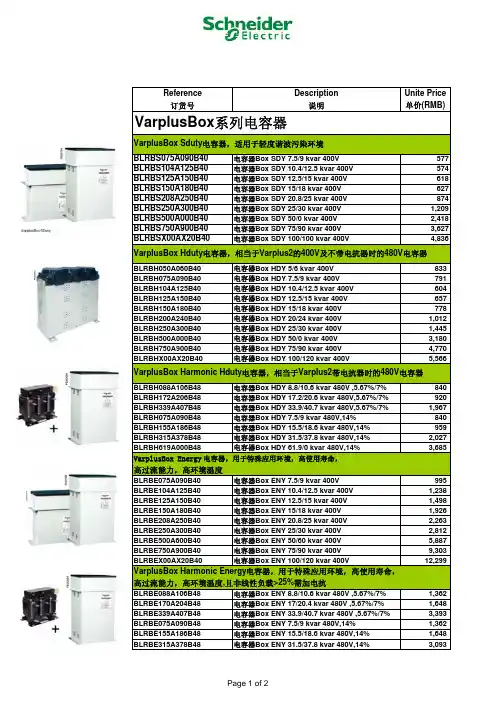
ReferenceDescription Unite Price订货号说明单价(RMB)BLRBS075A090B40电容器Box SDY 7.5/9 kvar 400V 577BLRBS104A125B40电容器Box SDY 10.4/12.5 kvar 400V 574BLRBS125A150B40电容器Box SDY 12.5/15 kvar 400V 618BLRBS150A180B40电容器Box SDY 15/18 kvar 400V 627BLRBS208A250B40电容器Box SDY 20.8/25 kvar 400V 874BLRBS250A300B40电容器Box SDY 25/30 kvar 400V 1,209BLRBS500A000B40电容器Box SDY 50/0 kvar 400V 2,418BLRBS750A900B40电容器Box SDY 75/90 kvar 400V 3,627BLRBSX00AX20B40电容器Box SDY 100/100 kvar 400V 4,836BLRBH050A060B40电容器Box HDY 5/6 kvar 400V 833 BLRBH075A090B40电容器Box HDY 7.5/9 kvar 400V 791 BLRBH104A125B40电容器Box HDY 10.4/12.5 kvar 400V 604 BLRBH125A150B40电容器Box HDY 12.5/15 kvar 400V 657 BLRBH150A180B40电容器Box HDY 15/18 kvar 400V 778 BLRBH200A240B40电容器Box HDY 20/24 kvar 400V 1,012 BLRBH250A300B40电容器Box HDY 25/30 kvar 400V 1,445 BLRBH500A000B40电容器Box HDY 50/0 kvar 400V 3,180 BLRBH750A900B40电容器Box HDY 75/90 kvar 400V 4,770 BLRBHX00AX20B40电容器Box HDY 100/120 kvar 400V 5,566 BLRBH088A106B48电容器Box HDY 8.8/10.6 kvar 480V ,5.67%/7%840 BLRBH172A206B48电容器Box HDY 17.2/20.6 kvar 480V,5.67%/7%920 BLRBH339A407B48电容器Box HDY 33.9/40.7 kvar 480V,5.67%/7%1,967 BLRBH075A090B48电容器Box HDY 7.5/9 kvar 480V,14%840 BLRBH155A186B48电容器Box HDY 15.5/18.6 kvar 480V,14%959 BLRBH315A378B48电容器Box HDY 31.5/37.8 kvar 480V,14%2,027 BLRBH619A000B48电容器Box HDY 61.9/0 kvar 480V,14%3,685 BLRBE075A090B40电容器Box ENY 7.5/9 kvar 400V 995 BLRBE104A125B40电容器Box ENY 10.4/12.5 kvar 400V 1,238 BLRBE125A150B40电容器Box ENY 12.5/15 kvar 400V 1,498 BLRBE150A180B40电容器Box ENY 15/18 kvar 400V 1,926 BLRBE208A250B40电容器Box ENY 20.8/25 kvar 400V 2,263 BLRBE250A300B40电容器Box ENY 25/30 kvar 400V 2,812 BLRBE500A600B40电容器Box ENY 50/60 kvar 400V 5,887 BLRBE750A900B40电容器Box ENY 75/90 kvar 400V 9,303 BLRBEX00AX20B40电容器Box ENY 100/120 kvar 400V 12,299 BLRBE088A106B48电容器Box ENY 8.8/10.6 kvar 480V ,5.67%/7%1,362 BLRBE170A204B48电容器Box ENY 17/20.4 kvar 480V ,5.67%/7%1,648 BLRBE339A407B48电容器Box ENY 33.9/40.7 kvar 480V ,5.67%/7%3,393 BLRBE075A090B48电容器Box ENY 7.5/9 kvar 480V,14%1,362 BLRBE155A186B48电容器Box ENY 15.5/18.6 kvar 480V,14%1,648 BLRBE315A378B48电容器Box ENY 31.5/37.8 kvar 480V,14%3,093VarplusBox Energy 电容器,用于特殊应用环境,高使用寿命,高过流能力,高环境温度VarplusBox Harmonic Energy 电容器,用于特殊应用环境,高使用寿命,高过流能力,高环境温度,且非线性负载>25%需加电抗VarplusBox 系列电容器VarplusBox Sduty 电容器,适用于轻度谐波污染环境VarplusBox Hduty 电容器,相当于Varplus2的400V 及不带电抗器时的480V 电容器VarplusBox Harmonic Hduty 电容器,相当于Varplus2带电抗器时的480V 电容器ReferenceDescription Unite Price 订货号说明单价(RMB)51563调谐电抗器 6.25Kvar/134Hz3,500 51564调谐电抗器 12.5Kvar/134Hz4,000 51565调谐电抗器25Kvar/134Hz7,200 51566调谐电抗器 50Kvar/134Hz9,000 51567调谐电抗器 100Kvar/134Hz14,000 51568调谐电抗器 6.25Kvar/189Hz2,650 52352调谐电抗器 12.5Kvar/189Hz3,100 52353调谐电抗器 25Kvar/189Hz5,900 52354调谐电抗器 50Kvar/189Hz7,500 51573调谐电抗器 6.25Kvar/210Hz2,800 52404调谐电抗器 210Hz 12.5 kvar3,100 52405调谐电抗器 210Hz 25 kvar5,900 52406调谐电抗器 210Hz 50 kvar7,500 52407调谐电抗器 210Hz 100 kvar9,209524486步无功自动补偿控制器 Varlogic NR64,217 5244912步无功自动补偿控制器 Varlogic NR125,481 52450APFR 12 step with Har. NRC127,500 52451Commun RS485 Modbus for NRC125,532 51459copper bar for connection161 51461protective cover IP20/IP42188 Varlogic功率因数控制器DR调谐电抗器。

电气知识培训主要培训内容:一.无功功率补偿柜.二.施耐德常用产品选型说明(Masterpact MT/MW). 三.Masterpact MT/MW的性能.四.接地系统.五.通过事例介绍原理(位置控制线路原理图).将若干个回路组合装配成低压开关柜一.无功功率补偿柜1.作用为了减少长距离输送无功电能节约能源,减少电压降以维持供电母线的电压水平,我们需要进行无功补偿提高功率因数cosØ。
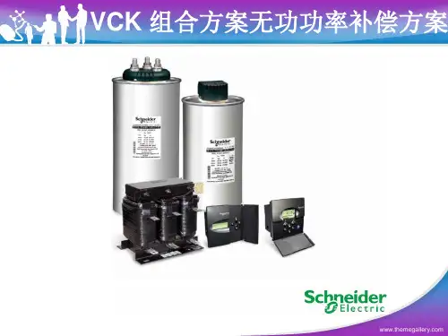
施耐德电气公司的低压无功补偿产品我们用到的主要有Varplus M电容器,Varlogic控制器和LC1-D.K专用电容接触器等。
2.Varplus M1和Varplus M4电容器组合成较大容量电容器时,应遵守的规则如下:⏹M1和M1之间可以组合,M4只能和M1组合,M4之间不可以组合。
⏹M1的组装数量最多为4个,即最大组合为:1xM4+4xM1.⏹230V电容器的最大组装容量为60 kvar,其他电压登记电容器的最大组装容量为100kvar注意:2个M4电容器不能组装在一起。
3. 确定无功补偿的电容器容量按装置的有功功率和功率因数计算:Qc (kvar) = P (kW) x (tanØ-tanØ’)其中tanØ市根据补偿前装置的功率因数cosØ计算而来,tanØ’是根据补偿后的cosØ’换算而来,P为装置的有功功率:Qc为无功电容器容量。
4.确定应该选用标准型,加大型或失谐型电容器.根据电网中谐波污染程度选择电容器设备:⏹Gh/Sn <= 5%,可使用标准型Varplus T电容器⏹5% < Gh/Sn <= 15%,可使用标准型Varplus M电容器⏹15% < Gh/Sn <= 25%,可使用加大型Varplus H电容器,这种电容器能承受谐波冲击⏹25% < Gh/Sn <= 60%,可使用失谐型Varplus DR电容器,这种电容器能承受谐波冲击⏹Gh/Sn > 60%,需要安装滤波装置。
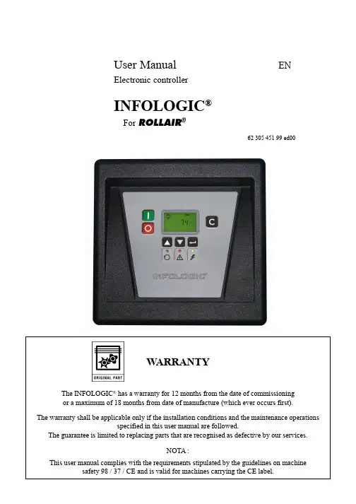
User Manual ENElectronic controllerINFOLOGIC®For ROLLAIR®62 305 451 99 ed00WARRANTYThe INFOLOGIC® has a warranty for 12 months from the date of commissioningor a maximum of 18 months from date of manufacture (which ever occurs first).The warranty shall be applicable only if the installation conditions and the maintenance operationsspecified in this user manual are followed.The guarantee is limited to replacing parts that are recognised as defective by our services.NOTA :This user manual complies with the requirements stipulated by the guidelines on machine safety 98 / 37 / CE and is valid for machines carrying the CE label.06/07 Page 2CONTENTSChapter 1 - Safety Measures (3)SAFETY (3)INSTALLATION (3)QUALIFICATION (3)MAINTENANCE AND REPAIRS (3)EXTERNAL CONTROL (3)Chapter 2 - Introduction (3)2.1 - Control panel (3)2.2 - Introduction (3)2.3 - Autornatic control of the compressor (4)2.4 - Protecting the compressor (4)2.5 - Service waming (4)2.6 - Automatie restart after voltage failure (4)Chapter 3 - INFOLOGIC® regulator (4)3.1 - Control panel (4)3.2 - Display (6)3.3 - Pictographs used on the screen (6)3.4 - Main screen (7)3.5 - Shut-down waming (7)3.5.1 - Description (7)3.5.2 - Compressor element outlet temperature (7)3.5.3 - Dew-point temperature (8)3.6 - Shut-down (8)3.6.1 - Description (8)3.6.2 - Compressor element outlet temperature (9)3.6.3 - Motor overload (9)3.7 - Servioe waming (10)3.7.1 - Description (10)3.8 - Scroiling through all screens (11)3.8.1 - Control panel (11)3.8.2 - Overview of the screens (12)3.9 - Menu flow (13)3.10 - Calling up outiet and dew-point temperatures (14)3.11 - Calling up running hours (15)3.12 - Calling up motor starts (15)3.13 - Calling up module hours (16)3.14 - Calling up loading hours (17)3.15 - Affichage du nombre de mise en charge (17)3.16 - Calling upiresetting service timer (18)3.16.1 - Control panel (18)3.16.2 - Resetting the service tirner (18)3.17 - Selection between local, remote or LAN control (19)3.18 - Calling up modifying node ID for LAN control (19)3.19 - Calling up modifying pressure band settings (20)3.20 - Modifying pressure band selection (21)3.21 - Calling up/modifying service timer setting (22)3.22 - Calling up/modifying unit of temperature (22)3.23 - Calling up/modifying unit of pressure (23)3.24 - Activating automatic restart after voltage failure (23)3.25 - Selection between Y-D or DOL starting (24)3.26 - Calling up modifying load delay time (24)3.27 - Calling up modifying minimum stop time (25)3.28 - Activating password protection (25)3.29 - Calling up modifying protection settings (26)3.30 - Test screens (28)62 305 451 9962 305 451 9906/07Page 3Chapter 1 - Safety MeasuresSAFETYThe personnel using the INFOLOGIC ® shall use safe work practices and respect the local instructions and regulations concerning safety and hygiene.All electrical tests shall be carried out according to the professional rules. Always cut off the electrical power supply before starting any kind of maintenance work.INSTALLATIONThe electrical cabinet should have a free access for facilitating maintenance, the location of INFOLOGIC ® shall allow at any moment the visibility of luminous indicators and the digital display.QUALIFICATIONThe INFOLOGIC ® shall be used only by competent, trained and qualified personnel; the manipulation of parameters can modify the characteristics and the performances of the compressor.MAINTENANCE AND REPAIRSThe works of maintenance and repairs and the configuration of the INFOLOGIC ® can be carried out only by competent and qualified personnel.If spare parts are required, use only the original parts supplied by the manufacturer.EXTERNAL CONTROLThe Stop and Start buttons on the controller are deactivated when the INFOLOGIC ® control is on "remote" or "LAN".To stop the machine with the controller, it must first be placed in Local mode (see § 3.17)Chapter 2 - Introduction2.1 - Control panel2.2 - IntroductionIn general, the INFOLOGIC ® controller has following functions :• Controlling the compressor • Protecting the compressor• Monitoring components subject to, service• Automatic restart after voltage failure (made inactive in the works)162 305 451 9906/07Page 42.3 - Autornatic control of the compressorThe regulator maintains the net pressure between programmable limits by automatically loading and unloading the compressor. A number of programmable settings, e.g. the unloading and loading pressures, the minimum stop time and the maximum number of motor starts are taken into account.The regulator stops the compressor whenever possible to reduce the power consumption and restarts it automatically when the net pressure decreases.2.4 - Protecting the compressorShut-downIf the compressor element outlet temperature exceeds the programmed shut-down level, the compressor will be stopped. This will be indicated on display (1) page 3. The compressor will also be stopped in case of overload of the drive motor.Before remedying, consult the Safety precautions.Shut-down warningA shut-down waming level is a programmable level below the shut-down level.If one of the measurements exceeds the programmed shut-down warning level, this will aiso be indicated to warn the operator before the shut-down level is reached.2.5 - Service wamingIf the service timer exceeds a programmed value, this will be indicated on display (1) page 3 to wam the operator to carry out some service actions.2.6 - Automatie restart after voltage failureThe regulator has a built-in function to automatically restart the compressor when the voltage is restored after voltage failure. This function is deactivated in compressors leaving the factory. If desired, the function can be activated. Consult the consumer service centre.If activated, and provided the regulator was in the automatic operation mode, the compressor will automatically restart when the supply voltage to the module is restored.Chapter 3 - INFOLOGIC ® regulator3.1 - Control panel1231241498761162 305 451 9906/07Page 5FunctionS10Emergency stop buttonPush button to stop the compressorimmediately in the event of an emergency.After remedying the trouble, uniock thebutton by pulling it out and press reset key (4).1Stop button (red)Push button to stop the compressor. LED (10) goes out. The compressor will stop after running in unloaded condition for about 30 seconds.2Start button (green)Push button to start the compressor. LED (10) lights up indicating that the regulator is operative (in automatic operation).3DisplayIndicates the compressor operatingcondition, actually measured values and programmed parameters.4ResetkeyKey to reset the service timer, a shut-down condition, etc or to return to a previous display.5Enter keyKey to select or validate a parameter, to open a sub-display.6V oltage on LED (green)Indicates that the voltage is switched on.7PictographV oltage on.8General alarm LED (red)Is lit if a waming condition exists.8General alarm LED (red)Flashes in the event of a shut-down or emergency stop condition.9PictographAlarm.10Automatic operation LED (green)Indicates that the regulator is automatically controlling the compressor: thecompressor is loaded, unloaded, stopped and restarted depending on the air consumption and the limitations programmed in the regulator.The LED is lit during automatic operation and flashes when the unit is remotely controlled.11PictographAutomatic operation.12Downwards scroll keyKey to scroll downwards through the screens or to decrease a setting.13Upwards scroil keyKey to scroll upwards through the screens or to increase a setting.14PictographRemote operation62 305 451 9906/07Page 63.2 - DisplayDescription• The compressor status by means of pictographs • The actual temperature at the compressor element outlet• The dew-point temperature (for compressors with incorporated dryer option).The display also shows all measured and programmed parameters, see section Scrolling through all screens.3.3 - Pictographs used on the screenCompressor status LOAD (during loaded running, the horizontal arrow flashes).Compressor status UN LOAD.LOAD and UNLOAD indication.162 305 451 9906/07Page 73.4 - Main screenProcedureWhen the voltage is switched on, the Main screen is shown automatically, showing in short the operation status of the compressor and the outlet pressure:Main screen, typical exampleThe screen shows that the compressor is running loaded (the horizontal arrow flashes) and that the outlet pressure is 6.8 bar(e).Also consult section Scrolling through all screens.3.5 - Shut-down waming3.5.1 - DescriptionA shut-down warning will appear in the event of :• Too high a temperature at the outlet of the compressor element• Too high a dew-point temperature for compressors fitted with this option,3.5.2 - Compressor element outlet temperature• If the outlettemperature of the compressorelementexceeds the shut-down warning level (105 °C /221 °F), alarrn LED (4)will light up and the related pictograph will appear fiashing.Main screen with warning element outlet temperature• Press arrow key (3), the actual compressor element temperature appears.Warning screen, element outlet temperature1254362 305 451 9906/07Page 8The screen shows that the temperature at the outlet of the compressor element is 106°C.• It remains possible to scroil through other screens (using keys 3 and 5) to check the actual status of other parameters.• Press button (1) to stop the compressor and wait until the compressor has stopped.• Switch off the voltage, inspect the compressor and remedy.• The warning message will disappear as soon as the warning condition disappears.3.5.3 - Dew-point temperatureFor compressors with integrated dryer:• If the dew-point temperature exceeds the warning level (not programmable), alarrn LED (4) will light up and the related pictograph will appear fiashing.Main screen with warning dew-point temperature• Press arrow key (3) until the actual dew-point temperature appears.Warning screen, element outlet temperatureThe screen shows that the dew-point temperature is 9 °C.• It remains possible to scroll through other screens (using keys 3 and 5) to check the actual status of other parameters.• Press button (1) to stop the compressor and wait until the compressor has stopped.• Switch off the voltage, inspect the compressor and remedy.• The warning message will disappear as soon as the warning condition disappears.3.6 - Shut-down3.6.1 - DescriptionThe compressor will be shut down in case :• The temperature at the outlet of the compressor element exceeds the shut-down level • Of error of the outlet pressure sensor • Of overload of the drive motor62 305 451 9906/07Page 93.6.2 - Compressor element outlet temperatureIf the outlet temperature of the compressorelementexceeds the shut-down level (110 °C/230 °F, programmable) the compressor will be shut-down, alarm LED (4) will flash, automatic operation LED (5) will go out and the following screen will appear:Main screen with shut-down indication, element outlet temperature• Press arrow key (3) until the actual compressor element temperature appears.Shut-down screen, element outlet temperatureThe screen shows that the temperature at the outlet of the compressor element is 111°C.• Switch off the voltage and remedy the trouble.• After remedying and when the shut-down condition has disappeared, switch on the voltage and restart the compressor.3.6.3 - Motor overload• In the event of motor overload, the compressor will be shut-down, alarrn LED (4) will flash, automatic operation LED (5) will go out and the following screen will appear :Main screen with shut-down indication, motor overload• Switch off the voltage and remedy the trouble.• After remedying and when the shut-down condition has disappeared, switch on the voltage and restart the compressor.1254362 305 451 9906/07Page 103.7 - Servioe waming3.7.1 - DescriptionA service warning will appear when the service timer has reached the programmed time interval.• Stop the compressor, switch off the voltage and carry out the service actions. See section Preventive maintenance schedule.• After servicing, reset the service timer. See section Calling up/resetting service timer.3.8 - Scroiling through all screens3.8.1 - Control panelThe screen shows the screen number <d.0 1 >, the unit used <hrs> and the related pictograph for running hours. Press enter key (1) to call up the actual running hours.In the event of a warning or a shut-down, the corresponding pictograph is blinking on the main screen.3.8.2 - Overview of the screens3.9 - Menu flowSimplifted menu flow3.10 - Calling up outiet and dew-point temperaturesControl panelStarting from the Main screen :• Press arrow key (2), the outlet temperature will be shown :The screen shows that the outlet temperature is 83 °C.• Compressor with incorporated dryer option :Press arrow key (2), the dew-point temperature will be shown :The screen shows that the dew-point temperature is 3 °C.• Press arrow keys (2 and 3) to scroil downwards or upwards through the screens.2133.11 - Calling up running hoursControl panelThe screen shows the unit used <xl 000 hrs> and the value < 1 1.25>: the running hours of the compressor are 11250 hours.3.12 - Calling up motor startsControl panel213Starting from the Main screen :• Press arrow key (2) until <d.02> is shown and then press enter key (1) :This screen shows the number of motor starts times 1000 (times 1 or if <xl 000> lits up times 1000). The number of motor starts is 10 100.3.13 - Calling up module hoursControl panelThe screen shows the unit used <hrs> and the value <5000>: the module hours of the compressor are 5000 hours.3.14 - Calling up loading hoursControl panelThe screen shows the unit used <hrs> (or <x1000 hrs> and the value <1755>: the loading hours of the compressor are 1755 hours.3.15 - Affichage du nombre de mise en chargeControl panel213Starting from the Main screen :• Press arrow key (2) until <d.05> is shown and then press enter key (1) :This screen shows the number of unload to load actions (times 1 or if " 1 000> lits up times 1000). The number of unioad to load actions is 10100.3.16 - Calling upiresetting service timer3.16.1 - Control panelThis screen shows the unit used <hrs> (or <xl 000> hours x 1000) and the value < 1191 >: the compressor has run 1191 hours since the previous service.3.16.2 - Resetting the service tirnerAfter servicing, see section Service warning, the timer has to be reset :• Scroli to register screen <d.06> and press enter key (2).• The reading (e.g. 4000) will appear.• Press enter key (2), if a password is set enter the password. The reading will flash (indicating that resetting is possible).• Press enter key (2) to, reset the timer to <0.000> or press reset key (1) to cancel the operation.3.17 - Selection between local, remote or LAN controlControl panel• Press arrow key (2) until <P.01 > is shown and then press enter key (1). The actually used control mode is shown <LOC> for local control, <rE> for remote control or <LAn> for LAN control.• Press enter key (1) and if necessary enter the password. The actually control mode is blinking. Use keys (2) and (3) to change the control mode.• Press enter key (1) to program the new starting mode or press reset key to cancel.3.18 - Calling up modifying node ID for LAN controlControl panel213Starting from the Main screen :• Press arrow key (2) until <P.02> is shown and then press enter key (1). The actually used node ID is shown.• Press enter key (1) and if necessary enter the password. The actually used node ID is blinking. Use keys (2) and (3) to change the node ID.• Press enter key (1) to program the new node ID or press reset key to cancel .3.19 - Calling up modifying pressure band settingsControl panelStarting from the Main screen :• Press arrow key (2) until <P.03> is shown and then press enter key (1). Pressure band 1 <Pb.l> is shown on the display, key (2) can be used to scroll to pressure band 2 <Pb.2>.• Press enter key (1) on desired pressure band. The load level of the selected pressure band appears, key (2) can be used to scroil tothe unload level.Loading pressure213Unloading pressure• Press enter key (1) to modify the load level (value starts blinking). A password may be required. Use keys (2) and (3) to change the load pressure.• Press enter key (1) to program the new values or press reset key to cancel.3.20 - Modifying pressure band selectionControl panel• Press key (2) to modify the active pressure band. Press enter key (1) to, confirm or reset key to cancel.3.21 - Calling up/modifying service timer settingControl panelStarting from the Main screen :• Press arrow key (2) until <P.05> is shown and then press enter key (1) : the setting of the service timer is shown in <hrs> (hours)or <xl000 hrs> (hours x 1000). Example: <4000 hrs> means the timer is set at 4000 running hours.• Press enter key (1) to modify this value (a password may be required), the value blinks. Use arrow keys (2 and 3) to modify this setting.• Press enter key (1) to program the new value and to retum to the parameter screens.3.22 - Calling up/modifying unit of temperatureControl panel213213Starting from the Main screen :• Press arrow key (2) until <P.06> is shown and then press enter key (1). The possible settings are: <°C> and <°F>; the actually used unit is shown.• Appuyer sur la touche Entrée (1) (l'unité clignote), puis utiliser les touches fléchées (2 et 3) pour sélectionner une unité de température différente.• Appuyer sur la touche Entrée (1) pour programmer la nouvelle unité, puis appuyer sur la touche de réarmement pour revenir aux écrans de paramètres.3.23 - Calling up/modifying unit of pressureControl panelStarting from the Main screen :• Press arrow key (2) until <P.O> and the possible settings are shown <Mpa>, <psi>, and <bar>, press enter key (1) and the actually used unit is shown.• Press enter key (1) (unit starts blinking) and use arrow keys (2 and 3) to select another unit of pressure.• Press enter key (1) to program the new unit of pressure and press reset key to return to, the parameter screens.3.24 - Activating automatic restart after voltage failureDescriptionThis parameter, accessible in screen <P.08>, can only be modified after entering a code. Consult us if this function should be activated.2133.25 - Selection between Y-D or DOL startingControl panelStarting from the Main screen :• Press arrow key (2) until <P.09> and the motor pictograph is shown and then press enter key (1). The actually used starting mode is shown <Y-d> for Y-D (star-delta) or <doL> for DOL (direct-on line).• This parameter can only be modified after entering a code. Consult us if the parameter is to be changed.3.26 - Calling up modifying load delay timeControl panelStarting from the Main screen :• Press arrow key (2) until <P.10> and the compressorload pictograph is shown and then press enter key (1) :213213• This screen shows the load delay time 10 and the unit <s> seconds. To modify this value press enter key (1).• An optional password may be required, the value starts blinking and arrow keys (2) and (3) can be used to modify the value.• Press enter key (1) to prograrn the new value, press reset key to cancel.3.27 - Calling up modifying minimum stop timeControl panelStarting from the Main screen :• Press arrow key (2) until <P.11> and the motor pictograph is shown and then press enter key (1) :• This screen shows the minimum stop time 10 and the unit <s> seconds. To modify this value press enter key (1).• The value starts blinking and arrow keys (2) and (3) can be used to modify this value.• Press enter key (1) to program the new value.3.28 - Activating password protectionControl panelImportant settings such as the setting of the service timer, pressure band setting, control mode settings,... can be protected by a password.213Starting from the Main screen :• Press arrow key (2) until <P.12> and press enter key (1) :213213A number of protection settings are provided. The protection screens are numbered <Pr.>, the pictograph shown with the protection screen indicates the purpose of the protection.Possible combinations are <Pr.> followed by a number and one of the next pictographs :Four protection settings are possible :• A low waming level shown on the display as <AL-L>.• A high waming level shown on the display as <AL-H>.• A low shut-down level shown on the display as <Sd-L>.• A high shut-down level shown on the display as <Sd-H>Example of protection screen• The warning level for the high temperature waming level <AL-H> and the high temperature shut-down level <Sd-H>. Use scroll keys (2 and 3) from the waming level to the shut-down level, press enter key (1) to modify the value • The value appears on the display.• Press enter key (1) to modify the value.• An optional password may be required, the value starts blinking and arrow keys (2) and (3) can be use to modify the value.• Press enter key (1) to program the new value, press reset key to cancel.3.30 - Test screensDisplay test• Press arrow key (2) until <t.01> is shown and then press enter key (1) :Safety valve testIn the test screen <.02> a safety valve test is provided. The safety valves can only be tested after entering a code.Consult us if the safety valves are to be tested.NOTES。
NR6/12无功补偿控制器使用说明1.对照接线图检查柜内接线:如下图2.检查各个连接端子的连接:注意检查端子有无接插不牢,虚接,掉线及漏线等现象!3.控制器上电:确认接线和连接状态正常后,给控制器接上额定工作电压;当控制器第一次上电时,控制器液晶显示为:按进入语言选择,通过和选择英语(ENGLISH).当控制器为非第一次上电时,通电后屏幕显示为测量值。
注:当控制器屏幕显示字母与本文不一致时,有可能是语言设置错误,建议参考本文第7条进行语言设定。
4.进入主菜单当控制器第一次上电并设置完语言选项后,直接进入主菜单此时屏幕显示为:当控制器为非第一次上电时,通电后屏幕显示为测量值,此时按下或 2秒后进入主菜单,此时屏幕显示为:5.手动设置A进入:通过和,当屏幕显示为,按进入,屏幕显示为,同时按下和 2秒,屏幕显示为:;B CT 变比设置:按下进入变比设置,通过和,设置CT变比,设置完毕后按;C 额定电压设置:设置完CT变比后,屏幕显示为:,按下进入额定电压设置,通过和,设置额定电压,设置完毕后按;D 接线方式设置:设置完额定电压后,屏幕显示为:,按下进入接线方式设置,先进行电压接线设置,显示选项分别为:U.L2-L3、U.L3-L1、U.L1-L2、U.L1-N、U.L2-N、U.L3-N, 通过和选择与实际电压接线一致的选项,按下;此时进入电流接线设置,显示选项为:I.1 DIR、I.1 REV、I.1 AUTO、I.2 DIR、I.2 REV、I.2 AUTO、I.3 DIR、I.3 REV、I.3AUTO, 通过和选择与实际电流接线一致的选项,按下;注:电流极性选择:DIR=直接连接,REV=反向连接,AUTO=自动极性选择(控制器定义);电流设置一般设置为AUTO。
E 目标功率因数设置:设置完接线方式后,屏幕显示为:,按下进入目标功率因数设置通过和,设定功率因数,设置完毕后按;F 手动响应值(C/K)设定:设置完目标功率因数后,屏幕显示为:,按下进入响应值(C/K)设置通过和设定响应值(C/K),按下;注:响应值(C/K)表:CK 值表-AC400V系统当响应值在表中查不到时请按响应值计算公式进行计算:G 投切延时设定:设定完响应值(C/K)数后,屏幕显示为:,按下进入投切延时设置通过和设定延时时间,按下;注:建议投切延时时间为60秒以上H 投切程序设定:设定完投切延时后,屏幕显示为:,按下进入投切程序选择,通过和设定选择响应的投切程序,按下;注:进入投切程序设定有以下投切程序供选择:NORMAL: 适用于电容器容量比为:1,2,4,4…前两步为调整步;CIRC.A:适用于电容器容量比为:1,1,1,1…投切逻辑为“先进先出”;CIRC.B:适用于电容器容量比为:1,2,2,2…第一步为调整步;STACK:适用于电容器容量比为:1,1,1,1…投切逻辑为“后进先出”;OPTIM:适用于以下多种电容量比:通过在最短时间内投入最少电容组步数来达到目标功率因数。
施耐德电气技术答疑系列大全之十四341,问:开关粘合、不能开或关,为什么?原因:开关静触头与动触头之间,因开关在闭合和断开的瞬间,会产生电火花,如果触点所选用的材料不符合要求(品质不佳)或开关动作迟缓,开关使用一段时间后,电火花产品的高温,会造成静触头与动触头熔焊在一起,故有开关粘合,不能开或关现象。
342,问:带开关二、三极插座(U570)与分体带开关二、三极插座(U575)有什么区别?带开关二、三极插座(U570),其上的指甲型开关可控制插座是否带电。
开关ON插座带电,开关OFF插座没电。
分体带开关二、三极插座(U575),可以与U570的功能相同。
还可以插座、开关各自独立使用。
指甲型开关独立控制其他回路,比如作为灯开关使用。
343,问:全自动红外线感应开关(U410)与红外感应带消防保护开关(U415)有什么区别?红外感应开关(U410),利用红外线技术控制原理进行全自动控制。
当光线较暗时,专用传感器探测到人体红外光谱的变化,开关自动接通负载并延时到设定时间;当光亮度足够时,自动抑制接通;做到人到灯亮,人离灯熄。
红外感应带消防保护开关(U415),正常工作时,与U410的功能相同。
当发生火灾事故时,消防回路发个脉冲信号,则U415所带负载回路强制性带电,灯长亮。
344,问:何为“带一分支一位的电视插座”?“带一分支的电视插座”的正面和”一位电视插座”相同;其主要区别在背面,”带一分支一位的电视插座”有两个铜轴电缆电缆的端子分别标注为:“IN”、“OUT”即可在背面提供一个TV分接口输出,而” 一位电视插座”背后只有一个端子。
345,问:U575面板开关有哪些功能如果在面板背后先做串联连接,后接电源,此时相当于U570,此开关可以控制该插座如果在面板背后分别连接不同电源和负载,则该开关可以控制外面所连负载,对该面板上的插座没有控制作用346,问:订购2P的NS断路器有哪些注意事项?有二种2P的NS断路器,一种是3P框架2P分断极的NS100~250N(仅有N型),其所配热磁脱扣单元Ir可调,Im在In=200A、250A时可调,200A以下时不可调。
Varlogic NR6、NR12功率因数控制器
用户手册
3
5/11××=LL st
U A I Q K C
施耐德电气(中国)投资有限公司
施耐德电气(中国)投资有限公司北京市朝阳区望京东路6号施耐德电气大厦邮编:100102 电话:(010) 84346699 传真:(010) 84501130■上海分公司上海市漕河泾开发区宜山路1009号创新大厦第12层,15层,16层邮编:200233 电话:(021) 2401 2500 传真:(021) 6495 7301■张江办事处上海市浦东新区龙东大道3000号8号楼5楼邮编:201203 电话:(021) 38954699 传真:(021) 58963962 ■广州分公司广州市珠江新城临江大道3号发展中心大厦25层邮编:510623 电话:(020) 85185188 传真:(020) 85185195■武汉分公司武汉市汉口建设大道568号新世界国贸大厦I 座37层01、02、03、05单元邮编:430022 电话:(027) 68850668 传真:(027) 68850488■成都分公司成都市高新技术开发区高棚东路11号邮编:610041 电话:(028) 85178879 传真:(028) 85178717■天津办事处天津市河东区十一经路78号万隆太平洋大厦1401-1404室邮编:300171 电话:(022) 84180888 传真:(022) 84180222■济南办事处济南市泺源大街229号金龙中心主楼21层D室邮编:250012 电话:(0531) 8167 8100 传真:(0531) 86121628■青岛办事处青岛崂山区秦岭路18号青岛国展财富中心二号楼四层413室邮编:266061 电话:(0532) 85793001 传真:(0532) 85793002■石家庄办事处石家庄市中山东路303号世贸皇冠酒店办公楼12层1201室邮编:050011 电话:(0311) 86698713 传真:(0311) 86698723■沈阳办事处沈河区青年大街219号华新国际大厦16层F/G/H/I座邮编:110016 电话:(024) 23964339 传真:(024) 23964296/97■哈尔滨办事处哈尔滨南岗区红军街15号奥威斯发展大厦22层A, B座邮编:150001 电话:(0451) 53009797 传真:(0451)53009639/40■长春办事处长春解放大路 2677号长春光大银行大厦1211-12室邮编:130061 电话:(0431) 88400302/03传真:(0431) 88400301■大连办事处大连沙河口区五一路267号17号楼201-I室邮编:116023 电话:(0411) 84769100 传真:(0411) 84769511■西安办事处西安高新区科技路48号创业广场B座17层1706室邮编:710075 电话:(029) 88332711 传真:(029) 88324697/4820■太原办事处太原市府西街268号力鸿大厦B区1003室邮编:030002 电话:(0351) 4937186 传真:(0351) 4937029■乌鲁木齐办事处乌鲁木齐市新华北路5号美丽华酒店A座2521室邮编:830002 电话:(0991) 2825888 ext. 2521传真:(0991) 2848188■南京办事处南京市中山路268号汇杰广场2001-2003室邮编: 210008 电话:(025) 83198399 传真:(025) 83198321■苏州办事处苏州市工业园区苏华路2号国际大厦1711-1712室邮编:215021 电话:(0512) 68622550 传真:(0512) 68622620■无锡办事处无锡市太湖广场永和路28号无锡工商综合大楼17层邮编:214021 电话:(0510) 81009780 传真:(0510) 81009760■南通办事处江苏省南通市工农路111号华辰大厦A座1103室邮编:226000 电话:(0513) 85228138 传真:(0513) 85228134■常州办事处常州市局前街2号常州椿庭楼宾馆1216室邮编:213000 电话:(0519) 8130710 传真:(0519) 8130711
■合肥办事处合肥市长江东路1104号古井假日酒店820房间邮编:230011 电话:(0551) 4291993 传真:(0551) 2206956■杭州办事处杭州市滨江区江南大道588号恒鑫大厦10楼邮编:310053 电话:(0571) 89825800 传真:(0571) 85825801■南昌办事处江西南昌市八一大道357号财富广场2701室邮编:330003 电话:(0791) 6272972 传真:(0791) 6295323■福州办事处福州市仓山区建新镇闽江大道169号水乡温泉住宅区二期29号楼102单元邮编:350000 电话:(0591) 87114853 传真:(0591) 87112046■洛阳办事处洛阳市涧西区凯旋西路88号华阳广场国际大饭店609室邮编:471003 电话:(0379) 65588678 传真:(0379) 65588679■厦门办事处厦门市思明区厦禾路189号银行中心2502-03A室邮编:361003 电话:(0592) 2386700 传真:(0592) 2386701■宁波办事处宁波市江东北路1号宁波中信国际大酒店833室邮编:315010 电话:(0574) 87706808 传真:(0574) 87717043■温州办事处温州市车站大道高联大厦写字楼9层B2号邮编:325000 电话:(0577) 86072225/6/7/9 传真:(0577) 86072228■成都办事处成都市科华北路62号力宝大厦22楼1.2.3.5单元邮编:610041 电话:(028) 66853777 传真:(028) 66853778■重庆办事处重庆市渝中区邹容路68号重庆大都会商厦12楼1211-12室邮编:400010 电话:(023) 63839700 传真:(023) 63839707■佛山办事处佛山市祖庙路33号百花广场26层2622-2623室邮编:528000 电话:(0757) 83990312/0029/1312传真:(0757) 83991312■昆明办事处昆明市三市街6号柏联广场10楼07-08单元邮编:650021 电话:(0871) 3647549 传真:(0871) 3647552■长沙办事处长沙市劳动西路215号湖南佳程酒店14层01, 10, 11室邮编:410011 电话:(0731) 85112588 传真:(0731) 85159730■郑州办事处郑州市金水路115号中州皇冠假日酒店C座西翼2层邮编:450003 电话:(0371) 6593 9211 传真:(0371) 6593 9213■泰州办事处江苏省泰州市青年南路39号新永泰大酒店8512房间邮编:225300 电话:(0523) 86397849 传真:(0523) 86397847■中山办事处中山市中山三路18号中银大厦18楼1813室邮编:528403 电话:(0760) 8235971 传真:(0760) 8235979■鞍山办事处鞍山市铁东区南胜利路21号万科写字楼2009室邮编:114001 电话:(0412) 5575511/5522传真:(0412) 5573311
■烟台办事处烟台市南大街9号金都大厦2516室邮编:264001 电话:(0535) 3393899 传真:(0535) 3393998■扬中办事处扬中市前进北路52号扬中宾馆2018号房间邮编:212000 电话:(0511) 88398528 传真:(0511) 88398538■南宁办事处南宁市南湖区民族大道111号广西发展大厦12层邮编:530000 电话:(0771) 5519761/9762传真:(0771) 5519760■东莞办事处东莞市南城区体育路2号鸿禧中心A406单元邮编:523070 电话:(0769) 22413010 传真:(0769) 22413160■深圳办事处深圳市罗湖区深南东路5047号深圳发展银行大厦17层H-I室邮编:518001 电话:(0755) 25841022 传真:(0755) 82080250■贵阳办事处贵阳市中华南路49号贵航大厦1204室邮编:550003 电话:(0851) 5887006 传真:(0851) 5887009■海口办事处海南省海口市文华路18号的海南文华大酒店的第六层 607室邮编:570305 电话:(0898) 6859 7287 传真:(0898) 6859 7295
■施耐德电气中国研修学院北京市朝阳区望京东路6号施耐德电气大厦邮编:100102 电话:(010) 84346699 传真:(010) 84501130
SCDOC798-LV 2010.03施耐德电气中国版权所有施耐德电气中国
Schneider Electric China
北京市朝阳区望京东路6号施耐德电气大厦邮编: 100102
电话: (010) 8434 6699
传真: (010) 8450 1130Schneider Electric Building, No. 6, East WangJing Rd., Chaoyang District Beijing 100102 P.R.C.Tel: (010) 8434 6699Fax: (010) 8450 1130本手册采用生态纸印刷
由于标准和材料的变更,文中所述特性和本资料中的图像只有经过我们的业务部门确认以后,才对我们有约束。
客户关爱中心热线:400 810 1315。