电力电子英文文献1
- 格式:pdf
- 大小:1.21 MB
- 文档页数:2
电力电子方向国际期刊介绍电力电子是电气工程的重要分支领域之一,涉及到电力系统中的电力转换、控制和传输等方面的技术研究。
在这个领域中,有许多国际期刊涵盖了电力电子方向的相关研究成果和学术进展。
本文将介绍其中几个重要的国际期刊。
1. IEEE Transactions on Power Electronics(影响因子:9.237):IEEE Transactions on Power Electronics(简称TPEL)是电力电子领域最权威的期刊之一、该期刊发表电力电子技术、应用和相关领域的原创研究论文。
主题涵盖了功率电子器件、功率电子转换器、电力电子控制、电力电子应用等。
2. IEEE Journal of Emerging and Selected Topics in Power Electronics(影响因子:7.424):IEEE Journal of Emerging and Selected Topics in Power Electronics(简称JESTPE)关注电力电子领域中的新兴技术和选择性话题。
该期刊主要涵盖了新兴电力电子器件、新型电力电子拓扑结构、能量转换和传输等方面的研究。
3. IEEE Power Electronics Letters(影响因子:3.896):IEEE Power Electronics Letters(简称PEL)是电力电子领域的快速通信期刊。
该期刊专注于电力电子的创新技术、应用案例和各种重要问题的解决方案。
论文范围包括功率器件、拓扑结构、控制方法、系统集成等。
4. IET Power Electronics(影响因子:3.166):IET Power Electronics是国际能源工程技术学会(IET)旗下的一本期刊。
该期刊发表关于电力电子和其应用的高质量研究论文。
主题范围包括电力转换器、功率器件、开关电源、电力电子应用等。
5. Journal of Power Electronics(影响因子:2.270):Journal of Power Electronics(简称JPE)是韩国电机工程师协会(KIEE)主办的一本期刊。
外文出处:Farhadi, A. (2008). Modeling, simulation, and reduction of conducted electromagnetic interference due to a pwm buck type switching power supply. Harmonics and Quality of Power, 2008. ICHQP 2008. 13th International Conference on, 1 - 6.Modeling, Simulation, and Reduction of Conducted Electromagnetic Interference Due to a PWM Buck Type Switching Power Supply IA. FarhadiAbstract:Undesired generation of radiated or conducted energy in electrical systems is called Electromagnetic Interference (EMI). High speed switching frequency in power electronics converters especially in switching power supplies improves efficiency but leads to EMI. Different kind of conducted interference, EMI regulations and conducted EMI measurement are introduced in this paper. Compliancy with national or international regulation is called Electromagnetic Compatibility (EMC). Power electronic systems producers must regard EMC. Modeling and simulation is the first step of EMC evaluation. EMI simulation results due to a PWM Buck type switching power supply are presented in this paper. To improve EMC, some techniques are introduced and their effectiveness proved by simulation.Index Terms:Conducted, EMC, EMI, LISN, Switching SupplyI. INTRODUCTIONFAST semiconductors make it possible to have high speed and high frequency switching in power electronics []1. High speed switching causes weight and volume reduction of equipment, but some unwanted effects such as radio frequency interference appeared []2. Compliance with electromagnetic compatibility (EMC) regulations is necessary for producers to present their products to the markets. It is important to take EMC aspects already in design phase []3. Modeling and simulation is the most effective tool to analyze EMC consideration before developing the products. A lot of the previous studies concerned the low frequency analysis of power electronics components []4[]5. Different types of power electronics converters are capable to be considered as source of EMI. They could propagate the EMI in both radiated and conducted forms. Line Impedance Stabilization Network (LISN) is required for measurement and calculation of conducted interference level []6. Interference spectrum at the output of LISN is introduced as the EMC evaluation criterion []7[]8. National or international regulations are the references forthe evaluation of equipment in point of view of EMC []7[]8.II. SOURCE, PATH AND VICTIM OF EMIUndesired voltage or current is called interference and their cause is called interference source. In this paper a high-speed switching power supply is the source of interference.Interference propagated by radiation in area around of an interference source or by conduction through common cabling or wiring connections. In this study conducted emission is considered only. Equipment such as computers, receivers, amplifiers, industrial controllers, etc that are exposed to interference corruption are called victims. The common connections of elements, source lines and cabling provide paths for conducted noise or interference. Electromagnetic conducted interference has two components as differential mode and common mode []9.A. Differential mode conducted interferenceThis mode is related to the noise that is imposed between different lines of a test circuit by a noise source. Related current path is shown in Fig. 1 []9. The interference source, path impedances, differential mode current and load impedance are also shown in Fig. 1.B. Common mode conducted interferenceCommon mode noise or interference could appear and impose between the lines, cables or connections and common ground. Any leakage current between load and common ground couldbe modeled by interference voltage source.Fig. 2 demonstrates the common mode interference source, common mode currents Iandcm1 and the related current paths[]9.The power electronics converters perform as noise source Icm2between lines of the supply network. In this study differential mode of conducted interference is particularly important and discussion will be continued considering this mode only.III. ELECTROMAGNETIC COMPATIBILITY REGULATIONS Application of electrical equipment especially static power electronic converters in different equipment is increasing more and more. As mentioned before, power electronics converters are considered as an important source of electromagnetic interference and have corrupting effects on the electric networks []2. High level of pollution resulting from various disturbances reduces the quality of power in electric networks. On the other side some residential, commercial and especially medical consumers are so sensitive to power system disturbances including voltage and frequency variations. The best solution to reduce corruption and improve power quality is complying national or international EMC regulations. CISPR, IEC, FCC and VDE are among the most famous organizations from Europe, USA and Germany who are responsible for determining and publishing the most important EMC regulations. IEC and VDE requirement and limitations on conducted emission are shown in Fig. 3 and Fig. 4 []7[]9.For different groups of consumers different classes of regulations could be complied. Class Afor common consumers and class B with more hard limitations for special consumers are separated in Fig. 3 and Fig. 4. Frequency range of limitation is different for IEC and VDE that are 150 kHz up to 30 MHz and 10 kHz up to 30 MHz respectively. Compliance of regulations is evaluated by comparison of measured or calculated conducted interference level in the mentioned frequency range with the stated requirements in regulations. In united European community compliance of regulation is mandatory and products must have certified label to show covering of requirements []8.IV. ELECTROMAGNETIC CONDUCTED INTERFERENCE MEASUREMENTA. Line Impedance Stabilization Network (LISN)1-Providing a low impedance path to transfer power from source to power electronics converter and load.2-Providing a low impedance path from interference source, here power electronics converter, to measurement port.Variation of LISN impedance versus frequency with the mentioned topology is presented inFig. 7. LISN has stabilized impedance in the range of conducted EMI measurement []7.Variation of level of signal at the output of LISN versus frequency is the spectrum of interference. The electromagnetic compatibility of a system can be evaluated by comparison of its interference spectrum with the standard limitations. The level of signal at the output of LISN in frequency range 10 kHz up to 30 MHz or 150 kHz up to 30 MHz is criterion of compatibility and should be under the standard limitations. In practical situations, the LISN output is connected to a spectrum analyzer and interference measurement is carried out. But for modeling and simulation purposes, the LISN output spectrum is calculated using appropriate software.基于压降型PWM开关电源的建模、仿真和减少传导性电磁干扰摘要:电子设备之中杂乱的辐射或者能量叫做电磁干扰(EMI)。
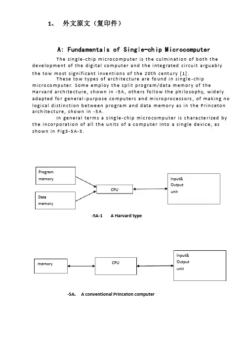
1、 外文原文(复印件)A: Fundamentals of Single-chip MicrocomputerT h e sin gle -ch ip mi c ro co m p u t e r is t h e cu lm in at io n of b ot h t h e d e ve lo p me nt of t h e d ig ita l co m p u t e r a n d t h e i nte g rated c ircu it a rgu ab l y t h e to w mo st s ign if i cant i nve nt i o n s of t h e 20t h c e nt u ry [1].T h ese to w t yp e s of arch ite ct u re are fo u n d in s in gle -ch ip m i cro co m p u te r. S o m e e mp l oy t h e sp l it p ro gra m /d at a m e m o r y of t h e H a r va rd arch ite ct u re , s h o wn in -5A , ot h e rs fo l lo w t h e p h i lo so p hy, wid e l y ad a p ted fo r ge n e ral -p u rp o se co m p u te rs an d m i cro p ro ce ss o rs , of m a kin g n o l o g i ca l d i st in ct i o n b et we e n p ro gra m an d d ata m e m o r y as in t h e P rin c eto n a rch ite ct u re , sh o wn in -5A.In ge n e ra l te r m s a s in g le -ch ip m ic ro co m p u t e r is ch a ra cte r ized b y t h e in co r p o rat io n of all t h e u n its of a co mp u te r into a s in gle d e vi ce , as s h o w n in F i g3-5A-3.-5A-1A Harvard type-5A. A conventional Princeton computerProgrammemory Datamemory CPU Input& Output unitmemoryCPU Input& Output unitResetInterruptsPowerFig3-5A-3. Principal features of a microcomputerRead only memory (ROM).RO M is u su a l l y fo r t h e p e r m an e nt , n o n -vo lat i le sto rage of an ap p l i cat io n s p ro g ram .M a ny m i c ro co m p u te rs a n d m i cro co nt ro l le rs are inte n d ed fo r h i gh -vo lu m e ap p l i cat io n s a n d h e n ce t h e e co n o m i cal man u fa c t u re of t h e d e vi ces re q u ires t h at t h e co nt e nts of t h e p ro gra m me mo r y b e co mm i ed p e r m a n e nt l y d u r in g t h e m a n u fa ct u re of c h ip s . C lea rl y, t h i s imp l ies a r i go ro u s ap p ro a ch to ROM co d e d e ve lo p m e nt s in ce ch an ges can n o t b e mad e af te r m an u fa ct u re .T h i s d e ve l o p m e nt p ro ces s m ay i nvo l ve e mu l at i o n u sin g a so p h ist icated d e ve lo p m e nt syste m wit h a h ard wa re e mu l at i o n capab i l it y as we ll as t h e u s e of p o we rf u l sof t war e to o l s.So m e m an u fa ct u re rs p ro vi d e ad d it i o n a l ROM o p t io n s b y in clu d in g in t h e i r ran ge d e v ic es w it h (o r inte n d ed fo r u s e wit h ) u se r p ro g ram m a b le m e mo r y. T h e s im p lest of t h e se i s u su a l l y d e v i ce wh i ch can o p e rat e in a m i cro p ro ce s so r mo d e b y u s in g s o m e of t h e in p u t /o u t p u t l in es as an ad d res s a n d d ata b u s fo r a cc es sin g exte rn a l m e m o r y. T h is t yp e o f d e vi ce can b e h ave f u n ct i o n al l y as t h e s in gle ch ip m i cro co m p u t e r f ro m wh i ch it i s d e ri ved a lb e it wit h re st r icted I/O an d a m o d if ied exte rn a l c ircu it. T h e u s e of t h e se RO M le ss d e vi ces i s co mmo n e ve n in p ro d u ct io n circu i ts wh e re t h e vo lu m e d o e s n ot ju st if y t h e d e ve lo p m e nt co sts of cu sto m o n -ch ip ROM [2];t h e re ca n st i ll b e a si gn if i cant sav in g in I/O an d o t h e r ch ip s co m pared to a External Timing components System clock Timer/ Counter Serial I/O Prarallel I/O RAM ROMCPUco nve nt io n al m i c ro p ro ces so r b ased circ u it. M o re exa ct re p l a ce m e nt fo rRO M d e v ice s can b e o b tain ed in t h e fo rm of va ria nts w it h 'p i g g y-b a c k'E P ROM(E rasab le p ro gramm ab le ROM )s o cket s o r d e v ice s w it h E P ROMin stead of ROM 。
电子电路外文文献外文原文From CHARLES A(HOLT .ELECTRONIC CIRCUITS Digital and Analog.1.1 Basic amplifierStudies the amplifier, we first analyze the circuit of the chart 12—1, it contains abias in the enlargement area NPN transistor. Although base sector width W is the collector voltage function, but in order to cause the discussion to simplify as far as possible, will neglect this secondary effect. Therefore, I and aregard as the ESFconstant. MarkIn here as well as in entire this book, uses the standard symbolic representation electric current and the voltage. The electric current is i is i=I+i BBBb(12-1)When Vfor zero, chart 12—1 electric circuit is called the static state, namely is at ithe dormant state, the static base current is I;when V is not the zero, difference of Bijoint current i and the quiescent value is i. Mark i expresses the increase electric Bbbcurrent, also is called i signal component. Attention: i,I,ithe custom bB B breference direction take flows in the component the B end as.Vexpression from base extremely B to emitter electrode E loss of voltage, BEsimilarly wrote it quiescent voltage V and sum of the increase voltage V. Chart in BEbe12—1 electric circuit V is V. In brief, the lowercase letter raises writes the subscript beito express various joint currents and the total voltage; The capital letter raises writes the subscript to express various static quantity; The lowercase letter belt small letter subscript uses in various increases variable. Stated not specially that, the electric current reference direction take flows in the component as. The voltage reference direction uses the double subscript, when or attempts in likely 12—l Vo such with thepositive and negative symbolic representation, then Q voltage and the electric current refer to the static quantity.Chart 1.1 the amplifier14th chapter operational amplifierExcept that preceding flees has discussed altogether shoots, altogether the collection and altogether outside the base electric circuit, but also has another kind of specially important basic configuration, this is the differential amplifier. It has two signal voltage to input Swiss and an in proportion to input signalinterpolation output. Frequently, from provides the negative feedback in the bleeder network to withdraw the output a part of achievement input voltage; But sometimes, an input end sweet and crisp earth. In these two kinds of situations, the differential amplifier all turns only then an input and an output single end amplifier.We will see to, the differential amplifier might process the big signal but not to have the oversized nonlinear distortion, moreover this big dynamic range will be one of its multitudinous characteristics. Because bias not big time input impedance for center to high impedance, therefore the supply oscillator load cannot be overweight. In the low frequency work (including direct current) is possible. Its electriccircuit structure suits the sub-integrated circuit manufacture specially, thus the most linear integrated circuit contains level or the multistage differential amplifier. This kind of electric circuit example includes: The analog computer network, the monolithic voltage - stabilizer, the video amplifier, simulate the comparator and the operational amplifier. And following several deaf center enlarges in this chapter the operation 2E multi-purpose and the versatility does the key point is correct.The operational amplifier is has the difference input level the multistage structure, its characteristic for the voltage gain big, the input impedance high and the output impedance is low. It widely uses in many different types linearity and in the nonlinear circuit. Using involves to the measuring appliance electric circuit, the special use linear amplifier, the oscillator, has the clothing filter and other electric circuits. In fact, every request is inexpensive voltage amplification situation, all should consider uses the operational amplifier.This chapter studies the operational amplifier some basic characteristics, certain applications also including. Other questions then proposed in the following several chapters. Shows in 15 chapter and in 17 chapter and succinctly discusses three kind of different operational amplifiers the electric circuit, let us from thedifferential amplifier start study.2 Differential amplifierEmitter coupling amplifierHas each kind of type the differential amplifier. The commonelectric circuit structure is arranges two BJT emitter electrode the increase series. Solid illustration in chart 14—1 a. The ideal current supply provides constant direct current Idc in this electric circuit. Therefore, to emitter current increase ingredient ideal current supply for leads the way. Its increase electric circuit has chart 14—1b the form. In the chart,the ideal direct current potential source and the current supply have used to short-circuit and to lead the way separately the substitution. Obviously i,-i. The e1e2amplifier speaking of the increase electric current two emitter electrodes to connect (like chart 14—1 b two emitter electrodes such), is called the emitter coupling amplifier.More importantly transistor Q and Q must pair as far as possible, causes their 12characteristic nearly in to be consistent. When the transistor pair with the input voltage is a zero hour, two transistors collecting electrode electric currents are same. Comes from the electric circuit symmetry to see this is obvious. Even if abbreviates the Q collection electricity level resistance, two electric currents almost are also 1 equal, because works in the enlargement area BJT collecting electrode electric currenthas nothing to do with nearly with V. Thereupon, this resistance is sometimes CEabbreviated. Retains it’s goal to lie in improvement direct current to be balanced. In the increase model, (its function the resistance which just like current supply) connects does not have what influence with the high impedance collecting electrode.Input end A and B are Q and the Q base extreme. The increase model regarding 12the small signal is linear, may apply the principle of superposition. Therefore, inputs us to two to be possible to process separately. Make V = 0, to this kind of situation, S2The increase electric circuit may draw becomes the two-poleamplifier the form,chart 2.1.2 emitter coupling amplifierchart 2.1.3 increase modelLike chart 14—2 show. Just like front had pointed out, the firstlevel of Rc influence may neglect. Obviously this level is approximateis altogether the collection configuration, but second level then is altogether the base. This cascade input impedance is has same r and the r value altogether shoots the amplifier input sximpedance two times.So long as the load resistance is smaller than r, in altogether collection and oaltogether in base two kinds of amplifier when to transmission may suddenly bribery resistance r and r. Makes the load by altogether the ground level low input μoimpedance altogether the collection level obviously to satisfy this request. Because load resistance Rc is usually actual electric circuit in r to be much smaller than, otherefore the common base also satisfies this request. When V = 0, joins V, the s1s2situation is similar. The output voltage then may from no matter what a collecting electrode obtains. In fact, we will see to, in two collecting electrodes resistances increase voltage scope equal but the mark will be opposite. Therefore, the following will analyze neglects with the base sector width modulation related parameter.When supply oscillator resistance Radds to the electric circuit, among sfrequency band increase model like chart 14—3 show. Supposes two transistors ispairs, and has the same quiescent point and the increase parameter. Each collecting electrode resistance R and the collecting electrode increase current supply connects. cTherefore, these resistances do not affect the electric circuit the electric current. Further said, if removes a resistance, does not changein addition in the resistance voltage. Indicates i,i in the emitter electrode pitch point node equation. Obviously, l2two output voltages scope equal but the mark is opposite.Bad mold voltage gain and altogether mold voltage gainExternal circuits return route equations obtain by chart 2.1.2Output voltage V,βRi,Bad mold voltage gain A defines difference of as the ooc2doutput voltage and two input voltages ratio, namelychart 2.1.4 among frequency band model′Outputs V is the V negative value. According to 16—5 center discussion, this kind ooof amplifier may serve as the phase-splitter. Each output all in proportion to two inputs miss V——V. This interpolation is called difference mold input voltage V, s1s2dnamelyTwo input voltages mean value is 1/2, represents altogether mold input voltage V, cThereforeWhen two input voltages are altogether the mold increase by this equal output voltage ratio of with altogether the mold input voltage Ac Regarding chart 14—3 electric circuits, when two input voltages equal output voltage is the zero, thus altogether the mold gain is the zero.So long as application chart 2.2.3 simplifications models, even if two transistors do not pair, altogether the mold increases also is a zero. To this kind of situation, may prove the electric current by the node equation: i and i each other has the direct ratio, 12 thus works as two input voltages equal time two electric currentsare the zero inevitably. However, if includes base sector width modulation resistance rand r, is o μeasy to prove to transistor which has not paired, usual A is not a zero. Therefore, calthough these resistances increase to the difference mold the influence may neglect, when calculates A, in the model must include r and r. Chart 14—3 models coμincluding have not provided the static state emitter current the actual power source increase resistance. This resistance very is usually big, increases when the determination difference mold may neglect it. But in determined when A, it is cpossibly important. Even regarding the transistor which pairs, this resistance appears when the model, all can cause A is not the zero. When low frequency, the A value ccmay be possible negative.Difference of because of the request output in proportion to two inputs, therefore works as two inputs equal time outputs must be minimum. When ideal A should be a czero. An important quality factor is altogether the mold rejection ratio (CMRR), it defines as orUses the full symmetry the electric circuit, uses the transistorwhich pairs and has the very high increase resistance the direct current source, may obtain the big CMRR5value. Usually, CMRR obtains by the experiment, its value possiblyis bigger than 10or 100 dB. By already not CMRR and the A value, may extractaltogether the mold dto increase A the size, but cannot determine positively andnegatively its. c2.Active RC filterThe filter permit or continue a transmission band, at the same time blocks outside these frequency bands the signal. In the low pass filter, the transmission band extends from the zero to some upper frequency.High passes the filter only through to be higher than some rating the frequency. Also has the band pass filter and the band-elimination filter. Falls the wave filter to filter out a very narrow frequency band, sometimes places it the amplifier in the feedback network by to obtain the narrow band pass filter. The passive filter by the resistance, theelectric capacity, the inductance is composed, but the active RC filter by the resistance, the electric capacity and the active device are composed. Removes the inductance is the RC filter main merit, it obtains the widespread application and is easy to realize. Passes is commonly used it to filter needs outside the frequency band the noise. As aresult of the operational amplifier frequency restriction, the active filter pass commonly used below approximately the 10kHz audio frequency scope. Regarding likes 741 that kinds the operational amplifier which has the interior to compensate, is only restricted in has below pass band probably 1kHz in the filter to use.Chart 23—20 show for the first order low pass filter, because of it only then a simple pole. Passes through this content, supposes the operational amplifier is ideal. Defines the basic feedback amplifier gain K and with its correlation RC network ω as 0follows:is not difficult from chart 23—20 to extract the voltage gain forchart 23—20 the first order low pass filterchart 23—21 two steps low pass filterThe extreme is -ω, the zero spot is an infinitely great. The gainin low frequency is K, 0in ω drops 3dB, when very high-frequency tends to the zero. Thepass band extends 0from the zero toω. The RC filter provide with next level or theload between cushion 0by the operational amplifier, the operational amplifier also has the voltage gain. Incertain applications, chart 23—20 operational amplifiers are saved.Chart 23—21 two steps low temperatures filter have the incisivecut-off characteristic. Obtains its gain isω and K (23—12) defines by the type. Needs to choose K to obtain the suitable 0extreme. Is not difficult to prove; if K (23—15) chooses according to the type, then type (23—14) two extremes are the mold forω, angle for θ conjugate complex 0numbers.Once extracted in 21—2, does not have the peak to get up the most incisive cut-offocharacteristic to occur in the extreme angle was 45 time. (23—15) may know fromothe type, must choose 45 the extreme angle, the amplifier gainshould adjust to 3 may determine the 3dB frequency from the type forω. 0Three steps filter performan ce has the improvement. They have sameω, but K 0value respectively different, always gain then for type (23—13) and type (23—14)product, namelyOnce extracted in 21—7, three extremes amplifiers obtained do not have the peak to get up the smoothest response condition were three extremes molds are equal, and inowhich contained a pair of angle is the 60 conjugate complex numbers. To the abovechoice, (23—15) may determine from the type, type (23—16) center K = 2. 224—1 Direct-current power supplyFor the electronic equipment use power source in the entireequipment cost, the size, the weight, as well as in the design ingenuity holds the very great proportion the situation is a common occurrence. When inputs for the alternating voltage, the direct-current power supplyhas three basic parts generally. These three parts show in chart in 24—1 block diagram.The rectifier will input the exchange to become belt direct current and to exchange two kind of components pulsation profiles. In certain application situations, likes the galvanization and the battery charge, this kind of output may be suitable. But the majority application all requests to filter out the a. c. component. The filter circuit output to the audio amplifier and many radio receivers is possibly the appropriate power source. But, must cause the numeral and simulate these two kind of integrated circuit normal work, the supply voltage is stable is very important frequently. This main elaboration rectification and filter process. The voltage steady rule is this flees other parts of subjects.Rectifier Filter Exchange inputvoltage-stabilizerDirect-current outputchart 24—1 power source three basic partsRectificationBecause 24—2 show for the single-way rectifier electric circuit, is composed by the diode and the load resistance series. The power frequency input voltage sends outthe unidirectional current through the diode, latter produces the pulsating voltage in the load beginnings and ends. The load voltage has the non-vanishing mean value V. d cTherefore, the rectifier will input the alternating voltage to transform the direct current pulsating voltage. In the output has the power frequency various harmonics. When loses artificial 60 Hz, chart in 24—2 output wave shapes frequency jail is 0, 60,120, 180 Hz, so and so on.chart 24—2 single-way rectifier and output voltageUses for to stipulate the power source outputs the a. c. component target for ripple factor r, defines for(24—1)Vexpresses the V a. c. component root-mean-square value (not including V). Is ac Ldcnot difficult to infer, chart 24—2 profiles total root-mean-square values are 0.5 V. A mdirect current component is V,π. (24—1) extracts the ripple factor from the type is m1.21. To the majority use, this value too was big.Chart 24—3 is all by the bridge type rectifier. When V for, diode D and D i12leads passes. Moreover under two diodes the half period leads passes. The output voltage root-mean-square value is ,The direct component is2V,π, mproduces the ripple factor is 0.48. When two diodes are same, in the output only appears the power frequency the even harmonic. Regarding the 60Hz input, the most low frequency which must filter out is 120Hz, this value for half-wave circuit most low frequency two times. The filter are easy.chart 24—3 full wave bridge type rectifier and output voltagechart 24—4 full-wave rectification electric circuitCity electricity voltage usual reason is high, must reduce. By now might add a iron-core transformer in the input end. Has the center tap transformer the full-wave rectifier to be possible to use two diodes compositions, like chart 24—4 show. But,each diode must be able to withstand the counter- peak voltage should for the entire secondary coils voltage greatest spurt value.。
An Expert System for Transformer Fault Diagnosis Using Dissolved Gas Analysis1. INTRODUCTIONThe power transformer is a major apparatus in a power system, and its correct functioning its vital to minimize system outages, many devices have evolved to monitor the serviceability of power transformers. These devices, such as, Buchholz relays or differential relays, respond only to a severe power failure requiring immediate removal of the transformer from service, in which case, outages are inevitable. Thus, preventive techniques for early detection faults to avoid outages would be valuable. In this way, analysis of the mixture of the faulty gases dissolved in insulation oil of power transformer has received worldwide recognition as an effective method for the detection of oncipient faults. Many researchers and electrical utilities have reported on their experience and developed interpretative criteria on the basis of DGA. However, criteria tend to vary from utility to utility. Therefore, transformer diagnosis is still in the heuristic stage. For this reason, knowledge-based programming is a suitable approach to implement in such a diagnostic problem.Based on the interpretation of DGA, a prototype of an expert system for diagnosis of suspected transformer faults and their maintenance procedures is proposed. The significant source in this knowledge base is the gas ratio method. Some limitations of this approach are overcome by incorporating the diagnostic procedure and the synthetic expertise method. Furthermore, data bases adopted from TPC'S gas records of transformers are incorporated into the expert system to increase the practical performance. Uncertainty of diagnosis is managed by using fuzzy set concepts. This expert system is constructed with rule based knowledge representation, since it can be expressed by experts. The expert system building tool,knowledge Engineering System(KES), is used in the development of the knowledge system because, it has excellent man-machine interface that provides suggestions. Moreover,its inference strategy is similar to the MYCIN. A famous rule-based expert system used for medical diagnosis. The uncertainty of human qualitative diagnostic expertise, e.g., key gasanalysis, and another quantitative imprecision, such as, norms threshold and gas ratio boundaries etc., are smoothed by appropriate fuzzy models. With the results of such implementation, different certainty factors will be assigned to the corresponding expertise variables. Both event-driven(forward chaining) and goal-driven (backward chaining) inferences are used in the inference engine to improve the inference efficiency. To demonstrate the feasibility of the proposed expert system, around hundreds of TPC historical gas records have been tested. It is found that more appropriate faulty types and maintenance suggestions can support the maintenance personals to increase the performance of transformer diagnosis.2. DEVELOPMENT OF DIAGNOSIS AND INTERPRETATIONLike many diagnostic problems, diagnosis of oil-immersed power transformer is a skilled task. A transformer may function well externally with monitors, while some incipient deterioration may occur internally to cause a fatal problem in the latter development. According to a Japanese experience, nearly 80% of all faults result from incipient deteriorations. Therefore, faults should be identified and avoided at the earliest possible stage by some predictive maintenance technique. DGA is one of the most popular techniques for this problem. Fault gases in transformers are generally produced by oil degradation and other insulating material, e.g., cellulose and paper. Theoretically, if an incipient or active fault is present, the individual dissolved gas concentration, gassing rate, total combustible gas(TCG) and cellulose degradation are all significantly increased. By using gas chromatography to analyse the gas dissolved in a transformer's insulating oil, it becomes feasible to judge the incipient fault types. This study is concerned with the following representative combustible gases; hydrogen(H2), methane(C2H2), ethane(C2H6), ethylene(C2H2) and carbon monoxide(C0).Many interpretative methods based on DGA to the nature of incipient deterioration have been reported. Even under normal transformer operational conditions, some of these gases may be formed inside. Thus, it is necessary to build concentration norms from a sufficiently large sampling to assess the statistics. TPC investigated gas data from power transformers to construct its criteria. The developedknowledge base in this paper is partially based on these data. On the hand, Dornerburg developed a method to judge different faults by rating pairs of concentrations of gases, e.g., CH/H, GH/C3H4, with approximately equal solubility and fusion coefficients. Rogers established mare comprehensive ratio codes to interpret the thermal fault types with theoretical thermodynamic assessments. This gas ratio method was promising because it eliminated the effect of oil volume and simplified the choice of units. Moreover, it systematically classified the diagnosis expertise in a table form. Table 1 displays the ratio method as proposed by Rogers. The dissolved gas may vary with the nature and severity of different faults. By analyzing the energy density of faults, it's possible to distinguish three basic fault processes:overheating(pyrolysis), corona(partial dischatge) and arcing discharge. Corona and arcing arise from electrical faults, while overheating is a thermal fault. Both types of faults my lead to deterioration, while damage from overheating is typically less than that from electrical stress. Infect, different gas trends lead to different faulty types, the key gas method is identified. For example, large amounts of CH and H are produced with minor arcing fault 4 quantities of CH 2aid C2H2 may bea symptom of an arcing fault.3.THE PROPOSED DIAGNOSTIC EXPERT SYSTEMThis study is aimed at developing a rule-based expert system to perform transformer diagnosis similar to a human expert. The details of system processing are described below.3.1 The Proposed Diagnostic MethodDiagnosis is a task that requires experience. It is unwise to determine an approach from only a few investigations. Therefore, this study uses the synthetic expertise method with the experienced procedure to assist the popular gas ratio method and complete practical performance.3.1.1 Experienced Diagnostic ProcedureThe overall procedure of routine maintenance for transformers is listed. The core of this procedure is based on the implementation of the DGA technique. The gas ratio method is the significant knowledge source. Some operational limitations of the gasratio method exist. The ratio table is unable to cover all possible cases. Minimum levels of gases must be present. The solid insulation involving CO and CO are handled separately and the gas ratio codes have been developed mainly from a free-breathing transformer. Other diagnostic expertise should be used to assist this method. Norms, synthetic expertise method and data base records have been incorporated to complete these limitations. The first step of this diagnostic procedure begins by asking DGA for an oil sample to be tested. More important relevant information about the transformer's condition, such as the voltage level, the preservative type, the on-line-tap-changer(OLTC) state, the operating period and degassed time must be known for further inference. Norms(criteria) Set up by TPC power transformers' gas characteristic data are then used to judge the transformers' condition. For the abnormal cases, the gas ratio method is used to diagnose transformer fault type. If different or unknown diagnosis results are found from these ratio methods, a further synthetic expertise method is adopted. After these procedures, different severity degrees are assigned to allow appropriate corresponding maintenance suggestions.3.1.2 Synthetic Expertise MethodThe ratio trend, norms threshold, key gas analysis and some expertise are considered as different evidences to confirm some special fault types. In other words, more significant evidences have been collected for some special fault type, better assessment of the transformer status is obtained.The ratio trend can be seen as a modification of the conventional gas ratio and key gas method.Obviously, the above gas trends should be incorporated with other evidences under the experienced procedure for practical use. Norms threshold, the gassing rate, the quantity of total combustible gas(TCG), the TPC maintenance expertise and the fuzzy set assignment are all important evidences considered in the synthetic diagnosis.Other expertise based on a transformer historical data base is also used to analyse the characteristics of a case transformer. Section 3.4 gives some details of these rules.3.2 Expert System StructureThe proposed diagnostic expert system is composed of components, working memory, a knowledge base, an inference engine and a man-machine interface. Working memory (global data base) contains the current data relevant to solve the present problem. In this study, most of the diagnostic variables stored in the data base are current gas concentration, some are from the user, others are retrieved from the transformer's historical data base. Note that the fuzzy set concept is incorporated to create fuzzy variables on the request of system reasoning. A knowledge relationship, which uses these facts, as the basis for decision making. The production rule used in this system is expressed in IF-THEN forms. A successful expert system depends on a high quality knowledge base. For this transformer diagnostic system, the knowledge base incorporates some popular interpretative methods of DGA, synthetic expertise method and heuristic maintenance rules. Section 3.4 will describe this knowledge base. Another special consideration in the expert system is its inference engine. The inference engine controls the strategies of reasoning and searching for appropriate knowledge. The reasoning strategy employs both forward chaining(data-driven) and backward chaining(goal-driven). Fuzzy rules, norms rules, gas ratio rules, synthetic expertise rules and some of the maintenance rules and some maintenance rules, use forward chaining.As for the searching strategy in KES, the depth first searching and short-circuit evaluation are adopted. The former can improve the search efficiency by properly arranging the location of significant rules in the inference procedures. The latter strategy only searches the key conditional statements in the antecedent that are responsible for establishing whether the entire rule is true or false. Taking the advantages of these two approaches in the building and structuring of a knowledge base improves inference efficiency significantly.As for man-machine interface. KES has an effective interface which is better than typical knowledge programming languages, such as, PROLOG or LISP. With the help of this interface, the capability of tracing, explaining and training in an expert system is greatly simplified.4.IMPLEMENTATION OF THE PROPOSED EXPERT SYSTEMAn expert system is developed based on the proposed interpretative rules and diagnostic procedures of the overall system. To demonstrate the feasibility of this expert system in diagnosis, the gas data supported by MTL of TPC have been tested. In Taiwan, the MTL of TPC performs the DGA and sends the results to all acting divisions relating to power transformers. In return, these acting divisions are requested to collect and supply their transformer oil samples periodically.After analysing oil samples, more than ten years' worthy gas records are collected and classified into three voltage level, 69KV, 16KV and 345KV. Thus, gas records for one transformer are composed of several groups of data. In the process of DGA interpretation, all of these data may be considered, but only the recent data which have significant effects on diagnosis are listed in the later demonstration. In MTL, all gas concentrations are expressed by pm in volume concentration. 100 pm is equal to 0.01 ml(gas)/100ml(oil).From the expertise of diagnosis, the normal state can be confirmed only by inspection of the transformer's norms level. In practice, most of the transformer oil samples are normal, and this can be inferred successfully on the early execution of this expert system. However, the Success of an expert system is mainly dependent on the capability of diagnosis for the transformers in question. In the implementation, many gas records which are in abnormal condition are chosen to test the Justification of this diagnostic system. A total of 101 transformer records have been executed and the results are summarized in Table 5. Among those implemented, three are listed and demonstrated.Shown in Table 5 are the results of 101 units of transformers in three types of remedy: normal, thermal fault and arc fault. After comparing them with the actual state and expert judgement, a summary of results was obtained. As previously stated, one unit of transformer may include many groups of gas data. In evaluation, we depicted some key groups in one unit to justify because some transformers may have different incipient faults during different operational stages. Some mistakes implemented from testing are caused by the remaining oil in the oil sampling container, unstable gas characteristics of the new degassing sample and some obscuregas types. If more information or new techniques support other uncertain membership functions, they can be added into the knowledge has to enlarge the the performance of this prototype expert system. Furthermore, the parameters described in table 2,3 and 4 are suitable for TPC power transformer. Different regions may be modified the maintenance personnel find more suitable system parameters.5.CONCLUSIONSA prototype expert system is developed on a personal computer using KES. It can diagnose the incipient faults of the suspected transformers and suggest proper maintenance actions. Fuzzy set concept is used to handle uncertain norms thresholds, gas ratio boundaries and key gas analysis. The synthetic method and diagnostic procedure are proposed to assist the situation which can not be handled properly by the gas ratio methods. Results from the implementation of the expert system shows that the expert system is a useful tool to assist human expert and maintenance engineers.The knowledge base of this expert system is incorporated within the popular interpretative method of DGA, synthetic expertise and heuristic maintenance rules. The data base supported by TPC MTL for about 10 year collection of transformer inspection data is also used to improve the interpretation of diagnosis. Through the development of the proposed expert system, the expertise of TPC MTL can be reserved. In addition, this work can be continued to expand the knowledge base by adding any new experience, measurement and analysis techniques.。
Electric Power SystemElectrical power system refers to remove power and electric parts of the part,It includes substation, power station and distribution. The role of the power grid is connected power plants and users and with the minimum transmission and distribution network disturbance through transport power, with the highest efficiency and possibility will voltage and frequency of the power transmission to the user fixed .Grid can be divided into several levels based on the operating voltage transmission system, substructure, transmission system and distribution system, the highest level of voltage transmission system is ZhuWangJia or considered the high power grids. From the two aspects of function and operation, power can be roughly divided into two parts, the transmission system and substation. The farthest from the maximum output power and the power of the highest voltage grade usually through line to load. Secondary transmission usually refers to the transmission and distribution system is that part of the middle. If a plant is located in or near the load, it might have no power. It will be direct access to secondary transmission and distribution system. Secondary transmission system voltage grade transmission and distribution system between voltage level. Some systems only single second transmission voltage, but usually more than one. Distribution system is part of the power system and its retail service to users, commercial users and residents of some small industrial users. It is to maintain and in the correct voltage power to users responsible. In most of the system, Distribution system accounts for 35% of the total investment system President to 45%, and total loss of system of the half .More than 220kv voltage are usually referred to as Ultra high pressure, over 800kv called high pressure, ultra high voltage and high pressure have important advantages, For example, each route high capacity, reduce the power needed for the number of transmission. In as high voltage to transmission in order to save a conductor material seem desirable, however, must be aware that high voltage transmission can lead to transformer, switch equipment and other instruments of spending increases, so, for the voltage transmission to have certain restriction, allows it to specific circumstances in economic use. Although at present, power transmission most is through the exchange of HVDC transmission, and the growing interest in, mercury arc rectifier and brake flow pipe into the ac power generation and distribution that change for the high voltage dc transmission possible.Compared with the high-voltage dc high-voltage ac transmission has the following some advantages: (1) the communication with high energy; (2) substation of simple maintenance and communication cost is low; (3) ac voltage can easily and effectively raise or lower, it makes the power transmission and high pressure With safety voltage distributionHVDC transmission and high-voltage ac transmission has the following advantages: (1) it only need two phase conductors and ac transmission to three-phase conductors; (2) in the dc transmission impedance, no RongKang, phase shift and impact overvoltage; (3) due to the same load impedance, no dc voltage, and transfer of the transmission line voltage drop less communication lines, and for this reason dc transmission line voltage regulator has better properties; (4) in dc system without skin effect. Therefore, the entire section of route conductors are using; (5) for the same work, dc voltage potential stress than insulation. Therefore dc Wire need less insulation; (6) dc transmission line loss, corona to little interference lines of communication; (7) HVDC transmission without loss of dielectric, especially in cable transmission; (8) in dc system without stability and synchronization of trouble.A transmission and the second transmission lines terminated in substation or distribution substations, the substation and distribution substations, the equipment including power and instrument transformer and lightning arrester, with circuit breaker, isolating switch, capacitor set, bus and a substation control equipment, with relays for the control room of the equipment. Some of the equipment may include more transformer substations and some less, depending on their role in the operation. Some of the substation is manual and other is automatic. Power distribution system through the distribution substations. Some of them by many large capacity transformer feeders, large area to other minor power transformer capacity, only a near load control, sometimes only a doubly-fed wire feeders (single single variable substation)Now for economic concerns, three-phase three-wire type communication network is widely used, however, the power distribution, four lines using three-phase ac networks.Coal-fired power means of main power generating drive generators, if coal energy is used to produce is pushing the impeller, then generate steam force is called the fire. Use coal produces steam to promote the rotating impeller machine plant called coal-fired power plants. In the combustion process, the energy stored in the coal to heat released,then the energy can be transformed into the form within vapor. Steam into the impeller machine work transformed into electrical energy.Coal-fired power plants could fuel coal, oil and natural gas is. In coal-fired power plant, coal and coal into small pieces first through the break fast, and then put out. The coal conveyer from coal unloader point to crush, then break from coal, coal room to pile and thence to power. In most installations, according to the needs of coal is, Smash the coal storage place, no coal is through the adjustable coal to supply coal, the broken pieces of coal is according to the load changes to control needs. Through the broken into the chamber, the coal dust was in the second wind need enough air to ensure coal burning.In function, impeller machine is used to high temperature and high pressure steam energy into kinetic energy through the rotation, spin and convert electricity generator. Steam through and through a series of impeller machine parts, each of which consists of a set of stable blade, called the pipe mouth parts, even in the rotor blades of mobile Li called. In the mouth parts (channel by tube nozzle, the steam is accelerating formation) to high speed, and the fight in Li kinetic energy is transformed into the shaft. In fact, most of the steam generator is used for air is, there is spread into depression, steam turbine of low-pressure steam from the coagulation turbine, steam into the condenses into water, and finally the condensate water is to implement and circulation.In order to continuous cycle, these must be uninterrupted supply: (1) fuel; (2) the air (oxygen) to the fuel gas burning in the configuration is a must; (3) and condenser, condensed from the condensed water supply, sea and river to lake. Common cooling tower; (4) since water vapour in some places in circulation, will damage process of plenty Clean the supply.The steam power plant auxiliary system is running. For a thermal power plant, the main auxiliary system including water system, burning gas and exhaust systems, condensation system and fuel system. The main auxiliary system running in the water pump, condensation and booster pump, coal-fired power plants in the mill equipment. Other power plant auxiliary equipment including air compressors, water and cooling water system, lighting and heating systems, coal processing system. Auxiliary equipment operation is driven by motor, use some big output by mechanical drive pump and some of the impeller blades, machine drive out from the main use of water vaporimpeller machine. In coal-fired power plant auxiliary equipment, water supply pump and induced draft fan is the biggest need horsepower.Most of the auxiliary power generating unit volume increased significantly in recent years, the reason is required to reduce environment pollution equipment. Air quality control equipment, such as electrostatic precipitator, dust collection of flue gas desulfurization, often used in dust in the new coal-fired power plants, and in many already built in power plant, the natural drive or mechanical drive, fountain, cooling tower in a lake or cooling canal has been applied in coal-fired power plants and plants, where the heat release need to assist cooling system.In coal-fired power stations, some device is used to increase the thermal energy, they are (1) economizer and air preheater, they can reduce the heat loss; (2) water heater, he can increase the temperature of water into boiling water heaters; (3) they can increase and filter the thermal impeller.Coal-fired power plants usually requires a lot of coal and coal reservoirs, however the fuel system in power plant fuel handling equipment is very simple, and almost no fuel oil plants.The gas turbine power plants use gas turbine, where work is burning gas fluid. Although the gas turbine must burn more expensive oil or gas, but their low cost and time is short, and can quickly start, they are very applicable load power plant. The gas turbine burn gas can achieve 538 degrees Celsius in the condensing turbine, however, the temperature is lower, if gas turbine and condenser machine, can produce high thermal efficiency. In gas turbine turbine a combined cycle power plant. The gas through a gas turbine, steam generator heat recovery in there were used to generate vapor heat consumption. Water vapor and then through a heated turbine. Usually a steam turbine, and one to four gas turbine power plant, it must be rated output power.。
(完整版)电力系统外文英语文献资料Electric Power SystemElectrical power system refers to remove power and electric parts of the part,It includes substation, power station and distribution. The role of the power grid is connected power plants and users and with the minimum transmission and distribution network disturbance through transport power, with the highest efficiency and possibility will voltage and frequency of the power transmission to the user fixed .Grid can be divided into several levels based on the operating voltage transmission system, substructure, transmission system and distribution system, the highest level of voltage transmission system is ZhuWangJia or considered the high power grids. From the two aspects of function and operation, power can be roughly divided into two parts, the transmission system and substation. The farthest from the maximum output power and the power of the highest voltage grade usually through line to load. Secondary transmission usually refers to the transmission and distribution system is that part of the middle. If a plant is located in or near the load, it might have no power. It will be direct access to secondary transmission and distribution system. Secondary transmission system voltage grade transmission and distribution system between voltage level. Some systems only single second transmission voltage, but usually more than one. Distribution system is part of the power system and its retail service to users, commercial users and residents of some small industrial users. It is to maintain and in the correct voltage power to users responsible. In most of the system, Distribution system accounts for 35% of the total investment system President to 45%, andtotal loss of system of the half .More than 220kv voltage are usually referred to as Ultra high pressure, over 800kv called high pressure, ultra high voltage and high pressure have important advantages, For example, each route high capacity, reduce the power needed for the number of transmission. In as high voltage to transmission in order to save a conductor material seem desirable, however, must be aware that high voltage transmission can lead to transformer, switch equipment and other instruments of spending increases, so, for the voltage transmission to have certain restriction, allows it to specific circumstances in economic use. Although at present, power transmission most is through the exchange of HVDC transmission, and the growing interest in, mercury arc rectifier and brake flow pipe into the ac power generation and distribution that change for the high voltage dc transmission possible.Compared with the high-voltage dc high-voltage ac transmission has the following some advantages: (1) the communication with high energy; (2) substation of simple maintenance and communication cost is low; (3) ac voltage can easily and effectively raise or lower, it makes the power transmission and high pressure With safety voltage distribution HVDC transmission and high-voltage ac transmission has the following advantages: (1) it only need two phase conductors and ac transmission to three-phase conductors; (2) in the dc transmission impedance, no RongKang, phase shift and impact overvoltage; (3) due to the same load impedance, no dc voltage, and transfer of the transmission line voltage drop less communication lines, and for this reason dc transmission line voltage regulator has better properties; (4) in dc system withoutskin effect. Therefore, the entire section of route conductors are using; (5) for the same work, dc voltage potential stress than insulation. Therefore dc Wire need less insulation; (6) dc transmission line loss, corona to little interference lines of communication; (7) HVDC transmission without loss of dielectric, especially in cable transmission; (8) in dc system without stability and synchronization of trouble.A transmission and the second transmission lines terminated in substation or distribution substations, the substation and distribution substations, the equipment including power and instrument transformer and lightning arrester, with circuit breaker, isolating switch, capacitor set, bus and a substation control equipment, with relays for the control room of the equipment. Some of the equipment may include more transformer substations and some less, depending on their role in the operation. Some of the substation is manual and other is automatic. Power distribution system through the distribution substations. Some of them by many large capacity transformer feeders, large area to other minor power transformer capacity, only a near load control, sometimes only a doubly-fed wire feeders (single single variable substation)Now for economic concerns, three-phase three-wire type communication network is widely used, however, the power distribution, four lines using three-phase ac networks.Coal-fired power means of main power generating drive generators, if coal energy is used to produce is pushing the impeller, then generate steam force is called the fire. Use coal produces steam to promote the rotating impeller machine plant called coal-fired power plants. In the combustion process, the energy stored in the coal to heat released,then the energy can be transformed into the form within vapor. Steam into the impeller machine work transformed into electrical energy.Coal-fired power plants could fuel coal, oil and natural gas is. In coal-fired power plant, coal and coal into small pieces first through the break fast, and then put out. The coal conveyer from coal unloader point to crush, then break from coal, coal room to pile and thence to power. In most installations, according to the needs of coal is, Smash the coal storage place, no coal is through the adjustable coal to supply coal, the broken pieces of coal is according to the load changes to control needs. Through the broken into the chamber, the coal dust was in the second wind need enough air to ensure coal burning.In function, impeller machine is used to high temperature and high pressure steam energy into kinetic energy through the rotation, spin and convert electricity generator. Steam through and through a series of impeller machine parts, each of which consists of a set of stable blade, called the pipe mouth parts, even in the rotor blades of mobile Li called. In the mouth parts (channel by tube nozzle, the steam is accelerating formation) to high speed, and the fight in Li kinetic energy is transformed into the shaft. In fact, most of the steam generator is used for air is, there is spread into depression, steam turbine of low-pressure steam from the coagulation turbine, steam into the condenses into water, and finally the condensate water is to implement and circulation.In order to continuous cycle, these must be uninterrupted supply: (1) fuel; (2) the air (oxygen) to the fuel gas burning in the configuration is a must; (3) and condenser, condensed from the condensed water supply, sea and river to lake. Common coolingtower; (4) since water vapour in some places in circulation, will damage process of plenty Clean the supply.The steam power plant auxiliary system is running. For a thermal power plant, the main auxiliary system including water system, burning gas and exhaust systems, condensation system and fuel system. The main auxiliary system running in the water pump, condensation and booster pump, coal-fired power plants in the mill equipment. Other power plant auxiliary equipment including air compressors, water and cooling water system, lighting and heating systems, coal processing system. Auxiliary equipment operation is driven by motor, use some big output by mechanical drive pump and some of the impeller blades, machine drive out from the main use of water vaporimpeller machine. In coal-fired power plant auxiliary equipment, water supply pump and induced draft fan is the biggest need horsepower.Most of the auxiliary power generating unit volume increased significantly in recent years, the reason is required to reduce environment pollution equipment. Air quality control equipment, such as electrostatic precipitator, dust collection of flue gas desulfurization, often used in dust in the new coal-fired power plants, and in many already built in power plant, the natural drive or mechanical drive, fountain, cooling tower in a lake or cooling canal has been applied in coal-fired power plants and plants, where the heat release need to assist cooling system.In coal-fired power stations, some device is used to increase the thermal energy, they are (1) economizer and air preheater, they can reduce the heat loss; (2) water heater, he can increase the temperature of water into boiling water heaters; (3) they can increase and filter the thermal impeller.Coal-fired power plants usually requires a lot of coal and coal reservoirs, however the fuel system in power plant fuel handling equipment is very simple, and almost no fuel oil plants.The gas turbine power plants use gas turbine, where work is burning gas fluid. Although the gas turbine must burn more expensive oil or gas, but their low cost and time is short, and can quickly start, they are very applicable load power plant. The gas turbine burn gas can achieve 538 degrees Celsius in the condensing turbine, however, the temperature is lower, if gas turbine and condenser machine, can produce high thermal efficiency. In gas turbine turbine a combined cycle power plant. The gas through a gas turbine, steam generator heat recovery in there were used to generate vapor heat consumption. Water vapor and then through a heated turbine. Usually a steam turbine, and one to four gas turbine power plant, it must be rated output power.。
On architectural design of electrical energy saving methods Abstract : In this paper the architectural design of electrical energy saving, energy—saving methods, from the choice of transformer capacity, power factor compensation, lighting dimmers equipment, motor starter equipment selection, Electrical Design exposition of several energy—saving methods.Keywords : loss of electrical energy saving transformer power factor VVVF lighting energy saving soft starter ,as a result of population increase , industrial development, the improvement of living standards, the consumption of energy has increased dramatically, the energy crisis was imminent.Therefore, the businesses of the energy—saving requirements, secondary energy conservation -- Energy, civil construction, it has become the focus of electrical design。

电力电子英文作文英文:Electric power electronics is a crucial field in the modern world, as it plays a vital role in the conversion, control, and conditioning of electric power. This technology is used in a wide range of applications, from renewable energy systems and electric vehicles to industrial motor drives and consumer electronics.One of the most common examples of electric power electronics in everyday life is the power supply for electronic devices. For instance, the charger for a smartphone uses power electronics to convert the AC power from the wall outlet into DC power that can be used to charge the phone. Without power electronics, it would be impossible to charge our devices efficiently and safely.Another example is the use of power electronics in renewable energy systems. Solar panels and wind turbinesgenerate DC power, which needs to be converted to AC power for use in our homes and businesses. This conversion is made possible by power electronics, allowing us to harness renewable energy sources and reduce our reliance on fossil fuels.In addition to these examples, power electronics also play a crucial role in electric vehicles. The motor drive system in an electric car relies on power electronics to control the speed and torque of the motor, as well as to manage the energy flow between the battery and the motor. This technology is essential for the widespread adoption of electric vehicles and the reduction of greenhouse gas emissions from transportation.Overall, electric power electronics have revolutionized the way we generate, distribute, and consume electric power. Without this technology, many of the conveniences and advancements of the modern world would not be possible.中文:电力电子在现代世界中扮演着至关重要的角色,它在电力转换、控制和调节中起着至关重要的作用。
1 Power Electronic ConceptsPower electronics is a rapidly developing technology. Components are tting higher current and voltage ratings, the power losses decrease and the devices become more reliable. The devices are also very easy tocontrol with a mega scale power amplification. The prices are still going down pr. kVA and power converters are becoming attractive as a mean to improve the performance of a wind turbine. This chapter will discuss the standard power converter topologies from the simplest converters for starting up the turbine to advanced power converter topologies, where the whole power is flowing through the converter. Further, different park solutions using power electronics arealso discussed.1.1 Criteria for concept evaluationThe most common topologies are selected and discussed in respect to advantages and drawbacks. Very advanced power converters, where many extra devices are necessary in order to get a proper operation, are omitted.1.2 Power convertersMany different power converters can be used in wind turbine applications. In the case of using an induction generator, the power converter has to convert from a fixed voltage and frequency to a variable voltage and frequency. This may be implemented in many different ways, as it will be seen in the next section. Other generator types can demand other complex protection. However, the most used topology so far is a soft-starter, which is used during start up in order to limit the in-rush current and thereby reduce the disturbances to the grid.1.2.1 Soft starterThe soft starter is a power converter, which has been introduced to fixedspeed wind turbines to reduce the transient current during connection or disconnection of the generator to the grid. When the generator speed exceeds the synchronous speed, the soft-starter is connected. Using firing angle control of the thyristors in the soft starter the generator is smoothly connected to the grid over a predefined number of grid periods. An example of connection diagram for the softstarter with a generator is presented in Figure1.Figure 1. Connection diagram of soft starter with generators.The commutating devices are two thyristors for each phase. These are connected in anti-parallel. The relationship between the firing angle (﹤) and the resulting amplification of the soft starter is non-linear and depends additionally on the power factor of the connected element. In the case of a resistive load, may vary between 0 (full on) and 90 (full off) degrees, in the case of a purely inductive load between 90 (full on) and 180 (full off) degrees. For any power factor between 0 and 90 degrees, w ill be somewhere between the limits sketched in Figure 2.Figure 2. Control characteristic for a fully controlled soft starter.When the generator is completely connected to the grid a contactor (Kbyp) bypass the soft-starter in order to reduce the losses during normal operation. The soft-starter is very cheap and it is a standard converter in many wind turbines.1.2.2 Capacitor bankFor the power factor compensation of the reactive power in the generator, AC capacitor banks are used, as shown in Figure 3. The generators are normally compensated into whole power range. The switching of capacitors is done as a function of the average value of measured reactive power during a certain period.Figure 3. Capacitor bank configuration for power factor compensation ina wind turbine.The capacitor banks are usually mounted in the bottom of the tower or in thenacelle. In order to reduce the current at connection/disconnection of capacitors a coil (L) can be connected in series. The capacitors may be heavy loaded and damaged in the case of over-voltages to the grid and thereby they may increase the maintenance cost.1.2.3 Diode rectifierThe diode rectifier is the most common used topology in power electronic applications. For a three-phase system it consists of six diodes. It is shown in Figure 4.Figure 4. Diode rectifier for three-phase ac/dc conversionThe diode rectifier can only be used in one quadrant, it is simple and it is notpossible to control it. It could be used in some applications with a dc-bus.1.2.4 The back-to-back PWM-VSIThe back-to-back PWM-VSI is a bi-directional power converter consisting of two conventional PWM-VSI. The topology is shown in Figure 5.To achieve full control of the grid current, the DC-link voltage must be boosted to a level higher than the amplitude of the grid line-line voltage. The power flow of the grid side converter is controlled in orderto keep the DC-link voltage constant, while the control of the generator side is set to suit the magnetization demand and the reference speed. The control of the back-to-back PWM-VSI in the wind turbine application is described in several papers (Bogalecka, 1993), (Knowles-Spittle et al., 1998), (Pena et al., 1996), (Yifan & Longya, 1992), (Yifan & Longya, 1995).Figure 5. The back-to-back PWM-VSI converter topology.1.2.4.1 Advantages related to the use of the back-to-back PWM-VSIThe PWM-VSI is the most frequently used three-phase frequency converter. As a consequence of this, the knowledge available in the field is extensive and well established. The literature and the available documentation exceed that for any of the other converters considered in this survey. Furthermore, many manufacturers produce components especially designed for use in this type of converter (e.g., a transistor-pack comprising six bridge coupled transistors and anti paralleled diodes). Due to this, the component costs can be low compared to converters requiring components designed for a niche production.A technical advantage of the PWM-VSI is the capacitor decoupling between the grid inverter and the generator inverter. Besides affording some protection, this decoupling offers separate control of the two inverters, allowing compensation of asymmetry both on the generator side and on the grid side, independently.The inclusion of a boost inductance in the DC-link circuit increases the component count, but a positive effect is that the boost inductance reduces the demands on the performance of the grid side harmonic filter, and offers some protection of the converter against abnormal conditions on the grid.1.2.4.2 Disadvantages of applying the back-to-back PWM-VSIThis section highlights some of the reported disadvantages of the back-to-back PWM-VSI which justify the search for a more suitable alternative converter:In several papers concerning adjustable speed drives, the presence of the DC link capacitor is mentioned as a drawback, since it is heavy and bulky, it increases the costs and maybe of most importance, - it reduces the overall lifetime of the system. (Wen-Song & Ying-Yu, 1998); (Kim & Sul, 1993); (Siyoung Kim et al., 1998).Another important drawback of the back-to-back PWM-VSI is the switching losses. Every commutation in both the grid inverter and the generator inverter between the upper and lower DC-link branch is associated with a hard switching and a natural commutation. Since the back-to-back PWM-VSI consists of two inverters, the switching losses might be even more pronounced. The high switching speed to the grid may also require extra EMI-filters.To prevent high stresses on the generator insulation and to avoid bearing current problems (Salo & Tuusa, 1999), the voltage gradient may have to be limited by applying an output filter.1.2.5 Tandem converterThe tandem converter is quite a new topology and a few papers only have treated it up till now ((Marques & Verdelho, 1998); (Trzynadlowski et al., 1998a); (Trzynadlowski et al., 1998b)). However, the idea behind the converter is similar to those presented in ((Zhang et al., 1998b)), where the PWM-VSI is used as an active harmonic filter to compensate harmonic distortion. The topology of the tandem converter is shown inFigure 6.Figure 6. The tandem converter topology used in an induction generator wind turbine system.The tandem converter consists of a current source converter, CSC, in thefollowing designated the primary converter, and a back-to-back PWM-VSI, designated the secondary converter. Since the tandem converter consists of four controllable inverters, several degrees of freedom exist which enable sinusoidal input and sinusoidal output currents. However, in this context it is believed that the most advantageous control of the inverters is to control the primary converter to operate in square-wave current mode. Here, the switches in the CSC are turned on and off only once per fundamental period of the input- and output current respectively. In square wave current mode, the switches in the primary converter may either be GTO.s, or a series connection of an IGBT and a diode.Unlike the primary converter, the secondary converter has to operateat a high switching frequency, but the switched current is only a small fraction of the total load current. Figure 7 illustrates the current waveform for the primary converter, the secondary converter, is, and the total load current il.In order to achieve full control of the current to/from the back-to-back PWMVSI, the DC-link voltage is boosted to a level above the grid voltage. As mentioned, the control of the tandem converter is treated in only a few papers. However, the independent control of the CSC and the back-to-back PWM-VSI are both well established, (Mutschler & Meinhardt, 1998); (Nikolic & Jeftenic, 1998); (Salo & Tuusa, 1997); (Salo & Tuusa, 1999).Figure 7. Current waveform for the primary converter, ip, the secondary converter, is, and the total load current il.1.2.5.1Advantages in the use of the Tandem ConverterThe investigation of new converter topologies is commonly justifiedby thesearch for higher converter efficiency. Advantages of the tandem converter are the low switching frequency of the primary converter, and the low level of the switched current in the secondary converter. It is stated that the switching losses of a tandem inverter may be reduced by 70%, (Trzynadlowski et al., 1998a) in comparison with those of an equivalent VSI, and even though the conduction losses are higher for the tandem converter, the overall converter efficiency may be increased.Compared to the CSI, the voltage across the terminals of the tandem converter contains no voltage spikes since the DC-link capacitor of the secondary converter is always connected between each pair of input- and output lines (Trzynadlowski et al., 1998b).Concerning the dynamic properties, (Trzynadlowski et al., 1998a) states that the overall performance of the tandem converter is superior to both the CSC and the VSI. This is because current magnitude commands are handled by the voltage source converter, while phase-shift current commands are handled by the current source converter (Zhang et al., 1998b).Besides the main function, which is to compensate the current distortion introduced by the primary converter, the secondary converter may also act like an active resistor, providing damping of the primary inverter in light load conditions (Zhang et al., 1998b).1.2.5.2 Disadvantages of using the Tandem ConverterAn inherent obstacle to applying the tandem converter is the high number of components and sensors required. This increases the costs and complexity of both hardware and software. The complexity is justified by the redundancy of the system (Trzynadlowski et al., 1998a), however the system is only truly redundant if a reduction in power capability and performance is acceptable.Since the voltage across the generator terminals is set by the secondary inverter, the voltage stresses at the converter are high.Therefore the demands on the output filter are comparable to those when applying the back-to-back PWM-VSI.In the system shown in Figure 38, a problem for the tandem converter in comparison with the back-to-back PWM-VSI is the reduced generator voltage. By applying the CSI as the primary converter, only 0.866% of the grid voltage can be utilized. This means that the generator currents (and also the current through the switches) for the tandem converter must be higher in order to achieve the same power.1.2.6 Matrix converterIdeally, the matrix converter should be an all silicon solution with no passive components in the power circuit. The ideal conventional matrix converter topology is shown in Figure 8.Figure 8. The conventional matrix converter topology.The basic idea of the matrix converter is that a desired input current (to/from the supply), a desired output voltage and a desired output frequency may be obtained by properly connecting the output terminals of the converter to the input terminals of the converter. In order to protect the converter, the following two control rules must be complied with: Two (or three) switches in an output leg are never allowed to be on at the same time. All of the three output phases must be connected to an input phase at any instant of time. The actual combination of the switchesdepends on the modulation strategy.1.2.6.1 Advantages of using the Matrix ConverterThis section summarises some of the advantages of using the matrix converter in the control of an induction wind turbine generator. For a low output frequency of the converter the thermal stresses of the semiconductors in a conventional inverter are higher than those in a matrix converter. This arises from the fact that the semiconductors in a matrix converter are equally stressed, at least during every period of the grid voltage, while the period for the conventional inverter equals the output frequency. This reduces thethermal design problems for the matrix converter.Although the matrix converter includes six additional power switches compared to the back-to-back PWM-VSI, the absence of the DC-link capacitor may increase the efficiency and the lifetime for the converter (Schuster, 1998). Depending on the realization of the bi-directional switches, the switching losses of the matrix inverter may be less than those of the PWM-VSI, because the half of the switchings become natural commutations (soft switchings) (Wheeler & Grant, 1993).1.2.6.2 Disadvantages and problems of the matrix converterA disadvantage of the matrix converter is the intrinsic limitation of the output voltage. Without entering the over-modulation range, the maximum output voltage of the matrix converter is 0.866 times the input voltage. To achieve the same output power as the back-to-back PWM-VSI, the output current of the matrix converter has to be 1.15 times higher, giving rise to higher conducting losses in the converter (Wheeler & Grant, 1993).In many of the papers concerning the matrix converter, the unavailability of a true bi-directional switch is mentioned as one of the major obstacles for the propagation of the matrix converter. In the literature, three proposals for realizing a bi-directional switch exists. The diode embedded switch (Neft & Schauder, 1988) which acts like a truebi-directional switch, the common emitter switch and the common collector switch (Beasant et al., 1989).Since real switches do not have infinitesimal switching times (which is not desirable either) the commutation between two input phases constitutes a contradiction between the two basic control rules of the matrix converter. In the literature at least six different commutation strategies are reported, (Beasant et al., 1990); (Burany, 1989); (Jung & Gyu, 1991); (Hey et al., 1995); (Kwon et al., 1998); (Neft & Schauder, 1988). The most simple of the commutation strategies are those reported in (Beasant et al., 1990) and (Neft & Schauder, 1988), but neither of these strategies complies with the basic control rules.译文1 电力电子技术的内容电力电子技术是一门正在快速发展的技术,电力电子元器件有很高的额定电流和额定电压,它的功率减小元件变得更加可靠、耐用.这种元件还可以用来控制比它功率大很多倍的元件。
An Expert System for Transformer Fault Diagnosis Using Dissolved Gas Analysis1. INTRODUCTIONThe power transformer is a major apparatus in a power system, and its correct functioning its vital to minimize system outages, many devices have evolved to monitor the serviceability of power transformers. These devices, such as, Buchholz relays or differential relays, respond only to a severe power failure requiring immediate removal of the transformer from service, in which case, outages are inevitable. Thus, preventive techniques for early detection faults to avoid outages would be valuable. In this way, analysis of the mixture of the faulty gases dissolved in insulation oil of power transformer has received worldwide recognition as an effective method for the detection of oncipient faults. Many researchers and electrical utilities have reported on their experience and developed interpretative criteria on the basis of DGA. However, criteria tend to vary from utility to utility. Therefore, transformer diagnosis is still in the heuristic stage. For this reason, knowledge-based programming is a suitable approach to implement in such a diagnostic problem.Based on the interpretation of DGA, a prototype of an expert system for diagnosis of suspected transformer faults and their maintenance procedures is proposed. The significant source in this knowledge base is the gas ratio method. Some limitations of this approach are overcome by incorporating the diagnostic procedure and the synthetic expertise method. Furthermore, data bases adopted from TPC'S gas records of transformers are incorporated into the expert system to increase the practical performance. Uncertainty of diagnosis is managed by using fuzzy set concepts. This expert system is constructed with rule based knowledge representation, since it can be expressed by experts. The expert system building tool,knowledge Engineering System(KES), is used in the development of the knowledge system because, it has excellent man-machine interface that provides suggestions. Moreover,its inference strategy is similar to the MYCIN. A famous rule-based expert system used for medical diagnosis. The uncertainty of human qualitative diagnostic expertise, e.g., key gasanalysis, and another quantitative imprecision, such as, norms threshold and gas ratio boundaries etc., are smoothed by appropriate fuzzy models. With the results of such implementation, different certainty factors will be assigned to the corresponding expertise variables. Both event-driven(forward chaining) and goal-driven (backward chaining) inferences are used in the inference engine to improve the inference efficiency. To demonstrate the feasibility of the proposed expert system, around hundreds of TPC historical gas records have been tested. It is found that more appropriate faulty types and maintenance suggestions can support the maintenance personals to increase the performance of transformer diagnosis.2. DEVELOPMENT OF DIAGNOSIS AND INTERPRETATIONLike many diagnostic problems, diagnosis of oil-immersed power transformer is a skilled task. A transformer may function well externally with monitors, while some incipient deterioration may occur internally to cause a fatal problem in the latter development. According to a Japanese experience, nearly 80% of all faults result from incipient deteriorations. Therefore, faults should be identified and avoided at the earliest possible stage by some predictive maintenance technique. DGA is one of the most popular techniques for this problem. Fault gases in transformers are generally produced by oil degradation and other insulating material, e.g., cellulose and paper. Theoretically, if an incipient or active fault is present, the individual dissolved gas concentration, gassing rate, total combustible gas(TCG) and cellulose degradation are all significantly increased. By using gas chromatography to analyse the gas dissolved in a transformer's insulating oil, it becomes feasible to judge the incipient fault types. This study is concerned with the following representative combustible gases; hydrogen(H2), methane(C2H2), ethane(C2H6), ethylene(C2H2) and carbon monoxide(C0).Many interpretative methods based on DGA to the nature of incipient deterioration have been reported. Even under normal transformer operational conditions, some of these gases may be formed inside. Thus, it is necessary to build concentration norms from a sufficiently large sampling to assess the statistics. TPC investigated gas data from power transformers to construct its criteria. The developedknowledge base in this paper is partially based on these data. On the hand, Dornerburg developed a method to judge different faults by rating pairs of concentrations of gases, e.g., CH/H, GH/C3H4, with approximately equal solubility and fusion coefficients. Rogers established mare comprehensive ratio codes to interpret the thermal fault types with theoretical thermodynamic assessments. This gas ratio method was promising because it eliminated the effect of oil volume and simplified the choice of units. Moreover, it systematically classified the diagnosis expertise in a table form. Table 1 displays the ratio method as proposed by Rogers. The dissolved gas may vary with the nature and severity of different faults. By analyzing the energy density of faults, it's possible to distinguish three basic fault processes:overheating(pyrolysis), corona(partial dischatge) and arcing discharge. Corona and arcing arise from electrical faults, while overheating is a thermal fault. Both types of faults my lead to deterioration, while damage from overheating is typically less than that from electrical stress. Infect, different gas trends lead to different faulty types, the key gas method is identified. For example, large amounts of CH and H are produced with minor arcing fault 4 quantities of CH 2aid C2H2 may bea symptom of an arcing fault.3.THE PROPOSED DIAGNOSTIC EXPERT SYSTEMThis study is aimed at developing a rule-based expert system to perform transformer diagnosis similar to a human expert. The details of system processing are described below.3.1 The Proposed Diagnostic MethodDiagnosis is a task that requires experience. It is unwise to determine an approach from only a few investigations. Therefore, this study uses the synthetic expertise method with the experienced procedure to assist the popular gas ratio method and complete practical performance.3.1.1 Experienced Diagnostic ProcedureThe overall procedure of routine maintenance for transformers is listed. The core of this procedure is based on the implementation of the DGA technique. The gas ratio method is the significant knowledge source. Some operational limitations of the gasratio method exist. The ratio table is unable to cover all possible cases. Minimum levels of gases must be present. The solid insulation involving CO and CO are handled separately and the gas ratio codes have been developed mainly from a free-breathing transformer. Other diagnostic expertise should be used to assist this method. Norms, synthetic expertise method and data base records have been incorporated to complete these limitations. The first step of this diagnostic procedure begins by asking DGA for an oil sample to be tested. More important relevant information about the transformer's condition, such as the voltage level, the preservative type, the on-line-tap-changer(OLTC) state, the operating period and degassed time must be known for further inference. Norms(criteria) Set up by TPC power transformers' gas characteristic data are then used to judge the transformers' condition. For the abnormal cases, the gas ratio method is used to diagnose transformer fault type. If different or unknown diagnosis results are found from these ratio methods, a further synthetic expertise method is adopted. After these procedures, different severity degrees are assigned to allow appropriate corresponding maintenance suggestions.3.1.2 Synthetic Expertise MethodThe ratio trend, norms threshold, key gas analysis and some expertise are considered as different evidences to confirm some special fault types. In other words, more significant evidences have been collected for some special fault type, better assessment of the transformer status is obtained.The ratio trend can be seen as a modification of the conventional gas ratio and key gas method.Obviously, the above gas trends should be incorporated with other evidences under the experienced procedure for practical use. Norms threshold, the gassing rate, the quantity of total combustible gas(TCG), the TPC maintenance expertise and the fuzzy set assignment are all important evidences considered in the synthetic diagnosis.Other expertise based on a transformer historical data base is also used to analyse the characteristics of a case transformer. Section 3.4 gives some details of these rules.3.2 Expert System StructureThe proposed diagnostic expert system is composed of components, working memory, a knowledge base, an inference engine and a man-machine interface. Working memory (global data base) contains the current data relevant to solve the present problem. In this study, most of the diagnostic variables stored in the data base are current gas concentration, some are from the user, others are retrieved from the transformer's historical data base. Note that the fuzzy set concept is incorporated to create fuzzy variables on the request of system reasoning. A knowledge relationship, which uses these facts, as the basis for decision making. The production rule used in this system is expressed in IF-THEN forms. A successful expert system depends on a high quality knowledge base. For this transformer diagnostic system, the knowledge base incorporates some popular interpretative methods of DGA, synthetic expertise method and heuristic maintenance rules. Section 3.4 will describe this knowledge base. Another special consideration in the expert system is its inference engine. The inference engine controls the strategies of reasoning and searching for appropriate knowledge. The reasoning strategy employs both forward chaining(data-driven) and backward chaining(goal-driven). Fuzzy rules, norms rules, gas ratio rules, synthetic expertise rules and some of the maintenance rules and some maintenance rules, use forward chaining.As for the searching strategy in KES, the depth first searching and short-circuit evaluation are adopted. The former can improve the search efficiency by properly arranging the location of significant rules in the inference procedures. The latter strategy only searches the key conditional statements in the antecedent that are responsible for establishing whether the entire rule is true or false. Taking the advantages of these two approaches in the building and structuring of a knowledge base improves inference efficiency significantly.As for man-machine interface. KES has an effective interface which is better than typical knowledge programming languages, such as, PROLOG or LISP. With the help of this interface, the capability of tracing, explaining and training in an expert system is greatly simplified.4.IMPLEMENTATION OF THE PROPOSED EXPERT SYSTEMAn expert system is developed based on the proposed interpretative rules and diagnostic procedures of the overall system. To demonstrate the feasibility of this expert system in diagnosis, the gas data supported by MTL of TPC have been tested. In Taiwan, the MTL of TPC performs the DGA and sends the results to all acting divisions relating to power transformers. In return, these acting divisions are requested to collect and supply their transformer oil samples periodically.After analysing oil samples, more than ten years' worthy gas records are collected and classified into three voltage level, 69KV, 16KV and 345KV. Thus, gas records for one transformer are composed of several groups of data. In the process of DGA interpretation, all of these data may be considered, but only the recent data which have significant effects on diagnosis are listed in the later demonstration. In MTL, all gas concentrations are expressed by pm in volume concentration. 100 pm is equal to 0.01 ml(gas)/100ml(oil).From the expertise of diagnosis, the normal state can be confirmed only by inspection of the transformer's norms level. In practice, most of the transformer oil samples are normal, and this can be inferred successfully on the early execution of this expert system. However, the Success of an expert system is mainly dependent on the capability of diagnosis for the transformers in question. In the implementation, many gas records which are in abnormal condition are chosen to test the Justification of this diagnostic system. A total of 101 transformer records have been executed and the results are summarized in Table 5. Among those implemented, three are listed and demonstrated.Shown in Table 5 are the results of 101 units of transformers in three types of remedy: normal, thermal fault and arc fault. After comparing them with the actual state and expert judgement, a summary of results was obtained. As previously stated, one unit of transformer may include many groups of gas data. In evaluation, we depicted some key groups in one unit to justify because some transformers may have different incipient faults during different operational stages. Some mistakes implemented from testing are caused by the remaining oil in the oil sampling container, unstable gas characteristics of the new degassing sample and some obscuregas types. If more information or new techniques support other uncertain membership functions, they can be added into the knowledge has to enlarge the the performance of this prototype expert system. Furthermore, the parameters described in table 2,3 and 4 are suitable for TPC power transformer. Different regions may be modified the maintenance personnel find more suitable system parameters.5.CONCLUSIONSA prototype expert system is developed on a personal computer using KES. It can diagnose the incipient faults of the suspected transformers and suggest proper maintenance actions. Fuzzy set concept is used to handle uncertain norms thresholds, gas ratio boundaries and key gas analysis. The synthetic method and diagnostic procedure are proposed to assist the situation which can not be handled properly by the gas ratio methods. Results from the implementation of the expert system shows that the expert system is a useful tool to assist human expert and maintenance engineers.The knowledge base of this expert system is incorporated within the popular interpretative method of DGA, synthetic expertise and heuristic maintenance rules. The data base supported by TPC MTL for about 10 year collection of transformer inspection data is also used to improve the interpretation of diagnosis. Through the development of the proposed expert system, the expertise of TPC MTL can be reserved. In addition, this work can be continued to expand the knowledge base by adding any new experience, measurement and analysis techniques.。
电力电子英文作文Title: The Evolution of Power Electronics。
Introduction:Power electronics is a pivotal field that has revolutionized various industries by efficiently converting and controlling electrical power. From consumer electronics to renewable energy systems, power electronics plays a significant role in optimizing energy usage. This essay explores the evolution of power electronics, its key components, applications, and future prospects.Historical Overview:The roots of power electronics can be traced back to the early 20th century with the development of rectifiers and inverters. However, significant advancements occurred in the latter half of the century with the introduction of solid-state devices such as diodes, thyristors, and later,power transistors. These semiconductor devices enabled the efficient conversion of electrical energy across a wide range of voltage and current levels.Key Components:Power electronic circuits comprise various components, including semiconductor devices, passive elements such as capacitors and inductors, and control circuits. Silicon-based devices such as MOSFETs (Metal-Oxide-Semiconductor Field-Effect Transistors) and IGBTs (Insulated Gate Bipolar Transistors) are commonly used in power electronic applications due to their high efficiency and switching speed.Applications:1. Renewable Energy: Power electronics facilitate the integration of renewable energy sources such as solar and wind into the grid by converting the variable DC output of solar panels and wind turbines into usable AC power.2. Electric Vehicles (EVs): Power electronic converters control the flow of energy between the battery, motor, and other vehicle systems, enabling efficient operation and regenerative braking.3. Industrial Automation: Power electronics areessential in motor drives, adjustable speed drives, and voltage regulation systems in industrial automation, enhancing energy efficiency and process control.4. HVDC Transmission: High-Voltage Direct Current (HVDC) transmission systems utilize power electronic converters to transmit large amounts of electrical power over long distances with minimal losses.5. Consumer Electronics: Power supplies in electronic devices such as smartphones, laptops, and televisionsutilize power electronic circuits to convert AC mains voltage to the required DC voltage.Recent Developments:Recent advancements in power electronics include the development of wide-bandgap semiconductor materials such as silicon carbide (SiC) and gallium nitride (GaN). These materials offer higher breakdown voltages, lower on-state resistance, and faster switching speeds compared to traditional silicon devices, enabling further improvements in efficiency and power density.Future Prospects:The future of power electronics is promising, with ongoing research focusing on improving efficiency, reducing size and weight, and enhancing reliability. Emerging technologies such as solid-state transformers, wireless power transfer, and wide-bandgap devices are expected to drive innovation in various applications.Conclusion:In conclusion, power electronics has undergone significant evolution, enabling efficient conversion, control, and management of electrical power across diverseapplications. With continuous advancements in semiconductor technology and ongoing research, the field of power electronics is poised to play a vital role in shaping the future of energy systems and electronics.。
电力电子技术外文翻译文献(文档含中英文对照即英文原文和中文翻译)译文:基于单片机的开关电源1 用途开关电源产品在工业自动化控制、军工设备、科研设备、LED照明、工控设备、通讯设备、电力设备、仪器仪表、医疗设备、半导体制冷制热、空气净化器,电子冰箱,液晶显示器,LED灯具,通讯设备,视听产品,安防,电脑机箱,数码产品和仪器类等领域中得到广泛应用。
2 简介随着电力电子技术的高速发展,电力电子设备与人们的工作、生活的关系日益密切,而电子设备都离不开可靠的电源,进入80年代计算机电源全面实现了开关电源化,率先完成计算机的电源换代,进入90年代开关电源相继进入各种电子、电器设备领域,程控交换机、通讯、电子检测设备电源、控制设备电源等都已广泛地使用了开关电源,更促进了开关电源技术的迅速发展。
开关电源是利用现代电力电子技术,控制开关晶体管开通和关断的时间比率,维持稳定输出电压的一种电源,开关电源一般由脉冲宽度调制(PWM)控制IC和开关器件(MOSFET、BJT等)构成。
开关电源和线性电源相比,二者的成本都随着输出功率的增加而增长,但二者增长速率各异。
线性电源成本在某一输出功率点上,反而高于开关电源。
随着电力电子技术的发展和创新,使得开关电源技术在不断地创新,这一成本反转点日益向低输出电力端移动,这为开关电源提供了广泛的发展空间。
开关电源高频化是其发展的方向,高频化使开关电源小型化,并使开关电源进入更广泛的应用领域,特别是在高新技术领域的应用,推动了高新技术产品的小型化、轻便化。
另外开关电源的发展与应用在节约能源、节约资源及保护环境方面都具有重要的意义。
3 分类现代开关电源有两种:一种是直流开关电源;另一种是交流开关电源。
这里主要介绍的只是直流开关电源,其功能是将电能质量较差的原生态电源(粗电),如市电电源或蓄电池电源,转换成满足设备要求的质量较高的直流电压(精电)。
直流开关电源的核心是DC/DC转换器。
因此直流开关电源的分类是依赖DC/DC转换器分类的。
综述1、Modeling, Control, and Implementation of DC–DC Converters for Variable Frequency Operation频率可变的DC-DC变换器的建模,和实现Abstract—In this paper, novel small-signal averaged models for dc–dc converters operating at variable switching frequency are derived. This is achieved by separately considering the on-time and the off-time of the switching period. The derivation is shown in detail for a synchronous buck converter and the model for a boost converter is also presented. The model for the buck converter is then used for the design of two digital feedback controllers, which exploit the additional insight in the converter dynamics. First, a digital multiloop PID controller is implemented, where the design is based on loop-shaping of the proposed frequency-domain transfer functions. And second, the design and the implementation of a digital LQG state-feedback controller, based on the proposed time-domain state-space model, is presented for the same converter topology. Experimental results are given for the digital multiloop PID controller integrated on an application-specified integrated circuit in a 0.13μmCMOS technology, as well as for the statefeedback controller implemented on an FPGA. Tight output voltage regulation and an excellent dynamic performance is achieved, as the dynamics of the converter under variable frequency operation are considered during the design of both implementations.本文中利用小信号的平均值通过变频开关实现DC-DC的变换,通过单独控制导通和关断时间,并建立了back拓扑模型和boost拓扑模型,该模型的buck转换器用于两个数字反馈控制器,实现变换器的动态控制。
模拟神经网络的动态学习模拟电子电路摘要:在神经网络领域,许多应用模型已经提出了。
一个神经芯片和一个人工视网膜芯片的开发,以包括生物医学视觉系统的神经网络模型及其仿真。
以前的模拟神经网络模型的运算放大器和固定电阻。
改变连接系数是很困难的。
在这项研究中,我们用模拟电子多路电路。
连接权重描述输入电压。
改变连接系数很容易。
该模型的工作原理只有模拟电路。
它可以完成学习过程中的一个非常时间短,这种模式将使更灵活的学习。
关键词:电子电路,神经网络,模拟电子1.简介:我们提出透过利用模拟神经电路进行神经网络的动态学习。
这种模式会发展出一个包括模拟神经电路的全新的信号装置。
其中一个研究目标是生物医学神经功能的建模。
在神经网络领域中,许多应用模型已被提出,而且有许多硬件模型已经实现了。
这些模拟神经网络模型,是由operational amplifier及fixed resistance所组成的‧这是个非常困难去改变这个连接系数的(指operational amplifier及fixed resistance)1.1模拟神经网络模拟神经网络是通过电压,电流或电荷的连续数量来表达的。
而其最主要的优点是它不但可以透过时钟操作去建造连续时间系统,还可以建造离散时间系统。
明显地actual neuron cell是模拟工作。
使用模拟方法去模仿神经元细胞的运作是可行的。
许多人工神经网络LSI就是用analog method来设计的。
很多processing units可以安装在single-chip上,因为每一个单元都可以由小数量的元件,加法,乘法,以及非线性变换来实现。
还有使用super parallelcalculation来操作是可行的。
结论是,与神经网络算法相比高速工作是有其的好处的。
在纯模拟电路中,最大的问题是奴何去实现模拟内存及如何记住模拟量。
到目前为止也还没找到相应的解决方法。
DRAM method是一些记录存在电容器的临时存储,因为它可以与CMOS processs通用。