ip-chapter 4
- 格式:ppt
- 大小:2.62 MB
- 文档页数:32

Fast Fourier Transform v9.0LogiCORE IP Product GuideVivado Design SuitePG109 June 24, 2015Table of ContentsIP FactsChapter1:OverviewLicensing and Ordering Information. . . . . . . . . . . . . . . . . . . . . . . . . . . . . . . . . . . . . . . . . . . . . . . . . . . 6Chapter2:Product SpecificationResource Utilization. . . . . . . . . . . . . . . . . . . . . . . . . . . . . . . . . . . . . . . . . . . . . . . . . . . . . . . . . . . . . . . . 7Port Descriptions . . . . . . . . . . . . . . . . . . . . . . . . . . . . . . . . . . . . . . . . . . . . . . . . . . . . . . . . . . . . . . . . . . 7Chapter3:Designing with the CoreClocking. . . . . . . . . . . . . . . . . . . . . . . . . . . . . . . . . . . . . . . . . . . . . . . . . . . . . . . . . . . . . . . . . . . . . . . . . 10Resets . . . . . . . . . . . . . . . . . . . . . . . . . . . . . . . . . . . . . . . . . . . . . . . . . . . . . . . . . . . . . . . . . . . . . . . . . . 10Event Signals. . . . . . . . . . . . . . . . . . . . . . . . . . . . . . . . . . . . . . . . . . . . . . . . . . . . . . . . . . . . . . . . . . . . . 11AXI4-Stream Considerations. . . . . . . . . . . . . . . . . . . . . . . . . . . . . . . . . . . . . . . . . . . . . . . . . . . . . . . . 13Theory of Operation . . . . . . . . . . . . . . . . . . . . . . . . . . . . . . . . . . . . . . . . . . . . . . . . . . . . . . . . . . . . . . 28Chapter4:Design Flow StepsCustomizing and Generating the Core . . . . . . . . . . . . . . . . . . . . . . . . . . . . . . . . . . . . . . . . . . . . . . . . 58System Generator for DSP Graphical User Interface. . . . . . . . . . . . . . . . . . . . . . . . . . . . . . . . . . . . . 65Constraining the Core . . . . . . . . . . . . . . . . . . . . . . . . . . . . . . . . . . . . . . . . . . . . . . . . . . . . . . . . . . . . . 66Simulation . . . . . . . . . . . . . . . . . . . . . . . . . . . . . . . . . . . . . . . . . . . . . . . . . . . . . . . . . . . . . . . . . . . . . . 66Synthesis and Implementation. . . . . . . . . . . . . . . . . . . . . . . . . . . . . . . . . . . . . . . . . . . . . . . . . . . . . . 67Chapter5:C ModelFeatures . . . . . . . . . . . . . . . . . . . . . . . . . . . . . . . . . . . . . . . . . . . . . . . . . . . . . . . . . . . . . . . . . . . . . . . . 68Overview . . . . . . . . . . . . . . . . . . . . . . . . . . . . . . . . . . . . . . . . . . . . . . . . . . . . . . . . . . . . . . . . . . . . . . . 68Unpacking and Model Contents . . . . . . . . . . . . . . . . . . . . . . . . . . . . . . . . . . . . . . . . . . . . . . . . . . . . . 69Installation . . . . . . . . . . . . . . . . . . . . . . . . . . . . . . . . . . . . . . . . . . . . . . . . . . . . . . . . . . . . . . . . . . . . . . 69Software Requirements. . . . . . . . . . . . . . . . . . . . . . . . . . . . . . . . . . . . . . . . . . . . . . . . . . . . . . . . . . . . 69FFT C Model Interface . . . . . . . . . . . . . . . . . . . . . . . . . . . . . . . . . . . . . . . . . . . . . . . . . . . . . . . . . . . . . 70C Model Example Code . . . . . . . . . . . . . . . . . . . . . . . . . . . . . . . . . . . . . . . . . . . . . . . . . . . . . . . . . . . . 76Compiling with the FFT C Model. . . . . . . . . . . . . . . . . . . . . . . . . . . . . . . . . . . . . . . . . . . . . . . . . . . . . 77FFT MATLAB Software MEX Function. . . . . . . . . . . . . . . . . . . . . . . . . . . . . . . . . . . . . . . . . . . . . . . . . 77MEX Function Example Code. . . . . . . . . . . . . . . . . . . . . . . . . . . . . . . . . . . . . . . . . . . . . . . . . . . . . . . . 82 Modeling Multichannel FFTs. . . . . . . . . . . . . . . . . . . . . . . . . . . . . . . . . . . . . . . . . . . . . . . . . . . . . . . . 82Chapter6:Detailed Example DesignDemonstration Test Bench . . . . . . . . . . . . . . . . . . . . . . . . . . . . . . . . . . . . . . . . . . . . . . . . . . . . . . . . . 83Appendix A:Migrating and UpgradingMigrating to the Vivado Design Suite. . . . . . . . . . . . . . . . . . . . . . . . . . . . . . . . . . . . . . . . . . . . . . . . . 86 Upgrading in the Vivado Design Suite . . . . . . . . . . . . . . . . . . . . . . . . . . . . . . . . . . . . . . . . . . . . . . . . 86Appendix B:DebuggingFinding Help on . . . . . . . . . . . . . . . . . . . . . . . . . . . . . . . . . . . . . . . . . . . . . . . . . . . . . . . . . 91 Debug Tools . . . . . . . . . . . . . . . . . . . . . . . . . . . . . . . . . . . . . . . . . . . . . . . . . . . . . . . . . . . . . . . . . . . . . 92 Simulation Debug. . . . . . . . . . . . . . . . . . . . . . . . . . . . . . . . . . . . . . . . . . . . . . . . . . . . . . . . . . . . . . . . . 94 AXI4-Stream Interface Debug . . . . . . . . . . . . . . . . . . . . . . . . . . . . . . . . . . . . . . . . . . . . . . . . . . . . . . . 94Appendix C:Additional Resources and Legal NoticesXilinx Resources. . . . . . . . . . . . . . . . . . . . . . . . . . . . . . . . . . . . . . . . . . . . . . . . . . . . . . . . . . . . . . . . . . 95 References . . . . . . . . . . . . . . . . . . . . . . . . . . . . . . . . . . . . . . . . . . . . . . . . . . . . . . . . . . . . . . . . . . . . . . 95 Revision History. . . . . . . . . . . . . . . . . . . . . . . . . . . . . . . . . . . . . . . . . . . . . . . . . . . . . . . . . . . . . . . . . . 96 Please Read: Important Legal Notices . . . . . . . . . . . . . . . . . . . . . . . . . . . . . . . . . . . . . . . . . . . . . . . . 96IntroductionThe Xilinx® LogiCORE™ IP Fast Fourier Transform (FFT) implements the Cooley-Tukey FFT algorithm, a computationally efficient method for calculating the Discrete Fourier Transform (DFT).Features•Forward and inverse complex FFT, run time configurable•Transform sizes N = 2m, m = 3 – 16•Data sample precision b x = 8 – 34•Phase factor precision b w = 8 – 34•Arithmetic types:°Unscaled (full-precision) fixed-point°Scaled fixed-point°Block floating-point•Fixed-point or floating-point interface •Rounding or truncation after the butterfly •Block RAM or Distributed RAM for data and phase-factor storage•Optional run time configurable transform point size•Run time configurable scaling schedule for scaled fixed-point cores•Bit/digit reversed or natural output order •Optional cyclic prefix insertion for digital communications systems•Four architectures offer a trade-off between core size and transform time•Bit accurate C model and MEX function for system modeling available for downloadIP FactsLogiCORE IP Facts TableCore SpecificsSupportedDevice Family(1)UltraScale™ Architecture, Zynq®-7000 AllProgrammable SoC, 7 Series Supported UserInterfaces AXI4-Stream Resources Performance and Resource Utilization web pageProvided with CoreDesign Files Encrypted RTL Example Design Not Provided Test Bench VHDL Constraints File Not Provided SimulationModelEncrypted VHDLC Model SupportedS/W Driver N/ATested Design Flows(2)Design EntryVivado® Design SuiteSystem Generator for DSPSimulation For supported simulators, see theXilinx Design Tools: Release Notes Guide. Synthesis Vivado SynthesisSupportProvided by Xilinx at the Xilinx Support web page Notes:1.For a complete listing of supported devices, see the Vivado IPcatalog.2.For the supported versions of the tools, see theXilinx Design Tools: Release Notes Guide.Chapter1OverviewThe FFT core computes an N-point forward DFT or inverse DFT (IDFT) where N can be 2m, m = 3–16.For fixed-point inputs, the input data is a vector of N complex values represented as dualb x-bit two’s-complement numbers, that is, b x bits for each of the real and imaginarycomponents of the data sample, where b x is in the range 8 to 34 bits inclusive. Similarly, the phase factors b w can be 8 to 34 bits wide.For single-precision floating-point inputs, the input data is a vector of N complex values represented as dual 32-bit floating-point numbers with the phase factors represented as 24- or 25-bit fixed-point numbers.All memory is on-chip using either block RAM or distributed RAM. The N element output vector is represented using b y bits for each of the real and imaginary components of the output data. Input data is presented in natural order and the output data can be in either natural or bit/digit reversed order. The complex nature of data input and output is intrinsic to the FFT algorithm, not the implementation.Three arithmetic options are available for computing the FFT:•Full-precision unscaled arithmetic•Scaled fixed-point, where you provide the scaling schedule•Block floating-point (run time adjusted scaling)The point size N, the choice of forward or inverse transform, the scaling schedule and the cyclic prefix length are run time configurable. Transform type (forward or inverse), scaling schedule and cyclic prefix length can be changed on a frame-by-frame basis. Changing the point size resets the core.Four architecture options are available: Pipelined Streaming I/O, Radix-4 Burst I/O, Radix-2 Burst I/O, and Radix-2 Lite Burst I/O. For detailed information about each architecture, see Architecture Options.Chapter 1:Overview The FFT is a computationally efficient algorithm for computing a Discrete Fourier Transform (DFT) of sample sizes that are a positive integer power of 2. The DFT of a sequence is defined asEquation1-1 where NEquation1-2 AlgorithmThe FFT core uses the Radix-4 and Radix-2 decompositions for computing the DFT. For Burst I/O architectures, the decimation-in-time (DIT) method is used, while thedecimation-in-frequency (DIF) method is used for the Pipelined Streaming I/O architecture. When using Radix-4 decomposition, the N-point FFT consists of log4 (N) stages, with each stage containing N/4 Radix-4 butterflies. Point sizes that are not a power of 4 need an extra Radix-2 stage for combining data. An N-point FFT using Radix-2 decomposition has log2 (N) stages, with each stage containing N/2 Radix-2 butterflies.The inverse FFT (IFFT) is computed by conjugating the phase factors of the corresponding forward FFT.Licensing and Ordering InformationThis Xilinx® LogiCORE IP module is provided at no additional cost with the Xilinx Vivado® Design Suite under the terms of the Xilinx End User License. Information about this and other Xilinx LogiCORE IP modules is available at the Xilinx Intellectual Property page. For information about pricing and availability of other Xilinx LogiCORE IP modules and tools, contact your local Xilinx sales representative.(),0,,1X k k N=−(),0,,1x n n N=−12/()()0,,1Njnk NnX k x n e k Nπ−−===−∑Chapter2 Product SpecificationResource UtilizationFor details about resource utilization, visit Performance and Resource Utilization.Port DescriptionsThis section describes the core ports as shown in Figure2-1 and described in Table2-1.Figure 2-1:Core Schematic SymbolTable 2-1:Core Signal PinoutName Direction Optional Description aclk Input No Rising-edge clock.aclken Input Yes Active-High clock enable (optional).aresetn Input Yes Active-Low synchronous clear (optional, always take priority over aclken).A minimum aresetn active pulse of two cycles is required.s_axis_config_tvalid Input No TVALID for the Configuration channel.Asserted by the external master to signal that it is able to provide data.s_axis_config_tready Output No TREADY for the Configuration channel.Asserted by the FFT to signal that it is ready to accept data.s_axis_config_tdata Input No TDATA for the Configuration channel.Carries the configuration information: CP_LEN, FWD/INV, NFFT and SCALE_SCH.See Run Time Transfer Configuration.s_axis_data_tvalid Input No TVALID for the Data Input channel.Used by the external master to signal that it is able to provide data.s_axis_data_tready Output No TREADY for the Data Input channel.Used by the FFT to signal that it is ready to accept data.s_axis_data_tdata Input No TDATA for the Data Input channel.Carries the unprocessed sample data: XN_RE and XN_IM. See Data Input Channel.s_axis_data_tlast Input No TLAST for the Data Input channel.Asserted by the external master on the last sample of the frame. This is not used by the FFT except to generate the events event_tlast_unexpected and event_tlast_missing eventsm_axis_data_tvalid Output No TVALID for the Data Output channel.Asserted by the FFT to signal that it is able to provide sample data.m_axis_data_tready Input No TREADY for the Data Output channel.Asserted by the external slave to signal that it is ready to accept data. Only present in “Non-Realtime” mode.m_axis_data_tdata Output No TDATA for the Data Output channel.Carries the processed sample data XK_RE and XK_IM. See Data Output Channel.m_axis_data_tuser Output No TUSER for the Data Output channel.Carries additional per-sample information, such as XK_INDEX, OVFLO and BLK_EXP.See Data Output Channel.m_axis_data_tlast Output No TLAST for the Data Output channel.Asserted by the FFT on the last sample of the frame.m_axis_status_tvalid Output No TVALID for the Status channel.Asserted by the FFT to signal that it is able to provide status data.m_axis_status_tready Input No TREADY for the Status channel.Asserted by the external slave to signal that it is ready to accept data. Only present in “Non-Realtime” modem_axis_status_tdata Output No TDATA for the Status channel.Carries the status data: BLK_EXP or OVFLO. See Status Channel.event_frame_started Output No Asserted when the FFT starts to process a new frame. See event_frame_started.event_tlast_unexpected Output No Asserted when the FFT sees s_axis_data_tlast High on a data sample that is not the last one in a frame.See event_tlast_unexpected.event_tlast_missing Output No Asserted when s_axis_data_tlast is Low on the last data sample of a frame.See event_tlast_missing.event_fft_overflow Output No Asserted when an overflow is seen in the data samples being unloaded from the Data Output channel. Only present when overflow is a valid option.See event_fft_overflow.event_data_in_channel_halt Output No Asserted when the FFT requests data from the Data Input channel and none is available.See event_data_in_channel_halt.event_data_out_channel_halt Output No Asserted when the FFT tries to write data to the Data Output channel and it is unable to do so. Only present in“Non-Realtime” mode.See event_data_out_channel_halt.event_status_channel_halt Output No Asserted when the FFT tries to write data to the Status channel and it is unable to do so. Only present in “Non-Realtime” mode.See event_status_channel_halt.Table 2-1:Core Signal Pinout (Cont’d)Name Direction Optional DescriptionNote:All AXI4-Stream port names are lower case, but for ease of visualization, upper case is used in this document when referring to port name suffixes, such as TDATA or TLAST.Chapter3Designing with the CoreThis chapter includes guidelines and additional information to facilitate designing with the core.ClockingThe core uses a single clock, called aclk. All input and output interfaces and internal state are subject to this single clock.aclken (Clock Enable)If the Clock Enable (aclken) pin is present on the core, driving the pin Low pauses the core in its current state. All logic within the core is paused. Driving the aclken pin High allows the core to continue processing. Note that aclken can reduce the maximum frequency that the core can run at.Resetsaresetn (Synchronous Clear)If the aresetn pin is present on the core, driving the pin Low causes all output pins,internal counters, and state variables to be reset to their initial values. The initial valuesdescribed in Table3-1 are also the default values that the circuit adopts on power-on,regardless of whether the core is configured for aresetn or not. All pending loadprocesses, transform calculations, and unload processes stop and are re-initialized. NFFT is set to the largest FFT point size permitted (the Transform Length value set in the GUI). The scaling schedule is set to 1/N. For the Radix-4 Burst I/O and Pipelined Streaming I/Oarchitectures with a non-power-of-four point size, the last stage has a scaling of 1, and the rest have a scaling of 2. See Table3-1.The aresetn pin takes priority over aclken . If aresetn is asserted, reset occurs regardless of the value of aclken . A minimum aresetn active pulse of two cycles is required, because the signal is internally registered for performance. A pulse of one cycle resets the core, but the response to the pulse is not in the cycle immediately following.Event SignalsThe FFT core provides some real-time non-AXI signals to report information about the core's status. These event signals are updated on a clock cycle by clock cycle basis, and are intended for use by reactive components such as interrupt controllers. These signals are not optionally configurable from the GUI, but are removed by synthesis tools if left unconnected.event_frame_startedThis event signal is asserted for a single clock cycle when the FFT starts to process a new frame. This signal is provided to allow users to count frames and to synchronize the configuration of the core to a particular frame if required.event_tlast_missingThis event signal is asserted for a single clock cycle when s_axis_data_tlast is Low on a last incoming data sample of a frame. This is intended to show a configuration mismatch between the FFT and the upstream data source with regard to the frame size, and indicates that the upstream data source is configured to a larger point size than the FFT is.This is only calculated when the FFT starts processing a frame, so the event can lag the missing s_axis_data_tlast by a large number of clock cycles.Table 3-1:Synchronous Clear Reset ValuesSignalInitial / Reset ValueNFFT maximum point size = N FWD_INVForward = 1SCALE_SCH1/N[10 10... 10] for Radix-4 Burst I/O or Pipelined Streaming I/O architectures when N is a power of 4.[01 10... 10] for Radix-4 Burst I/O or Pipelined Streaming I/O architectures when N is not a power of 4.[01 01... 01] for Radix-2 Burst I/O or Radix-2 Lite Burst I/O architecturesevent_tlast_unexpectedThis event signal is asserted for a single clock cycle when the FFT seess_axis_data_tlast High on any incoming data sample that is not the last one in a frame. This is intended to show a configuration mismatch between the FFT and the upstream data source with regard to the frame size, and indicates that the upstream data source is configured to a smaller point size than the FFT. This is only calculated when the FFT starts processing a frame, so the event can lag the unexpected high ons_axis_data_tlast by a large number of clock cycles.If there are multiple unexpected highs on s_axis_data_tlast for a frame, then this is asserted for each of them.event_fft_overflowThis event signal is asserted on every clock cycle when an overflow is seen in the data samples being transferred on m_axis_data_tdata.It is only possible to get FFT overflows when scaled arithmetic or single-precision floating-point I/O is used. In all other configurations the pin is removed from the core.event_data_in_channel_haltThis event is asserted on every cycle where the FFT needs data from the Data Input channel and no data is available.•In Realtime Mode the FFT continues processing the frame even though it is unrecoverably corrupted.•In Non-Realtime Mode, FFT processing halts and only continues when data is written to the Data Input channel. The frame is not corrupted.In both modes the event remains asserted until data is available in the Data Input Channel.event_data_out_channel_haltThis event is asserted on every cycle where the FFT needs to write data to the Data Output channel but cannot because the buffers in the channel are full. When this occurs, the FFT core is halted and all activity stops until space is available in the channel buffers. The frame is not corrupted.The event pin is only available in Non-Realtime mode.event_status_channel_haltThis event is asserted on every cycle where the FFT needs to write data to the Status channel but cannot because the buffers on the channel are full. When this occurs, the FFT core ishalted, and all activity stops until space is available in the channel's buffers. The frame is not corruptedThe event pin is only available in Non-Realtime mode.AXI4-Stream ConsiderationsThe conversion to AXI4-Stream interfaces brings standardization and enhancesinteroperability of Xilinx IP LogiCORE solutions. Other than general control signals such as aclk , aclken and aresetn , and event signals, all inputs and outputs to the FFT are conveyed on AXI4-Stream channels. A channel always consists of TVALID and TDATA plus additional ports (such as TREADY, TUSER and TLAST) when required and optional fields. Together, TVALID and TREADY perform a handshake to transfer a message, where the payload is TDATA, TUSER and TLAST. The FFT operates on the operands contained in the TDATA fields and outputs the result in the TDATA field of the output channel.For further details on AXI4-Stream Interfaces see the AMBA® AXI4-Stream Protocol Specification (ARM IHI 0051A) [Ref 1] and the Xilinx Vivado AXI Reference Guide (UG1037)[Ref 2].Basic HandshakeFigure 3-1 shows the transfer of data in an AXI4-Stream channel. TVALID is driven by the source (master) side of the channel and TREADY is driven by the receiver (slave). TVALID indicates that the value in the payload fields (TDATA, TUSER and TLAST) is valid. TREADY indicates that the slave is ready to receive data. When both TVALID and TREADY are TRUE in a cycle, a transfer occurs. The master and slave set TVALID and TREADY respectively for the next transfer appropriately.AXI Channel RulesNote that all of the AXI channels follow the same rules:Figure 3-1:Data Transfer in an AXI-Stream Channel•All TDATA and TUSER fields are packed in little endian format. That is, bit 0 of a sub-field is aligned to the same side as bit 0 of TDATA or TUSER.•Fields are not included in TDATA or TUSER unless the core is configured in such a way that it needs the fields to be present. For example, if the FFT is configured to have a fixed point size, no bits are allocated to the NFFT field that specifies the point size.•All TDATA and TUSER vectors are multiples of 8 bits. When all fields in a TDATA or TUSER vector have been concatenated, the overall vector is padded to bring it up to an8 bit boundary.Configuration ChannelTable3-2 shows the Configuration Channel pinout.Table 3-2:Configuration Channel PinoutPort Name Port Width Direction Descriptions_axis_config_tdataVariable.See the Vivado® IDEwhen configuring the FFT.InCarries the configuration information:CP_LEN, FWD/INV, NFFT andSCALE_SCH. See Run Time TransferConfiguration for more informations_axis_config_tvalid1In Asserted by the external master to signalthat it is able to provide data.s_axis_config_tready1Out Asserted by the FFT to signal that it is ableto accept data.TDATA FieldsThe Configuration channel (s_axis_config) is an AXI channel that carries the following fields in its TDATA vector:Table 3-3:Configuration Channel TDATA FieldsAll fields with padding should be extended to the next 8 bit boundary if they do notalready finish on an 8 bit boundary. The FFT core ignores the value of the padding bits, so they can be driven to any value. Connecting them to constant values might help reduce device resource usage.TDATA FormatThe configuration fields are packed into the s_axis_config_tdata vector in the following order (starting from the LSB):1.(optional) NFFT plus padding 2.(optional) CP_LEN plus padding 3.FWD/INV4.(optional) SCALE_SCHOptional fields are shown as dotted.TDATA ExampleA core has a configurable transform size with a maximum size of 128 points, cyclic prefix insertion and 3 FFT channels. The core needs to be configured to do an 8 point transform, with an inverse transform performed on channels 0 and 1, and a forward transformperformed on channel 2. A 4 point cyclic prefix is required. The fields take on the following values:Figure 3-2:Configuration Channel TDATA (s_axis_config_tdata) FormatTable 3-4:Configuration Channel TDATA Example Field NamePaddingValueNotesNFFT 00000011 3 gives an 8-point FFTCP_LEN1000000The FFT selects the top NFFT bits of the CP_LEN field (notincluding the padding) to determine the cyclic prefix length. To get a Cyclic Prefix length of 4, and NFFT is 3, the field has to be set to 64FWD_INV N/A 100Channel 2: Forward Channel 1: Inverse Channel 0: InverseThis gives a vector length of 19 bits. As all AXI channels must be aligned to byte boundaries, 5 padding bits are required, giving an s_axis_config_tdata length of 24 bits.Data Input ChannelThe Data Input channel contains the real and imaginary sample data to be transformed.PinoutTDATA FieldsThe Data Input channel (s_axis_data ) is an AXI channel that carries the following fields in its TDATA vector:Figure 3-3:Configuration Channel TDATA ExampleTable 3-5:Data Input Channel PinoutPort NamePort WidthDirectionDescriptions_axis_data_tdataVariable.See the Vivado GUI when configuring theFFT.InCarries the sample data: XN_RE and XN_IM s_axis_data_tvalid 1InAsserted by the upstream master to signal that it is able to provide datas_axis_data_tlast 1InAsserted by the upstream master on the last sample of the frame. This is not used by the FFT except to generate the events:event_tlast_unexpected event_tlast_missing eventss_axis_data_tready 1OutUsed by the FFT to signal that it is ready to accept dataTable 3-6:Data Input Channel TDATA Fields Field NameWidth PaddedDescriptionXN_RE b xn Yes Real component (b xn = 8 - 34) in two's complement or single precision floating-point format.XN_IMb xnYesImaginary component (b xn = 8 - 34) in two's complement or single precision floating-point format.All fields with padding should be extended to the next 8-bit boundary if they do not already finish on an 8-bit boundary. The FFT core ignores the value of the padding bits, so they can be driven to any value. Connecting them to constant values can help reduce device resource usage.These fields are then repeated for each FFT channel that the design is configured to have.TDATA FormatThe data fields are packed into the s_axis_data_tdata vector in the following order (starting from the LSB):1.XN_RE plus padding for channel 02.XN_IM plus padding for channel 03.(optional) XN_RE plus padding for channel 14.(optional) XN_IM plus padding for channel 15.(optional) XN_RE plus padding for channel 26.(optional) XN_IM plus padding for channel 27.etc, up to channel 11Optional fields are shown as dotted.TDATA ExampleThe core has been configured to have two FFT data channels with 12 bit data. Channel 0 has the following sample value:•Re = 0010 1101 1001•IM = 0011 1110 0110Channel 1 has the following sample value:•Re = 0111 0000 0000•IM = 0000 0000 0000Figure 3-4:Data Input Channel TDATA (s_axis_data_tdata) Format。

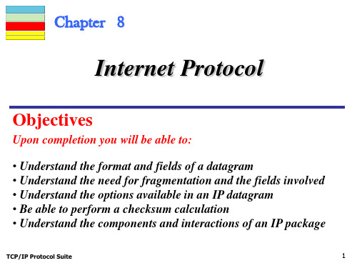
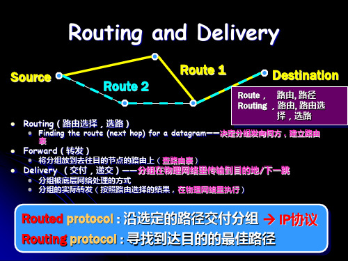


CHAPTER 4: NETWORK LAYER1.Which of the following groups belongs to network layer protocol? _____D____A.IP, TCP and UDPB.ARP, IP, and UDPC.FTP, IMAP and IPD.ICMP, BGP, and RIP2.The 3-PDU is named as ____C_____A.messageB.packetC.datagramD.segment3.In a datagram network, the forwarding decision is based on the value of the____B field in the packet header.A.source addressB.destination addressbelD.None of the choices are4.HOL blocking happens on ____A_____A.input portB.output portC.switching fabricsD.all of above5.If no free buffers in router, the arriving packets will be: AA.droppedB.queuedC.returnedD.marked6.During normal IP packet forwarding at a router, which of the following packetfields are updated? ____C____A.Source IP addressB.Destination IP addressC.ChecksumD.Destination port number7.Which of the following IP address doesn’t belong to the 202.115.32.0/25 network?______D___A.202.115.32.1B.202.115.32.11C.202.115.32.120D.202.115.32.1298.You are given an IP network of 192.168.5.0 and told that you need to separatethis network into sub networks that can support a maximum of 30 hosts per subnet.This will help alleviate congestion on the network. What subnet mask can you use to create the subnets necessary to meet the given criteria? ___C______A.255.255.255.0B.255.255.255.128C.255.255.255.224D.255.255.255.2409.An IP datagram of 1500 bytes (20 byte of IP header plus 1480 bytes of IP payload)arrives at a router and must be forwarded to a link with an MTU of 500 bytes.Thus the router has to fragment the datagram. To the last fragment, the value of offset should be _____D____A.1440B.1000C.186D.18010.IP is a ____C_____ protocol.A.connection-oriented unreliableB.connection-oriented reliableC.connectionless unreliableD.connectionless reliable11.Which ICMP message type is the basis for the Traceroute utility?BA.Echo RequestB.TTL expiredC.Host UnreachableD.Fragment Reassembly Time Exceed12.Routers in the path are not allowed to _________________B__________.A.fragment the packet they receiveB.change source or destination addressC.decapsulate the packetD.All of the choices are correct13.____B_____ allows a site to use a set of private addresses for internalcommunication and a set of global Internet addresses for communication with the rest of the world.A.DHCPB.NATC.ICMPD.None of the choices are correct14.How many bits are there in IPv6 ? ______C___A.32B.64C.128D.25615.In CIDR notation, which of the following networks contains host 192.168.14.2?CA.192.168.10.0/22B.192.168.11.0/21C.192.168.12.0/23D.192.168.13.0/2416.What is the limited broadcast address corresponding to the node with thefollowing IP address: 131.15.46.59?DA.131.15.46.255B.131.15.255.255C.255.255.255.255D.None of the above17.In classful IP addressing, how many network bits does 125.140.128.16 have?AA.8B.16C.24D.3218.What is the broadcast IP address for 193.140.141.128 / 26 ?DA.193.140.141.128B.193.140.141.127C.255.255.255.63D.193.140.141.19119.What’s a network? From IP address perspective they can physically reach eachother without intervening router and the device interfaces with: CA.same IP addressB.same TCP port #C.same network part of IP addressD.same host part of IP address20.The Internet’s network layer has three major components, the first component isthe IP protocol, the second component is the routing protocol, the final component is____.DA.forwardingB.address translationC.checkD.ICMP21.IP addressing assigns an address to 223.10.198.250/29, the network address forthis network is____.A()A.223.10.198.248B.223.10.198.250C.223.10.198.0D.223.10.0.022.There are two 16-bit integers: 1110 0110 0110 0110, 1101 0101 0101 0101. Theirchecksum isA____.A.0100010001000011B.1011101110111100C.1111111111111111D.100000000000000023.The use of hierarchy in routing tables can __A______ the size of the routingtables.A.reduceB.increaseC.neither reduce nor increaseD.None of the choices are correct24.Which of the following protocol doesn’t belong to intra-AS routing protocol?_____B____A.RIPB.BGPC.OSPFD.IRAP25.Which of the following protocol belongs to intra-AS routing protocol?______A___A.RIPB.BGPC.DV (Distance Vector)D.LS (Link State)26.In OSPF network, a ____B_____ belongs to both an area and the backbone.A.internal routerB.area border routerC.boundary routerD.backbone router27._A___ is an inter-domain routing protocol using path vector routing.A.BGPB.RIPC.OSPFD.None of the choices are correct28.RIP uses the services of ___C____.A.TCPB.IPC.UDPD.None of the choices are correct29.The Routing Information Protocol (RIP) is an intra-domain routing based on_______A__ routing.A.distance vectorB.link stateC.path vectorD.all of the above30.Which of the following algorithm has the so called count-to-infinity problem?CA.Flooding algorithmB.Link-state algorithmC.Distance vector algorithmD.None of the above。