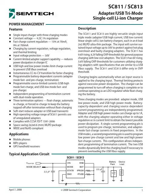
POWER MANAGEMENT Adapter/USB Tri-Mode Single-cell Li-ion ChargerFeaturesSingle input charger with three charging modes Constant voltage — 4.2V, 1% regulationFast-charge current regulation — 15% at 70mA, 9% at 700mACharging by current regulation, voltage regulation, and thermal limitingInput voltage protection — 30VCurrent-limited adapter support capability — reduces power dissipation in charger ICUSB high and low power modes limit charge current to prevent USB Vbus overloadInstantaneous CC-to-CV transition for faster charging Programmable battery-dependent currents (adapter mode fast- and pre-charge, termination)Programmable source-limited currents (USB-high mode fast-charge, and USB-low mode fast- and pre-charge)Independent programming of termination current with dual-mode operation Three termination options — fl oat-charge, automatic re-charge, or forced re-charge to keep the battery topped-off after termination without fl oat-charging Soft-start reduces adapter or USB load transients High operating voltage range of SC811 permits use of unregulated adaptersComplies with CCSA YD/T 1591-2006Space saving 2x2x0.6 (mm) MLPD package WEEE and RoHS compliantApplicationsMobile phones MP3 playersGPS handheld receiversDescriptionThe SC811 and SC813 are highly versatile single input triple mode (adapter/USB high current, USB low current) linear single-cell Li-ion battery chargers, each in an 8 lead 2x2 MLPD ultra-thin package. The input will survive sus-tained input voltage up to 30V to protect against hot plug overshoot and faulty charging adapters. The SC811 has 9.6V rising, 8.2V falling OVP thresholds for general purpose charging with low cost adaptors. The SC813 has 6V rising, 5.6V falling OVP thresholds for customers utilizing charg-ing adapters with specifi cations that are similar to a USB Vbus supply. The SC811 and SC813 differ only in OVP threshold.Charging begins automatically when an input source is applied to the charging input. Thermal limiting protects against excessive power dissipation. The charger can be programmed to turn off when charging is complete or to continue operating as an LDO regulator while fl oat-charg-ing the battery.Three charging modes are provided: adapter mode, USB low power mode, and USB high power mode. Battery-capacity-dependent and charging source-dependent current programming are independently programmed. Adapter and USB high power modes can charge up to 1A, with the charging adapter operating either in voltage regulation or in current limit to obtain the lowest possible power dissipation. A single current programming pin is used to program pre-charge, termination, and adapter-mode fast-charge currents in fixed proportions. In the USB modes, a second programming pin is used to program low power pre-charge current and low and high power fast-charge currents. This confi guration allows indepen-dent programming of termination current. The two USB modes dynamically limit the charging load if necessary to prevent overloading the USB Vbus supply.V ADAPTERSC811 / SC813Typical Application CircuitPin Confi gurationMarking InformationOrdering InformationDevicePackageSC811ULTRT (1)(2)MLPD-UT-8 2×2SC813ULTRT (1)(2)MLPD-UT-8 2×2SC811EVB Evaluation Board SC813EVBEvaluation BoardNotes:(1) Available in tape and reel only. A reel contains 3,000 devices.(2) Lead-free package only. Device is WEEE and RoHS compliant.Exceeding the above specifi cations may result in permanent damage to the device or device malfunction. Operation outside of the parameters specifi ed in the Electrical Characteristics section is not recommended.NOTES:(1) Tested according to JEDEC standard JESD22-A114-B.(2) This is the input voltage at which the charger is guaranteed to begin operation. Maximum operating voltage is the maximum Vsupply asdefined in EIA/JEDEC Standard No. 78, paragraph 2.11.(3) Calculated from package in still air, mounted to 3 x 4.5 (in), 4 layer FR4 PCB with thermal vias under the exposed pad per JESD51 standards.Absolute Maximum RatingsVIN (V) . . . . . . . . . . . . . . . . . . . . . . . . . . . . . . . . . . . . . -0.3 to +30.0BAT, IPRGM, IPUSB (V) . . . . . . . . . . . . . . . . . . . . . . . . .-0.3 to +6.5STATB, ENB, MODE (V) . . . . . . . . . . . . . . . . . . .-0.3 to V BAT + 0.3VIN Input Current (A) . . . . . . . . . . . . . . . . . . . . . . . . . . . . . . . . 1.5Total Power Dissipation (W) . . . . . . . . . . . . . . . . . . . . . . . . . . . 2BAT, IPRGM, IPUSB Short to GND Duration . . . . Continuous ESD Protection Level (1) (kV) . . . . . . . . . . . . . . . . . . . . . . . . . . . . 2Recommended Operating ConditionsOperating Ambient Temperature (°C) . . . . . . . . . -40 to +85SC811:VIN Adapter Mode Operating Voltage (2) (V) . . . 4.60 to 8.20VIN USB Modes Operating Voltage (2) (V) . . . . . . 4.35 to 8.20SC813:VIN Adapter Mode Operating Voltage (2) (V) . . . 4.60 to 5.60VIN USB Modes Operating Voltage (2) (V) . . . . . . 4.35 to 5.60Thermal InformationThermal Resistance, Junction to Ambient (3) (°C/W) . . . . . 68Junction Temperature Range (°C) . . . . . . . . . . . . . . . . . . +150Storage Temperature Range (°C) . . . . . . . . . . . . -65 to +150Peak IR Reflow Temperature (°C) . . . . . . . . . . . . . . . . . . . +260Test Conditions: V VIN = 4.75V to 5.25V; V BAT = 3.7V; Typ values at 25°C; Min and Max at -40°C < T A < 85°C, unless specifi ed.ParameterSymbolConditions MinTypMaxUnitsVIN Adapter Mode Rising Threshold VT ADUVLO-R 4.304.45 4.60V VIN Adapter Mode Falling Threshold (1)VT ADUVLO-F V VIN > V BAT 2.702.853.00V VIN USB Modes Rising Threshold VT USBUVLO-R V VIN > V BAT4.204.35V VIN USB Modes Falling Threshold VT USBUVLO-F V VIN > V BAT3.654.00V VIN USB Modes HysteresisVT USBUVLO-H VT USBUVLOR - VT USBUVLOF 100mVVIN OVP Rising ThresholdVT OVP-RAll modes, SC8119.09.6VAll modes, SC813 5.856.0VIN OVP Falling ThresholdVT OVP-FAll modes, SC8118.28.8VAll modes, SC8135.6 5.75VIN OVP HysteresisVT OVP-HVT OVP-R - VT OVP-F , all modes, SC81150200mVVT OVP-R - VT OVP-F , all modes, SC81350100Electrical CharacteristicsParameterSymbolConditionsMin TypMaxUnitsVIN Charging Disabled Quiescent CurrentIq VIN_DIS V ENB = V BAT23mA VIN Charging Enabled Quiescent CurrentIq VIN_EN V ENB = 0V,excluding I BAT , I IPRGM , and I IPUSB 23mA CV Regulation Voltage V CV I BAT = 50mA, -40°C ≤ T J ≤ 125°C4.16 4.204.24V CV Voltage Load Regulation V CV_LOAD Relative to V CV @ 50mA, 1mA ≤ I BAT ≤ 1A, -40°C ≤ T J ≤ 125°C-2010mV Re-charge Threshold VT ReQ V CV - V BAT60100140mV Pre-charge Threshold (rising)VT PreQ 2.852.90 2.95V Battery Leakage Currentl BAT_V0V BAT = V CV , V VIN = 0V 0.11μA l BAT_DIS V BAT = V CV , V VIN = 5V, V ENB = 2V0.11μA l BAT_MONV BAT = V CV , V VIN = 5V; ENB not connected0.11μA IPRGM Programming Resistor R IPRGM 2.0529.4kΩFast-Charge Current, Adapter Mode I FQ_AD R IPRGM = 2.94kΩ, VT PreQ < V BAT < V CV 643694745mA Pre-Charge Current, Adapter Mode and USB High Power Mode I PreQ_AD R IPRGM = 2.94kΩ, 1.8V < V BAT < VT PreQ105139173mA Termination Current, Any Mode I TERM R IPRGM = 2.94kΩ, V BAT = V CV596980mA IPUSB Programming Resistor R IPUSB 2.0529.4kΩFast-Charge Current, USB High Power ModeI FQ_USB R IPUSB = 4.42kΩ, 1.8V < V BAT < VT PreQ 427462497mA Pre-Charge Current and Fast-Charge Current, USB Low Power Mode I PreQ_USB R IPUSB = 4.42kΩ, 1.8V < V BAT < V CV 6992116mA Dropout VoltageV DO I BAT = 700mA, 0°C ≤ T J ≤ 125°C 0.400.60V IPRGM Fast-charge Regulated Voltage V IPRGM_FQ V VIN = 5.0V, VT PreQ < V BAT < V CV2.04V IPRGM Pre-charge Regulated Voltage V IPRGM_PQ 1.8V < V BAT < VT PreQ 0.408V IPRGM Termination Threshold Voltage VT IPRGM_TERM V BAT = V CV(either input selected)0.204V IPUSB Fast-charge Regulated Voltage V IPUSB_FQ V VIN = 0V, VT PreQ < V BAT < V CV2.04V IPUSB Pre-charge or USB Low Power Mode Regulated VoltageV IPUSB_PQ V VIN = 0V, V BAT < VT PreQ0.408VVIN USB Modes Under-Voltage Load Regulation Limiting VoltageV UVLR5mA ≤ VIN supply current limit ≤500mA, V MODE = 2V, R IPUSB = 3.65kΩ (559mA)4.45 4.58 4.70VElectrical Characteristics (continued)Electrical Characteristics (continued)ParameterSymbolConditions Min TypMax UnitsThermal Limiting Threshold Temperature T TL 130°C Thermal Limiting Ratei T 50mA/ °C ENB or MODE Input High Voltage ThresholdV IH 1.6VENB or MODE Input Mid Voltage Range V IM 0.71.3V ENB or MODE Input Low Voltage ThresholdV IL 0.3V ENB Input High-range Threshold Input CurrentI ENB_IH_TH ENB current required to pull ENB from floating midrange into high range 2350μAENB Input High-range Sustain Input CurrentI ENB_IH_SUS Current required to hold ENB in high range, Min V IH ≤ V ENB ≤ V BAT ,Min V IH ≤ V BAT ≤ 4.2V0.31μA MODE Input High-range Input Current I MODE_IH V MODE = Min V IH2375μA ENB or MODE Input Mid-range Load LimitI IM Input will float to mid range when thisload limit is observed.-55μA ENB or MODE Input Low-range Input CurrentI IL 0V ≤ (V ENB or V MODE ) ≤ Max V IL -2512μA MODE Input Monitor State Input CurrentI MODE_MON V MODE = V BAT = 4.2V,V ENB = 1V and Charging Terminated1μA ENB or MODE Input Leakage I ILEAK V VIN = 0V or V VIN = 5V, V ENB and V MODE = V BAT = 4.2V1μA STATB Output Low Voltage V STAT_LO I STAT_SINK = 2mA 0.5V STATB Output High CurrentI STAT_HIV STAT = 5V1μANotes:(1) Sustained operation to VT ADUVLO-F ≤ V VIN is guaranteed only if a current limited charging source applied to VIN is pulled below VT ADUVLO-R by thecharging load; forced VIN voltage below VT ADUVLO-R may in some cases result in regulation errors or other unexpected behavior.Typical CharacteristicsCV Line RegulationCV Load RegulationCV Temperature RegulationCC AD or USB High FQ Line RegulationCC AD or USB High FQ V BAT RegulationCC AD or USB High FQ Temperature RegulationTypical CharacteristicsCC USB Low Power FQ Line RegulationCC USB Low Power FQ VRegulationCC USB Low Power FQ Temperature RegulationCC PQ Line RegulationCC PQ Temperature RegulationTypical CharacteristicsI FQ_AD vs. R IPRGM , or I FQ_USB High Power vs. R IPUSBIor I vs. R , or I Low Power vs. R Charging Cycle Battery Voltage and CurrentPre-Charging Battery Voltage and CurrentCC-to-CV Battery Voltage and CurrentRe-Charge Cycle Battery Voltage and CurrentTypical CharacteristicsMode Reselection — USB Low to USB HighMode Reselection — USB High to USB LowMode Reselection — AD to USB HighMode Reselection — USB High to ADMode Reselection — AD to USB LowMode Reselection — USB Low to AD100μs/divI BAT (100mA/div))V MODE =0V—V MODE (2V/div)I BAT =0mA—V VIN =5V, V BAT=3.7V100μs/div I BAT (100mA/div)V MODE =0V—V MODE (2V/div)I BAT =0mA—V VIN =5V, V BAT=3.7V100μs/divI BAT (100mA/div)V MODE (2V/div)V VIN =5V, V BAT=3.7V100μs/divI BAT (100mA/div)V MODE (2V/div)V VIN =5V, V BAT=3.7V100μs/divI BAT (100mA/div)V MODE =0V—V MODE (2V/div)I BAT =0mA—V VIN =5V, V BAT=3.7V100μs/divI BAT (100mA/div)V MODE =0V—V MODE (2V/div)I BAT =0mA—V VIN =5V, V BAT =3.7VV MODE =0V—I BAT =0mA—V MODE =0V—I BAT =0mA—Pin DescriptionsPin #Pin Name Pin Function1VIN Supply pin — connect to charging adapter (wall adapter or USB). This pin is protected against damage due to high voltage up to 30V.2MODE Charging mode selection (tri-level logical) input — Logical high selects USB high power mode, fl oating selects USB low power mode, ground selects adapter mode.3STATB Status output pin — This open-drain pin is asserted (pulled low) when a valid charging supply is connected to the VIN pin, and a charging cycle begins. It is released when the termination current is reached, indicating that charging is complete. STATB is not asserted for re-charge cycles.4GND Ground5IPUSB Fast-charge and pre-charge current programming pin for a USB mode charging source — USB high power mode (100%) and low power mode (20%) fast-charge current are programmed by connecting a resistor from this pin to ground. USB low power mode pre-charge current is equal to the low power mode fast-charge current (20% of USB high power mode fast-charge current).6 IPRGM Adapter mode fast-charge, adapter and USB high power modes pre-charge, and all modes termination current programming pin — Connect a resistor from this pin to ground. Pre-charge current is 20% of IPRGM-programmed adapter mode fast-charge current when in adapter mode or USB high power mode. The charging termination current threshold (for adapter or either USB mode selection) is 10% of the IPRGM programmed fast-charge current.7BAT Charger output — connect to battery positive terminal.8ENB Combined device enable/disable — Logic high disables the device. Tie to GND to enable charging with indefi nite fl oat-charging. Float this pin to enable charging without fl oat-charge upon termination. Note that this pin must be grounded if the SC811/3 is to be operated without a battery connected to BAT.T Thermal Pad Pad is for heatsinking purposes —not connected internally. Connect exposed pad to ground plane using multiple vias.Block DiagramCharger OperationThe SC811/3 is a single input tri-mode stand-alone Li-ion battery charger. (The SC811 diff ers from the SC813 only in the input voltage Over Voltage Protection threshold.) It provides selections of adapter mode and USB high and low power mode charging. The device is independently programmed for battery capacity dependent currents (adapter fast-charge current and termination current) using the IPRGM pin. Charging currents from the USB Vbus supply, which has a maximum load specifi cation, are programmed using the IPUSB pin when either of the USB modes is selected.When an input supply is fi rst detected, a charge cycle is initiated and the STATB open-drain output goes low. If the battery voltage is less than the pre-charge threshold voltage, the pre-charge current is supplied. Pre-charge current is 20% of the IPRGM (adapter or USB high power modes) or IPUSB (USB low power mode) programmed fast-charge current.When the battery voltage exceeds the pre-charge thresh-old, typically within seconds for a standard battery with a starting cell voltage greater than 2V, the fast-charge Constant Current (CC) mode begins. The charge current soft-starts in three steps (20%, 60%, and 100% of pro-grammed fast-charge current) to reduce adapter load transients. CC current is programmed by the IPRGM resis-tance to ground when adapter mode is selected and by the IPUSB resistance to ground when either USB mode is selected. In USB low power mode, the CC current is held at 20% of the IPUSB programmed fast-charge current.The charger begins Constant Voltage (CV) regulation when the battery voltage rises to the fully-charged single-cell Li-ion regulation voltage (V CV ), nominally 4.2V. In CV regulation, the output voltage is regulated, and as the battery charges, the charge current gradually decreases. The STATB output goes high when I BAT drops below the termination threshold current, which is 10% of the IPRGM pin programmed fast-charge current regardless of the mode selected. This is known as charge termination.Optional Float-charging or MonitoringDepending on the state of the ENB input, upon termina-tion the SC811/3 either operates indefi nitely as a voltage regulator (known as float-charging) or it turns off itsoutput. If the output is turned off upon termination, the device enters the monitor state. In this state, the output remains off until the BAT pin voltage decreases by the re-charge threshold (VT ReQ ). A re-charge cycle then begins automatically and the process repeats. A forced re-charge cycle can also be periodically commanded by the processor to keep the battery topped-off without fl oat-charging. See the Monitor State section for details. Re-charge cycles are not indicated by the STATB pin.Charging Input Pin Mode DependenciesThe UVLO rising and falling thresholds are adjusted with the charging mode selected. In adapter mode, if the charging current loads the adapter beyond its current limit, the input voltage will be pulled down to just above the battery voltage. The adapter mode UVLO falling threshold is set close to the battery voltage pre-charge threshold to permit low-dissipation charging from a current limited adapter.The USB modes provide a higher UVLO falling threshold applicable to the USB specifi cation. The USB modes also provide Under-Voltage Load Regulation (UVLR), in which the charging current is reduced if needed to prevent overloading of the USB Vbus supply. UVLR can serve as a low-cost alternative to directly programming the USB low power charge current. This can be beneficial for charging small batteries, for which the USB high power fast-charge current must be programmed to less than 500mA. The fi xed 20% USB low power mode fast-charge current would be less than 100mA and, therefore, is unsuitable for minimum charge-time applications. UVLR can also be used where there is no signal available to indicate whether USB low or high power mode should be selected.All modes use the same input Over-Voltage Protection (OVP) threshold as defi ned in the Electrical Characteristics section for the device being used.Constant Current Mode Fast-charge Current ProgrammingConstant Current (CC) regulation is active when the battery voltage is above VT PreQ and less than V CV . When adapter mode is selected, the programmed CC regula-tion fast-charge (FQ) current is inversely proportional toApplications InformationApplications Information (continued)the resistance between IPRGM and GND according to the equation59,,35*07\SB ,35*0$'B )4When either of the USB modes is selected, the pro-grammed CC regulation fast-charge current is inversely proportional to the resistance between IPUSB and GND according to the equation59,,386%7\S B ,386%86%B )4The fast-charge current can be programmed for a minimum of 70mA and a maximum of 995mA for either adapter or USB high power mode. This range for both modes permits the use of USB high power mode for general purpose adapter charging, allowing fully inde-pendent programming of termination current. (See the application sections, Independent Programming of Termination Current, and USB-only Charging of Very Large Batteries.)Current regulation accuracy is dominated by gain error at high current settings, and off set error at low current set-tings. The range of expected fast-charge output current versus programming resistance R IPRGM or R IPUSB (for adapter or USB high power mode, respectively) is shown in Figures1a and 1b. Each figure shows the nominal fast-charge current versus nominal R IPRGM or R IPUSB resistance as the center plot, and two theoretical limit plots indicating maximum and minimum current versus nominal pro-gramming resistance. These plots are derived from models of the expected worst-case contribution of error sources depending on programmed current. The current range includes the uncertainty due to 1% tolerance resis-tors. The dots on each plot indicate the currents obtained with standard value 1% tolerance resistors. Figures 1a and 1b show low and high resistance ranges, respectively. The USB low power mode fast-charge current accuracy is exactly like that of pre-charge in high power mode. USB low power mode current regulation accuracy is addressed in the next section.Pre-charge and USB Low Power Mode Fast-charge Current RegulationPre-charging is automatically selected when the battery voltage is below the pre-charge threshold voltage (VT PreQ ), typically 2.8V. Pre-charge current conditions the battery for fast charging. The pre-charge current value is fi xed at 20% nominally of the fast-charge current. It is pro-grammed by the resistance between IPRGM and GND for adapter mode and USB high power mode, and by the resistance between IPUSB and GND for USB low power mode. Note that USB low power mode pre-charge current is equal to USB low power mode fast-charge current.Figure 1a — Fast-charge Current Tolerance versus Programming Resistance, Low Resistance RangeFigure 1b — Fast-charge Current Tolerance versus Programming Resistance, High Resistance RangePre-charge current regulation accuracy is dominated by offset error. The range of expected pre-charge output current versus programming resistance R IPRGM or R IPUSB is shown in Figures 2a and 2b. Each figure shows the nominal pre-charge current versus nominal R IPRGM or R IPUSB resistance as the center plot and two theoretical limit plots indicating maximum and minimum current versus nominal programming resistance. These plots are derived from models of the expected worst-case contribution of error sources depending on programmed current. The current range includes the uncertainty due to 1% toler-ance resistors. The dots on each plot indicate the currents obtained with standard value 1% tolerance resistors. Figures 2a and 2b show low and high resistance ranges, respectively.TerminationWhen the battery voltage reaches V CV , the SC811/3 transi-tions from constant current regulation to constant voltageregulation. While V BAT is regulated to V CV , the current into the battery decreases as the battery becomes fully charged. When the output current drops below the termi-nation threshold current, charging terminates. Upon termination, the STATB pin open drain output turns off and the charger either enters monitor state or float-charges the battery, depending on the logical state of the ENB input pin.Applications Information (continued)The termination threshold current is fi xed at 10% of the adapter mode fast-charge current, as programmed by the resistance between IPRGM and GND, for all charging modes. If only the USB modes will be used, the termina-tion threshold current can be programmed independently of the fast-charge current. (See the application sections, Independent Programming of Termination Current, and USB-only Charging of Very Large Batteries.)Charger output current is the sum of the battery charge current and the system load current. Battery charge current changes gradually, and establishes a slowly diminishing lower bound on the output current while charging in CV mode. The load current into a typical digital system is highly transient in nature. Charge cycle termination is detected when the sum of the battery charging current and the greatest load current occurring within the immediate 300μs to 550μs past interval is less than the programmed termination current. This timing behavior permits charge cycle termination to occur during a brief low-load-current interval, and does not require that the longer interval average load current be small.Termination threshold current accuracy is dominated by off set error. The range of expected termination current versus programming resistance R IPRGM (for any charging mode) is shown in Figures 3a and 3b. Each fi gure showsFigure 2a — Pre-charge Current and USB Low Power Mode Fast-charge Current Tolerance vs. ProgrammingResistance, Low Resistance RangeFigure 2b — Pre-charge Current and USB Low Power Mode Fast-charge Current Tolerance vs. ProgrammingResistance, High Resistance Rangethe nominal termination current versus nominal R IPRGM resistance as the center plot and two theoretical limit plots indicating maximum and minimum current vs. nominal programming resistance. These plots are derived from models of the expected worst-case contribution of error sources depending on programmed current. The current range includes the uncertainty due to a 1% tolerance resistor. The dots on each plot indicate the currents obtained with standard value 1% tolerance resistors. Figures 3a and 3b show low and high resistance ranges, respectively.Tri-level Logical Input PinsThe MODE and ENB pins are tri-level logical inputs. They are designed to interface to a processor GPIO port that is powered from a peripheral supply voltage as low as 1.8V or as high as a fully charged battery. While a connected GPIO port is confi gured as an output, the processor writes 0 to select ENB or MODE low-range, and 1 to select high-range. The GPIO port is confi gured as an input to select mid-range.These pins can also be permanently grounded to select low-range or left unconnected to select mid-range for fi xed mode operation. The MODE pin can also be perma-nently connected to a logical high voltage source, such as BAT or a regulated peripheral supply voltage.The equivalent circuit looking into these pins is a variable resistance, minimum 15kΩ, to an approximately 1V source.The input will fl oat to mid range whenever the external driver sinks or sources less than 5μA, a common worst-case characteristic of a high impedance GPIO, or a weak pull-up or pull-down GPIO, confi gured as an input. The driving GPIO must be able to sink or source at least 75μA to ensure a low or high state, respectively, although the drive current is typically far less. (See the Electrical Characteristics table.)Mode InputThe MODE pin is a tri-level logical input. When driven high (V MODE > Min V IH ), the SC811/3 will operate in USB High Power mode. If the MODE input voltage is within its speci-fi ed mid range (Min V IM < V ENB < Max V IM ), either by fl oating (by reconfi guring its GPIO as an input) or by being exter-nally forced, the SC811/3 will operate in USB Low Power mode. When driven low (V MODE < Max V IL ), the SC811/3 will operate in adapter mode.When there is no charging source present, when the charger is disabled, or when operating in the monitor state (described in a later section), the MODE pin enters a high impedance state, suspending the tri-level functional-ity. Upon re-charge or re-enabling the charger, the MODE pin tri-level interface is reactivated.Typically a processor GPIO port direction defaults to input upon processor reset, or is high impedance when un-powered. This is the ideal initial condition for driving the MODE pin, since this will select USB Low Power mode,Programming Resistance, Low Resistance RangeProgramming Resistance, High Resistance RangeApplications Information (continued)which is the safest default mode with the lowest fast-charge current.Enable InputThe ENB pin is a tri-level logical input that allows selection of the following behaviors:charging enabled with fl oat-charging after ter-mination (ENB = low range)charging enabled with fl oat-charging disabled and battery monitoring at termination (ENB = mid range)charging disabled (ENB = high range).If the ENB input voltage is permitted to fl oat to mid-range, the charger is enabled but it will turn off its output follow-ing charge termination and will enter the monitor state. This state is explained in the next section. Mid-range can be selected either by floating the input (sourcing or sinking less than 5μA) or by being externally forced such that V ENB falls within the midrange limits specifi ed in the Electrical Characteristics table.When driven low (V ENB < Max V IL ), the charger is enabled and will continue to float-charge the battery following termination. If the charger is already in monitor state fol-lowing a previous termination, it will exit the monitor state and begin fl oat-charging.When ENB is driven high (V ENB > Min V IH ), the charger is disabled and the ENB input pin enters a high impedance state, suspending tri-level functionality. The specified high level input current I IH is required only until a high level is recognized by the SC811/3 internal logic. The tri-level float circuitry is then disabled and the ENB input becomes high impedance. Once forced high, the ENB pin will not fl oat to mid range. To restore tri-level operation, the ENB pin must fi rst be pulled down to mid or low range (at least to V ENB < Max V IM ), then, if desired, released (by reconfi guring the GPIO as an input) to select mid-range. If the ENB GPIO has a weak pull-down when confi gured as an input, then it is unnecessary to drive ENB low to restore tri-level operation; simply confi gure the GPIO as an input. When the ENB selection changes from high-range to mid- or low-range, a new charge cycle begins and STATB goes low.•••Note that if a GPIO with a weak pull-up input confi gura-tion is used, its pull-up current will fl ow from the GPIO into the ENB pin while it is fl oating to mid-range. Since the GPIO is driving a 1V equivalent voltage source through a resistance (looking into ENB), this current is small — pos-sibly less than 1μA. Nevertheless, this current is drawn from the GPIO peripheral power supply and, therefore, from the battery after termination. (See the next section, Monitor State.) For this reason, it is preferable that the GPIO chosen to operate the ENB pin should provide a true high impedance (CMOS) configuration or a weak pull-down when confi gured as an input. When pulled below the fl oat voltage, the ENB pin output current is sourced from VIN, not from the battery.Monitor StateIf the ENB pin is fl oating, the charger output and STATB pin will turn off and the device will enter the monitor state when a charge cycle is complete. If the battery voltage falls below the re-charge threshold (V CV - V ReQ ) while in the monitor state, the charger will automatically initiate a re-charge cycle. The battery leakage current during monitor state is no more than 1μA over temperature and typically less than 0.1μA at room temperature.While in the monitor state, the ENB tri-level input pin remains fully active, and although in midrange, is sensitive to both high and low levels. The SC811/3 can be forced from the monitor state (no fl oat-charging) directly to fl oat-charging operation by driving ENB low. This operation will turn on the charger output, but will not assert the STATB output. If the ENB pin is again allowed to float to mid-range, the charger will remain on only until the output current becomes less than the termination current, and charging terminates. The SC811/3 turns off its charging output and returns to the monitor state within a millisec-ond. This forced re-charge behavior is useful for periodically testing the battery state-of-charge and topping-off the battery, without float-charging and without requiring the battery to discharge to the auto-matic re-charge voltage. ENB should be held low for at least 1ms to ensure a successful forced re-charge.Forced re-charge can be requested at any time during the charge cycle, or even with no charging source present, with no detrimental effect on charger operation. This allows the host processor to schedule a forced re-charge。