
ds-07
- 格式:ppt
- 大小:507.00 KB
- 文档页数:121

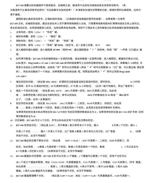
DS7400报警主机的编程并不是很复杂。
在编程之前,敬请用户必须先详细地阅读安装使用说明书,(再次敬请用户认真阅读使用说明书!可达到事半功倍的效果!)并清楚的知道你所需要的功能,根据所需列出编程表,这样方便于编程。
编程前请认真阅读说明书,正确的接好连线。
(正确接好连线是编好程序的前提)。
如果是第一次使用DS7400主机,在编程完成前,建议安装技术人员不要将探测器接入主机,只需要将线尾电阻和扩展模块接在主机上就可以,将主机调试好后,在将探测器接入防区,这样如果系统有故障,有利于工程技术人员判断是主机系统故障还是探测器故障。
1.正常布防:密码(1234) + “布防”键。
2.撤防和消警:密码(1234 )+ “撤防”键。
3.强制布防:密码(1234 )+ “布防”键+ “旁路”键4.防区旁路:密码(1234) + “旁路”键+XXX (防区号,且一定是三位数,女口008)5.进入编程和退出编程:进入编程是9876#0 (密码+#0),退出编程是按“ * ”四秒钟,听到“嘀” 一声表示己退出编程。
6.如何填写数据:DS7400主机的编程地址一定是四位数,地址的数据一定是两位数。
进入编程后,键盘的灯都会闪动,LCD显示:Prog Mode 4. 05 Adr二DS7400 Adr=后而的就是要写上去的四位数的地址。
输入地址后,接着输入21#则会交替显示该地址上的两位数据;或者按“井”则可以出现数据1;再按“ #”则可出现数据2o (岀厂值,可以通过编程改变的),然后自动跳到下一个地址。
如果需要对某些地址编程,则需连续按两次“ *”则可以回到Prog Mode4.05 Adr=?7.确定防区的功能:(地址是0001 -0030),所谓防区功能就是该防区是延时防区、即时防区、24小时防区等等。
其中01代表延时防区;03代表即时防区;07代表24小时防区。
(此项一般不用编写,用出厂值即可)8.确定一个防区的功能:(地址是0031 -0278) , 0031代表第一防区,0032代表第二防区,如此类推....如果想把第八防区设定为即时防区,即可以把地址0038中的数据改为03,再按“ 确认就可以了。

◆研究与开发◆[摘要]分析了钾长石、磷矿、磷酸不同组合反应体系的钾、磷溶出率,并用XRD和FTIR对反应物和产物进行了物相分析。
实验结果表明:磷酸不能分解钾长石,但加入磷矿以后,钾长石中钾可以被大量提出;反应分二步,首先是磷酸分解磷矿生成可溶于水的Ca(H2PO4)2和HF,然后HF能分解钾长石,但钾长石中钾的提取主要是Ca(H2PO4)2电离的Ca2+与钾长石中K+发生离子交换反应的结果。
实验结果还表明,体系中的氟也会以K2SiF6的形式固定钾而降低钾的溶出率。
[关键词]钾长石;磷矿;磷酸;提钾;反应机理[中图分类号]TQ443.5[文献标识码]A[文章编号]1007-6220(2007)05-0019-04ResearchonthereactionmechanismofpotashfeldsparandphosphaterockinthephosphoricacidHANXiao-zhao1,2,YANYong1,HUBo1,HUXian-guo2(1.SchoolofChemicalEngineering,HefeiUniversityofTechnology,Hefei,Anhui230009,China;2.SchoolofMachineandAutomobileEngineering,HefeiUniversityofTechnology,Hefei,Anhui230009,China)Abstract:Thepotassiumandphosphorusextractionratesarestudiedforthereactivesystemconsistingofnaturalpotashfeldspar,phosphaterockandphosphoricacid,withtheanalysisonreactantsandresultantsbyXRDandFTIR.Theresultsshowthatthepotassiumextractionfromnaturalpotashfeldsparwillbegreatlyincreasedinthesystembothphosphaterockandphosphoricacid,thoughitcan\tbedissolvedbysinglephosphoricacid.Thereare2stepsforthereactiveprocess:firstlythephosphaterockisdissolvedbyphosphoricacidtoformwatersolubleresultantsCa(H2PO4)andHF,thenpotashfeldsparisdecomposedbyHF.ThepotassiumextractionfromnaturalpotashfeldsparresultsfromtheexchangereactionbetweentheCa2+fromCa(H2PO4)dissociationandK+inpotashfeldspar,howeverthepotassiumextractionishinderedforthefixationofK2SiF6onpotassiumion.Keywords:potashfeldspar;phosphaterock;phosphoricacid;potassiumextraction;reactionmechanism钾长石与磷矿磷酸反应机理研究韩效钊1,2,阎勇1,胡波1,胡献国2(1.合肥工业大学化学工程学院,安徽合肥230009;2.合肥工业大学机械与汽车工程学院,安徽合肥230009)[收稿日期]2007-04-07[作者简介]韩效钊(1964-),男,安徽怀宁人,副教授,在职博士生,主要从事非金属矿综合利用及农用肥料精细化研究。
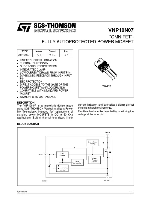
VNP10N07”OMNIFET”:FULLY AUTOPROTECTED POWER MOSFETApril 1996123TO-220BLOCK DIAGRAMTYPE V clamp R DS(on)I l im VNP10N0770V0.1Ω10As LINEAR CURRENT LIMITATION s THERMAL SHUT DOWNs SHORT CIRCUIT PROTECTION s INTEGRATED CLAMPs LOW CURRENT DRAWN FROM INPUT PIN sDIAGNOSTIC FEEDBACK THROUGH INPUT PINs ESD PROTECTIONsDIRECT ACCESS TO THE GATE OF THE POWER MOSFET (ANALOG DRIVING)sCOMPATIBLE WITH STANDARD POWER MOSFETsSTANDARD TO-220PACKAGEDESCRIPTIONThe VNP10N07is a monolithic device made using SGS-THOMSON Vertical Intelligent Power M0Technology,intended for replacement of standard power MOSFETS in DC to 50KHz applications.Built-in thermal shut-down,linear current limitation and overvoltage clamp protect the chip in harsh enviroments.Fault feedback can be detected by monitoring the voltage at the input pin.1/11ABSOLUTE MAXIMUM RATINGSymbol Parameter Value Unit V DS Drain-source Voltage(V in=0)Internally Clamped V V in Input Voltage18VI D Drain Current Internally Limited AI R Reverse DC Output Current-14AV esd Electrostatic Discharge(C=100pF,R=1.5KΩ)2000V P to t Total Dissipation at T c=25o C50W T j Operating Junction Temperature Internally Limited o C T c Case Operating Temperature Internally Limited o C T st g Storage Temperature-55to150o CTHERMAL DATAR t hj-ca se R t hj-amb Thermal Resistance Junction-case MaxThermal Resistance Junction-ambient Max2.562.5o C/Wo C/WELECTRICAL CHARACTERISTICS(T case=25o C unless otherwise specified)OFFSymbol Parameter Test Conditions Min.Typ.Max.Unit V CLAMP Drain-source ClampVoltageI D=200mA V in=0607080VV CLTH Drain-source ClampThreshold VoltageI D=2mA V in=055VV I NCL Input-Source ReverseClamp VoltageI in=-1mA-1-0.3VI DSS Zero Input VoltageDrain Current(V in=0)V DS=13V V in=0V DS=25V V in=050200µAµAI I SS Supply Current fromInput PinV DS=0V V in=10V250500µA ON(∗)Symbol Parameter Test Conditions Min.Typ.Max.Unit V IN(th)Input ThresholdVoltageV DS=V in I D+Ii n=1mA0.83VR DS(on)Static Drain-source OnResistance V i n=10V I D=5AV i n=5V I D=5A0.10.14ΩΩDYNAMICSymbol Parameter Test Conditions Min.Typ.Max.Unitg fs(∗)ForwardTransconductanceV DS=13V I D=5A68SC oss Output Capacitance V DS=13V f=1MHz V in=0350500pF VNP10N072/11ELECTRICAL CHARACTERISTICS(continued)SWITCHING(∗∗)Symbol Parameter Test Conditions Min.Typ.Max.Unitt d(on) t r t d(of f) t f Turn-on Delay TimeRise TimeTurn-off Delay TimeFall TimeV DD=15V I d=5AV gen=10V R gen=10Ω(see figure3)5080230100100160400180nsnsnsnst d(on) t r t d(of f) t f Turn-on Delay TimeRise TimeTurn-off Delay TimeFall TimeV DD=15V I d=5AV gen=10V R gen=1000Ω(see figure3)6000.93.81.7900262.5nsµsµsµs(di/dt)on Turn-on Current Slope V DD=15V I D=5AV i n=10V R gen=10Ω60A/µs Q i Total Input Charge V DD=12V I D=5A V in=10V30nC SOURCE DRAIN DIODESymbol Parameter Test Conditions Min.Typ.Max.Unit V SD(∗)Forward On Voltage I SD=5A V in=0 1.6Vt r r(∗∗) Q r r(∗∗) I RRM(∗∗)Reverse RecoveryTimeReverse RecoveryChargeReverse RecoveryCurrentI SD=5A di/dt=100A/µsV DD=30V T j=25o C(see test circuit,figure5)1250.34.8nsµCAPROTECTIONSymbol Parameter Test Conditions Min.Typ.Max.UnitI lim Drain Current Limit V i n=10V V DS=13VV i n=5V V DS=13V 7710101414AAt dl im(∗∗)Step ResponseCurrent Limit V i n=10VV i n=5V20503080µsµsT jsh(∗∗)OvertemperatureShutdown150o C T j rs(∗∗)Overtemperature Reset135o CI gf(∗∗)Fault Sink Current V i n=10V V DS=13VV i n=5V V DS=13V 5020mAmAE as(∗∗)Single PulseAvalanche Energy starting T j=25o C V DD=20VV i n=10V R gen=1KΩL=10mH0.4J(∗)Pulsed:Pulse duration=300µs,duty cycle1.5%(∗∗)Parameters guarant eed by design/c haracterizationVNP10N073/11During normal operation,the Input pin is electrically connected to the gate of the internal power MOSFET.The device then behaves like a standard power MOSFET and can be used as a switch from DC to50KHz.The only difference from the user’s standpoint is that a small DC current(I iss)flows into the Input pin in order to supply the internal circuitry.The device integrates:-OVERVOLTAGE CLAMP PROTECTION: internally set at70V,along with the rugged avalanche characteristics of the Power MOSFET stage give this device unrivalled ruggedness and energy handling capability. This feature is mainly important when driving inductive loads.-LINEAR CURRENT LIMITER CIRCUIT:limits the drain current Id to Ilim whatever the Input pin voltage.When the current limiter is active, the device operates in the linear region,so power dissipation may exceed the capability of the heatsink.Both case and junction temperatures increase,and if this phase lasts long enough,junction temperature may reach the overtemperature threshold T jsh.-OVERTEMPERATURE AND SHORT CIRCUIT PROTECTION:these are based on sensing the chip temperature and are not dependent on the input voltage.The location of the sensing element on the chip in the power stage area ensures fast,accurate detection of the junction temperature.Overtemperature cutout occurs at minimum150o C.The device is automatically restarted when the chip temperature falls below135o C.-STATUS FEEDBACK:In the case of an overtemperature fault condition,a Status Feedback is provided through the Input pin. The internal protection circuit disconnects the input from the gate and connects it instead to ground via an equivalent resistance of100Ω. The failure can be detected by monitoring the voltage at the Input pin,which will be close to ground potential.Additional features of this device are ESD protection according to the Human Body model and the ability to be driven from a TTL Logic circuit(with a small increase in R DS(on)).PROTECTION FEATURES VNP10N074/11Thermal ImpedanceOutput CharacteristicsStatic Drain-Source On Resistance vs Input Voltage Derating CurveTransconductanceStatic Drain-Source On ResistanceVNP10N075/11Static Drain-Source On Resistance Capacitance VariationsNormalized On Resistance vs Temperature Input Charge vs Input Voltage Normalized Input Threshold Voltage vs TemperatureNormalized On Resistance vs TemperatureVNP10N07 6/11Turn-on Current SlopeTurn-off Drain-Source Voltage Slope Switching Time Resistive Load Turn-on Current SlopeTurn-off Drain-Source Voltage SlopeSwitching Time Resistive LoadVNP10N077/11Switching Time Resistive Load Step Response Current Limit Current Limit vs Junction Temperature Source Drain Diode Forward CharacteristicsVNP10N07 8/11Fig.2:Unclamped Inductive WaveformsFig.3:Switching Times Test Circuits For Resistive Load Fig.4:Input Charge Test CircuitFig.1:Unclamped Inductive Load Test CircuitsFig.5:Test Circuit For Inductive Load Switching And Diode Recovery Times Fig.6:WaveformsVNP10N079/11DIM.mminch MIN.TYP.MAX.MIN.TYP.MAX.A 4.40 4.600.1730.181C 1.23 1.320.0480.051D 2.402.720.0940.107D1 1.270.050E 0.490.700.0190.027F 0.610.880.0240.034F1 1.14 1.700.0440.067F2 1.14 1.700.0440.067G 4.95 5.150.1940.203G1 2.4 2.70.0940.106H210.010.400.3930.409L216.40.645L413.014.00.5110.551L5 2.65 2.950.1040.116L615.2515.750.6000.620L7 6.2 6.60.2440.260L9 3.5 3.930.1370.154DIA.3.75 3.850.1470.151L6ACDED 1FGL7L2Dia.F 1L5L4H 2L9F 2G 1TO-220MECHANICAL DATAP011CVNP10N0710/11元器件交易网VNP10N07 Information furnished is believed to be accurate and reliable.However,SGS-THOMSON Microelectronics assumes no responsabilit y for theconsequences of use of such information nor for any infringemen t of patents or other rights of third parties which may results from its use.Nolicense is granted by implication or otherwise under any patent or patent rights of SGS-THOMSON Microelectr onics.Specifications mention edin this publication are subject to change without notice.This publication supersede s and replaces all information previously supplied.SGS-THOMSON Microelectr onics products are not auth orized for use as critical compon ents in life support devices or systems without expre sswritten approval of SGS-THOMSON Microelectonics.©1996SGS-THOMSON Microelectronics-Printed in Italy-All Rights Reserve dSGS-THOMSON Microelectronics GROUP OF COMPANIESAustralia-Brazil-Canada-China-France-Germany-Hong Kong-Italy-Japan-Korea-Malaysia-Malta-Morocco-The Netherlands-Singapore-Spain-Sweden-Switzerland-Taiwan-Thailand-United Kingdom-U.S.A.11/11。