
A-4E战斗机模型制作
- 格式:ppt
- 大小:7.66 MB
- 文档页数:48


BUILDING INSTRUCTIONSFoamy Factory Models Mini Series Class: Indoor/Light OutdoorWingspan: 33"Flying Weight: 5.5-8oz.Servos: 3 x Pico's/hs55's/BMS 306, etc.Battery: 2s1p 360-720mah Lipoly (depends on motor choice)Brushless Motor Options: Little Screamers, Cemech Python 60, Axi 2208/34, Axi 2204/54 Included in Kit -3mm Depron airframe parts(2) .121”x .034” x 36”(3mm x .8mm) flat carbon fiber strips.(2) 8.75”x.080” (2mm) carbon landing gear legs(2) 11”x.060” (1.5mm) carbon pushrods(2) 4”x.060” (1.5mm) carbon pushrods(10) .039” x 2” music wire(1) Silicone rubber gear leg bushing(1) 2” length plastic tubing (1) Cotton thread(1) Kevlar thread for truss bracing system (1) 1/8” lite-ply firewall(3) 3mm Depron firewall spacers(4) 2/56 cap head screws(2) 1.5” wheels(4) DuBro micro control horns(4) Dubro EZ Links(3-4) Decal sheetsNot Included in Kit -Servos: (3) 6-9 gram servos (HS-55, HS-50, BMS 306, etc.)Motor: CD Rom Motor, Axi 2208/34, Axi 2204/54, or equivalent Battery: 2-3 cell lipoy (depends on motor choice) 340-830maSpeed controller: Appropriate for motor choice (CC Phoenix 10)Prop: depends on motor choice, GWS 8x4.3SF is a good starting point. Receiver: Micro receiverGlue: Medium and Thin foam friendly Ca or UHU CreativeSHARP X-Acto knife (#11 blade works best) or single edge razor blades Cellophane Tape: Clear glossy type (not the disappearing dull finish) 36” metal ruler or straight edge NOTE: All Foamy Factory kits are precision CNC router cut. Some cut flashing/fuzz may be present on some of the foam/wood parts. This is due to the rotary cut action of the router and the direction of the cut and is not a defect. If any flashing/fuzz is present, lightly sand the edges with 1200 grit sandpaper.Warranty Information -Foamy Factory Models guarantees this kit to be free from defects in both material and workmanship at the date of purchase. This warranty does not cover any damage by use or modification. In no case shall Foamy Factory Models’ liability exceed the original cost of the purchased kit. Foamy Factory Models reserves the right to change or modify this warranty without notice.In that Foamy Factory Models has no control over the final assembly or material used for the final assembly, no liability shall be assumed nor accepted for any damage resulting from the use of the final assembled product. By the act of using the assembled product, the user accepts all resulting liability.If the buyer is not prepared to accept the liability associated with the use of this product, the buyer is advised to return this kit immediately in new and unused condition to the place of purchase. (See Guarantee on last page)CONSTRUCTION -Take all of the foam pieces and set them aside except for the horizontal fuselage/stabilizer piece and the elevator. Use a straight edge and a very sharp single edge razor blade and bevel the trailing edge of the horizontal stabilizer at about a 60 degree angle (see drawing below for beveling method). The servo cut-out is on the RIGHT side of the fuselage when looking at the top of the fuselage.**ALTERNATE METHOD** – If you would like to add a bit of strength to the horizontal stabilizer, you can bevel the leading edge of the elevator, and add a scrap .121”x .034” (3mm x .8mm) flat carbon fiber strip to the trailing edge of the horizontal stab. This mod. adds tremendous strength to the stab. with very little weight gain.**Use regular clear cellophane tape for hinging. Use the clear high gloss tape, not the dull finish “disappearing” tape. See diagram below for specific hinging technique. You can use your favorite method for hinging if you prefer another way.**Beveling Method -1. This method will result in a nice clean, straight cut.2. For best results, use 2 metal straight edge rulers.3. Tape one straight-edge to your work surface with about 1/8” hangingoff edge of table.4. Line up control surface to be cut along the edge of the ruler.5. Place another straight-edge about ¼” from the edge of the surface tobe cut.6. Hold the straight edge steady and draw a single edge razor alongthe straight edges. Be careful to not let anything shift while cutting.7.You now have a nice, clean beveled edge. Tape Hinging Method -1. Apply a piece of tape to the entire leading edge of the control surface. Apply only one half of the width of the tape to the control surface. The other half will attach to the other surface2. Place the control surface up against the trailing edge of the wing, at full down control deflection.3. Smooth down the tape making sure you get a good seal.4. Fold the control surface forward as shown, and apply a piece of tape to the exposed surface as shown. Smooth down tape.5. Check hinge for freedom of movement.Once the hinging is complete, add the decals to the elevator and rudder. It’s much easier to do it now rather than wait until after the plane is assembled.Set aside the horizontal fuselage/elevator assembly. Locate the top fuselage half and the rudder. Bevel the rudder as shown above and hinge the rudder to the vertical stabilizer. Make sure you leave a gap between the bottom of the rudder balance tab and the top of the vertical stabilizer. You can apply the decals to the rudder and top fuselage assembly at this time. Set aside the top fuselage assembly.Locate the left and right wing panels. The RIGHT wing panel has the aileron servo cut-out in it. Make sure both wing panels fit together with a nice clean butt joint. Sand edges lightly as necessary to achieve no gaps.Remember, the wing half with the servo cutout is the RIGHT wing half. First thing to do is cut off the ailerons from the wing. Cut off the ailerons along line drawn on wing using a sharp Xacto or razor blade and a metal ruler. Make sure you mark the left and right ailerons somehow so they will match up later. Then, glue both wing halves together using foam safe Ca or your favorite glue.Lay both wing halves flat on your workbench with the trailing edge facing you. Take one .121”x .034” (3mm x .8mm) flat carbon fiber strips and lay it up against the trailing edge of the wing. Mark and cut the carbon fiber strip so it extends the entire length of the trailing edge of the wing. Glue the strip to the trailing edge with medium Ca or your favorite glue.Make sure you don’t induce any warps as you are gluing. Use a long piece of wax paper under the wing so as not to glue the wing to the workbench. Because of the trailing edge taper, it is helpful to only glue one half of the carbon strip at a time.When the glue has completely dried on the trailing edge carbon strip, glue a .121”x .034” (3mm x .8mm) flat carbon fiber strip to the leading edge of the wing. The carbon strip does not wrap around the curved wing tips. The carbon strip begins where the curved tip ends and transitions to the straight leading edge (see photo above). Again, it is helpful to only glue one half of the strip at a time. (The carbon strip extends from tip to tip on wings with non-curved tips.) Save the scrap carbon strips!! You will use them later.While you are waiting for the wing carbon strips to dry, bevel the ailerons. Make sure you match the left and right ailerons to their appropriate sides of the wing. Take the right aileron and flip it over (noting which edge is the leading edge). Bevel the bottom of the leading edge at about a 60 degree angle. Now, do the left aileron as described above. Be VERY careful during this step. Pay attention to the left and right sides and the top and bottom of the ailerons. There is nothing as frustrating as beveling both ailerons identically, only to realize you now have 2 right or left ailerons.Grommets: Locate the 2” piece of plastic tubing. This will be used to make 10 grommets for the Kevlar truss system. Lightly sand the tubing with fine sandpaper. This will make the glue stick better to the plastic. Cut eight pieces, 3mm long off one end of the tube. Now cut 2 pieces at 6mm long. The longer pieces will be used where the grommet passes through the wing and horizontal fuselage. The wing has 4 outboard grommet holes. Glue the plastic grommets in each of the 4 holes in the wing after the carbon strips have been glued on. The grommets can be glued into the holes with medium foam safe CA. Take care that you DO NOT let any glue dry in the “eye” of the grommet. If you get glue in the grommet, blow the glue out with a good “puff” of air before it dries. In order for the Kevlar truss system to function properly, it is IMPERITIVE that you get a good solid glue joint between the Depron and the grommets.Locate the holes in the other fuselage pieces. There are 2 holes in the horizontal stabilizer, 2 holes mid-point on the horizontal fuselage, top and bottom, and 2 holes that are just forward of the aft wing-fuselage joint. There are 2 holes in the forward area vertical fuselage pieces. One on top, and one on the bottom. There are also 2 holes located about mid-fuselage, top and bottom. (see the threading diagram later in the instructions for hole locations.) Glue the grommets into all of the holes EXCEPT the ones where the hole goes through the wing and the horizontal fuselage (these will be glued in AFTER the wing is glued to the fuselage piece. Step-by-step threading instructions are provided later in the instruction manual. The Kevlar truss bracing system is very easy to rig, and provides an amazing amount of stiffness to the 3mm Depron airframe with less than a gram of weight. Don’t worry… It’s easy…Once the carbon is dry on the wing, and the ailerons are beveled, use tape to hinge the ailerons. Use regular clear cellophane tape for hinging. Use the clear high gloss tape, not the dull finish “disappearing” tape.Once the ailerons are hinged, you can apply the decals to the wing. It is a bit easier to apply all of the decals before you begin final assembly.Place the horizontal fuselage upside down on your workbench. (NOTE: The servo cut-out will be on the LEFT side of the fuselage when upside-down on workbench.) Draw a centerline between the forward fuselage slot and the second fuselage slot. This line will be the wing centerline alignment reference.Fit the bottom fuselage half onto the horizontal fuselage piece making sure to line up all of the slots and tabs. If there are any alignment issues, now is the time to correct them. I use the nose as a reference point. Make sure all of the slots and tabs fit and line up well. If any adjustment is needed, use a sharp Exacto knife to trim the tabs.Once the alignment is satisfactory, insert the bottom fuselage half into the horizontal piece. Make 2 marks with a pen where the wing cutout meets the horizontal piece. These 2 marks will be your wing alignment marks.Next, line up the wing centerline with centerline of the horizontal fuselage, and the alignment marks made in the previous step. Lightly trace around the LE and TE of the wing. Be VERY careful that everything is lined up and true.Be VERY careful during this step! Make sure wing is lined up square to the fuselage piece and no misalignment is introduced.Once you are happy with the alignment, and the guidelines are correct, glue the TOP of the wing to the BOTTOM of the horizontal fuselage piece with the TOP of the wing facing the workbench. (You will be looking at the BOTTOM of the wing). I used foam safe medium Ca for this step. Be VERY careful when gluing the wing. Make sure everything is lined up and straight. Weight down the wing while the glue dries. Once glue is dry, glue in the 6mm long grommets into the grommet holes.Trial fit the bottom fuselage piece onto the horizontal fuselage/wing assembly. Trim the wing cutouts on the bottom horizontal fuselage piece if needed. Make sure all of the slots and tabs line up and everything is square. Make any adjustments now before gluing together.Next, glue the bottom fuselage piece to the bottom of the horizontal fuselage. You will have to leave the front third of the fuselage hanging off the edge of your workbench. Make sure that everything is squared up while the glue is drying. Block the fuselage square while glue is drying. Once the bottom fuselage is dry, test fit the top fuselage to the airframe. Make sure everything lines up well (trim the elevator cutout if necessary for free movement). Once you are happy with the alignment, glue the top fuselage piece to the airframe assembly.Locate the 1/8” light ply motor mount. Test fit the mount on the airframe (do not glue at this time). If any adjustments are needed, carefully trim to fit. The motor mount needs to be at a 0,0 incidence. That is no up or down thrust and no left or right thrust.Use the pre-drilled holes to draw 2 guidelines in an “X” connecting the holes. Line up your motor mount using the guidelines; mark the center of the motor mount holes, then, drill mounting holes with a 1/16” drill bit. If you are using an Axi 2208 series motor and the Axi firewall mount, drill a 3/16” hole in the center of the firewall to allow drive shaft clearance.Use the supplied 2/56 cap head screws to temporarily mount the motor to the firewall. Once motor is mounted satisfactorily, remove the motor from the firewall. You can then apply a tiny drop of thin Ca to the holes, let the glue dry, and then re-thread the screws into the holes. This step adds a bit of “strip resistance” to the mounting holes.If you are using the Axi 2204 series, or similar short can motors, the firewall must be moved forward a bit so the prop will clear the front of the airframe. Depron firewall spacers are included to accommodate this. BEFORE gluing firewall to the airframe, slip 2-3 depron spacers onto the nose of the airframe, (the firewall spacer slots may need to be trimmed slightly for a good fit). Temporarily mount the motor to the firewall, then slide the firewall onto the airframe and check prop clearance from the nose. You should have at least 1/8” clearance between the prop and the nose of the airframe. Once you determine how many spacers are needed, glue the spacers to the rear of the firewall. Be careful to keep everything square while gluing.Glue the motor mount to the airframe using 5 min. epoxy or medium foam safe CA. If you use epoxy, make sure you use only a tiny bit. Epoxy is heavy, and you don’t want to add any unnecessary weight. As the glue is drying, check to make sure motor mount is square to the airframe and no warps or incidence changes are introduced.Once the motor mount is dry, glue on the nose doublers as shown. Glue the larger one on first, then butt up the smaller one to the first one and glue it on. These doublers add a lot of "bounce resistance" to the nose area.Locate the 2 pieces of 2mm carbon rod and 2 pieces of 2” .039 wire. These will be the landing gear struts and wheel axles. Bend the wire over itself about ½”. (this keeps the wheel axle from twisting) Tack-glue the axles to the struts with thin Ca.Then, wrap the wire and strut with the cotton thread provided. Once the axle is wrapped, soak the thread with thin Ca. (Make 2) Leave the wheel axles long for now. They will be cut later. Wrap a bit of thread around the part of the axle closest to the carbon rod and secure with a drop of CA. That will give the wheel pants something to “grab onto” later when they are glued to the strut and axle.Locate the small piece of silicone fuel tubing. Slip the tubing onto one of the gear legs. Now, slip the other gear leg through the tubing (make sure you have the wheel axles on opposite sides from one another).Slip the gear legs and tubing into the hole in the fuselage. DO NOT glue tubing to fuselage at this time.On the Mini 3DX, make a small hole in the leading edge of the wing (approx. 2 3/8" from wing centerline) Make the hole right at the carbon leading edge wing spar. We want the gear loads to tie into the spar. Forall other airplanes, make the hole right where the fuselage meets the wing. **Note: Updated kits will have the gear strut holes pre-cut. Locate the struts into the pre-cut holes**Now, bend the top of one of the gear legs down and push it through the hole. The end of the carbon rod should stick out of the top of the wing about 1/8”. Adjust the gear leg as necessary, making sure the wheel axle is perpendicular with the fuselage. Tack glue with a small drop of glue to the joint between the wing and the gear leg.Turn over the airframe and place it on a flat surface so that it rests on the gear. Check to make sure that the landing gear is adjusted so that the airframe is level. Adjust gear legs as necessary so the wings are level with one another, and the axle wires are perpendicular to the fuselage.Once you are satisfied with the gear leg alignment, apply a small fillet of glue at the gear leg/wing joint on the top of the wing and also to the underside. You can use a tiny bit of 5 min. epoxy for this step to add more strength to this joint.Bend the axle wire so that it’s parallel to your work surface.Locate the Depron wheel pant pieces. Each wheel pant consists of 2 outer pieces, and 2 inner pieces. The 2 inner pieces have a cut-out for the wheel. You may need to trim the inner pieces slightly for wheel clearance. Glue together the 2 pieces with the wheel cut-out in the center. Now, glue those pieces to one of the outer pieces. Place the wheel on the pant as shown and center up the wheel. Punch a hole in the wheel pant with a piece of .039” wire for the axle hole. Make 2 sets.Glue the last outer piece to each of the wheel pants.Once the glue is dry, round the edges of the pant to a nice, pleasing shape. Don't forget to round the edges of the pants. They look MUCH better that way...Place the wheel into the pant and push a piece of wire through the hole you made in the previous step and through the wheel. Now, push the wire through the remaining side of the pant. You now have axle holes on both sides of the wheel pant. Do this to both pants. Set the wheel pants aside for now. You will attach them later to avoid “bumping them around” during radio installation.Locate the carbon pushrods. You will need (2) 1.5mm x 11” and (2)1.5mm x 4” pieces. Also locate 8 pieces of .039” wire. On 4 pieces of wire, bend a small “Z” bend with needle nose pliers. On 4 other pieces, bend ¼” of the wire at a 90 degree angle. The “Z” bend end will be the servo attachment end, and the other “90 degree” end will be attached to the control horn on the ailerons, elevator and rudder.Attach the “Z” bend wire to each of the 4 carbon pushrods using the method outlined previously for the gear legs. Do not glue on the 90 degree bend wires yet. Set aside the pushrods.Radio Setup and Installation – Hook up 3 servos to the receiver you will be using. Using the radio setup for your particular radio brand, center the servos making sure the trims are neutral. Attach the longest servo arms you have for your particular brand of servo. You want the most travel you can get at the servo end of the setup. The aileron servo will use a double ended servo arm, and the rudder and elevator servos will use a single ended arm.Insert one of the servos into the forward servo cutout in the fuselage. Noting that the servo arm needs to point away from the horizontal fuselage section. You can secure the servo with a bit of hot glue, or just a few drops of medium foam safe Ca glue. Depending on the length of the servo wires, you may want to orient the servo so that the wire exits the servo case facing the front of the airplane. Do the same thing for the other servo, however, make sure the servo faces the opposite direction so you have control arms on either side of the fuselage.Insert the aileron servo into the cutout on the right side of the fuselage. You may need to trim the servo arm cutout in the vertical fuselage section to allow full servo throw. It is easier to install the servo without the servo arm attached. Secure the servo using the method outlined previously.Attach one of the 4” carbon pushrods to each side of the aileron servo control arm.With the servo centered, make a mark on the aileron that extends straight out from the control rod. Do the same for the other side. Cut a 1/4” slot in the aileron right on the mark on both ailerons. The slot should begin about 1/8” aft of the aileron hinge line. This step assures that the aileron control horns will be lined up with the pushrods.Locate the 4 control horns. Cut off the barb on all 4 of the horns. 2 of the horns are for the ailerons, and one each for the rudder and elevator. The horns will be installed by pushing them up through the slot cut in the control surface, so these barbs are not needed. By doing this, the moment arm of the horn is shortened, allowing more throw at the control surface for 3D flight.Push the control horns up through the slots cut in the ailerons. (Note, above pic. is shown on a scrap piece of depron for clarity). Securely glue the horns into the slots. Apply a small fillet of glue around the area of the horn where it exits the foam for extra security.Insert one of the 90 degree bend pieces of wire through one of the holes in the control horn. (Note, using the closest hole on the servo arm to the control surface will allow the most control surface throw).Make sure the aileron servo is centered, and assure the aileron is centered also. Hold the assembly together carefully, and tack glue the wire to the control rod with a small drop of thin Ca glue.Remove the control rod from the horn and the aileron servo. Wrap the joint with thread and soak the thread with thin Ca glue. Repeat for the other aileron.Reattach the aileron control rods to the servo arm and the control horn and secure the 90 degree bend with end with the EZ links provided. (Needle nose pliers help with the EZ link installation).**Alternate Method – You may choose to install micro EZ connectors (not included) at the aileron, elevator and rudder servo arms. This method allows easy adjustment of the control surfaces. If you choose to use this method, leave the “Z” bend off of the wire at the servo horn end of the pushrod.Rudder/Elevator Control Rod Setup –The rudder and elevator control rod setup is exactly the same as outlined above for the ailerons. However, use the 11” pieces of 1.5mm carbon rods. Follow the above setup steps for the rudder and elevator. (Note, it does not matter which side the elevator and rudder control rods are set up on as long as the AFT servo is used for rudder, and FORWARD servo is for Elevator).Elevator and rudder horns are attached the same way the aileron servos are. Cut a ¼” slot in the control surface as shown, push the control horn through the slot, and securely glue in place. Make sure that when cutting the slot for the rudder horn, you allow enough room for the elevator to move freely (locate slot about 5/8” from the bottom of the rudder). The rudder control rod should not interfere with the movement of the elevator.Insert one of the wheel pants onto the axle as shown. Slip the wheel into the pant and push the axle through the wheel hub. Push the axle through the outer hole on the wheel pant. Repeat for the other side. Now, turn the plane over so it is resting on the wheels. Tack-glue the wheel pants to the carbon gear leg. When doing this, the aft lower edge of the pant should be parallel with your work surface for proper orientation.Once satisfactory alignment is achieved, make a glue fillet at the gear leg as shown. Also, add a small drop of glue on the outer side of the wheel pant where the wire axle exits the pant. (Note, this joint doesn’t need to be “bullet proof”. It is designed to have a little bit of “give” in case of an unexpected rough landing) If the wheel pants get knocked off, it’s just a matter of re-gluing the joint.Tail Skid -Locate a piece of the scrap carbon strip from the wing. Cut a slot about 1” long at the tail as shown in the picture. Glue in the carbon strip as shown. Cut the carbon strip so that when the airplane is resting on the gear, the tail skid is just long enough to keep the rudder off the ground. You can leave off the landing gear and the tail skid if you plan on flying mostly off grass. The landing gear and tail skid are VERY helpful if you fly from a hard surface or indoors. Glue a piece of scrap Depron on either side of the skid to strengthen the area a bit. Attach a small piece of Depron to each side of the fuselage where the skid is glued to the fuselage. This just strengthens the area a bit.Locate 2 depron gear leg covers. Use a piece of tape “wrap” around the gear leg and secure the foam. Attach a piece of tape to the front of the cover, leaving half of the width free. Place the cover against the gear leg, then wrap the remaining tape around the leg and secure to the cover. Trim to fit as required for a good fit.Tack-glue the bottom end of the cover to the wheel pant. Hard landings may knock the wheel pant off. If that happens, just tack-glue it back on. You can use a bit of silicone glue to attach the pants, but the silicone takes a while to dry.BATTERY PLACEMENT AND INSTALLATION –Battery placement depends largely on radio component choice. Heavier servos require the battery to be mounted further forward than when using lighter servos. The Foamy Factory Mini series airplanes do not have the battery slot pre cut for this reason. The best way to determine battery location is to completely build the airplane and install the radio gear first. Make sure you mount your speed controller as far forward as possible. Depending on servo lead length, your receiver may need to be attached aft of the CG. An easy way to mount the speed controller and receiver is to stick a 2” piece of masking tape to the back of the ESC and receiver, then use a bit of hot glue to attach to the airframe. For aesthetic reasons, the ESC and receiver should be mounted under the horizontal fuselage. For lateral balance, it helps to mount the speed controller on one side, and the receiver on the opposite side.Once you have determined the location of the radio components, a balance check is required. Place your fingers under the wing at the recommended center of gravity (CG). Initial CG should be at 3 to 3 1/4” aft of where the leading edge of the wing meets the fuselage. Determine weather the plane is nose heavy (nose pointing down), or tail heavy (nose pointing up). Most likely, you will end up tail heavy with no battery attached. Place the battery on the horizontal fuselage near the CG and slide it forward or aft till the plane balances. This is your battery cutout location.Cut a slot in the fuselage just tall enough to slide in the battery pack. You can cut the slot on the top or the bottom of the horizontal fuselage. Putting the battery under the wing looks better, but putting it on top creates a better balanced airplane (However, the battery may interfere with the aileron control rods if placed on top).Make sure when you cut the slot, you allow a bit of room for fore and aft adjustment. As you fly the airplane more, you will probably want to move the CG aft. You can do this by making the cutout longer toward the tail and sliding the battery aft. A scrap piece of Depron works great to secure the battery in place.Kevlar Truss Bracing System Threading order DiagramsFoamy Factory Kevlar Truss Bracing System –One of the main disadvantages of building a profile airframe from Depron is the lack of torsional strength in the tail area. “Tail Twist” as it’s commonly known, has plagued these types of models for as long as they have been around. While the bracing system used here is not a new idea, we have taken the guesswork out and created a “Goof Proof” method of construction that takes the mystery and difficulty out of “trussing”. The Kevlar truss bracing system now included in the FFM Mini Series kits adds tremendous rigidity to the completed model and almost eliminates the dreaded “Tail Twist”. The Kevlar adds almost no weight and provides an incredible amount of stiffness to the airframe. This creates a plane that is very precise, crisp, and true. You will notice a big difference in how the plane “feels” as compared to others of the same type. The Kevlar eliminates almost all of the airframe bending associated with the Depron construction and allows maneuvers to be executed with extreme precision and smoothness.While the Kevlar bracing system is not necessary to fly the model and can be left off, we highly recommend trying it out and discovering what a huge difference it will make in the way these little planes fly. Take a bit of time and study the instructions below. It really is easy! Just take your time, go one step at a time, and you will be rewarded with one of the best flying models of this type you have ever flown.Locate a piece of the scrap carbon strip from the wing or one of the control rods. Cut off a ¼” piece and set aside. The type and size doesn’t really matter, all we want is a little piece of carbon to tie one end of the Kevlar thread to.Locate the Kevlar thread. It is wound up on a cardboard bobbin. Cut the Kevlar thread in half. You will use one half for the wings, and the other half for the fuselage.Thread one end of the Kevlar thread through a sewing needle (not included in kit). A fairly large needle is easier to work with than a tiny one.Tie the other end of the Kevlar to the piece of carbon as shown. Apply a small drop of thin CA to the knot to secure. You can use a small piece of wire or toothpick as a substitute for the piece of carbon if desired.The Kevlar bracing system is broken down into two different areas. The first is the wings, and the second is the fuselage/tail area. Take a look at the threading diagram and you will notice the holes in the airplane are labeled with numbers and letters.The wing bracing starts with the letter “A”, this is the starting hole for the threading process. As you thread the Kevlar thorough the grommets, there is no need to keep everything tight as you go along. Just make sure that there are no kinks or knots in the thread and try to keep any “slack” out of the thread. Tightening will be done as one of the last steps. This is done so that you will be assured of proper airframe alignment and to ease the construction process.Place the plane upside down on a flat surface. Thread the Kevlar through hole #A on the underside of the forward fuselage. Pull the thread all the way through and secure the carbon rod with a tiny drop of CA. MAKE SURE that the CA does not wick all the way into the grommet and block the hole. If it does, just clean out the hole with another needle. You want to be able to pass the Kevlar thread back through hole #1.。

新品NEWS ACModels 出品DEFModel 出品Scibor出品ACM16010 1/16 法国伞兵 印度支那ACM35009 1/35 法国外籍军团乘员ACM75006 1/35 美国海军陆战队担架队DW35053 1/35 德国野犬2型运输车轮胎改造件(配威望)DW35054 1/35 M-ATV轮胎改造件(配熊猫)DW35056 1/35 飞毛腿导弹发射车轮胎改造件 种类1(配威龙)DW35057 1/35 飞毛腿导弹发射车轮胎改造件 种类2(配威龙)35HM0009 1/35 波兰伞兵旅史坦尼斯劳将军35HM0011 1/35 波兰童子军NEWS NEWS NEWS NEWS NEWS NEWS. All Rights Reserved.NEWSAIRES 出品MiniArt 出品牛魔王出品2192 1/32 美国A-4E天鹰攻击机细节改造件(配小号手)2193 1/32 德国Bf-109G战斗机座舱改造件(配威望)4615 1/48 英国喷火 Mk.IX战斗机机枪舱改造件(配牛魔王)4617 1/48 瑞典JAS-39C战斗机座舱改造件(配小鹰)4619 1/48 英国美洲豹攻击机GR.1 座舱改造件(配小鹰)7309 1/72 苏联米格-15bis战斗机尾喷改造件(配牛魔王)672030 1/72 AIM-7E “麻雀”导弹672029 1/72 AIM-54A “不死鸟”导弹1184 1/48 拉-5战斗机限量版84124 1/48 米格-21PFM战斗机周末版8283 1/48 喷火Mk.IXe战斗机专业版35165 1/35 二战英国军官36056 1/35 中东场景. All Rights Reserved.新品NEWS传奇出品LF1274 1/35 德国Sd.Kfz.222装甲车杂物改件LF1275 1/35 英国M8灰狗装甲车杂物改件LF1277 1/35 美国M151A1吉普车改件LF1278 1/35 南非RG-31装甲车内构改件LF1279 1/35 南非RG-31装甲车扫雷滚改件. All Rights Reserved.NEWS 伊达雷丽出品长谷川出品天力出品112 1/72 意大利CANT.Z.501水上飞机404 1/35 电线杆1349 1/72 瑞士航空DC-32735 1/48 美国ES-3A电子战飞机6518 1/35 美国M108自行火炮7071 1/35 德国15厘米火箭发射器及成员02082 1/72 美国“飞虎队”P-40E战斗机(一盒两架)02083 1/72 美国OA-4M “天鹰”战斗机(一盒两架)02085 1/72 三菱F-2A战斗机07366 1/48 日本川崎Ki-61-I“飞燕”战斗机07367 1/48 日本九州J7W2-S“震电改”截击机08235 1/32 美国BF2C-1轰炸机(第5轰炸中队式样)K48044 1/48 格鲁曼EA-6B“徘徊者”电子战飞机K48051 1/48 法国富加“教师”喷气式教练机. All Rights Reserved.新品NEWS 小号手出品田宫出品01014 1/35 俄罗斯BM-21“冰雹”自行火箭炮后期型01533 1/35 BMP-3韩国陆军型02298 1/32 德国BF109G-10战斗机02325 1/35 苏联A-19 122毫米炮02888 1/48 美国A-37A“蜻蜓”攻击机02890 1/48 韦斯特兰“旋风”战斗机03619 1/200 中国海军051C型防空导弹驱逐舰05327 1/350 美国海军印第安那波利斯重巡洋舰CA-35 1944年版05573 1/35 苏联JS-4重型坦克05575 1/35 苏联704工程自行榴弹炮35335 1/35 德国犀牛式自行反坦克炮纳粹德国发动巴巴罗萨作战入侵苏联后,原有的各类反坦克炮无法有效的击毁T-34、KV-1等重型坦克。
2018-战斗飞机的折纸教程图解最详细-word范文模板
本文部分内容来自网络整理,本司不为其真实性负责,如有异议或侵权请及时联系,本司将立即删除!
== 本文为word格式,下载后可方便编辑和修改! ==
战斗飞机的折纸教程图解最详细
小时候或许我们都曾折过纸飞机,其中,折纸战斗飞机应该是男孩子最喜
欢的的。
小编为大家力荐了战斗飞机的折纸步骤,给大家作为参考,希望能帮
到大家!
战斗飞机的折纸材料
一张长方形的彩纸
战斗飞机的折纸步骤
首先我们要准备好一张长方形的彩纸,然后再把彩纸的两条中线分别,如
图一。
我们再把长的边对折,如图二的样子。
再把上下两侧的边分别向着中间的线翻折,如图一的样子。
再把彩纸打开,先把右侧的角向内翻折,角的顶点翻折的时候与中间的线重合在一起。
如图二。
然后我们再把另一侧如同上边操作,如图一。
两侧都折好后,我们把两侧
的边分别向着中间的轴对称线翻折,如图二的样子。
两侧都折好后,我们把彩纸的一侧先打开,然后用手指把中间撑开如图一。
然后再把另一侧同样操作完成,完成后我们把彩纸翻到另一面。
我们先把下边一侧的边向内翻折,再继续翻折一次。
如图一。
然后我们再
把另一侧的边同样操作。
折好后,我们把彩纸中线对折。
我们把飞机的翅膀向上翻折,另一侧同样
操作完成。
接着再向相反的方向翻折一次。
我们再把正面上的边向上折一下,让它立起来显得更有立体感。
下面是完
成图。
猜你喜欢:。
战斗机折纸方法之A4纸折米格29折纸飞机图解教程
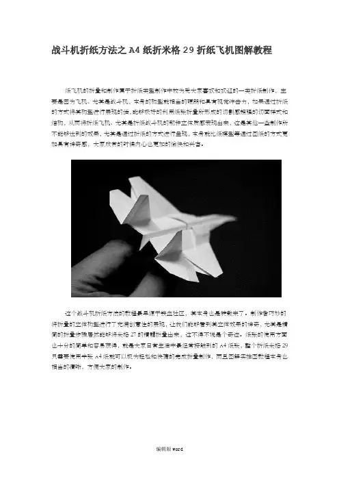
纸飞机的折叠和制作属于折纸类型制作中较为受大家喜欢和欢迎的一类折纸制作,主要是因为飞机、尤其是战斗机,本身的构型就相当的硬朗和具有视觉冲击力,如果通过折纸的方式将其构型进行展现的话,能够极好的利用纸张折叠所形成的切割感超强的切面样式和结构,从而将折纸飞机、尤其是折纸战斗机的那种立体质感表现出来,这是其他一些制作所不能够达到的效果,尤其是通过折纸的方式进行呈现,本身就比纸模型等通过图纸的方式更加具有神奇感,大家欣赏的时候内心也更加的愉快和兴奋。
这个战斗机折纸方法的教程最早源于铁血社区,其本身也是转载来了。
制作者巧妙的将折叠的立体构型进行了充满创意性的展现,让我们能够看到其立体效果的神奇,尤其是精简的折叠步骤居然能够将米格27的精髓折叠出来,这不得不说是个奇迹。
纸张的使用方面也十分的简单和容易获得,就是大家日常生活中最经常接触到的A4纸张,整个折纸米格29只需要使用半张A4纸就可以极为轻松和快捷的完成折叠制作,而且图解实拍图教程本身也相当的清晰,方便大家的制作。
虽然这个折纸飞机从构型上看起来和传统的折纸飞机有着很大的不同,但是其基本的折法上来看和传统的折纸飞机制作方法还是相当类似的,尤其是在前部结构和一些对称结构的折叠方面,这个折纸飞机基本上是在传统的折纸飞机基础上完成制作的。
不过由于其本身是战斗机折纸方法的一个展现,自然在许多细节上还是有所不同的,这也造就了这个折纸制作能够如此逼真的模仿真实的米格29,也让我们有机会去学习这样一个造型独特而又充满视觉冲击力的折纸飞机制作。
(此文档部分内容来源于网络,如有侵权请告知删除,文档可自行编辑修改内容,
供参考,感谢您的配合和支持)。