传感器仿真软件使用说明书
- 格式:doc
- 大小:5.22 MB
- 文档页数:42

传感器仿真软件使用说明书The Standardization Office was revised on the afternoon of December13, 2020THSRZ-2型传感器系统综合实验装置仿真软件使用说明书THSRZ-2型传感器系统综合实验装置仿真软件 ................. 错误!未定义书签。
实验一属箔式应变片――单臂电桥性能实验。
................. 错误!未定义书签。
实验二金属箔式应变片――半桥性能实验 ......................... 错误!未定义书签。
实验三金属箔式应变片――全桥性能实验 ......................... 错误!未定义书签。
实验四直流全桥的应用――电子秤实验 ............................. 错误!未定义书签。
实验五交流全桥的应用――振动测量实验 ......................... 错误!未定义书签。
实验六扩散硅压阻压力传感器差压测量实验 ..................... 错误!未定义书签。
实验七差动变压器的性能实验 ............................................. 错误!未定义书签。
实验八动变压器零点残余电压补偿实验 ............................. 错误!未定义书签。
实验九励频率对差动变压器特性的影响实验 ..................... 错误!未定义书签。
实验十差动变压器的应用――振动测量实验 ..................... 错误!未定义书签。
实验十一电容式传感器的位移特性实验 ............................. 错误!未定义书签。
实验十二容传感器动态特性实验 ......................................... 错误!未定义书签。

运动传感器软件使用技巧第一章使用前的准备在使用运动传感器软件之前,有几个准备步骤是非常重要的。
首先,确保您的设备上已安装了最新版本的运动传感器软件。
其次,将您的设备与传感器连接,并确保传感器已经处于正常工作状态。
最后,清理和准备您的工作区域,以确保可以正常感应到运动并避免不必要的干扰。
第二章传感器位置选择正确选择传感器的位置对于准确捕捉运动至关重要。
传感器通常应放置在需要监测运动的区域中,并与被测物体保持适当的距离。
如果传感器与被测物体之间的距离太远,它可能无法捕捉到细微的动作。
相反,如果距离太近,传感器可能会因为过于灵敏而捕捉到不必要的噪声信号。
第三章设置灵敏度大多数运动传感器软件提供了调整灵敏度的选项。
根据实际需求,您可以根据监测对象的大小和所需的运动范围来设置灵敏度。
如果您需要监测微小的运动,可以将灵敏度调至较高。
相反,如果您只需要监测较大的运动,可以将灵敏度调低。
通过适当调整灵敏度,您可以确保获得最准确的运动数据。
第四章数据记录和分析运动传感器软件通常提供了数据记录和分析的功能。
在开始使用传感器之前,确保已经设置好数据记录的选项,并选择合适的存储位置。
一旦传感器开始监测运动,软件将会记录相应的数据,包括时间、位置、运动方向等。
您可以使用这些数据进行进一步的分析,例如创建运动趋势图或比较不同时间段的运动数据。
第五章实时监控和警报许多运动传感器软件具备实时监控和警报功能。
这意味着您可以在监测期间实时查看运动并接收警报通知。
通过充分利用这些功能,您可以及时发现并采取必要的行动。
例如,您可以设置警报,当传感器监测到不寻常的运动时,软件将向您发送警报通知,以便您能够立即采取适当的措施。
第六章故障排除和维护有时,在使用运动传感器软件过程中可能会遇到一些问题。
在出现故障或异常情况时,您可以尝试一些基本的故障排除步骤。
首先,确认传感器是否正确连接并处于工作状态。
其次,检查传感器周围是否有干扰物,如灯光、电子设备或其他手持设备。

M5600/U5600 Software Manual Wireless Pressure TransducersContents1 Introduction Description 32 Manual Smartphone/Tablet Software Installation and Operation Manual 33 Manual Windows Version Software Installation and Operation Manual 44 Protocol Software Protocol Specification 161 IntroductionThe M5600 and U5600 pressure transducers use standard 2.4GHz wireless communication tag. The long battery life and integration design make these transducers a perfect fit for many industrial and commercial applications including marine, residential, campers, water, hydraulic, irrigation, pool, medical and sprinkler systems, or anywhere you would need to monitor pressure without the need for wires.By installing the Windows® version software on your PC or embedding the wireless signal in your integrated system, you can monitor pressure and temperature in real time.2 Smartphone/Tablet Software Installation1. Download and install the “TE Sensor Tag” app for iOS or Android™ from the Apple App Store or Google Play Store.2. Install the battery into the transducer.3. Turn on standard 2.4GHz wireless communication tag for smartphone/tablet.4. Run “TE Sensor Tag” app on smartphone/tablet and it will start searching for the transducer.5. Select the transducer (M5600 or U5600) found by the app to pair it to your smartphone/tablet.6. Once paired, the pressure and temperature charting will begin automatically. Data is collected every 5 seconds (programmed for bestbattery life).3 Windows Version Software Installation and Operation Manual Hardware & System Requirement∙PC with USB serial port support∙USB Dongle: BT900-US∙Operation system: Windows XP, Windows 7 or above∙Microsoft .NET Framework4.0 or aboveDongle Installation and Programming1. Insert the USB Dongle (BT900-US) into the USB socket of the PC.The PC will install the related USB drivers automatically.2. After installing FT232R USB UART, open the PC’s Device Manager and check if the USB Dongle has the port number assigned asbelow (COM5 in this example):If not assigned, then it is necessary to install the FTDI FT232 USB Serial Converter Driver following instructions from the below link: https:///tutorials/how-to-install-ftdi-drivers/windows---in-depthVerify COM port is assigned to the Dongle in the Device Manager before proceeding to the next step.3. Copy Window’s client software “TESS-M5600_U5600_Software.zip” to the PC and unzip it. Double-click to run UwTerminal in folder:TESS 5600\UwTerminal\. User interface should display as below:4. Click “Accept” to enter the configuration interface. Select the proper COM port where the Dongle is installed and leave the others atdefault settings.Then click “OK” to enter the command-line interface:5. Input “at &F *” (at space &F space *) and press “Enter”. The screen will display “ FFS Erased, Rebooting…”Close the window by clicking the “X” at the upper right corner.6. Run “BT900UartFwUpgrade.exe” in folder: TESS 5600\BT900_9.1.10.3 to update the firmware. Follow these steps: Press “OK” →specify the correct COM port →press “OK” → press “Start Upgrade” → let it run until finish →pressing “Quit.”7. Remove the USB Dongle and re-insert, repeat above steps 3 & 4.Input “at I 3” and press “Enter,” displaying “9.1.10.3” which is the latest version of the firmware.Input “at &F *” and press “Enter.” Screen will display “FFS Erased, Rebooting…”Input “at+dir” and press “Enter.”8. Right-click inside the window and click “load precompiled BASIC”After the “Open” window pops up, select “smartZ.umc” in folder “TESS 5600\” and press “Open”Text will scroll and after 1-2 minutes, it will display “DONE.”Close the “UwTerminal” window. Remove the USB Dongle and re-insert.Monitoring Software Operation Manual1. Double-click to run TESS 5600 for Windows in folder: TESS 5600\source\bin\Release\. The client software user interface shoulddisplay as below. Certain explanations can be found when moving the cursor onto the words.More explanations are provided as below:2. Ensure the Port Name matches the COM number in the Device Manager. Click the “Start” button, and then a “Scan” window will popup to search for available wireless devices. Double-click the MAC number matching the target device to select it.3. The software will start receiving and recording data on battery level and real-time pressure and temperature.Clicking the “Stop” button will stop the data taking process.4. When “Data Logging” is enabled and the interval set, a “Save“ window will pop up. When clicking the “S tart” button, all data will besaved in the folder appointed by the user (default: \\TESS\\data\\) as a *.dat file which can be opened with MS Excel.The “Date Time“ column can be formatted to display seconds as shown below:4 Software Protocol SpecificationUUID for the M5600/U5600 is available, which allows the user to compile their own program to recognize the sensor’s wireless signal and detect pressure, temperature and battery capacity.T is a 16 bits signed word, equals 0x7FFF if erroneous.P, Pmin and Pmax are 32 bits signed words, equal 0x7FFFFFFF if erroneous.T is a temperature value with 0.01°C resolution.P, Pmin and Pmax are pressure values with 0.1Pa resolutionCONVERSIONTemperature (°C) = T / 100Pressure (Pa) = P / 10Pressure (Psi) = P / 10 / 6894.7Battery Service:0% to 100% represents a supply voltage from 2.0V to 3.0V with 1%/bit resolution. STATUSNORTH AMERICA EUROPE ASIAMeasurement Specialties, Inc., a TE Connectivity company 45738 Northport Loop West Fremont, CA 94538Tel: +1 800 767 1888Fax: +1 510 498 1578************************MEAS France SAS,a TE Connectivity company26 Rue des Dames78340 Les Clayes-sous-Bois, FranceTel: +33 (0) 130 79 33 00Fax: +33 (0) 134 81 03 59************************Measurement Specialties (China) Ltd.,a TE Connectivity companyNo. 26 Langshan RoadShenzhen High-Tech Park (North) Nanshan District,Shenzhen, 518057ChinaTel: +86 755 3330 5088Fax: +86 755 3330 5099************************/sensorsolutionsAndroid is a trademark of Google Inc.Google Play is a trademark of Google Inc.iOS is a trademark or registered trademark of Cisco in the U.S. and other countries and is used under license.Microsoft, Encarta, MSN, and Windows are either registered trademarks or trademarks of Microsoft Corporation in the United States and/or other countries.Android and Windows are trademarks of their respective owners.The Bluetooth® word mark and logos are registered trademarks owned by the Bluetooth SIG, Inc. and any use of such marks by TE Connectivity is under license. Other trademarks and trade names are those of their respective owners.Measurement Specialties Inc., a TE Connectivity company.Measurement Specialties (MEAS), American Sensor Technologies (AST), TE Connectivity, TE Connectivity (logo) and EVERY CONNECTION COUNTS are trademarks. All other logos, products and/or company names referred to herein might be trademarks of their respective owners.The information given herein, including drawings, illustrations and schematics which are intended for illustration purposes only, is believed to be reliable. However, TE Connectivity makes no warranties as to its accuracy or completeness and disclaims any liability in connection with its use. TE Connectivity‘s obligations shall only be as set forth in TE Connectivity‘s Standard Terms and Conditions of Sale for this product and in no case will TE Connectivity be liable for any incidental, indirect or consequential damages arising out of the sale, resale, use or misuse of the product. Users of TE Connectivity products should make their own evaluation to determine the suitability of each such product for the specific application.© 2016 TE Connectivity Ltd. family of companies All Rights Reserved.Rev 02016/04/05。
无线传感器网络仿真软件用户手册2014年12月1日目录1. 简介 (1)1.1. 背景 (1)1.2. 软件运行环境 (1)1.3. 使用场景 (2)1.4. 试用版使用限制 (2)2. 安装 (2)2.1. 双击安装程序 (2)2.2. 安装向导 (3)2.3. 选择安装目录 (3)2.4. 选择是否建立开始菜单和创建快捷方式 (4)2.5. 安装 (4)2.6. 安装完成 (5)2.7. Atos-SensorSim快捷方式 (5)2.8. 安装目录中的文件夹 (7)2.9. Atos-SensorSim主界面 (7)3. Atos-SensorSim使用 (8)3.1. 网络管理 (8)3.1.1. 生成网络 (8)3.1.2. 查看生成网络的拓扑 (8)3.1.3. 修改生成网络的节点默认通信半径 (9)3.1.4. 显示网络节点属性 (9)3.1.5. 修改网络节点属性 (10)3.1.6. 增加网络节点 (10)3.1.7. 删除网络节点 (11)3.1.8. 网络显示缩放 (12)3.1.9. 保存生成的网络 (12)3.1.10. 打开保存的网络文件 (13)3.1.11. 创建网络文件分组 (13)3.1.12. 删除网络文件分组 (15)3.1.13. 删除网络文件 (16)3.2. 无线传感器网络算法管理 (18)3.2.1. 显示系统目前导入的算法 (18)3.2.2. 开始算法演示 (18)3.2.3. 停止算法演示 (19)3.2.4. 显示算法运行的节点分布 (20)3.2.5. 显示算法的网络链接信息 (20)3.2.6. 显示算法的网络链路质量信息 (21)3.2.7. 显示算法运行过程中经过的路线 (21)3.2.8. 显示算法的查询结果信息 (22)3.2.9. 调节算法演示的运行速度 (22)3.2.10. 单步执行算法 (23)3.2.11. 查看算法运行参数 (24)3.2.12. 查看算法运行过程中发生的事件 (24)3.2.13. 查看算法运行过程中发生事件的数据通信量 (25)3.2.14. 查看算法运行过程中发生事件的能量消耗 (25)3.2.15. 查看算法运行过程中的总能量消耗 (26)3.2.16. 快速查看算法运行过程 (26)3.2.17. 创建算法分组 (27)3.2.18. 删除算法分组 (29)3.2.19. 删除算法 (31)3.3. 无线传感器网络实验管理 (31)3.3.1. 显示系统中已保存的实验 (31)3.3.2. 查看实验 (32)3.3.3. 查看实验网络 (32)3.3.4. 查看实验算法 (33)3.3.5. 运行实验 (33)3.3.6. 创建实验分组 (34)3.3.7. 删除实验分组 (35)3.3.8. 删除实验 (37)无线传感器网络仿真软件用户手册1.简介1.1. 背景由于传感器网络及其算法的复杂性,传感器网络中的绝大多数算法的性能无法通过理论分析得到。
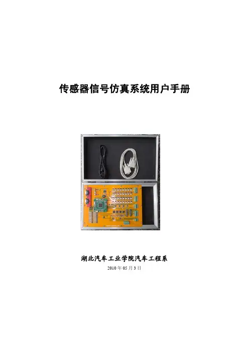
传感器信号仿真系统用户手册湖北汽车工业学院汽车工程系2010年05月3日目 录一系统概述 (1)二系统硬件使用说明 (2)2.1系统基本结构概述 (2)2.2系统电源状态指示 (2)2.3系统工作状态指示 (3)2.4RS-232串行通讯接口 (3)2.5MC9S12XDT256最小应用系统 (4)2.6系统外部接口1 (4)2.7系统外部接口2 (4)2.8系统外部接口3 (5)2.9系统外部接口4 (5)2.10系统外部接口5 (6)2.11系统外部接口6 (6)三ABHS软件使用说明 (8)3.1软件安装 (8)3.2用户身份验证及注册 (9)3.3参数设置 (10)3.4在线编程功能 (12)3.5写标定值功能 (13)3.6示波器功能 (23)四HEV调试功能 (25)4.1通讯参数设置 (25)4.2启动检测功能 (26)4.3开关量信号控制 (27)4.4模拟量信号控制 (27)4.5脉冲量信号控制 (28)4.6输入信号检测 (28)4.7CAN网络调试 (29)五发动机硬件在环仿真功能 (30)5.1通讯参数设置 (30)5.2启动检测功能 (31)5.3开关量信号检测 (32)5.4模拟量信号检测 (32)5.5脉冲量信号检测 (21)5.6输入信号检测 (21)5.7发动机类型选择 (214)六CAN+通用调试 (36)6.1通讯参数设置 (36)6.2启动检测功能 (37)6.3开关量信号控制 (38)6.4模拟量信号控制 (38)6.5脉冲量信号控制 (39)6.6开关量输入信号检测 (39)6.7模拟量输入信号检测 (40)6.8脉冲量输入信号检测 (40)6.9CAN总线调试 (41)七系统MAP标定 (42)八系统外部接口定义 (58)8.1HEV调试模块外部接口定义 (58)8.2发动机硬件在环仿真模块外部接口定义 (60)8.3CAN+通用模块外部接口定义 (62)一、系统概述传感器信号仿真系统用于模拟各类型车辆常用传感器信号,一般配合其他目标控制系统使用,是汽车电子技术应用中理想的离线调试工具,尤其适合于复杂控制系统的初步开发、设计应用及控制策略的分析和验证。

XY2型应变传感器模拟器使用说明书(1.03版)第一章技术参数目录第一章技术参数 (1)1.1 型号 (1)1.2 技术指标 (1)1.3 仪表外型 (2)第二章工作原理 (5)第三章使用操作方法 (7)3.1 仪器的功能 (7)3.2 接线方法 (8)3.3 键盘 (10)3.4 键功能说明 (11)3.5 模拟器的操作 (12)3.5.1 按步长逐级输出 (12)3.5.2 按输入值输出信号 (12)3.5.3 按设定范围逐级输出信号 (13)3.5.4 由上位机控制模拟器的输出 (14)3.5.5 改变激励电压范围 (15)3.5.6 设置工作参数 (15)3.5.7 测量温度 (17)3.5.8 编程功能 (18)3.5.9 运行用户程序 (19)第四章设置与校准 (20)4.1 零点校准 (20)4.2 满程校准 (21)4.3 线性校准(考虑是否保留) (22)4.4 温度特性和电压影响校准 (24)4.5 激励电压校准 (26)4.6 外接直流电源电压校准 (28)目录4.8 设置通讯功能 (29)4.9 调整对比度 (31)4.10 检查参数 (31)4.10.1 外接电源状态 (32)4.10.2 零点DA码 (32)4.10.3 满量程DA码 (32)4.10.4 零点温度影响 (33)4.10.5 满量程温度影响 (33)4.10.6 激励电压影响 (33)4.10.7 激励电压计量参数 (34)4.10.8 共模电压计量参数 (34)4.10.9 非线性修正值 (34)第五章编制用户程序 (35)5.1 XY2的用户程序指令系统 (35)5.2 键盘编程方法 (37)5.3 计算机编程 (39)5.4 计算机编程语法 (45)5.5 程序实例 (45)第六章错误提示信息 (59)第七章使用注意事项 (60)第八章常见故障的排除............................. 0亲爱的用户:在使用仪表前,敬请认真阅读使用说明书。

PSEN cs1.1n}PSEN sensor technologyThis document is a translation of the original document.All rights to this documentation are reserved by Pilz GmbH & Co. KG. Copies may be made for internal purposes. Suggestions and comments for improving this documentation will be gratefully received.Source code from third-party manufacturers or open source software has been used for some components. The relevant licence information is available on the Internet on the Pilz homepage.Pilz®, PIT®, PMI®, PNOZ®, Primo®, PSEN®, PSS®, PVIS®, SafetyBUS p®,SafetyEYE®, SafetyNET p®, the spirit of safety® are registered and protected trademarks of Pilz GmbH & Co. KG in some countries.SD means Secure DigitalUsing the documentation4 Definition of symbols4Safety regulations5 Safety assessment5 Use of qualified personnel6 Warranty and liability6 Disposal6 For your safety7Operating distances8 Lateral and vertical offset9Accessories20IntroductionValidity of documentationThis documentation is valid for the product PSEN cs1.1n. It is valid until new documentation is published.This operating manual explains the function and operation, describes the installation and provides guidelines on how to connect the product.Using the documentationThis document is intended for instruction. Only install and commission the product if you have read and understood this document. The document should be retained for future ref-erence.Definition of symbolsInformation that is particularly important is identified as follows:NOTICEThis describes a situation in which the product or devices could be dam-aged and also provides information on preventive measures that can betaken. It also highlights areas within the text that are of particular import-ance.SafetyIntended useSafety function of safety switch:} 2 safety outputs, each of which supply a high signal when the actuator is in the safety switch's response range.The safety switch meets the requirements in accordance with:}EN 60947-5-3 with the actuator PSEN cs1.1 : PDDB}EN 62061: SIL CL 3}EN ISO 13849-1: PL e (Cat. 4)}EN ISO 14119: Coding level Low, Type4The safety switch may only be used with the corresponding actuator PSEN cs1.1.The safety level PL e (Cat. 4 )/SIL CL 3 is only achieved if}the safety outputs use 2-channel processing.The following is deemed improper use in particular:}Any component, technical or electrical modification to the product}Use of the product outside the areas described in this manual}Use of the product outside the technical details (see Technical details [ 16]).NOTICEEMC-compliant electrical installationThe product is designed for use in an industrial environment. The productmay cause interference if installed in other environments. If installed in otherenvironments, measures should be taken to comply with the applicablestandards and directives for the respective installation site with regard to in-terference.Safety regulationsSafety assessmentBefore using a unit it is necessary to perform a safety assessment in accordance with the Machinery Directive.Functional safety is guaranteed for the product as a single component. However, this does not guarantee the functional safety of the overall plant/machine. In order to achieve the re-quired safety level for the overall plant/machine, define the safety requirements for the plant/machine and then define how these must be implemented from a technical and organ-isational standpoint.Use of qualified personnelThe products may only be assembled, installed, programmed, commissioned, operated, maintained and decommissioned by competent persons.A competent person is a qualified and knowledgeable person who, because of their train-ing, experience and current professional activity, has the specialist knowledge required. To be able to inspect, assess and operate devices, systems and machines, the person has to be informed of the state of the art and the applicable national, European and international laws, directives and standards.It is the company’s responsibility only to employ personnel who}Are familiar with the basic regulations concerning health and safety / accident preven-tion,}Have read and understood the information provided in this description under "Safety"}Have a good knowledge of the generic and specialist standards applicable to the spe-cific application.Warranty and liabilityAll claims to warranty and liability will be rendered invalid if}The product was used contrary to the purpose for which it is intended}Damage can be attributed to not having followed the guidelines in the manual}Operating personnel are not suitably qualified}Any type of modification has been made (e.g. exchanging components on the PCB boards, soldering work etc.).Disposalin the safety-re-}In safety-related applications, please comply with the mission time TM lated characteristic data.}When decommissioning, please comply with local regulations regarding the disposal of electronic devices (e.g. Electrical and Electronic Equipment Act).For your safety}Do not remove the connector's protective cap until you are just about to connect the unit. This will prevent potential contamination.Unit features}Transponder technology for presence detection}Pilz coding type: Coded}Dual-channel operation} 2 safety outputs}LED display for:–State of the actuator–Supply voltage/fault} 4 directions of actuationFunction descriptionThe safety outputs may have a high or low signal, depending on the position of the actu-ator.In a safe condition there is a low signal at the safety outputs.State of the outputs:Block diagramOperating distancesLegend:Assured operating distance:15 mm }SaoTypical operating distance:21 mm }SoTypical release distance: 32 mm}SrAssured release distance: 40 mm }SarLateral and vertical offsetLegend[1]Hysteresis[2]Typical operating distance SO[3]Typical release distance Sr[4]Offset in mm[5]Operating distance in mm[6]Response rangeWiringPlease note:}Information given in the "Technical details" must be followed.}The power supply must meet the regulations for extra low voltages with protective sep-aration (SELV, PELV).}The inputs and outputs of the safety switch must have a protective separation to voltages over 60 VDC.}The supply voltage to the safety switch must be protected with a 2 A to 4 A quick-acting fuse.}Ensure the wiring and EMC requirements of IEC 60204-1 are met.Pin assignment, connector and cableThe wire colour also applies for the cable available from Pilz as an accessory.Connection to evaluation devicesMake sure that the selected evaluation device has the following property:}OSSD signals are evaluated through 2 channels with feasibility monitoringPlease note:}Information given in the Technical details [ 16] must be followed.Connection diagram, single connectionSuitable Pilz evaluation devices are, for example:}PNOZelog for safety gate monitoring}PNOZpower for safety gate monitoring}PNOZsigma for safety gate monitoring}PNOZ X for safety gate monitoring}PNOZmulti for safety gate monitoringConfigure the switch in the PNOZmulti Configurator with switch type 3.}PSS for safety gate monitoring with standard function block SB064, SB066 or FS_Safety Gate}PSSuniversal PLC for safety gate monitoring with function block FS_SafetyGateThe correct connection to the respective evaluation device is described in the operating manual for the evaluation device. Make sure that the connection is made in accordance with the specifications in the operating manual for the selected evaluation device.The connections to two evaluation devices are shown on the following pages, by way of ex-ample:}PNOZ s3 and}PNOZmultiPNOZ s3PNOZmultiI0I1Legend:I0Input OSSDI1Input OSSDTeaching in the actuatorAny Pilz actuator PSEN cs1.1) is detected as soon as it is brought into the response range. Installation}The safety switch and actuator should be installed opposite each other in parallel.–Make sure that the actuator is aligned to the marking on the sensor that guarantees the operating distance required by the plant design (see Operatingdistances [ 8]).}Safety switches and actuators should be permanently secured using M5 safety screws with a flat head (e.g. M5 cheese-head or pan head screws).}Protect the actuator from contamination.}Torque setting: Please note the information provided under Technical details [ 16]. }The distance between two safety switches must be maintained (see Technical details [ 16]).}Make sure that the safety switch and actuator cannot be used as an end stop.}Please note the installation measures in accordance with EN ISO 14119 for a safety switch design 4 and with level of coding Low}For simpler installation, the mounting brackets (see Order reference for Accessories [ 20]) can be used.}If using angled connector plugs, note the defined angle of the cable routing.Procedure:Fig.: Sensing faces on the sensor1.Drill holes (for M5 screws) in the mounting surface to secure the actuator and sensor(see Dimensions in mm [ 16]).e a screw to fix the sensor to the mounting surface.Make sure that the sensor marking that is be used for operation can be operated using the actuator from the right side.3.Do not fully tighten the second screw on the safety switch.e a screw to fix the actuator to the mounting surface.Make sure that the actuator with the printed side points towards the marking on the sensor.5.Do not fully tighten the second screw on the actuator.6.Align the safety switch and tighten the screws.7.Align the actuator and tighten the screws.Adjustment}The stated operating distances (see Technical details [ 16]) only apply when the safety switch and actuator are installed facing each other in parallel. Operating dis-tances may deviate if other arrangements are used.}Note the maximum permitted lateral and vertical offset (see Operating distances [ 8] and Lateral and vertical offset [ 9]).OperationNOTICEThe safety function should be checked after initial commissioning and eachtime the plant/machine is changed. The safety functions may only bechecked by qualified personnel.Check the function of the safety switch before commissioning.Status indicators:}"POWER/Fault" LED lights up green: The unit is ready for operation}"Safety Gate" LED lights up yellow: Actuator is within the response range }"Input" LED lights up yellow: Device is error-freeFault indicator:}"POWER/Fault" LED lights up red: Error message.Flashing codes for fault diagnostics are output to the "Safety Gate" and "Input" LEDs (see Error display through flashing codes).Remedy: Rectify fault and interrupt power supply.Error display through flashing codesThe "Safety Gate" and "Input" LEDs send flash signals; an error code can be established from the number and sequence. The "Power/Fault" LED illuminates red.Each error code is indicated by three short flashes of the "Input" or "Safety Gate" LED. After a longer pause, the LED will then flash at one second intervals. The number of LED flashes corresponds to a digit in the error code. The error code can consist of up to 3 digits. The digits are separated by a longer period without flashing. The entire sequence is con-stantly repeated.Number of flashes 1 2 3 4 5 6 7 8 9 10 11 12 13 14 15 16Decimal error code 1 2 3 4 5 6 7 8 9 10 11 12 13 14 15 0Example:Error code 1,4,1:Flash frequency of the "Safety Gate" or "Input" LEDII VI IVIIIMeaning of flash frequency:Table of error codesOther flashing codes signal an internal error. Remedy: Change device.Dimensions in mmTechnical detailsSensor's mode of operation Transponder Coding level in accordance with EN ISO 14119LowDesign in accordance with EN ISO 141194 Classification in accordance with EN 60947-5-3PDDBVoltage24 VKind DCVoltage tolerance-20 %/+20 % Output of external power supply (DC) 2 WMax. inrush current at UB0,12 A Max. switching frequency 3 HzNo-load, PNOZ with relay contacts40 nFPNOZmulti, PNOZelog, PSS70 nFSwitching current per output500 mABreaking capacity per output12 WPotential isolation from system voltage NoShort circuit-proof yesResidual current at outputs10 µAVoltage drop at OSSDs3,5 VLowest operating current0 mASwitch-on delayafter UB is applied 1 sActuator typ.80 msActuator max.150 msDelay-on de-energisationActuator typ.40 msActuator max.260 msRisk time in accordance with EN 60947-5-3260 msSupply interruption before de-energisation20 msIn accordance with the standard EN 60068-2-14 Temperature range-25 - 70 °C Storage temperatureIn accordance with the standard EN 60068-2-1/-2 Climatic suitabilityIn accordance with the standard EN 60068-2-78 Humidity93 % r. h. at 40 °C EMC EN 60947-5-3 VibrationIn accordance with the standard EN 60947-5-2Frequency10 - 55 HzAmplitude 1 mmShock stressIn accordance with the standard EN 60947-5-2Acceleration30gDuration11 msOvervoltage category IIIPollution degree3Rated insulation voltage75 VRated impulse withstand voltage0,8 kVProtection typeOperating distancesAssured operating distance Sao15 mmTypical operating distance So21 mmAssured release distance Sar40 mmTypical release distance Sr32 mmRepetition accuracy switching distances10 %Change of operating distance with temperaturechanges+-0,01mm/°CTyp. Hysteresis 3 mmMin. distance between safety switches400 mmSensor flush installation in accordance with EN60947-5-2Yes, follow installation guidelines Connection type M12, 5-pin male connector MaterialTop PBTMax. torque setting for fixing screws 1 NmDimensionsHeight75 mmWidth40 mmDepth40 mmActuator dimensionsHeight11 mmWidth40 mmDepth40 mmWeight of safety switch130 gWeight of actuator20 gWeight150 gWhere standards are undated, the 2016-10 latest editions shall apply.Safety characteristic dataNOTICEYou must comply with the safety-related characteristic data in order to achieve the required safety level for your plant/machine.2-ch. OSSD PL e Cat. 4SIL CL 34,10E-09–1,10E-0420All the units used within a safety function must be considered when calculating the safety characteristic data.Supplementary dataRadio approvalFCC ID: IC:FCC/IC-Requirements:This product complies with Part 15 of the FCC Rules and with Industry Canada licence-exempt RSS standards. Operation is subject to the following two conditions: 1) this product may not cause harmful interference, and2) this product must accept any interference received, including interference that may cause undesired operation.Changes or modifications made to this product not expressly approved by Pilz may void the FCC authorization to operate this equipment.Order referenceSystemAccessoriesInstallation materialsPSEN screw M5x10 10pcs Safety screws made from stainless steel with one-way slot 540 311PSEN screw M5x20 10pcs Safety screws made from stainless steel with one-way slot 540 312PSEN cs1/2 bracket cable fixMechanical protection against defeat, protecting against unau-thorised cable disconnection or damage for safety switches PSENcode cs1/2, PSENcode cs5/6 M12, PSENslock532 112CableOperating Manual PSEN cs1.1n 22178-EN-0521PDP67 F 8DI ION Decentralised input module IP67 for PNOZmulti773 600EC declaration of conformityThis product/these products meet the requirements of the directive 2006/42/EC for ma-chinery of the European Parliament and of the Council. The complete EC Declaration ofConformity is available on the Internet at /downloads.Representative: Norbert Fröhlich, Pilz GmbH & Co. KG, Felix-Wankel-Str. 2, 73760 Ost-fildern, GermanyThe Best of German EngineeringPartner of:SupportTechnical support is available from Pilz round the clock. Americas Brazil+55 11 97569-2804Canada+1 888-315-PILZ (315-7459)Mexico+52 55 5572 1300USA (toll-free)+1 877-PILZUSA (745-9872)Asia China+86 21 60880878-216 Japan+81 45 471-2281South Korea +82 31 450 0680Australia +61 3 95600621Europe Austria+43 1 7986263-0Belgium, Luxembourg +32 9 3217575France+33 3 88104000Germany+49 711 3409-444Ireland+353 21 4804983Italy, Malta +39 0362 1826711Scandinavia +45 74436332Spain+34 938497433Switzerland +41 62 88979-30The Netherlands +31 347 320477Turkey+90 216 5775552United Kingdom +44 1536 462203You can reach our international hotline on: +49 711 3409-444 ****************C M S E ®, I n d u r a N E T p ®, P A S 4000®, P A S c a l ®, P A S c o n fig ®, P i l z ®, P I T ®, P L ID ®, P M C p r i m o ®, P M C p r o t e g o ®, P M C t e n d o ®, P M D ®, P M I ®, P N O Z ®, P r i m o ®, P SE N ®, P S S ®, P V I S ®, S a f e t y B U S p ®, S a f e t y E Y E ®, S a f e t y N E T p ®, T H E S P I R I T OF S A F E T Y ® a r e r e g i s t e r e d a n d p r o t e c t e d t r a d e m a r k s o f P i l zG m bH & C o . K G i n s o m e c o u n t r i e s . W e w o u l d p o i n t o u t t h a t p r o d u c t f e a t u r e s m a y v a r y f r o m t h e d e t a i l s s t a t e d i n t h i s d o c u m e n t , d e p e n d i n g o n t h e s t a t u s a t t h e t i m e o f p u b l i c a t i o n a n d t h e s c o p e o f t h e e q u i p m e n t . W e a c c e p t n o r e s p o n s i b i l i t y f o r t h e v a l i d i t y , a c c u r a c y a n d e n t i r e t y o f t h e t e x t a n d g r a p h i c s p r e s e n t e d i n t h i s i n f o r m a t i o n . P l e a s e c o n t a c t o u r T e c h n i c a l S u p p o r t i f y o u h a v e a n y q u e s t i o n s .Pilz develops environmentally-friendly products using ecological materials and energy-saving technologies. O ces and production facilities are ecologically designed, environmentally-aware and energy-saving. So Pilz o ers sustainability, plus the security of using energy-e cient products and environmentally-friendly solutions.Pilz GmbH & Co. KG Felix-Wankel-Straße 2 73760 Ostfildern, Germany Tel.: +49 711 3409-0 Fax: +49 711 3409-133 *************200X X X X -E N -0X 0-0-2-3-000, 2017-00 P r i n t e d i n G e r m a n y © P i l z G m b H & C o . K G , 201722178-E N -05, 2016-11 P r i n t e d i n G e r m a n y © P i l z G m b H & C o . K G , 2015。
目录THSRZ-2型传感器系统综合实验装置仿真软件 (2)实验一属箔式应变片――单臂电桥性能实验。
(3)实验二金属箔式应变片――半桥性能实验 (5)实验三金属箔式应变片――全桥性能实验 (6)实验四直流全桥的应用――电子秤实验 (7)实验五交流全桥的应用――振动测量实验 (8)实验六扩散硅压阻压力传感器差压测量实验 (10)实验七差动变压器的性能实验 (11)实验八动变压器零点残余电压补偿实验 (12)实验九励频率对差动变压器特性的影响实验 (14)实验十差动变压器的应用――振动测量实验 (15)实验十一电容式传感器的位移特性实验 (17)实验十二容传感器动态特性实验 (18)实验十三直流激励时霍尔式传感器的位移特性实验 (19)实验十四流激励时霍尔式传感器的位移特性实验 (20)实验十五霍尔测速实验 (21)实验十六霍尔式传感器振动测量实验 (22)实验十七磁电式转速传感器的测速实验 (24)实验十八压电式传感器振动实验 (26)实验十九电涡流传感器的位移特性实验 (27)实验二十被测体材质、面积大小对电涡流传感器的特性影响实验 (28)实验二十一电涡流传感器测量振动实验 (31)实验二十二光纤传感器的位移特性实验 (32)实验二十三光纤传感器的测速实验 (33)实验二十四光纤传感器测量振动实验 (34)实验二十五光电转速传感器的转速测量实验 (36)实验二十六PT100温度控制实验 (37)实验二十七集成温度传感器的温度特性实验 (38)实验二十八铂电阻温度特性实验 (39)实验二十九热电偶测温实验 (40)实验三十E型热电偶测温实验 (41)实验三十一热电偶冷端温度补偿实验 (42)实验三十二气敏传感器实验 (43)实验三十三湿敏传感器实验 (44)实验三十四转速控制实验 (46)THSRZ-2型传感器系统综合实验装置仿真软件一、概述本仿真软件主要是针对THSRZ-2型传感器系统综合实验装置配套的上位机软件而开发的,与“物理”、“传感器技术”、“工业自动化控制”、“非电测量技术与应用”、“工程检测技术与应用”等课程的教学实验配套使用,提供了真正实验前的模拟实验。

THSRZ-2型传感器系统综合实验装置仿真软件使用说明书THSRZ-2型传感器系统综合实验装置仿真软件 (2)实验一属箔式应变片――单臂电桥性能实验。
(3)实验二金属箔式应变片――半桥性能实验 (5)实验三金属箔式应变片――全桥性能实验 (6)实验四直流全桥的应用――电子秤实验 (7)实验五交流全桥的应用――振动测量实验 (8)实验六扩散硅压阻压力传感器差压测量实验 (10)实验七差动变压器的性能实验 (11)实验八动变压器零点残余电压补偿实验 (11)实验九励频率对差动变压器特性的影响实验 (13)实验十差动变压器的应用――振动测量实验 (14)实验十一电容式传感器的位移特性实验 (15)实验十二容传感器动态特性实验 (16)实验十三直流激励时霍尔式传感器的位移特性实验 (17)实验十四流激励时霍尔式传感器的位移特性实验 (18)实验十五霍尔测速实验 (19)实验十六霍尔式传感器振动测量实验 (20)实验十七磁电式转速传感器的测速实验 (22)实验十八压电式传感器振动实验 (24)实验十九电涡流传感器的位移特性实验 (24)实验二十被测体材质、面积大小对电涡流传感器的特性影响实验 (26)实验二十一电涡流传感器测量振动实验 (28)实验二十二光纤传感器的位移特性实验 (29)实验二十三光纤传感器的测速实验 (30)实验二十四光纤传感器测量振动实验 (32)实验二十五光电转速传感器的转速测量实验 (34)实验二十六 PT100温度控制实验 (34)实验二十七集成温度传感器的温度特性实验 (36)实验二十八铂电阻温度特性实验 (36)实验二十九热电偶测温实验 (38)实验三十 E型热电偶测温实验 (38)实验三十一热电偶冷端温度补偿实验 (39)实验三十二气敏传感器实验 (40)实验三十三湿敏传感器实验 (41)实验三十四转速控制实验 (43)THSRZ-2型传感器系统综合实验装置仿真软件一、概述本仿真软件主要是针对THSRZ-2型传感器系统综合实验装置配套的上位机软件而开发的,与“物理”、“传感器技术”、“工业自动化控制”、“非电测量技术与应用”、“工程检测技术与应用”等课程的教学实验配套使用,提供了真正实验前的模拟实验。
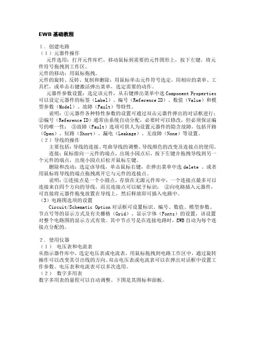
EWB基础教程1.创建电路(1)元器件操作元件选用:打开元件库栏,移动鼠标到需要的元件图形上,按下左键,将元件符号拖拽到工作区。
元件的移动:用鼠标拖拽。
元件的旋转、反转、复制和删除:用鼠标单击元件符号选定,用相应的菜单、工具栏,或单击右键激活弹出菜单,选定需要的动作。
元器件参数设置:选定该元件,从右键弹出菜单中选Component Properties 可以设定元器件的标签(Label)、编号(Reference ID)、数值(Value)和模型参数(Model)、故障(Fault)等特性。
说明:①元器件各种特性参数的设置可通过双击元器件弹出的对话框进行;②编号(Reference ID)通常由系统自动分配,必要时可以修改,但必须保证编号的唯一性;③故障(Fault)选项可供人为设置元器件的隐含故障,包括开路(Open)、短路(Short)、漏电(Leakage)、无故障(None)等设置。
(2)导线的操作主要包括:导线的连接、弯曲导线的调整、导线颜色的改变及连接点的使用。
连接:鼠标指向一元件的端点,出现小园点后,按下左键并拖拽导线到另一个元件的端点,出现小园点后松开鼠标左键。
删除和改动:选定该导线,单击鼠标右键,在弹出菜单中选delete 。
或者用鼠标将导线的端点拖拽离开它与元件的连接点。
说明:①连接点是一个小圆点,存放在无源元件库中,一个连接点最多可以连接来自四个方向的导线,而且连接点可以赋予标识;②向电路插入元器件,可直接将元器件拖曳放置在导线上,然后释放即可插入电路中。
(3)电路图选项的设置Circuit/Schematic Option对话框可设置标识、编号、数值、模型参数、节点号等的显示方式及有关栅格(Grid)、显示字体(Fonts)的设置,该设置对整个电路图的显示方式有效。
其中节点号是在连接电路时,EWB自动为每个连接点分配的。
2.使用仪器(1)电压表和电流表从指示器件库中,选定电压表或电流表,用鼠标拖拽到电路工作区中,通过旋转操作可以改变其引出线的方向。
无线传感器网络仿真软件用户手册2014年 12月 1日目录1. 简介 (1)1.1. 背景 (1)1.2. 软件运转环境 (1)1.3. 使用处景 (2)1.4. 试用版使用限制 (2)2. 安装 (2)2.1. 双击安装程序 (2)2.2. 安装导游 (3)2.3. 选择安装目录 (3)2.4. 选择能否成立开始菜单和创立快捷方式 (4)2.5. 安装 (4)2.6. 安装达成 (5)2.7. Atos-SensorSim 快捷方式 (5)2.8. 安装目录中的文件夹 (7)2.9. Atos-SensorSim 主界面 (7)3. Atos-SensorSim 使用 (8)3.1. 网络管理 (8)3.1.1. 生成网络 (8)3.1.2. 查察生成网络的拓扑 (8)3.1.3. 改正生成网络的节点默认通讯半径 (9)3.1.4. 显示网络节点属性 (9)3.1.5. 改正网络节点属性 (10)3.1.6. 增添网络节点 (10)3.1.7. 删除网络节点 (11)3.1.8. 网络显示缩放 (12)3.1.9. 保留生成的网络 (12)3.1.10. 翻开保留的网络文件 (13)3.1.11. 创立网络文件分组 (13)3.1.12. 删除网络文件分组 (15)3.1.13. 删除网络文件 (16)3.2. 无线传感器网络算法管理 (18)3.2.1. 显示系统目前导入的算法 (18)3.2.2. 开始算法演示 (18)3.2.3. 停止算法演示 (19)3.2.4. 显示算法运转的节点散布 (20)3.2.5. 显示算法的网络链接信息 (20)3.2.6. 显示算法的网络链路质量信息 (21)3.2.7. 显示算法运转过程中经过的路线 (21)3.2.8. 显示算法的查问结果信息 (22)3.2.9. 调理算法演示的运转速度 (22)3.2.11.查察算法运转参数 (24)3.2.12.查察算法运转过程中发生的事件 (24)3.2.13.查察算法运转过程中发惹祸件的数据通讯量 (25)3.2.14.查察算法运转过程中发惹祸件的能量耗费 (25)3.2.15.查察算法运转过程中的总能量耗费 (26)3.2.16.迅速查察算法运转过程 (26)3.2.17.创立算法分组 (27)3.2.18.删除算法分组 (29)3.2.19.删除算法 (31)3.3.无线传感器网络实验管理 (31)3.3.1.显示系统中已保留的实验 (31)3.3.2.查察实验 (32)3.3.3.查察实验网络 (32)3.3.4.查察实验算法 (33)3.3.5.运转实验 (33)3.3.6.创立实验分组 (34)3.3.7.删除实验分组 (35)3.3.8.删除实验 (37)1.简介1.1. 背景因为传感器网络及其算法的复杂性,传感器网络中的绝大部分算法的性能没法经过理论剖析获得。
传感器实验仪软件V9.0版使用说明简介本软件由浙江高联科技开发有限公司,专为传感器实验仪的数据采集通讯卡配套的应用软件。
以WINDOS操作系统为工作平台,为用户提供了全新的界面。
通过计算机串行口与传感器实验仪进行通信并采集实时数据,然后再对数据进行动态或静态处理和分析,并在屏幕上形成坐标曲线。
这些数据能以文件形式保存并在实验数据库中形成实验记录。
实验数据库具有数据管理功能,可对记录进行添加、删除、查询、编辑、打印等操作。
该软件还可以提取历史实验数据,并对这些数据进行分析和处理。
对于初学者实验用户来说,软件的操作十分方便。
V9.0在以前的版本上增加了示波器、双通道、频谱分析、失真度仪等功能,功能更加齐全。
注意:本软件在正版的Windows系统下正常运行,请安装和使用正版的Windows系统软件,对由于使用盗版Windows系统软件引起的软件操作和使用不正确或者不正常,本公司概不负责!另外,为了使您能更方便、更安全地使用本软件,建议在安装和使用本软件前,用杀毒软件对系统进行全面杀毒检查,确保系统的稳定性和安全性!软件制作、测试中已力求软件的稳定性和使用性能,但并不保证软件没有任何的错误!希望用户在发现错误或者对软件有什么操作不便时,请及时与本公司联系,我们会在最快的时间内给您满意的答复。
一、系统概述 (4)1、配套实验仪器: (4)2、微机: (4)3、主要功能: (4)4、操作系统平台和开发语言: (5)二、软件安装与删除 (6)1、安装 (6)2、删除 (11)三、软件使用说明: (13)1、窗口说明: (13)2、实验操作: (24)3、图形拉伸放大功能: (31)4、软件标定: (32)一、系统概述1、配套实验仪器:与本软件配套使用的是实验仪是浙江高联科技开发有限公司生产的传感器实验仪。
该类实验仪、实验台或模块部分设有应变传感器、霍尔传感器、压电式传感器、磁电式传感器、热电偶、热电阻、光纤、光电等各种传感器,并提供电桥、差动放大器、相敏检波器、移相器、滤波器、电荷放大器、光电转换器等测量电路,能做相关实验,采集卡外置,具有实时采样和数据通讯功能。
传感器3D虚拟仿真软件使用说明书12020年4月19日TianhuangTeaching Apparatus天煌教仪版本号:V1.0传感器及应用系列传感器3D虚拟仿真软件使用说明书天煌教仪浙江天煌科技实业有限公司CONTENTS 目录1.系统配置(推荐) (3)1.1 硬件运行环境 (3)1.2 软件运行环境 (3)2.系统构成 (3)2.1系统框架 (3)2.2系统简介 (4)3.使用操作 (4)3.1软件启动 (4)3.2传感32020年4月19日器 (5)3.2.1湿敏传感器主界面 (5)3.2.2产品说明界面 (6)3.2.3零件展示界面 (7)3.2.4装配演示界面 (8)3.2.5原理展示界面 (9)42020年4月19日5 2020年4月19日 使用说明书1.系统配置(推荐)1.1 硬件运行环境机型:PC 及兼容机;CPU 类型:Intel 酷睿双核 以上;RAM(内存)大小:1G 以上;HD(硬盘)空间:剩余空间 1G 以上;光盘驱动器:16 倍速以上;推荐显示分辨率与色彩:1280×1024 16 位色以上;独立显卡:512M 以上显存。
1.2 软件运行环境Windows XP 、Windows Vista 、Windows 7 .如有不清楚的地方请直接发E-mail 至或拨打电话 2.系统构成2.1 系统框架《传感器3D 虚拟仿真》软件系统框架如图2-1所示。
6 2020年4月19日图2-1 《传感器3D 虚拟仿真》软件系统框架结构2.2系统简介本系统采用全3D虚拟仿真技术,界面生动美观、易学易用,以此提高老师教学和学生学习的趣味性,加深学生对知识的理解和运用。
本系统经过产品说明、零件展示、装配演示、原理展示四个方面,讲述了霍尔传感器、压电传感器、湿敏传感器、气敏传感器、电涡流传感器、磁电传感器、差动电容传感器、差动变压器等八个常见传感器。
产品说明:从理论上简单介绍传感器的原理。
Accurate Timing in Sensor Network Simulation Muhammad Hamad Alizai, Olaf Landsiedel, Klaus WehrleDistributed Systems GroupRWTH Aachen{hamad.alizai, ndsiedel, klaus.wehrle}@rwth-aachen.deABSTRACTAccuracy, speed and scalability are the basic requirements of sensor network simulation. To comprehend the accurate behavior of resource constrained embedded systems such as sensor nodes it is important in simulations to model the time-dependent behavior of the system. In this paper we present our extensions of TOSSIM [2] – a widely used event-driven simulation environment for sensor networks – to enable its simulation models to capture the time-accurate behavior of sensor networks by exhibiting timing and interrupt properties of the platform dependent source-code. By mapping the device specific code with the simulation model, we can derive the timing of functional code blocks. As result of such a mapping it is possible to determine the time when a certain code block gets executed and the time the execution takes, eliminating the need of expensive cycle-accurate instruction level simulators with limited speed and restricted scalability.1.INTRODUCTIONSimulation indisputably remains one of the most important tools for analyzing, evaluating and validating system design. The importance of simulation is further aggravated for systems having an embedded nature, high deployment costs, or possessing unobservable fast interactions yet important to validate the system design. Sensor Networks with their distributed behavior, strenuous deployment requirements, constrained resources, and invisible and unpredictable interaction between the sensor nodes poses additional demands on their simulation.In the past few years a great deal of effort has been invested in the design and development of simulators for sensor networks to embrace the special requirements imposed by the highly distributed and dynamic nature of sensor networks. Unfortunately all these efforts have made compromises over different attributes of the simulation, for example, accuracy has been compromised over scalability and vice versa. SWAN [4], SensorSim [5], and SENS [6] are examples of sensor network simulators which compromise scalability over accuracy by using nonfigurative models of the sensor nodes. Such simulation models only contribute to quantify network delays, throughputs, packet collisions, power usage and the effect of several power management schemes [3]. However, these models do not reveal the timing and interrupt properties of applications, the operating systems, and hardware components.ATEMU [7] and Avrora [3] on the other hand are cycle-accurate instruction level simulators for sensor networks with the most expressive simulation models. Nevertheless, they compromise the scalability and performance/speed. ATEMU is 30 times slower than TOSSIM [3], and its poor performance limits its scalability to 120 nodes. Avrora shows better performance measures than ATEMU with reasonably good speed for small number of sensor network nodes but it is still 50% slower than TOSSIM. The performance measures of Avrora have been calculated on a 16 processor machine, not easily accessible to normal end-users and developers. Avrora exhibits typical performance bottlenecks of instruction level simulators when run on customary end-user machines, especially, when several avrora-monitors are enabled for detailed analysis of the sensor network behavior.Our goal is to provide time accurate simulation for sensor networks at the basic-block granularity (i.e. sequence of instructions with a single entry point, single exit point, and no internal branches) of the source code without compromising the speed and scalability, and hence eliminating the need to use expensive instruction level simulators. We extend TOSSIM to exhibit the timing and interrupt properties of sensor network code without destroying its performance and scalability advantages. 2.TOSSIMTOSSIM is an extremely fast sensor network simulator scalable to thousands of sensor network nodes. It compiles directly from the TinyOS source code into the simulation environment by adding an alternative compilation target. The fact that it compiles directly from the platform dependent source-code makes it more expressive than SensorSim, SWAN, and SENS. TOSSIM only requires to model the low level components responsible for hardware interaction such as low level access to timers, communication channels, sensors, and the radio. These low level components expose the real hardware and are placed at the Hardware Presentation Layer (HPL) of the TinyOS-2.0’s platform abstraction model [8]. TOSSIM also benefits from the event-based, component oriented programming model of TinyOS by translating the asynchronous-events and hardware interrupts into discrete simulator events which drive the simulation.TOSSIM’s level of detail was sufficient to measure packet losses, packet CRC failure rates, and the length of the send queue for up to 8,192 nodes [3]. However, TOSSIM’s compilation steps lose the fine-grained timing and interrupt properties of the code that are extremely important for a time-accurate simulation [3].We address these problems by exploiting the fact that TinyOS runs the same code (except the small platform dependent HPL layer) in simulation and on the sensor network hardware. This feature of TOSSIM enables to create a mapping between the platform dependent binary and the simulation code. We use Mica-2 as our target platform. Our method is to (1) analyze the platform dependent assembly program and compute the cycle count corresponding to each basic-block; (2) assign a priority number to every simulator event to enable TOSSIM to model the interruptand preemption behavior of the real hardware; (3) extend the C-source code generated by TOSSIM to (a) increment the simulation clock at the start of every source-code line by the cycle count information obtained in the first step, hence, enabling the TOSSIM to exhibit the timing properties of the code. (b) Re-schedule the TOSSIM event queue at the start of every basic-block on the basis of new timing information obtained, and also on basis of the assigned interrupt priority of each event in the simulation queue to model the masking and preemption properties of the hardware interrupts in the simulation infrastructure.Our approach is different from CPU-profiling approach in PowerTOSSIM[1] – an extension of TOSSIM for simulating the power consumption of sensor networks, which does offline processing to obtain the cycle counts for CPU power profiling. We, on the other hand embed TOSSIM with the information obtained from the assembly of Mica-2 motes to perform online adjustments in the simulation clock and event queue.3.TIME ACCURATE SIMULATIONThis section describes the details of the time accuracy related problems in TOSSIM and our approach to address these problems.3.1Timing DiscrepancyTOSSIM captures the TinyOS event-driven concurrency model at interrupt and task granularity [9], and it has a single queue both for the tasks and the events. The simulation is triggered by the events and the tasks in the TOSSIM event-queue which is sorted in the increasing time order. TOSSIM adjusts its simulation clock at the start of the execution of every event by assigning the time stamp of the recently popped event from the queue to the simulation clock. Events and tasks take zero execution time in TOSSIM as the simulation clock remains unadjusted during the course of execution; hence, TOSSIM loses the fine-grained time accuracy of the code. This imperfection of TOSSIM introduces even more problems, for example, TOSSIM is unable to differentiate between a task requiring a large number clock cycles to transmit several bytes over the radio from a task requiring few clock cycles just to blink an LED attached to the microcontroller pin or to report a timer fire.The execution time of an event or task may also affect the timing of next events or tasks in the queue as shown in Figure-1. For example, if TOSSIM is currently executing an event associated with high priority interrupt and there is an immediately scheduled task or event representing a low priority interrupt, then its execution time should be delayed – timestamp should be readjusted, at least until the execution of current event is finished. TOSSIM, because of its imperfection to track the system time during execution of an event, is unable to capture this priority based interrupt behavior of the hardware which masks the less priority interrupt or delays the execution of tasks while handling a high priority interrupt. Similarly, in TOSSIM the simulator events run atomically one after another, therefore, unlike on real hardware, interrupts cannot preempt one another [9]. On the other hand, long tasks – tasks requiring several clock cycles to execute, delay the execution of other tasks and can be preempted by events, but TOSSIM is unable to model such behaviors as show inFigure-2.3.2Our SolutionOur approach to solve this timing discrepancy involves three steps.3.2.1Basic-block MappingWe address the timing discrepancy of TOSSIM by enabling it to exhibit the timing properties of the code at the basic-block granularity. We achieve this by creating a mapping between the TOSSIM’s C-source code and the assembly of platform dependent code (Mica-2 in our case). Our mapping technique is similar to PowerTOSSIM.TinyOS uses the NesC compiler to compile the TinyOS component graph to a single C-source file, which in effect is then compiled into the binary for the specified target platform through appropriate C-compiler (i.e. gcc for TOSSIM and avr-gcc for Mica-2). We use the avr-objdump utility with appropriate options to obtain the assembly of Mica-2 platform which also contains a mapping of the assembly instructions to the original nesC source-code. We parse this assembly file to obtain the cycle counts corresponding to the basic-blocks of the source-code. On the other hand, we use the C-source file generated by the nesC compiler for the TOSSIM platform. The C-source file of TOSSIM also provides the mapping between C-source code and the original nesC source code, thus, enabling the mapping between the platform dependent assembly and the TOSSIM’s C-source file. Figure 1. TinyOS event handling and execution flowFigure 2. TOSSIM execution flowFigure 3. Block Diagram: Extending TOSSIM to capture time-accurate behavior of the systemWe parse the C-source file of TOSSIM using ANTLR’s [10] GNU-C grammar to perform source-to-source transformation. Our transformation includes (1) extending the C-source file by adding functions that increment the simulation clock and perform online adjustments in the TOSSIM Queue; (2) adding a call to these functions at the start of every basic-block. These transformations enable TOSSIM to exhibit the timing properties of application at the basic-block granularity. The whole process of extending the TOSSIM is shown in Figure-3.3.2.2 Rescheduling the TOSSIM Event QueueBy extending TOSSIM to incorporate the timing properties of the system at basic-block granularity also enables us to reschedule the TOSSIM queue and intensify TOSSIM even further to exhibit the interrupt properties of the hardware. We do this by rescheduling every event and task in the TOSSIM queue (hereinafter referred to as target event) whose time-stamp is less than the simulation clock time. Additionally, we assign interrupt priority numbers to every event in the TOSSIM Queue. Tasks are assigned zero interrupt priority. Rescheduling the event queue introduces two possibilities; (1) either the target event in the event-queue has an interrupt priority less than or equal to the current event or task being executed. In this case we increment the time-stamp of the target event by the amount of time needed to execute the current basic-block; (2) or the target event represents a high priority interrupt. In this case we interleave the execution of the current event or task (i.e. at the start of the basic-block) and start the execution of the target event in the queue with high priority.3.2.3 Hardware Component ProfilingThe NesC compiler, when compiling for TOSSIM, replaces the components at the HPL of platform abstraction architecture with their corresponding reimplementation for TOSSIM. Our transformations work very well when the TOSSIM is executing the platform independent part of the application code (i.e .common for TOSSIM and Mica-2 platform), and we achieve 100% basic-block mapping. But this basic-block mapping fails and we loose our granularity once the TOSSIM enters theexecution of its own reimplementation of hardware relatedcomponents. We address this problem by profiling the hardware related components. We observed that the behavior of these low level components, that expose the hardware, is static. For example, it always takes the same amount of cycles to turn an LED On or Off. It is also possible to do some manual mapping between the components that share the same algorithmic properties and execution flow but their execution time is not static. For example, TOSSIM has its own scheduler but its execution flow is analogous to the TinyOS Scheduler, nonetheless, execution time of the scheduler is not static because it performs some context switching as well as processes long queues of tasks. We do manual mapping between the TinyOS scheduler and the TOSSIM Scheduler to maintain the same basic-block granularity and timing resolutions that we desire to achieve.4. CONCLUSION AND FUTURE WORKIn this paper we discussed the importance of timing properties of the source code in simulations. We showcased a distinct technique and demonstrated how time-accurate simulation can be achieved using this approach as described in section-3.2. It enables to model the time-accurate behavior of the system at the basic-block granularity without using the non scalable and low performance instruction level simulators.We are still in the active development phase of our work. Intense evaluation is yet to be performed, though the initial results are very promising. We achieve a beyond 99% time accuracy with basic prototype applications like Blink and TestScheduler. We plan to rectify TOSSIM’s hardware models including timers and radio to model the original hardware accurately. TOSSIM is also unable to model the behavior of atomic statements – block of statement that run uninterrupted. Access to the application code at the basic-block level can also help in accurately modeling the atomic statement blocks in the code.5.REFERENCES[1]Victor Schnayder, Mark Hampstead, Bor-rong Chen, GeoffWerner Allen, and Matt Welsh. Simulating the powerconsumption of large-scale sensor network applications. In Proceedings of the 2nd international conference onEmbedded networked sensor systems (SenSys) 2003, Nov.2003.[2]P. Levis, N. Lee, M. Welsh, and D. Culler.TOSSIM:Accurate and scalable simulation of entire TinyOS applications. In Proceedings of the First ACM Conferenceon Embedded Networked Sensor Systems (SenSys) 2003,Nov. 2003.[3]Ben Titzer, Daniel Lee, and Jens Palsberg. Avrora: ScalableSensor Network Simulation with Precise Timing. InProceedings of IPSN'05, Fourth International Conference on Information Processing in Sensor Networks, Los Angeles,2005.[4]J. Liu, D. Nicol, F. Perrone, M. Liljenstam, C. Elliot, and D.Pearson. Simulation modeling of large-scale ad-hoc sensor networks. In Proc. European Interoperability Workshop2001, London, England, June 2001. [5]S. Park, A. Savvides, and M. B. Srivastava. SensorSim: Asimulation framework for sensor networks. In Proc. MSWIM 2000, Boston, MA, August 2000.[6]S. Sundresh, W.-Y. Kim, and G. Agha. SENS: A sensor,environment and network simulator. In Proc. 37th AnnualSimulation Symposium (ANSS ’04), 2004.[7]J. Polley, D. Blazakis, J. McGee, D. Rusk, J. S. Baras, andM. Karir. ATEMU: A fine-grained sensor network simulator.In Proceedings of SECON’04, First IEEE CommunicationsSociety Conference on Sensor and Ad Hoc Communications and Networks, 2004.[8]Vlado Handziski, Joseph Polastre, Jan-Hinrich Hauer, CorySharp, Adam Wolisz, David Culler, David Gay. TinyOS 2.0 Enhancement Proposal (TEP – 2)./tinyos-2.x/doc/html/tep2.html[9]Philip Levis and Nelson Lee. TOSSIM: A Simulator forTinyOS Networks/~pal/research/../pubs/nido.pdf.[10]Terence Parr. ANTLR Parser Generator./.。
THSRZ-2型传感器系统综合实验装置仿真软件使用说明书THSRZ—2型传感器系统综合实验装置仿真软件 (2)
实验一属箔式应变片――单臂电桥性能实验。
(4)
实验二金属箔式应变片――半桥性能实验 (5)
实验三金属箔式应变片――全桥性能实验 (6)
实验四直流全桥的应用――电子秤实验 (7)
实验五交流全桥的应用――振动测量实验 (8)
实验六扩散硅压阻压力传感器差压测量实验 (10)
实验七差动变压器的性能实验 (11)
实验八动变压器零点残余电压补偿实验 (11)
实验九励频率对差动变压器特性的影响实验 (13)
实验十差动变压器的应用――振动测量实验 (14)
实验十一电容式传感器的位移特性实验 (15)
实验十二容传感器动态特性实验 (16)
实验十三直流激励时霍尔式传感器的位移特性实验 (17)
实验十四流激励时霍尔式传感器的位移特性实验 (18)
实验十五霍尔测速实验 (19)
实验十六霍尔式传感器振动测量实验 (20)
实验十七磁电式转速传感器的测速实验 (22)
实验十八压电式传感器振动实验 (23)
实验十九电涡流传感器的位移特性实验 (24)
实验二十被测体材质、面积大小对电涡流传感器的特性影响实验.. 26实验二十一电涡流传感器测量振动实验 (27)
实验二十二光纤传感器的位移特性实验 (28)
实验二十三光纤传感器的测速实验 (29)
实验二十四光纤传感器测量振动实验 (31)
实验二十五光电转速传感器的转速测量实验 (33)
实验二十六 PT100温度控制实验 (33)
实验二十七集成温度传感器的温度特性实验 (35)
实验二十八铂电阻温度特性实验 (35)
实验二十九热电偶测温实验 (37)
实验三十 E型热电偶测温实验 (37)
实验三十一热电偶冷端温度补偿实验 (38)
实验三十二气敏传感器实验 (39)
实验三十三湿敏传感器实验 (40)
实验三十四转速控制实验 (41)
THSRZ-2型传感器系统综合实验装置仿真软件
一、概述
本仿真软件主要是针对THSRZ—2型传感器系统综合实验装置配套的上位机软件而开发的,与“物理”、“传感器技术”、“工业自动化控制"、“非电测量技术与应用”、“工程检测技术与应用"等课程的教学实验配套使用,提供了真正实验前的模拟实验。
只要学生根据本仿真软件提供的“操作步骤帮助"就可以顺利地完成每个模拟实验,而且可以反复对模拟实验进行操作。
这样学生不仅事先掌握了正确的实验操作流程,同时也预先知道了每个实验的正确的实验结果.本实验仿真软件不受实验装置的限制,学生可以利用课余时间在教室或者寝室进行仿真操作,以预习或复习实验内容,达到提高教学质量的目的。
二、特点及功能
本仿真软件的功能就是学生利用虚拟连接导线、信号源、示波器、旋钮、智能调节仪等控件按照提示的实验步骤进行操作,就可以仿真每个实验。
在模拟实验的过程中,学生可以调节幅值/频率旋钮、测微头旋钮、温度/压力表按钮等来改变输出波形、或者是调节智能调节仪上的控件来改变设定值。
实验过程的输出波形,在示波器上显示为红线,点击“保存”后,在示波器上复制了一条蓝色的保存波形,若点击“清除”,可清除保存的波形。
如果对本次实验不满意,可点击电源开关的“关”,则所有的控件、按钮恢复初始状态,即可重新做实验
下面对本仿真软件的操作做具体详细地说明:
首先运行本公司提供的“THSRZ—2传感器仿真软件”光盘,点击“THSRZ—2型传感器系统综合实验装置.swf",进入主菜单,如下图:
此传感器系统实验装置共有34个实验,点击图中的某一个实验,可进入相应实验的仿真过程,下面依次介绍每个模拟实验的操作过程.
实验一属箔式应变片――单臂电桥性能实验。
(1)点击虚拟实验模板右上角“操作步骤帮助”,将为您提供顺利完成本模拟实验的操作步骤.
(2)连接虚拟实验模板上的正负15V电源线,(将红、黑、蓝三个插针分别拉到相应的插孔处,连线提示状态框提示“连线正确”,错误则提示“连线错误,请重新连线”。
每次连线正确与否,都有提示).
(3)连接作图工具两端到Uo2输出端口,并点击作图工具图标,弹出作图工具窗口。
(4)打开图中左上角的电源开关,指示灯呈黄色.
(5)当15V电源和示波器导线连接正确后,在由X、Y轴构成的作图框中的Y轴上将出现一个红色基准点。
(6)调节Rw3到某值,再调节Rw4将红色的基准点调节到坐标轴原点位置,此时部分连线将自动完成。
(注释:点击旋钮左右拉动,则可以改变Rw的值)。
(7)连接虚拟实验模板上的正负4V电源线,红色基准点再次偏离原点,调节Rw1,将红色零点调回原点位置。
(正确接线如上图所示).
(8)将虚拟实验模板上的砝码逐个拖到托盘上,作图框中将逐段输出波形.(注意:若有导线未连,则砝码无法拖动)。
(如下图)
(9)作图框右上角有两个图标,一个为保存波形功能(左),一个为清除波形功能(右).
(10)实验过程的输出波形,在作图框上显示为红线,点击“保存"后,在示波器上复制了一条蓝色的保存波形,若点击“清除”,可清除保存的波形。
(11)如果对本次实验不满意,可点击电源开关的“关”,则所有的控件、按钮恢复初始状态,即可重新做实
验。
(12)如果想结束本实验,则点击虚拟实验模板右下角的“返回菜单”,返回主菜单界面,或直接关闭本flash。
注释:①以上第(1)、(2)、(3)、(4)、(9)、(10)、(11)、(12)步操作与其它实验操作基本一致。
实验二金属箔式应变片――半桥性能实验
(1)本实验的操作步骤与实验一的操作步骤基本一致,除了正负4V的电源线连接位置不一样,具体连接位置请看上图。
(具体步骤可以参照实验一).
(2)如果对本次实验不满意,可点击电源开关的“关”,则所有的控件、按钮恢复初始状态,即可重新做实验。
(3)如果想结束本实验,则点击虚拟实验模板右下角的“返回菜单”,返回主菜单界面,或直接关闭本flash.
实验三金属箔式应变片――全桥性能实验
(1)本实验的操作步骤与实验一的操作步骤基本一致,除了正负4V的电源线连接位置不一样,具体连接位置请看上图。
(具体步骤可以参照实验一)。
(2)如果对本次实验不满意,可点击电源开关的“关”,则所有的控件、按钮恢复初始状态,即可重新做实验。
(3)如果想结束本实验,则点击虚拟实验模板右下角的“返回菜单”,返回主菜单界面,或直接关闭本flash。