
Tozadenant_870070-55-6_DataSheet_MedChemExpress
- 格式:pdf
- 大小:49.08 KB
- 文档页数:1

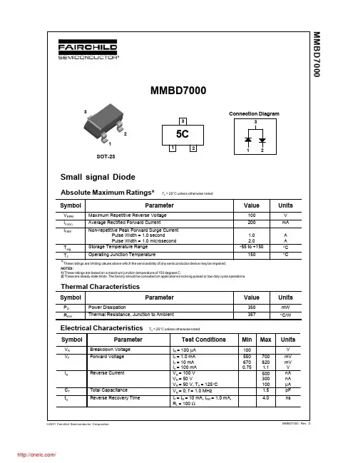

MTMT00A08-1415034-19-1415043-17-1393163-37-1415043-1 8-1393163-3MTMT00A0..MT7874002-2017, Rev. © 2015 Tyco Electronics Corporation,a TE Connectivity Ltd. company Datasheets and product specification according to IEC 61810-1 and to be used only together with the ‘Definitions’ section.Datasheets and product data is subject to the terms of the disclaimer and all chapters of the ‘Definitions’ section, available at /definitionsDatasheets, product data, ‘Definitions’ sec-tion, application notes and all specifications are subject to change.1SCHRACKn Snap-on mounting on DIN-rail n Screw mountingn Pozidrive screws with rising clamp terminals n Logical layout of input-/output connections n White marking areaMT DIN-rail sockets with screw-type terminalsMT 78 750 MT3 DIN-rail socket with screw-type terminals, 11-pin MT 78 755 MT2 DIN-rail socket with screw-type terminals, 8-pinMT78 760 MT3 DIN-rail socket with screw-type terminals, 11-pinMT 78 740 MT3 DIN-rail socket with screw-type terminals, 11-pin MT 78 745 MT2 DIN-rail socket with screw-type terminals, 8-pinGeneral Purpose Relays AccessoriesAccessories Multimode Relay MTZF0235-BF0103-BS0414-AB S0414-ACF0103-BS0311-BB S0414-AAF0200-BS0366-ASocket system MT 78 740 and MT 78 745n 8/11 pin socket for MT2 / MT3n Double A2 screw for simple further connection of coil supplyZ Zb02-2017, Rev. 0217© 2015 Tyco Electronics Corporation, a TE Connectivity Ltd. company Datasheets and product specificationaccording to IEC 61810-1 and to be usedonly together with the ‘Definitions’ section.Datasheets and product data is subject to theterms of the disclaimer and all chapters ofthe ‘Definitions’ section, available at/definitionsDatasheets, product data, ‘Definitions’ sec-tion, application notes and all specificationsare subject to change.2SCHRACKType Part NumberMT 28 800Metal retaining clip MT 8-1393163-0LED and Protection modules for MT 78 740, MT 78 745Type Part NumberMTM T0 0A0Protection diode 1N4007 (A1+, A2-) 7-1393163-6MTM U0 730RC-network 110...230 VAC 7-1393163-8MTM L0 024red LED 24 VAC / VDC 7-1393163-4Function modules for MT 78 740, MT 78 745Type Part NumberMTM Z0 W00 Delay ON 7-1393163-9MTM F0 W00Multifunction 7-1393163-3Technical data - Function modulesNominal voltage 24...240 VDC / VACMains frequency 48...63 HzPrecision of time setting + 0.5 %Readiness for repetition ≤ 0.5 % or 5 msInfluence of temperature ≤ 0.1 %/°CTime range switchable 0.05s...240h in 8 rangesMaterial compliance: EU RoHS/ELV, China RoHS, REACH, Halogen contentrefer to the Product Compliance Support Center at/customersupport/rohssupportcenterAmbient temperature range -25…+55˚CGeneral Purpose RelaysAccessoriesAccessories Multimode Relay MT (Continued)ApprovalsVDE Cert. No. 40009096, cULus E135149Technical data MT78 750/755/760/740/745Rated voltage/Max. switching voltage AC 240/400 VACRated current 10 ADielectric strengthcoil-contact circuit 2500 V rmsopen contact circuit 1500 V rmsadjacent contact circuit 2500 V rmsClearance / creepage coil-contact circuit ≥ 2.8/4 mmMaterial group of insulation parts IIIaInsulation to IEC 60664-1Type of insulation coil-contact circuit basicopen contact circuit functionaladjacent contact circuits basicRated insulation voltage 250 VPollution degree 2Rated voltage system 230/400 VOvervoltage category IIIMaterial compliance: EU RoHS/ELV, China RoHS, REACH, Halogen contentrefer to the Product Compliance Support Center at/customersupport/rohssupportcenterAmbient temperature range -20…+80˚CTerminals screwTerminal screw torque acc. IEC 61984 0.5 Nmmax. 0.7 NmWire strip length 9 mmWire cross sectionsingle wire 2 x 2.5 mm2fine wire 2 x 2.5 mm2with bootlace crimp (DIN 46228/1) 2 x 1.5 mm2Insertion cycles A (10)Max. Insertion Force total 100 NMounting distance ≥ 0 mm, dense packingWeightMT 78 750/760 54 gMT 78 755 47 gMT 78 740 62 gMT 78 745 56 gPackaging unit 25 pcsDIN-rail sockets with screw-type terminalsType Part NumberMT 78 750DIN-rail socket with screw-type 1415035-1terminals, 11-pinMT 78 755DIN-rail socket with screw-type 3-1415035-1terminals, 8-pinMT 78 760DIN-rail socket with screw-type 8-1415034-1terminals, 11-pinMT 78 740DIN-rail socket with screw-type 8-1393163-3terminals, 11-pinMT 78 745DIN-rail socket with screw-type8-1393163-4F0201-BF0203-BF0204-B02-2017, Rev. 0117© 2015 Tyco Electronics Corporation, a TE Connectivity Ltd. company Datasheets and product specificationaccording to IEC 61810-1 and to be usedonly together with the ‘Definitions’ section.Datasheets and product data is subject to theterms of the disclaimer and all chapters ofthe ‘Definitions’ section, available at/definitionsDatasheets, product data, ‘Definitions’ sec-tion, application notes and all specificationsare subject to change.3SCHRACKFunction modules for MT 78 740, MT 78 745FunctionDelay ONDelay OFFsingle shot leading edgesingle shot trailing edgeDelay ONtriggerd by signal contactsingle shotflasher starting with pauseflasher starting with pulseAccessories Multimode Relay MT(Continued)Technical data MT78 602/603/612/613Rated voltage/Max. switching voltage AC 240/400 VACRated current 10 ADielectric strengthcoil-contact circuit 2500 V rmsopen contact circuit 1500 V rmsadjacent contact circuits 2500 V rmsClearance / creepage coil-contact circuit ≥ 2.8/4 mmMaterial group of insulation parts IIIaInsulation to IEC 60664-1Type of insulation coil-contact circuit basicopen contact circuit functionaladjacent contact circuits basicRated insulation voltage 250 VPollution degree 2Rated voltage system 230/400 VOvervoltage category IIIMaterial compliance: EU RoHS/ELV, China RoHS, REACH, Halogen contentrefer to the Product Compliance Support Center at/customersupport/rohssupportcenterAmbient temperature range -40…+70˚CTerminals pcb, solder terminalsInsertion cycles A (10)Max. Insertion Force total 100 NMounting distance ≥ 0 mm, dense packingResistance to soldering heat 270°C/10sWeight 7 gPackaging unit 25 pcsSockets with solder and PCB terminalsType Part NumberMT 78 612Socket 8-pin with solder terminals 7-1415043-1MT 78 613Socket 11-pin with solder terminals 8-1415043-1MT 78 602Socket 8-pin with PCB terminals 9-1415043-1MT 78 603Socket 11-pin with PCB terminals 1415044-1MT 78 613Socket 11-pin with solder terminalsMT 78 603Socket 11-pin with PCB terminalsF0107-AS0309-AAF0104-AS0309-ABF0105-AS0309-ACF0106-AS0309-ADGeneral Purpose RelaysAccessoriesMTMT00A08-1415034-19-1415043-17-1393163-37-1415043-1 8-1393163-3MTMT00A0..MT78740。

Wired expandersAt a glance...EXP-W10•Ten wired zones with 4 outputsEXP-PSU-SM• Ten wired zones with 4 outputs • 1 amp power supply• Capacity for a single 7Ah battery •Contained in a small metal housingEXP-PSU-MM• Ten wired zones with 4 outputs • 2 amp power supply• Capacity for a single 17Ah battery •Contained in a medium metal housingEXP-PSU-LM• Ten wired zones with 4 outputs • 3 amp power supply• Capacity for two 17Ah batteries •Contained in a large metal housingProviding installation flexibility, with ten zones and 4 outputs on board, the expanders give a choice of zone wiring options. These include FSL with various resistor values and 2 wire or 4 wire CC for takeover of legacy systems.A host of installer friendly options are designed to save time on installation and service visits. These include:•Decimal expansion system for more zones per expander. This also makes zone identification easier•Semi-Automatic addressing makes addressing much simpler. No address duplication or lost address links•Device locator to find any expander on the site by simply activating the buzzer inside the expander then walk the site listening for the buzzerA range of wired expanders designed and approved to be used as part of a security grade 2 or 3 system. Bus connected intelligent expanders are intended for use on all i-on control panels.Eaton is a registered trademark of Eaton Corporation.All other trademarks are property of their respective owners.Scantronic product data sheetProduct specificationCompare product compatibility with our easy to read chart: /security-works-withEatonElectrical SectorEMEA Route de la Longeraie 7 1110 Morges, Switzerland Eaton Electrical Products Ltd Security House,Vantage Point Business Village, Mitcheldean, Gloucestershire GL17 0SXTel: +44 (0)1594 545 400Email:***********************Web: 260 m m320 m m239 m m427 m m 160 mm。
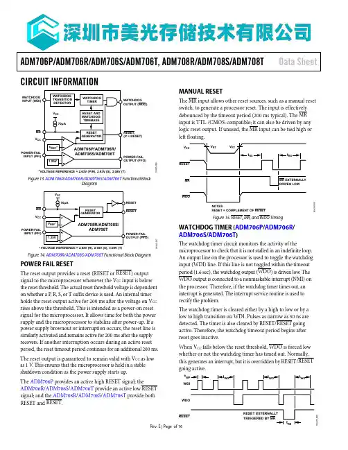
ADM706P/ADM706R/ADM706S/ADM706T, ADM708R/ADM708S/ADM708TData SheetCIRCUIT INFORMATIONWATCHDOG INPUT (WDI)POWER-FAIL INPUT (PFI)POWER-FAIL OUTPUT (PFO)WATCHDOG OUTPUT (WDO)RESET,(P = RESET)*VOLTAGE REFERENCE = 2.63V (P/R), 2.93V (S), 3.08V (T)MR V CC06435-006Figure 13. ADM706P /ADM706R /ADM706S /ADM706T Functional BlockDiagramPOWER-FAIL *VOLTAGE REFERENCE = 2.63V (R), 2.93V (S), 3.08V (T)MR V CC06435-007POWER-FAIL OUTPUT (PFO)Figure 14. ADM708R /ADM708S /ADM708T Functional Block DiagramPOWER FAIL RESETThe reset output provides a reset (RESET or RESET ) output signal to the microprocessor whenever the V CC input is below the reset threshold. The actual reset threshold voltage is dependent on whether a P , R, S, or T suffix device is used. An internal timer holds the reset output active for 200 ms after the voltage on V CC rises above the threshold. This is intended as a power-on reset signal for the microprocessor. It allows time for both the power supply and the microprocessor to stabilize after power-up. If a power supply brownout or interruption occurs, the reset line is similarly activated and remains active for 200 ms after the supply recovers. If another interruption occurs during an active reset period, the reset timeout period continues for an additional 200 ms. The reset output is guaranteed to remain valid with V CC as low as 1 V . This ensures that the microprocessor is held in a stable shutdown condition as the power supply starts up.The ADM706P provides an active high RESET signal; theADM706R /ADM706S /ADM706T provide an active low RESET signal; and the ADM708R /ADM706S /ADM706T provide both RESET and RESET .MANUAL RESETThe MR input allows other reset sources, such as a manual reset switch, to generate a processor reset. The input is effectively debounced by the timeout period (200 ms typical). The MR input is TTL-/CMOS-compatible; it can also be driven by any logic reset output. If unused, the MR input can be tied high or left floating.06435-008NOTESRESET = COMPLEMENT OF RESETFigure 15. RESET , MR , and WDO TimingWATCHDOG TIMER (ADM706P /ADM706R / ADM706S /ADM706T )The watchdog timer circuit monitors the activity of themicroprocessor to check that it is not stalled in an indefinite loop. An output line on the processor is used to toggle the watchdog input (WDI) line. If this line is not toggled within the timeout period (1.6 sec), the watchdog output (WDO ) is driven low. The WDO output is connected to a nonmaskable interrupt (NMI) on the processor. Therefore, if the watchdog timer times out, an interrupt is generated. The interrupt service routine is used to rectify the problem.The watchdog timer is cleared either by a high to low or by a low to high transition on WDI. Pulses as narrow as 50 ns are detected. The timer is also cleared by RESET/RESET going active. Therefore, the watchdog timeout period begins after reset goes inactive.When V CC falls below the reset threshold, WDO is forced low whether or not the watchdog timer has timed out. Normally, this generates an interrupt, but it is overridden by RESET/RESET going active.06435-009Data Sheet ADM706P/ADM706R/ADM706S/ADM706T, ADM708R/ADM708S/ADM708TRev. E | Page of 16OUTLINE DIMENSIONSCOMPLIANT TO JEDEC STANDARDS MS-001CONTROLLING DIMENSIONS ARE IN INCHES; MILLIMETER DIMENSIONS (IN PARENTHESES)ARE ROUNDED-OFF INCH EQUIVALENTS FORREFERENCE ONLY AND ARE NOT APPROPRIATE FOR USE IN DESIGN.CORNER LEADS MAY BE CONFIGURED AS WHOLE OR HALF LEADS.070606-A0.070 (1.78)0.060 (1.52)0.045 (1.14)BSCMAX0.325 (8.26)0.310 (7.87)0.300 (7.62)0.015 (0.38)GAUGE PLANEFigure 24. 8-Lead Plastic Dual In-Line Package [PDIP]Narrow Body(N-8)Dimension shown in inches and (millimeters)CONTROLLING DIMENSIONS ARE IN MILLIMETERS;INCH DIMENSIONS (IN PARENTHESES)ARE ROUNDED-OFF MILLIMETER EQUIVALENTS FOR REFERENCE ONLY AND ARE NOT APPROPRIATE FOR USE IN DESIGN.COMPLIANT TO JEDEC STANDARDS MS-012-AA012407-A0.25(0.0098)0.17(0.0067)1.27(0.0500)0.40(0.0157)0.25(0.0098)0.10(0.0040)COPLANARITY0.10Figure 25. 8-Lead Standard Small Outline Package [SOIC_N]Narrow Body(R-8)Dimensions shown in millimeters and (inches)ADM706P/ADM706R/ADM706S/ADM706T, ADM708R/ADM708S/ADM708TData SheetTABLE OF CONTENTS Array Rev. E | Page of 16Data Sheet ADM706P/ADM706R/ADM706S/ADM706T, ADM708R/ADM708S/ADM708TRev. E | Page of 16ABSOLUTE MAXIMUM RATINGST A = 25°C unless otherwise noted. Table 2.Parameter RatingV CC−0.3 V to +6 VAll Other Inputs −0.3 V to V CC + 0.3 V Input Current V CC 20 mA GND20 mA Digital Output Current20 mA Power Dissipation, N-8 (PDIP) 727 mW θJA Thermal Impedance 135°C/W Power Dissipation, R-8 (SOIC) 470 mW θJA Thermal Impedance 110°C/W Operating Temperature Range Industrial (Version A)−40°C to +85°C Lead Temperature (Soldering, 10 sec) 300°C Vapor Phase (60 sec) 215°C Infrared (15 sec)220°CStorage Temperature Range −65°C to +150°C ESD Rating>4.5 kVStresses at or above those listed under Absolute Maximum Ratings may cause permanent damage to the product. This is a stress rating only; functional operation of the product at these or any other conditions above those indicated in the operational section of this specification is not implied. Operation beyond the maximum operating conditions for extended periods may affect product reliability.ESD CAUTIONADM706P/ADM706R/ADM706S/ADM706T, ADM708R/ADM708S/ADM708T Data Sheet ORDERING GUIDEModel1Temperature Range Package Description Package Option ADM706PANZ −40°C to +85°C 8-Lead Plastic Dual In-Line Package [PDIP] N-8ADM706PARZ −40°C to +85°C 8-Lead Small Outline Package [SOIC_N] R-8ADM706PARZ-REEL −40°C to +85°C 8-Lead Small Outline Package [SOIC_N] R-8ADM706RANZ −40°C to +85°C 8-Lead Plastic Dual In-Line Package [PDIP] N-8ADM706RAR −40°C to +85°C 8-Lead Small Outline Package [SOIC_N] R-8ADM706RARZ −40°C to +85°C 8-Lead Small Outline Package [SOIC_N] R-8ADM706RARZ-REEL −40°C to +85°C 8-Lead Small Outline Package [SOIC_N] R-8ADM706RARZ-REEL7 −40°C to +85°C 8-Lead Small Outline Package [SOIC_N] R-8ADM706SANZ −40°C to +85°C 8-Lead Plastic Dual In-Line Package [PDIP] N-8ADM706SAR −40°C to +85°C 8-Lead Small Outline Package [SOIC_N] R-8ADM706SAR-REEL −40°C to +85°C 8-Lead Small Outline Package [SOIC_N] R-8ADM706SARZ −40°C to +85°C 8-Lead Small Outline Package [SOIC_N] R-8ADM706SARZ-REEL −40°C to +85°C 8-Lead Small Outline Package [SOIC_N] R-8ADM706TANZ −40°C to +85°C 8-Lead Plastic Dual In-Line Package [PDIP] N-8ADM706TAR −40°C to +85°C 8-Lead Small Outline Package [SOIC_N] R-8ADM706TAR-REEL −40°C to +85°C 8-Lead Small Outline Package [SOIC_N] R-8ADM706TARZ −40°C to +85°C 8-Lead Small Outline Package [SOIC_N] R-8ADM706TARZ-REEL −40°C to +85°C 8-Lead Small Outline Package [SOIC_N] R-8ADM708RANZ −40°C to +85°C 8-Lead Plastic Dual In-Line Package [PDIP] N-8ADM708RAR −40°C to +85°C 8-Lead Small Outline Package [SOIC_N] R-8ADM708RAR-REEL −40°C to +85°C 8-Lead Small Outline Package [SOIC_N] R-8ADM708RARZ −40°C to +85°C 8-Lead Small Outline Package [SOIC_N] R-8ADM708RARZ-REEL −40°C to +85°C 8-Lead Small Outline Package [SOIC_N] R-8ADM708SANZ −40°C to +85°C 8-Lead Plastic Dual In-Line Package [PDIP] N-8ADM708SAR −40°C to +85°C 8-Lead Small Outline Package [SOIC_N] R-8ADM708SAR-REEL −40°C to +85°C 8-Lead Small Outline Package [SOIC_N] R-8ADM708SARZ −40°C to +85°C 8-Lead Small Outline Package [SOIC_N] R-8ADM708SARZ-REEL −40°C to +85°C 8-Lead Small Outline Package [SOIC_N] R-8ADM708TANZ −40°C to +85°C 8-Lead Plastic Dual In-Line Package [PDIP] N-8ADM708TAR −40°C to +85°C 8-Lead Small Outline Package [SOIC_N] R-8ADM708TARZ −40°C to +85°C 8-Lead Small Outline Package [SOIC_N] R-8ADM708TARZ-REEL −40°C to +85°C 8-Lead Small Outline Package [SOIC_N] R-81 Z = RoHS Compliant Part.Rev. E | Page of 16。