PMD75变送器按键说明
- 格式:pdf
- 大小:684.89 KB
- 文档页数:8
技术资料 TI 382P/00/en
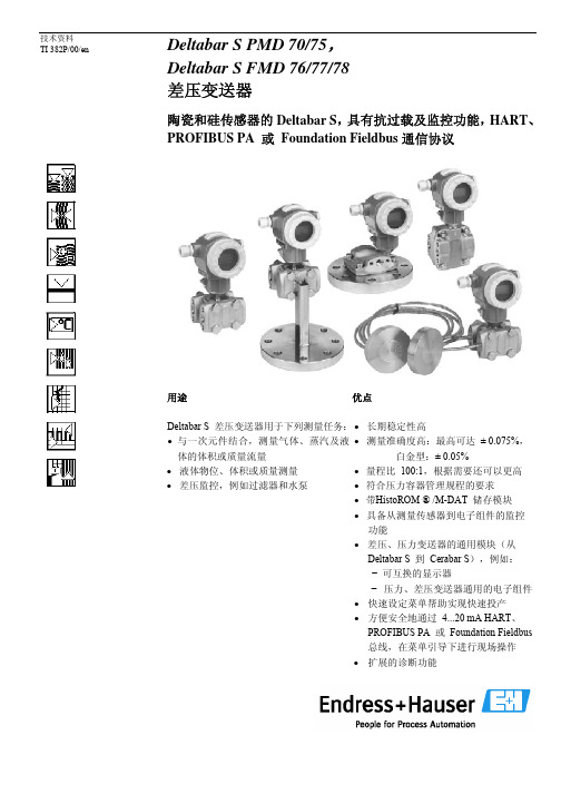
Deltabar S PMD 70/75, Deltabar S FMD 76/77/78 差压变送器
陶瓷和硅传感器的Deltabar S ,具有抗过载及监控功能,HART 、PROFIBUS PA 或 Foundation Fieldbus 通信协议
用途 Deltabar S 差压变送器用于下列测量任务:• 与一次元件结合,测量气体、蒸汽及液体的体积或质量流量
• 液体物位、体积或质量测量
• 差压监控,例如过滤器和水泵
优点
• 长期稳定性高
• 测量准确度高:最高可达 ±
0.075%,白金型:± 0.05% • 量程比 100:1,根据需要还可以更高 • 符合压力容器管理规程的要求 • 带HistoROM ® /M-DAT 储存模块 • 具备从测量传感器到电子组件的监控功能
• 差压、压力变送器的通用模块(从Deltabar S 到 Cerabar S ),例如: − 可互换的显示器
− 压力、差压变送器通用的电子组件• 快速设定菜单帮助实现快速投产 • 方便安全地通过 4...20 mA HART 、PROFIBUS PA 或 Foundation Fieldbus 总线,在菜单引导下进行现场操作 • 扩展的诊断功能
金属测量膜片和膜金属测量膜片和。


Products Solutions ServicesSafety Instructions Deltabar S PMD75, FMD77, FMD784-20 mA HART, PROFIBUS PA,FOUNDATION FieldbusII 1/2 G Ex ia IIC Ga/Gb II 2 G Ex db IIC GbXA00242P-E/00/EN/18.22-00715528762022-04-25Deltabar S PMD75, FMD77, FMD78XA00242P-EDeltabar S PMD75, FMD77, FMD784-20 mA HART, PROFIBUS PA, FOUNDATION FieldbusTable of contentsAbout this document (4)Associated documentation (4)Supplementary documentation (4)General notes: Combined approval (4)Manufacturer's certificates (5)Manufacturer address (5)Other standards (6)Extended order code (6)Safety instructions: General (8)Safety instructions: Special conditions (9)Intrinsic safety (10)Safety instructions: Installation (10)Temperature tables (10)Connection data (11)Flameproof enclosure (13)Safety instructions: Installation (13)Safety instructions: Ex d joints (14)Temperature tables (14)Connection data (15)Endress+Hauser3XA00242P-E Deltabar S PMD75, FMD77, FMD784Endress+HauserAbout thisdocument This document has been translated into several languages. Legally determined is solely the English source text.The document translated into EU languages is available:•In the download area of the Endress+Hauser website: -> Downloads -> Manuals and Datasheets ->Type: Ex Safety Instruction (XA) -> Text Search: …•In the Device Viewer: -> Product tools ->Access device specific information -> Check device featuresIf not yet available, the document can be ordered.Associated documentation This document is an integral part of the following Operating Instructions:HART •BA00270P/00•BA00274P/00PROFIBUS PA •BA00294P/00•BA00296P/00FOUNDATION Fieldbus •BA00301P/00•BA00303P/00Supplementary documentation Explosion-protection brochure: CP00021Z/11The Explosion-protection brochure is available:•In the download area of the Endress+Hauser website: -> Downloads -> Brochures and Catalogs -> Text Search: CP00021Z •On the CD for devices with CD-based documentationGeneral notes:Combined approval The device is suitable for installation with explosion protection "Intrinsic safety Ex ia" or "Flameproof enclosure Ex db".•Before initial commissioning, specify the type of protection.•It is not permitted to change the type of protection after initial commissioning as this can jeopardize the explosion protection.For aluminum enclosures:Void out the explosion protection that is not used on the nameplate.For stainless steel enclosures:Using a striking tool, mark the explosion protection used, or void out the explosion protection that is not used.Deltabar S PMD75, FMD77, FMD78XA00242P-EEndress+Hauser51Depending on the type of protection used: Observe the safetyinstructions for installation with explosion protection "Intrinsicsafety Ex ia" or "Flameproof enclosure Ex db".Manufacturer's certificates EU Declaration of ConformityDeclaration Number:EG05001The EU Declaration of Conformity is available:In the download area of the Endress+Hauser website: -> Downloads -> Declaration -> Type: EU Declaration -> Product Code: ...EU type-examination certificateCertificate number:KEMA 05 ATEX 1009 XList of applied standards: See EU Declaration of Conformity.Manufacturer address Endress+Hauser SE+Co. KGHauptstraße 179689 Maulburg, GermanyAddress of the manufacturing plant: See nameplate.XA00242P-E Deltabar S PMD75, FMD77, FMD786Endress+HauserOther standardsAmong other things, the following standards shall be observed in their current version for proper installation:•IEC/EN 60079-14: "Explosive atmospheres - Part 14: Electrical installations design, selection and erection"•EN 1127-1: "Explosive atmospheres - Explosion prevention and protection - Part 1: Basic concepts and methodology"Extended order codeThe extended order code is indicated on the nameplate, which is affixed to the device in such a way that it is clearly visible. Additional information about the nameplate is provided in the associated Operating Instructions.Structure of the extended order code PMD75,FMD7x –*************+A*B*C*D*E*F*G*..(Device type)(Basic specifications)(Optional specifications)* =Placeholder At this position, an option (number or letter) selected from the specification is displayed instead of the placeholders.Basic specifications The features that are absolutely essential for the device (mandatory features) are specified in the basic specifications. The number of positions depends on the number of features available.The selected option of a feature can consist of several positions.Optional specifications The optional specifications describe additional features for the device (optional features). The number of positions depends on the number of features available. The features have a 2-digit structure to aid identification (e.g. JA). The first digit (ID) stands for the feature group and consists of a number or a letter (e.g. J = Test, Certificate). The second digit constitutes the value that stands for the feature within the group (e.g. A = 3.1 material (wetted parts), inspection certificate).More detailed information about the device is provided in the following tables. These tables describe the individual positions and IDs in the extended order code which are relevant to hazardous locations.Deltabar S PMD75, FMD77, FMD78XA00242P-E Endress+Hauser 7Extended order code: Deltabar S The following specifications reproduce an extract from the product structure and are used to assign:•This documentation to the device (using the extended order code on the nameplate).•The device options cited in the document.Device type PMD75, FMD77, FMD78Basic specificationsXA00242P-E Deltabar S PMD75, FMD77, FMD788Endress+HauserOptional specifications Safety instructions:General•The device is intended to be used in explosive atmospheres as defined in the scope of EN IEC 60079-0 or equivalent national standards. If no potentially explosive atmospheres are present or if additional protective measures have been taken: The device may be operated according to the manufacturer's specifications.•Comply with the installation and safety instructions in the Operating Instructions.•Staff must meet the following conditions for mounting, electrical installation, commissioning and maintenance of the device:•Be suitably qualified for their role and the tasks they perform •Be trained in explosion protection •Be familiar with national regulations •Install the device according to the manufacturer's instructions and national regulations.•Only use the device in media to which the wetted materials have sufficient durability.•Avoid electrostatic charging:•Of plastic surfaces (e.g. enclosure, sensor element, special varnishing, attached additional plates, ..)•Of isolated capacities (e.g. isolated metallic plates)Deltabar S PMD75, FMD77, FMD78XA00242P-E Endress+Hauser 9Safety instructions:Special conditions •In the case of process connections made of polymeric material or with polymeric coatings, avoid electrostatic charging of the plastic surfaces.•For light metal flanges or flange faces (e.g. titanium, zirconium),avoid sparks caused by impact and friction.•To avoid electrostatic charging: Do not rub surfaces with a dry cloth.•In the event of additional or alternative special varnishing on the enclosure or other metal parts or for adhesive plates:•Observe the danger of electrostatic charging and discharge.•Do not install in the vicinity of processes (≤ 0.5 m) generating strong electrostatic charges.XA00242P-E Deltabar S PMD75, FMD77, FMD7810Endress+Hauser Intrinsic safety Explosion protection "Intrinsic safety Ex ia"Safety instructions:InstallationA Zone 1, ElectronicB Zone 0, Process 1Certified associated apparatus 2PMD75, FMD77, FMD78After aligning (rotating) the enclosure, retighten the fixing screw.Intrinsic safety •The intrinsically safe input power circuit of the device is isolated from ground. The dielectric strength is at least 500 V rms .•When the device is connected to certified intrinsically safe circuits of Category Ex ib for Equipment Groups IIC and IIB, the type of protection changes to Ex ib IIC and Ex ib IIB. Do not operate the sensor in Zone 0 if connecting to an intrinsically safe circuit of Category Ex ib.Overvoltage protection Device type PMD75, Basic specification, Position 10 + 11 = M Device type FMD77, FMD78, Basic specification, Position 11 + 12 = M The intrinsically safe input power circuit of the device is isolated from ground. The dielectric strength is at least 290 V rms .Temperature tablesOptional specification, ID Jx = JN Lower limit of the ambient temperature for explosion protection changes to –50 °C.Deltabar S PMD75, FMD77, FMD78XA00242P-E Endress+Hauser 111)Only Device type PMD752)Only Device type PMP75, depending on process connection Do not exceed the max. ambient temperature at the enclosure.Device type PMD75The process temperatures refer to the temperature at the separation membrane.Device type FMD77Deratings between process temperature and ambient temperature at the enclosure depending on the way of installation as well as functional aspects: See Operating Instructions.Device type FMD78The external heat influence depends only on the mountig position of the transmitter itself. Therefore a sufficient capillary length to mount the enclosure at a position with an allowed ambient temperature must be ordered.Connection dataBasic specification, Position 2 = A, B, C, D, E, F 1)Basic specification, Position 2 = A, B, C 2)Basic specification, Position 2 = D, E, FXA00242P-E Deltabar S PMD75, FMD77, FMD78 Basic specification, Position 2 = M, N, O, P, Q, R12Endress+HauserDeltabar S PMD75, FMD77, FMD78XA00242P-E Endress+Hauser 13Flameproof enclosureExplosion protection "Flameproof enclosure Ex db"Safety instructions:InstallationA Zone 1, ElectronicB Zone 1, Process 1Power supply 2PMD75, FMD77, FMD78•After aligning (rotating) the enclosure, retighten the fixing screw.•In potentially explosive atmospheres: Do not open the connection compartment cover and the electronics compartment cover when energized.•Before operation:•Screw in the cover all the way.•Tighten the securing clamp on the cover.•Connect the device:•Using suitable cable and wire entries of protection type "Flameproof Enclosure (Ex db)".•Using piping systems of protection type "Flameproof Enclosure (Ex db)".•When connecting through a conduit entry approved for this purpose,mount the associated sealing unit directly at the enclosure.•For ambient temperatures higher than +70 °C, use suitable heat resisting cables or wires.XA00242P-E Deltabar S PMD75, FMD77, FMD7814Endress+Hauser•Seal unused entry glands with approved sealing plugs that correspond to the type of protection. The plastic transport sealing plug does not meet this requirement and must therefore be replaced during installation.•Only use certified cable entries or sealing plugs. The metal sealing plugs supplied meet this requirement.•Only use genuine spare parts from Endress+Hauser which are specified for the device.Basic specification, Position 3 = B, 2, K Flameproof equipment with G threaded entry holes is not intended for new installations but only for replacement of equipment in existing installations. Application of this equipment shall comply with the local installation requirements.Safety instructions: Ex d jointsIf required or if in doubt: ask manufacturer for specifications.TemperaturetablesOptional specification, ID Jx = JN Lower limit of the ambient temperature for explosion protection changes to –50 °C.Device type PMD75The process temperatures refer to the temperature at the separation membrane.Deltabar S PMD75, FMD77, FMD78XA00242P-E Endress+Hauser 15Device type FMD77, FMD781)Depending on the selected design 2)Depending on the selected version; see Operating Instructions •The specified ambient and process temperature ranges exclusively refer to the explosion protection and must not be exceeded. Operationally permitted ambient temperature ranges can be restricted depending on the version: See Operating Instructions.•Do not exceed the max. ambient temperature at the enclosure.Device type FMD77Deratings between process temperature and ambient temperature at the enclosure depending on the way of installation as well as functional aspects: See Operating Instructions.Device type FMD78The external heat influence depends only on the mountig position of the transmitter itself. Therefore a sufficient capillary length to mount the enclosure at a position with an allowed ambient temperature must be ordered.Connection dataBasic specification, Position 2 = A, B, C, D, E, F Basic specification, Position 2 = M, N, O, P, Q, R*71552876*71552876。

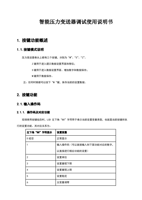
智能压力变送器调试使用说明书1.按键功能概述1.1.按键模式说明压力变送器表头上都有三个按键,分别为“M”、“S”、“Z”。
Z键用于进入提示数据设置界面和移位;S键用于进入数据设置界面、增加数字和数据保存;M键用于数据保存。
注:任何时候都可以按下“M“键,保存当前的设置数据。
2.按键功能2.1.输入操作码2.1.1.操作码及对应功能现场使用按键组态时,LCD左下角“88”字符用于表示当前设置变量类型,也就是当前按键所执注:通过输入各个功能对应的操作码,可以快速进入对应功能。
例如输入“5”,直接进入设置阻尼功能。
例如输入“8”,直接进入设置输出特性。
2.1.2.操作码输入方法图例说明:1.均以当前采集值1 kPa,量程为0~100kPa为例2.2.设置单位2.3.设置量程下限假设原来的量程下限为0,新输入的量程下限为-40kPa。
2.4.设置量程上限2.5.设置阻尼2.6.主变量调零(清零)功能2.7.设置输出特性2.8.零点迁移与量程迁移 [调零和调满]2.9.显示变量设置液晶显示屏能显示“电流”、“百分比”、“主变量”三种变量的一种或交替显示其中的两种(间隔时间4秒)。
在实时正常显示状态,使用S键能更改两个显示变量,当两个显示变量设定为相同的参数,屏幕上固定显示一种变量;当两个显示变量设定为不同的参数时,屏幕上交替显示两种变量。
方法如下:按下“S”键,当前显示变量(如:电流)发生变化,循环显示“电流、百分比、主变量”,当所需要的显示变量(如:主变量)出现在屏幕上时,松开“S”键,即实现了将显示变量“电流”改为“主变量”。
更改显示变量过程中,左下角功能码显示“30”。
例子:假设当前显示变量为“电流”,需要设置为:交替显示“主变量”和“百分比”。
步骤:修改第一个显示变量:按下“S”键,液晶循环显示“电流、百分比、主变量”,当显示“主变量”时,松开“S”键,即可。
此时,液晶交替显示“主变量”和“电流”。
智能压力变送器调试使用说明书1.按键功能概述1.1.按键模式说明压力变送器表头上都有三个按键,分别为“M”、“S”、“Z”。
Z键用于进入提示数据设置界面和移位;S键用于进入数据设置界面、增加数字和数据保存;M键用于数据保存。
注:任何时候都可以按下“M“键,保存当前的设置数据。
2.按键功能2.1.输入操作码2.1.1.操作码及对应功能现场使用按键组态时,LCD左下角“88”字符用于表示当前设置变量类型,也就是当前按键所执行的设置功能。
其对应关系为:左下角“88”字符显示设置变量0或空正常显示1输入操作码(可以直接输入和下面功能对应的数字,以直接进行相应功能的设置)2设置单位3设置量程下限4设置量程上限5设置阻尼6主变量调零7零点迁移与量程迁移 [调零和调满]8输出特性【设置线性输出、或者开方输出】注:通过输入各个功能对应的操作码,可以快速进入对应功能。
例如输入“5”,直接进入设置阻尼功能。
例如输入“8”,直接进入设置输出特性。
2.1.2.操作码输入方法图例说明:1.均以当前采集值1 kPa,量程为0~100kPa为例2.空心显示的数字、字母、符号,表示当前是闪烁显示在实时正常显示状态,按下Z键进入组态数据设置状态。
此时左下角显示“1”。
同时数字区第1个“0”开始闪烁。
按下Z键,依次向右移动闪烁位,直到最后一个“0”开始闪烁。
按下S键,最后一位数字开始从0增加。
这是输入的数字就是操作码,根据输入的操作码不同,将进入不同的功能。
以进入设置主变量单位为例,进行说明:3.等到增加到“2”时,按下“Z”键,此时左下方有一个箭头开始闪烁。
4.此时按下“S”键,则进入“设置单位”菜单,此时左下角显示“2”。
同时下方显示当前的单位。
说明:如果是3按键,则在显示“00002”时,直接按下“M”键,就可以进入“设置单位”。
0 0 0 0 10 0 0 0 1↓00 0 0 10 0 2k P a 0 0 0 0 1如果输入操作码不同,则进入相应的菜单,例如:输入“3”,进入设置量程下限。
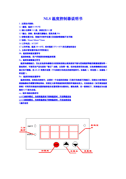
NLS温度控制器说明书1. 主要技术指标:1.1 量程:温度0~99.9℃1.2最小分辨率0.1度,误差正负0.1度1.3 输出:控制:继电器无源输出, 阻性负载30A1.4参数设置方法:轻触开关软件设置(无设置参数接触不良可能)1.5体积:96mm*48mm*72mm1.6工作电压:AC220V1.7工作环境:温度-30~60℃, 相对湿度35%~85%的无腐蚀性场合2、主显示窗设置时显示字符的意义S0:温度控制值设置符号温度控制值:用户所想要的控制温度范围Sc:温度传感器修正符号温度传感器修正:当认定包括传感器在内的控制系统出现误差而不能与更高精度等级的测量装置取得一致结果时,可使用本产品先进的“修正”功能,以取得一致,但勿轻易使用该功能,以免将精确的仪表反修正至不精确。
在-20~20范围内设置一个与误差方向相反的相同值即可。
如偏高3,即设置-3,如偏低3即设置3。
Po: 温度回差值设置符号温度回差值:在纯位式控制中,必须有一个合适的回差值(又称开关差或不灵敏区),回差过小将导致交流接触器动作频繁而降低寿命,回差过大将导致被控制范围的环境波动变大。
在某些场合(如空调室温度控制)可利用回差值的设置使被控值在设置范围内扫描变化,避免浪费。
在一般情况下,回差值定为全量程的0.3%较为合适。
cc:制冷/制热切换符号cc=0为制冷模式,当实际温度高于控制温度时,开启降温设备cc=1为制热模式,当实际温度低于控制温度时,开启加热设备3.操作说明常按功能键3秒进入参数设置菜单,依次设置如下温度控制值设置“SO”,通过设置加和设置减进设置,按功能键完成设温度传感器修正值设置“SC”,通过设置加和设置减进设置,按功能键完成设温度回差值设置“PO”,通过设置加和设置减进设置,按功能键完成设工作模式设置“CC”,通过设置加和设置减进设置,按功能键完成设(“1”热制/“0”制冷)最后显示“----”表示完成全部设置接线图:报警输出5号和6号端子选配一说明:AL代表温度报警下限,AH代表温度报警上限,上限限设置范围为0-99度。
目录1技术参数 (2)2安装说明 (3)3接线说明 (5)3.1 变送器(直流供电型)接线端子说明 (6)3.2 变送器(交流供电型)接线端子说明 (7)3.3 仪器接线功能图 (8)3.4 电极接线示意图 (8)4按键和界面说明 (9)4.1 按键及指示灯说明 (9)4.2 界面说明 (10)5操作说明 (13)5.1 参数设置操作 (14)5.2 校正操作 (15)6电极诊断及出错信息 (17)7电极保养说明 (19)8操作密码 (20)8.1 参数设置密码 (20)8.2 校正密码 (20)附1缓冲液 (21)附2技术术语 (23)安全预防措施请认真阅读并遵守下列要求!在仪器上电前,请对照您持有仪表的型号,确认供电电压:变送器需用18V-30VDC直流电源供电变送器需用100V-250V AC交流电源供电打开仪器会有电路部分暴露,因此除了接线仓和仪表透明罩外,不应打开仪器其它部分。
打开的仪器内部能接触到的器件上的电压足以威胁人的生命。
若需检修,需要返回厂家。
只有厂家专业人员才能在带电情况下打开仪器。
当相应的保护失效时,请停止操作。
出现以下情况时,保护可能失效:◇仪器外观有明显破损◇仪器不能正常测量◇长期储存于超过70℃的环境中◇经过剧烈的震动或碰撞后11 技术参数22安装说明①31、请选择合适位置安装pH计(以下简称仪器),避免仪器直接受到阳光照射。
2、安装前请阅读本说明书,以免接线不正确导致仪器损坏。
3、pH或ORP电极信号传输须采用专用电极电缆,请不要用一般电缆代替,否则将产生错误的测量结果。
4、仪器内部的继电器为小电流继电器,若要控制较大动力的图2-1 仪器和动力装置接线示意图43 接线说明接线仓内部图(拆掉压线盖)接线步骤:打开接线仓盖→拆下压线盖→接线→装上压线盖→装上接线仓盖。
5673.3 仪器接线功能图84 按键和界面说明Wash 灯:清洗指示灯,当清洗继电器动作时,此灯亮Alarm灯:报警指示灯,仪表超限报警或自检报警时,此灯亮94.2 界面说明4.2.1 测量界面入码自动清零,请操作人员重新输入。
Detlabar S FMD76/77/78, PMD70/75 差压变送器操作手册目录1、安全手册 (3)1.1 设计用途 (3)1.2 安装、调试和操作 (3)1.3 操作安全性 (3)1.4 安全惯例和图标的注释 (4)2、认证 (4)2.1 仪表设计 (4)2.2 供货范围 (5)2.3 CE标志 (6)2.4 注册商标 (6)3、安装 (6)3.1 接收和存储仪表 (6)3.2 安装条件 (7)3.3 安装手册 (7)3.4 安装后的检查 (12)4.接线 (12)4.1 仪表的接线 (12)4.2 电子腔室的接线 (13)4.3 等电势 (15)4.4 接线后检查 (15)5.操作 (16)5.1 现场显示模块(可选) (16)5.2 操作按钮 (17)5.3 现场操作-不带就地现场显示 (19)5.4 现场操作-带现场显示 (22)5.6 TOF TOOL操作程序 (25)5.7 通过HART手持终端操作 (25)5.8 Commuwin II操作程序 (25)5.9 锁定/解锁操作 (26)5.10 工厂设定(重置) (27)6 调试 (28)6.1 功能检测 (28)6.2 语言选择与测量模式选择 (28)6.3 位置调节 (29)6.5 液位模式 (32)6.6 差压测量 (36)7 维护 (39)7.1 表面清洁 (39)8.故障排除 (39)8.1 错误信息 (39)8.2 输出响应错误 (45)8.3 确认错误信息 (46)8.4 维修 (46)8.5 带防爆认证的仪表维修 (46)8.6 备件 (47)8.7 返修仪表 (47)8.8 存储 (48)8.9 软件 (48)9.技术数据 (49)10 附件 (49)10.1现场显示,TOF TOOL和现场手操器的操作菜单 (49)10.2 HART Commuwin II操作矩阵 (49)索引1、安全手册1.1 设计用途Detlabar S 是测量差压、流量和液位的差压变送器。
佰特变送器按键操作方法
佰特变送器按键操作方法如下:
1. 按下电源开关,启动变送器;
2. 使用向上和向下箭头键调整频道;
3. 使用左右箭头键调整音量;
4. 按下确认键以确定所选的频道和音量设置;
5. 按下静音键可将音量静音;
6. 按下菜单键可进入设置菜单进行更多高级设置;
7. 按下退出键可退出设置菜单或返回上一级菜单。
根据不同型号的佰特变送器,按键操作方法可能会有些许区别,建议在使用前查阅相关的使用说明书以获取更详细的操作指南。
简明操作指南Deltabar SPMD70, PMD75, FMD76, FMD77, FMD78差压测量本文档为《简明操作指南》。
详细信息请参考随箱CD光盘中的《操作手册》和其他文档资料。
《简明操作指南》不得替代随箱包装中的《操作手册》。
整套设备文档包括:•《简明操作指南》•CD光盘,内含《操作手册》KA01018P/00/ZH/14.1371218527目录Deltabar S PMD70, PMD75, FMD76, FMD77, FMD78 4...20 mA HART2Endress+Hauser目录1 安全指南 . . . . . . . . . . . . . . . . . . . . . . . . . . . . . . . . . . . . . . . . . . . . . . . . . . . . . . 31.1 指定用途 . . . . . . . . . . . . . . . . . . . . . . . . . . . . . . . . . . . . . . . . . . . . . . . . . . . . . . . . . . . . . . . . . . . . . . . . . . . . . . 31.2 安装、调试和操作 . . . . . . . . . . . . . . . . . . . . . . . . . . . . . . . . . . . . . . . . . . . . . . . . . . . . . . . . . . . . . . . . . . . . . . 31.3 操作安全和过程安全 . . . . . . . . . . . . . . . . . . . . . . . . . . . . . . . . . . . . . . . . . . . . . . . . . . . . . . . . . . . . . . . . . . . . 31.4 返回 . . . . . . . . . . . . . . . . . . . . . . . . . . . . . . . . . . . . . . . . . . . . . . . . . . . . . . . . . . . . . . . . . . . . . . . . . . . . . . . . . . 41.5安全图标 . . . . . . . . . . . . . . . . . . . . . . . . . . . . . . . . . . . . . . . . . . . . . . . . . . . . . . . . . . . . . . . . . . . . . . . . . . . . . . 42 安装 . . . . . . . . . . . . . . . . . . . . . . . . . . . . . . . . . . . . . . . . . . . . . . . . . . . . . . . . . . 42.1 常规安装指南 . . . . . . . . . . . . . . . . . . . . . . . . . . . . . . . . . . . . . . . . . . . . . . . . . . . . . . . . . . . . . . . . . . . . . . . . . . 42.2 安装位置 . . . . . . . . . . . . . . . . . . . . . . . . . . . . . . . . . . . . . . . . . . . . . . . . . . . . . . . . . . . . . . . . . . . . . . . . . . . . . . 52.3 带隔膜密封系统的仪表的安装指南- FMD78 . . . . . . . . . . . . . . . . . . . . . . . . . . . . . . . . . . . . . . . . . . . . . . . . . 62.4组装和安装“分离型外壳”型仪表 . . . . . . . . . . . . . . . . . . . . . . . . . . . . . . . . . . . . . . . . . . . . . . . . . . . . . . . . . 83 接线 . . . . . . . . . . . . . . . . . . . . . . . . . . . . . . . . . . . . . . . . . . . . . . . . . . . . . . . . . . 93.1 连接设备 . . . . . . . . . . . . . . . . . . . . . . . . . . . . . . . . . . . . . . . . . . . . . . . . . . . . . . . . . . . . . . . . . . . . . . . . . . . . . . 93.2 连接测量单元 . . . . . . . . . . . . . . . . . . . . . . . . . . . . . . . . . . . . . . . . . . . . . . . . . . . . . . . . . . . . . . . . . . . . . . . . . 104 操作 . . . . . . . . . . . . . . . . . . . . . . . . . . . . . . . . . . . . . . . . . . . . . . . . . . . . . . . . . 124.1 现场显示单元(可选) . . . . . . . . . . . . . . . . . . . . . . . . . . . . . . . . . . . . . . . . . . . . . . . . . . . . . . . . . . . . . . . . . . 124.2 操作单元 . . . . . . . . . . . . . . . . . . . . . . . . . . . . . . . . . . . . . . . . . . . . . . . . . . . . . . . . . . . . . . . . . . . . . . . . . . . . . 144.3 通过现场显示单元进行现场操作 . . . . . . . . . . . . . . . . . . . . . . . . . . . . . . . . . . . . . . . . . . . . . . . . . . . . . . . . . 174.4锁定/解锁操作 . . . . . . . . . . . . . . . . . . . . . . . . . . . . . . . . . . . . . . . . . . . . . . . . . . . . . . . . . . . . . . . . . . . . . . . 215 调试 . . . . . . . . . . . . . . . . . . . . . . . . . . . . . . . . . . . . . . . . . . . . . . . . . . . . . . . . . 225.1 位置调整 . . . . . . . . . . . . . . . . . . . . . . . . . . . . . . . . . . . . . . . . . . . . . . . . . . . . . . . . . . . . . . . . . . . . . . . . . . . . . 235.2 差压测量 . . . . . . . . . . . . . . . . . . . . . . . . . . . . . . . . . . . . . . . . . . . . . . . . . . . . . . . . . . . . . . . . . . . . . . . . . . . . . 245.3 液位测量 . . . . . . . . . . . . . . . . . . . . . . . . . . . . . . . . . . . . . . . . . . . . . . . . . . . . . . . . . . . . . . . . . . . . . . . . . . . . . 265.4流量测量 . . . . . . . . . . . . . . . . . . . . . . . . . . . . . . . . . . . . . . . . . . . . . . . . . . . . . . . . . . . . . . . . . . . . . . . . . . . . . 29Deltabar S PMD70, PMD75, FMD76, FMD77, FMD78 4...20 mA HART安全指南1安全指南1.1指定用途Deltabar S是差压变送器,用于差压、液位和流量测量。