057tgp_green_ business
- 格式:pot
- 大小:327.00 KB
- 文档页数:10

EPSON RC+ 7.0选件Force Guide 7.0 SPEL+ Language Reference Rev.5EPSON RC+ 7.0选件Force Guide 7.0SPEL+ Language ReferenceRev.5Copyright © 2015-2018 SEIKO EPSON CORPORATION. All rights reserved.Force Guide 7.0 SPEL+ Language Reference Rev.5 i前言感谢您购买本公司的机器人系统。
本手册记载了正确使用Force Guide 7.0所需的事项。
使用该软件时请仔细阅读本手册与其他相关手册。
阅读之后请妥善保管,以便随时取阅。
保修本机器人及其选装部件是经过本公司严格的质量控制、测试和检查,并在确认性能满足本公司标准之后出厂交付的。
在交付产品的保修期内,本公司仅对正常使用时发生的故障进行免费修理。
(有关保修期事项,请咨询您的区域销售办事处。
)但在以下情况下,将对客户收取修理费用(即使在保修期内):1.因不同于手册内容的错误使用以及使用不当而导致的损坏或故障。
2.客户未经授权进行拆卸导致的故障。
3.因调整不当或未经授权进行修理而导致的损坏。
4.因地震、洪水等自然灾害导致的损坏。
警告、小心、使用:1.如果机器人或相关设备的使用超出本手册所述的使用条件及产品规格,将导致保修无效。
2.本公司对因未遵守本手册记载的“警告”与“注意”而导致的任何故障或事故,甚至是人身伤害或死亡,均不承担任何责任,敬请谅解。
3.本公司不可能预见所有可能的危险与后果。
因此,本手册不能警告用户所有可能的危险。
ii Force Guide 7.0 SPEL+ Language Reference Rev.5商标Microsoft、Windows、Windows标识、Visual Basic及Visual C++为美国MicrosoftCorporation在美国和/或其它国家的注册商标或商标。

名词词法过关练习(一)一、把单数变成复数•coat _______ skirt _______•dress _______ house _______•watch _______ car _______•brush _______ box _______•toy _______ umbrella _______•ticket _______ cloakroom _______ •teacher _______ son _______•student _______ job _______•operator _______ fly _______二、请写出下列名词复数加s后的读音:pens [ ] ducks [ ]dogs [ ] chicks [ ]bears [ ] rabbits [ ]cards [ ] flowers [ ]buses [ ] boxes [ ]watches [ ] brushes [ ]三、写出下列名词的复数并写出所加s或es的音标。
glass —— [ ]match —— [ ]wish —— [ ]baby ——[ ]butterfly — [ ]boy — [ ]toy — [ ]名词词法过关练习(二)一、写出下列名词的复数形式1、orange2、class3、text4、monkey5、piano6、child7、shelf 8、bed 9、country10、family 11、toy 12、foot13、Japanese 14、radio 15、photo16、army 17、tomato 18、fox19、woman 20、knife 22、sheep二、用所给名词的适当形式填空。
1. We are ________ (student).2. I have five ________ (watch).3. Her father is a ________ (doctor).4. What’s your ______ (job)?5. What are their ________ (job)?6. These _________ (shelf) are not very good.7. Two ________ (wolf) are in the forest.8. The ____________ (housewife) are very lazy.9. I have two ________ (knife). Do you needone?10. There is a _______ (hero).11. This _______ (potato) is very nice.12. There is a red _________ (tomato) on thetable.13. We have four ________ (piano) in ourschool.三、选择填空( ) 1. The _____ are on the table.A. knifeB. knifesC.knives( ) 2. We need three more _____ to cookchips.A. potatoB. potatosC. potatoes( ) 3. What big _____ the tiger has!A. toothB. toothesC. teeth( ) 4. Please remember to give the horsesome______.A. leafsB. leavesC. leaf( ) 5. There are 34 _____ in our school.A. woman teachersB. women teachersC. women teacherD. womans teachers( ) 6、There on the wall .They are verybeautiful.A. are photoesB. are photosC. is a photoD. is photos( )7. There are four and two inthe group.A. Japanese, Germen B Japaneses, GermenC. Japanese,German C.Japanese, Germans( )8. That’s art book.A. anB. aC. the D are( )9. There some in the river.A. is ,fishB. are, fishsC. is, fishsD. are ,fish( )10. There two in the box.A. is watchB. are watchesC. are watchD. iswatches( )11. We should clean twice a day.A .our tooth B.we tooths C. us teethD.our teeth( )12. In Britain _____ are all painted red.A.letter boxesB.letters boxesC.letter boxD.letters box四、写出下列句子的复数句子。
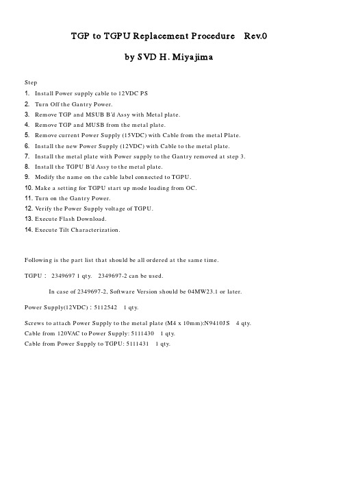
TGP to TGPU Replacement Procedure Rev.0by SVD H. MiyajimaStep1. Install Power supply cable to 12VDC PS2. Turn Off the Gantry Power.3. Remove TGP and MSUB B’d Assy with Metal plate.4. Remove TGP and MUSB from the metal plate.5. Remove current Power Supply (15VDC) with Cable from the metal Plate.6. Install the new Power Supply (12VDC) with Cable to the metal plate.7. Install the metal plate with Power supply to the Gantry removed at step 3.8. Install the TGPU B’d Assy to the metal plate.9. Modify the name on the cable label connected to TGPU.10. Make a setting for TGPU start up mode loading from OC.11. Turn on the Gantry Power.12. Verify the Power Supply voltage of TGPU.13. Execute Flash Download.14. Execute Tilt Characterization.Following is the part list that should be all ordered at the same time.TGPU:2349697 1 qty.2349697-2 can be used.In case of 2349697-2, Software Version should be 04MW23.1 or later.Power Supply(12VDC):5112542 1 qty.Screws to attach Power Supply to the metal plate (M4 x 10mm):N9410JS 4 qty. Cable from 120VAC to Power Supply: 5111430 1 qty.Cable from Power Supply to TGPU: 5111431 1 qty.Detailed Procedure.1. Install Power supply cable to 12VDC PSDue to the change of connector style, new cable should be used and connected. Two cables are used.One is for 120VAC input connection (5111430). Refer to the following picture.BRN (Brown) is connected to L and LBLU (Light Blue) is connected to N.And another cable is used to supply 3 kinds of DC outputs to TGPU from Power Supply (5111431).See the following picture.Following is the connection at TGPU Power Supply side:RED (Red): +24V, GRY (Gray): RTN (Photo left side connector)ORN (Orange): +12V, WIT (White): RTN, BLU (Blue): -12V (Photo center side connector)YEL (Yellow): +5V, BLK (Black): RTN (Photo right side connector)2. Turn Off the Gantry Power.3. Remove TGP and MSUB B’d Assy with Metal plate.Power Off4. Remove TGP and MUSB from the metal plate.5.Remove current Power Supply (15VDC) with Cable from the metal Plate.6. Install the new Power Supply (12VDC) with Cable to the metal plate.7. Install the metal plate with Power supply to the Gantry removed at step 3.1, Disconnect theconnector from thebottom of TGP metalplate.2, Remove the screw.3, Remove the screw.Note: The metal plate can be removed by removing the screw,need to support the metal plate with your hand.1, Remove these screws.2, Remove the connector (* in step 4 picture)with flat screwdriver.And the current Power Supply can beremoved.1, Install new Power Supply with 4 screws. (Seered color circle in left picture).(Green colored circle is old PS screw holes).The screws should be new ones since thesescrews are metric. Original ones are inch.2, Install connector in (*) step4 to the metalplate.2, Install screws.1, Install screws.8. Install the TGPU B’d Assy to the metal plate.(1) Fix TGPU to the metal plate.(2) Connect all connectors that were removed in previous step.See next step.9. Modify the name on the cable label connected to TGPU.10. Make a setting for TGPU start up mode loading from OC.Open shell and type the following commands: % cd /usr/g/fw % touch tgpFtpClose shell after confirmation that tgpFtp file exists in the directory.11. Turn on the Gantry Power.See step 2.12. Verify the Power Supply voltage of TGPU.Specifications:… 5.0~5.1V … 11.8V~12.2V … -11.8V~-12.2V24V … 23.8V~24.2V The checkpoints are shown in step9 (*2).Also refer to the left Illustration. Adjust +12/-12 as balanced to center pointsince both of them uses one trimmer. See the following Illustration for adj. pots.13. Execute Flash Download. 14. Execute Tilt Characterization.Calibration -> Mechanical Characterization -> Tilt Characterization Finished.。


12/30/1999OPERATOR’S MANUALADDENDUMModel:GP1650/1850 Series Subject:New FISHING MODE andFeature EnhancementsThis Furuno GP1650/1850 Series Plotter has a newly developed software revision that includes many exciting new features. This addendum is a supplement to your Operator’s Manual. It describes these new features and explains how to utilize them.TABLE OF CONTENTSA. Explanation of New Features (2)B. Operator’s Manual Information (3)C. Software Revision Check (3)D. New Fishing Modes and Mark Function (5)E. New Memory Card Storage Function (8)F. Navionics “Nav-Chart” Cartography “OFFSET” Capability (11)G. RTCM DGPS Data Output(1650/1850 “D”/”DF” ONLY) (12)H. New “Wide-Screen” E/S Mode(1650/1850 “F”/”DF” ONLY)..13A.Explanation of New Features:1.New "Fishing Plotter Mode": This feature allows you to place yourGP1650/1850 in either a "Pleasure Mode" or a "Fishing Mode". Inthe "Pleasure Mode", the GP1650/1850 operates the same asprevious software revisions.In the new Fishing Mode, you can place Marks and Line Points (UpTo 5000) in internal memory. The mode also allows you to changeTrack Colors, Start/Stop Own Ship Tracking, and Edit Mark Entrieseasily from a newly added Softkey Menu. In “Pleasure Mode”, thisnew Softkey Menu is not displayed.2. New "Memory Card Storage" Capability: It is now possible tostore Marks/Lines, Waypoints/Routes, Tracks, and ConfigurationInformation (Menu Settings) of the GP1650/1850 Series onto amemory card. The entire memory contents of a GP1650/1850 can bestored into a single memory card for storage or cloning yourGP1650/1850. This provision allows Unlimited Data Storage for theGP1650/1850 Series. Uploading/Downloading Waypointinformation via the RS232 PC Interface has remained unchanged.The part number for the RAM Storage Card is 000-140-483. It isavailable from any authorized Furuno Dealer.3.RTCM DGPS Data Output: It is now possible to send RTCM 104,Differential Correction Data, to other Differential-Ready GPSProducts on your vessel. This feature requires a "D" or ”DF” version.4.Navionics Cartography "OFFSET" Capability: This newsoftware allows operators to OFFSET Navionics Charts. Previoussoftware versions did not have this capability.5."Wide-Screen" Echo Sounder Mode: When operating in the “SplitScreen” mode (Plotter and Sounder display), this function allows theuser to select between the wide (50%) or narrow (25%) sounderscreen. This feature requires a “F” or “DF” version.B.Operator’s Manual – The Operator’s Manual included with yourGP1650/1850 is not updated at this time. We will offer revisedOperator’s Manuals late in the first quarter of 2000.Please call your authorized Furuno Dealer for further information.This software revision does not effect the Installation Manual included with your GP1650/1850.C.Software Revision Check (For Confirmation Only) - TheSoftware Revision of your GP1650/1850 can be found by using the “Self Test” procedure on page 4.The “Memory I/O” test will display the software revision number in the upper left corner of the display.The last two digits of the number indicate which software version is currently installed.If your revision number is lower than the ones listed below, a simplesoftware upgrade for any GP1650/1850 is all that is necessary to takeadvantage of the new features available.Call your local Furuno Dealership for more information.-GP1650/GP1650D Software Version 145-1801-013 and higher -GP1650F/GP1650DF Software Version 145-1802-011 and higher -GP1850D Software Version 145-1826-006 and higher -GP1850DF Software Version 145-1827-006 and higherD iagnostic TestsMemory, I/O port testThis test conducts a general check of the dis-play unit and the antenna unit. The unit dis-plays the results for each device or component checked as OK or NG (No Good).1.Press the [MENU] key to open the mainmenu.2.Press the soft key CONFIGURATION toshow the configuration menu.Figure 12-1 Configuration menu3.Press the soft key SYSTEM MENU toopen the system menu.Figure 12-2 System menu 4.Press the soft key SELF TEST to openthe test menu.Figure 12-3 Test menu5.Press the soft key MEMORY•I/O TESTto start the test. Test results and program nos. are shown as below.NOTE: Special connections are required to check PORT1 and PORT2 otherwise, "--" appears.Figure 12-4 Memory, I/O test results 6.The test runs continuously. To return tothe self test menu, press the soft key RETURN.Note: BEACON RECEIVER results only ap-pear on GP-1650/1850 "D" and "DF" Ver.C hanging Operation ModeOperation mode can be changed between PLEASURE and FISHING. FISHING mode provides mark/line entr ies on the PLOTTER display. Up to 5000 Marks can be entered together with track points. Apportioning between track and mark memory can be changed by menu. Pressing the [HIDE/SHOW] key changes the function of soft keys.Holding tracks, changing track color, select-ing mark colors, and the type of marks/lines can be performed by the soft keys directly.1.Press the [MENU] key and the soft key DISPLAY OPTIONS. The display setup1menu appears.Display setup1 menu2.Press w to select OPERATION MODE.3.Press the soft key EDIT to show the OP-ERATION MODE window.OPERATION MODE window 4.Press v or w to select PLEASURE or FISHING.5.Press the soft key ENTER or the [ENTER]key to finish.In the FISHING mode, pressing the [HIDE/SHOW] key changes the function of soft keys as follows.MARK S1 Entering MarksSelect the Fishing Mode to enable entry of marks on the PLOTTER display. Select the location desired with the cursor, or turn off the cursor to enter the mark at own ship po-sition. Press ing the [HIDE/SHOW] key changes the function of soft keys. Press the soft key MARK ENTRY to enter a new mark. The mark is entered in the shape and color selected from the MARK SHAPE and MARK COLOR selection windows.2 Changing Mark AttributesYou can select the shape s, line types and color s of Marks and L ine s on the TRACK display.1.Press the [HIDE/SHOW] key to show thesoft key MARK EDIT.2.Press the soft key MARK EDIT to showthe MARK/LINE window.MARK SHAPEMARK LINEMARK COLOR YELLOW.MA RK/LINE window3.Press the soft key MARK SHAPE tochange mark shape, the soft key MARKLINE to change mark line, or the soft keyMARK COLOR to change mark color.Mark shapePress the soft key MARK SHAPE to dis-play the MARK SHAPE window. Press vor w to select mark shape desired.MARK SHAPE windowMark linePress the soft key MARK LINE to display the MARK LINE window. Press v or w to select mark line desired.MARK LINE windowMark colorPress the soft key MARK COLOR to dis-play the MARK COLOR window. Press v or w to select mark color desired.MARK COLORv™™™™™™w' REDYELLOWGREENLIGHT BLUEPURPLEBLUEWHITEMARK COLOR window4.Press the soft key ENTER or the [ENTER]key.5.Press the soft key RETURN to finish. Marks/lines entered hereafter are inscribed in the shape, color and line type selected here.3 Changing Mark SizeMark size can be selected from STD (stan-dard) and SMALL.1.Press the [MENU] key to display the mainmenu.2.Press the soft key CHART SETUP OP-TIONS.3.Press the soft key CHART DETAIL toopen the CHART DETAIL menu.CHART DETAIL menu4.Press w to select MARK SIZE.5Press the soft key EDIT.6.Press v or w to select STD (standard) orSMALL.7.Press the [ENTER] key.4 Erasing MarksErasing individual marks/lines1.Operate the cursor pad to place the cur-sor on the mark you want to erase.2.Press the [CLEAR] key. The mark se-lected is erased.Note: To erase a line, place the cursoron the e d ge of the line. The line segment will be erased.Erasing whole marks/linesYou can erase all marks and lines. Be abso-lutely sure you want to erase all marks and lines; erased marks and lines cannot be re-stored.1.Press the [MENU] key followed by the softkeys CHART SETUP OPTIONS andTRACK CONTROL.2.Press the soft key ERASE MARK. Youare asked if you are sure to erase allmarks and lines.3.Press the [ENTER] key to erase, or pressthe [CLEAR] key to escape.5 Displaying Track andMark PointsNumber of track and mark points used ap-pears in the TRACK STATUS window on the TRACK CONTROL display. For further de-tails see TRACK CONTROL WINDOW.SAVING AND LOADING DATA TO/FROM MEMORY CARDSThe following data can be saved to memory card:• Mark/line• Waypoints/routes• Track• Configration (menu settings)1 Formatting Memory CardsBefore you can use a memory card it must be formatted. Note that formatting always erases all saved data on the card!1.Insert the memory card you want to for-mat into the slot.2.Press the [MENU] key followed by the softkeys CONFIGRATION and UPLOAD/ DOWNLOAD DATA.SAVE DATA display3.Press the soft key SAVE DATA TOMEMORY CARD and the soft key FOR-MAT. You are asked if you are ready to format the memory card.4.Press the [ENTER] key to format (or pressthe [CLEAR] key to escape). Now FOR-MATTING MEMORY CARD appears. Do not remove the card while it is being for-matting. When the formatting is com-pleted, FORMAT COMPLETED appears.5.Press the [ENTER] key to finish. Now youcan record data to the memory card.2 Saving Data to MemoryCardThe memory card can save four items of data; track, mark/line, waypoint/route and configu-ration.Saving data1.Insert a formatted memory card into theslot.2.Press the [MENU] key followed by the softkeys CONFIGURATION and UPLOAD/ DOWNLOAD DATA.3.Press the soft key labeled SAVE DATATO MEMORY CARD. The SAVE DATA display appears.4.Press v or w to select item to save.5.Press the soft key EDIT to open theTRACK, MARK/LINE, WAYPOINTS/ ROUTES or CONFIGRATION window.6.Press v to select ON.7.Press the soft key ENTER or the [ENTER]key.8.Repeat from steps 4 to 7 to save otherdata if desired.9.Press the soft key SAVE DATA. The fol-lowing message appears and saving starts. Do not remove the memory card while data is being saved.NOW SAVING DATA TOMEMORY CARD. DO NOTTURN OFF THE POWER UNTILSAVING COMPLETED.SAVE DATA messageWhen saving is completed, COM-PLETE SAVING DATA appears.Error messageMemory card not insertedPress the [ENTER] key to return to the SAVE DATA display.MEMORY CARD NOTINSERTED. INSERT CARDPRESS "ENTER" keyTO CONTINUE.NOT INSERTED message Unformatted memory cardPress the [ENTER] key to return to the SAVE DATA display. And format it refering to the previous page.MEMORY CARD NOTFORMATTEDPRESS "ENTER" keyTO CONTINUE.NOT FORMATTED messageWrong card insertedAppears when a chart card is inserted. Press the [ENTER] key to return to the SAVE DATA display. Replace it with a formatted memory card.WRONG CARD INSERTED.INSERT MEMORY CARD.PRESS "ENTER" keyTO CONTINUE.WRONG CARD messageData overwriteData type to be recorded exists on memory card. (Two or more of same data type can-not be recorded.) Press the [ENTER] key to overwrite same data type on the card, or press the [CLEAR] key to escape.OVERWRITE message3 Loading Data fromMemory CardData (track, marks, waypoints, configuration) can be loaded from a memory card and dis-played on the screen. This feature is useful for observing past data and setting up the equipment for a specific purpose (with “con-figuration”).1.Press the [MENU] key followed by the softkeys CONFIGURATION and UPLOAD/ DOWNLOAD DATA.2.Press the soft key LOAD DATA FROMMEMORY CARD to show the LOAD DATA display.LOAD DATA display3.Press v or w to select item to load.4.Press the soft key EDIT to show theON/OFF selection window.5.Press v to select ON. Press the soft keyENTER or the [ENTER] key. If the memory card does not contain the item selected, the buzzer sounds and ON can-not be selected.6.After you select all items desired, pressthe soft key LOAD DATA to load data. Thefollowing message appears.NOW LOADING DATA FROMMEMORY CARD. DO NOTTURN OFF THE POWER UNTILLOADING COMPLETE.LOAD DATA messageAfter loading is completed, the followingmessage appears.COMPLETE LOADING DATA.PRESS "ENTER" KEYTO CONTINUE.COMPLETE message7.Press the [ENTER] key.Note on loading dataTrackSince loaded track data is added to internaltrack, oldest track will be e rased when thetrack memory capacity is exceeded.Waypoint/routeThe loaded data OVERWRITES previouslystored waypoints and routes. BE CAREFUL NOT TO DESTROY VALUABLE DATA! Mark/lineThe loaded data is added to internal data.When the mark/line memory becomes full nomarks may be entered.ConfigurationThe loaded data replaces current configura-tion settings. Press the [ENTER] key to re-start. If the memory card is ejected whileloading or data could not be loaded, pressthe [ENTER] key to restart with default set-tings. Note that track memory capacity is notsaved or loaded.This section describes the various options which allow you to set up your unit to suit your needs.1CHART SETUP OPTIONSmenuThe chart offset options menu provides three menus: chart offset, track control, and chart detail.1.Press the [MENU] key to open the main menu.2.Press the soft key CHART SETUP OP-TIONS.11-1 Chart setup options menuCUSTOMIZING YOUR UNITCHART OFFSET -NEW FOR NAVIONICSIn some instances position may be off by a few minutes. For example, the position of the ship is shown to be at sea while it is in fact moored at a pier. You can compensate for this error by offsetting chart position as fol-lows:1.Press the [MENU] key followed by the soft keys CHART SETUP OPTIONS and CHART OFFSET.Plotter display,chart offset selectede the cursor pad to place the cursor where to offset chart position.3.Press the soft key SET OFFSET.4.Press the soft key RETURN to finish.To cancel chart offset, press the soft key RE-SET OFFSET at step 3 in the above proce-dure.TRACK CONTROL menuThis menu mainly controls track color and track plotting interval. For further details see Track Chapter.SETUP NMEA/DGPS PORT 2 menu descriptionThis menu should be set according to the specifications of the equipment connected to connectors PORT 1 (NMEA) and PORT 2 (DGPS) at the rear of the display unit. The menu can be displayed by pressing the [MENU] key followed by the soft keys CON-FIGURATION and SETUP NMEA PORT 2. For detailed information, see the installation manual.FORMAT- WITH NEW RTCM(OUTPUT) Selects data format of connected equipment; NMEA0183 version 1.5, version 2.0, RTVM104 (EXTRN), RTCM104 (INTRN) or RTCM104 (OUTPUT). RTCM104 (INTRN) is for "D" versions only. The default setting for non-"D" versions is RT C M104 (EXTRN).The procedure for setting LAT/LON FORMAT is similar to those for PORT 1. Note that you cannot setup data sentences when you select RTCM104 (INTRN) as the format. (A level converter (IF-1432) maybe required when using NMEA0183 format from this port.) LAT/LON FORMAT (GGA only)Selects the seconds of latitude and longitude positions in hundredths, thousandths or ten thousandths of a degree.UPLOAD/DOWNLOAD DATA menuThis menu allows you to upload waypoint and route data to a PC or download the same data from a PC, via the DGPS connector at the back of display unit. The menu can be displayed by pressing the [MENU] key fol-lowed by the soft keys CONFIGURATION and UPLOAD/DOWNLOAD DATA. For de-tailed information, see the installation manual. See previous pages for Memory Card info.upload/download menuDi splay unit, rear viewSet communication software on the PC as follows:Baud Rate: 4800 bpsCharacter Length: 8 bitStop bit: 1 bitParity: NoneX Control: XON/XOFFThe following data can be downloaded/up-loaded between a personal computer and this equipment.•Waypoint data (In alphanumeric order)•Route data (In order of route number)•End of sentenceNote 1: There are two kinds of data for route data: route data and route comment data. Note 2: DGPS position fix is not available when uploading or downloading data.A-scope displayThis display shows echoes at each transmis-sion with amplitudes and tone proportional to their intensities, on the right 1/3 of the screen. It is useful for estimating the kind of fish school and seabed composition.Normal displayA-scope displayplus normal sounder displayNew Wide Plotter/ES DisplayThis display provides the plotter display on the left part of the screen and the normal sounder display on the right part. It is useful for searching fish schools at cruising speed.The width of the sounder display can be se-lected between standard (approx. 20 mm)and wide (approx. 40 mm).1.Press the [MENU] key and the soft key SOUNDER SETUP OPTIONS. The sounder setup menu appears. See Fig-ure 1-9.2.Press w to select E/S WINDOW window.3.Press the soft key EDIT to show the E/S WINDOW window.4.Press v or w to select STD or WIDE.STD: The width of the sounder display is approx. 20 mm (Default setting).WIDE: The width is approx. 40 mm.5.Press the [ENTER] key or the soft key ENTER.Sounder Plotter/Sounder displayDual-frequency display example。
Component Listfor Ford Cologne •B479 (Fiesta) Body-In-White Date22.02.2016CreatorThorsten WeissVersion1.1Festo AG & Co. KGTelefon +49 (711) 347-2030 Telefax +49 (711) 34754-2030 E-Mail ************.comTable of Content1Change Documentation (3)2Contact persons at Festo AG & Co. KG (4)2.1Festo Ford Team Europe (5)3Support from Festo (9)3.1Online Shop (9)3.2Support Portal (10)3.3Support Community (10)3.4Engineering Software (10)3.5Safety (11)3.6CAD Data (11)3.7Festo Didactic (12)4Release list overview (13)4.1Pneumatic drives (13)4.1.1Standard Cylinder (13)4.1.2Other Cylinders (14)4.1.3Clamping and stopper cylinder (15)4.1.4Grippers (16)4.1.5Proximity sensors (17)4.2Valve terminals (18)4.3Valves (19)4.3.1Standard valves (19)4.3.2Ball Valves (19)4.3.3Other valves (20)4.4Pneumatic fittings system and accessories (21)4.5Vacuum technology (22)4.6Sensors (23)4.7Compressed air preparation (24)1Change DocumentationVersion Date Who What Pages/Chapter 1.0 29.04.2015 Thorsten Weiss / Festo First release all pages1.1 22.02.2016 Thorsten Weiss / Festo - update valve terminal sample code 4.22Contact persons at Festo AG & Co. KG Regional Key Account Management:Joachim WernerFesto AG & Co. KGRuiter Straße 82D - 73734 EsslingenPhone: +49 (711) 347-53018Mob: +49 (162) 2329875Mail: *************.com Site Consultant Cologne:Martin SchlieterSales Engineer Ford Plant CologneFesto AG & Co. KGRuiter Straße 82D - 73734 EsslingenPhone: +49 (711) 347-10532Mob: +49 (172) 7772042Mail: *************.com International OEM´s:Thorsten WeissFesto AG & Co. KGRuiter Straße 82D - 73734 EsslingenPhone: +49 (711) 347-2030Mail: ************.com2.1 Festo Ford Team EuropeGermany:Dirk GiereFesto AG & Co. KG Ruiter Straße 82 D - 73734 EsslingenPhone: +49 (711) 347-50713 Mob: +49 (173) 2795217 Mail: ************.comMartin SchlieterSales Engineer Ford Plant Cologne Festo AG & Co. KG Ruiter Straße 82 D - 73734 EsslingenPhone: +49 (711) 347-10532 Mob: +49 (172) 7772042 Mail: *************.comAxel NitzeSales Engineer Ford Plant Saarlouis Festo AG & Co. KG Ruiter Straße 82 D - 73734 EsslingenPhone: +49 (711) 347-10506 Mob: +49 (173) 3066125 Mail: ************.com0Spain:Aitor MurguiaFesto Automation S.A.U. Avda. Granvia, 15908908 Hospitalet de LlobregatPhone:+34 932616-713Mob:+34 608478796 Mail: ***************.comDavid GomezSales Engineer Ford Plant Valencia Festo Automation S.A.U. Avda. Granvia, 15908908 Hospitalet de LlobregatPhone: +34 932616-726 Mob: +34 609036612 Mail: *********************Roberto SoleApplication Engineer Festo Automation S.A.U. Avda. Granvia, 15908908 Hospitalet de LlobregatPhone: +34 932616-690 Mob: +34 608200173 Mail: ***************.comGreat Britain:Andy Graveson Festo LimitedCaswell Road, Brackmills NN4 7PY NorthamptonPhone: +44 (1204) 604492 Mob: +44 (7973) 558240 Mail: ************************.comLarry ComptonSales Engineer Ford Plant Dagenham Festo LimitedCaswell Road, Brackmills NN4 7PY NorthamptonPhone: +44 (1203) 326369 Mob: +44 (7976) 298171 Mail: **********************.comPeter RogersSales Engineer Ford Plant Bridgend Festo LimitedCaswell Road, Brackmills NN4 7PY NorthamptonPhone:+44 (1604) 66-7000Mob:+44 (7501) 485651Mail:*********************.comRomania:Ioan Moldoveanu Festo S.R.L.Sf. Constantin Street, 17 010217 BucharestPhone: +40 (31) 4039-510 Mob: +40 (744) 355567 Mail: *************************Russia:Tadeusz ZiarkoFesto Gesellschaft m.b.H. Linzer Strasse 227 1140 WienPhone: +43 (1) 91075-214 Mob: +43 (664) 5241102 Mail: ***************.comEvgeny LashinSales Engineer Ford Plant St. Petersburg OOO FESTO RF6-ya Krasnoarmeyskaya, 10 190005 S.PeterburgPhone: +7 (812) 3805960 Mob: +7 (911) 9224087 Mail: *****************.comRamil BaychurinSales Engineer Ford Plant Tartastan OOO FESTO RFVodnikov 1 / Kutyakova 6, D 443099 SamaraPhone: +7 (843) 5549897 Mob: +7 (917) 2720274 Mail: ********************.comTurkey:Özgür ÜnlüFesto SAN. VE TIC. A.S.Bağlarbaşı mh.Sanayi cd. Kırayoğlu İş Mrk.No:322 D: 5 16110 Osmangazi - BursaPhone: +90(216)585-0085 Mob: +90(532)4568595 Mail: ********************Tolga AydinSales Engineer Ford Plant Istanbul Festo SAN. VE TIC. A.S.İstanbul Anadolu Yakası OSB Aydınlı Mah. TEM Yan Yol No:16 34953 Tuzla / IstanbulPhone: +90(216)585-0080 Mob: +90(533)2784561 Mail: *********************France:Michel Amblar Festo E.U.R.L8 rue du Clos Sainte Catherine 94360 Bry-sur-MarnePhone: +33 (1) 4882-6503 Mob: +33 (6) 3010-3590 Mail: **********************.comLionel CaumontSales Engineer Ford Getrag Plant Blanquefort Festo E.U.R.L8 rue du Clos Sainte Catherine 94360 Bry-sur-MarnePhone: + 33 (6) 3010-1997 Mail: ***********************.comSlovakia:Martin ButkoFesto SPOL.S R.O.Gavlovicova 1831 03 BratislavaPhone:+421 (2) 49104-941 Mail: **********************3Support from Festo3.1Online ShopBenefits•Customer-specific prices and current product availabilityAvoid delays with direct access to information•Order trackingCheck the status of your order at any time – even fax & phone orders•Save part listsAccess frequently used products quickly and easily•Import/export part lists, and copy & pasteAvoid typos and speed up your order process•Repeat ordersQuick and easy: open previous orders as a new basket, make changes, then order•Completely flexibleManage and convert quotations at a time. Available 24 hours a day 7 days a week. New - Sold to Party Switch/Price Partner SwitchUsers with separate log on‘s for different project accounts can request activation of the Sold-To-Party Switch. Line builders with several project accounts can switch between accounts from one log-on.Please contact your local sales office to activate Sold to Party Switch/Price Partner Switch facility!3.2 Support PortalThe Support Portal is the first place to look for information on current and past Festo products. Find technicaldocumentation, user manuals and declarations of conformity along with engineering software, firmware & drivers, brochures & audio visual media.Support PortalSupport Portal - Help3.3Support CommunityThe Festo Support Community provides an online space for engineers to ask questions about Festo products and their application. Questions are answered by Festo Technical Support or other users.Festo Support CommunityFesto Support Community - help3.4Engineering SoftwareFind suitable products for your application with Festo engineering tools. Avoid complex reality tests and use our engineering tools to simulate your application.The right product in just a few steps:• Enter the general technical conditions • Start the simulation• Evaluate the simulation results•Select the appropriate products from a list of suggestionsYou can find all available software in the Festo online catalogue. To get an overview on all engineering tools, visit theSupport Portal.Festo Online CatalogueSupport Portal3.5 SafetyLaws and directives are in force to ensure the safety of machines which interact with human beings- e.g. the EC machinery directive (ECMD).Festo's solutions for safety functions can help to ensure the safety of your system.After the risk assessment has been carried out, Festo supports you with technical safety measures:• Safety sensors on the input level• Safety controls on the processing level (logic) • Protective measures on the output levelThe Sistema software is only a tool for performing the safety engineering evaluations. To do this, it uses databases with safety-related specifications for products and solutions. There are numerous links to libraries on the website of the IFA.The library of Festo's safety engineering coefficients is available as a download on Festo's website:Register now for download3.6CAD Data2D and 3D CAD models of Festo products are available as neutral exchange formats by email and for registered users, in many native formats for direct download.More than 180,000 downloads are started each month by users who access the latest CAD data directly via our website.Take advantage of this opportunity and select your preferred format from more than 45 available exchange formats –including new native formats.CAD data are available for more than 30,000 products in several hundreds of thousands of variants via e-mail, download or direct to CAD function (PART2cad).With the help of “CAD direct”, you can access CAD data for the desired product by simply entering the part number.Festo CAD Data3.7 Festo DidacticFesto Didactic is a global leader in basic and further training in industry. As a provider of skills development formanufacturing and process automation, the services we offer range from educational equipment for training facilities to training and advice for industrial production companies.Training and Consulting - Consistent focus on value creationImproving the people part of productivity, our approach is competency-based – getting people fit for productivity. Festo offers a wide scope of training services covering three skills areas, Technology, Organization and People and the three factors in productivity, Quality, Time and Cost.• Training courses• Business improvement projects • ConsultingFesto Didactic Training & ConsultingLearning Systems - Factory & process automation training equipmentDiscover the complete range of products and services from technology oriented Training Packages to Learning Factories, Software, Teachware and fully equipped turnkey learning centres.• Technical training packages• Learning and simulation software •Teachware• Modular production systemsLearning systems products4 Release list overview4.1Pneumatic drives4.1.1Standard CylinderNameOrder codeRemarksPictureDocumentation Standard cylinderDSBCDSBC-…-PPSDiameter 32, 40, 50, 63, 80, 100, 125 mmStroke length 1 ... 2800 mm Force 483 ... 7363 N Double-acting Position sensingAdjustable/self-adjusting cushioning Female thread Male threadStandard profile with two sensor slotsPneumatic locks- Active use: DNCKE-…-S option - Passive use: DNCKE-.. or “C” option- End locks: “E” OptionDesign review with Ford controls / Festo required.DSBC (de) DSBC (engb)Standard cylinderDSBGDSBG-…-PPS DSBG-…-PPVDiameter 32, 40, 50, 63, 80, 100, 125, 160, 200 mmStroke length 1 ... 2800 mm Force 483 ... 18850 N Double-acting Position sensingAdjustable/self-adjusting cushioning Female thread Male thread- Heavy-duty tie rod variantDSBG (de) DSBG (engb)Standard cylinderADN, AENISO 21287ADN-...-PPS AEN-...-PPS Diameter 12, 16, 20, 25, 32, 40, 50, 63, 80, 100, 125 mmStroke length 1 ... 500 mm Force 68 ... 7 363 N Position sensingPneumatic cushion “PPS” preferredPneumatic locks- Passive use: “KP” option - End locks: “EL” OptionDesign review with Ford controls / Festo required.ADN (engb) ADN (de)Standard cylinderDSNUDIN ISO 6432DSNU-...-PPSDiameter 8....25 mmStroke length 1 ... 500 mm Force 30 ... 295 N Position sensingPneumatic cushion “PPS” preferredPneumatic locks- Passive use: “KP” optionDesign review with Ford controls / Festo required.DSNU (engb) DSNU (de)4.1.2Other CylindersNameOrder code RemarksPictureDocumentation Guided drive unit DFMDFM-...Diameters 12, 16, 20, 25, 32, 40, 50, 63, 80, 100 mmStroke length 10 ... 400 mm Force 68... 4,712 N Position sensingPneumatic cushion “PPV” preferredPneumatic locks- End locks: “AJ” or “EJ” option Design review with Ford controls / Festo required.DFM (engb) DFM (de)Flat cylinder (Non- Rotating) DZFDZF-…Diameter 16, 20, 25, 32, 40, 50, 63 mmStroke length 10 ... 1 000 mm Force 121 ... 1 870 N Position sensingAdjustable cushioning Male threadDZF (engb) DZF (de)Flat cylinder (Non- Rotating) DZHDZH-…Diameter 16, 20, 25, 32, 40, 50, 63 mmStroke length 1 ... 1000 mm Force 104 ... 1870 N Double-actingProtected against rotation Position sensingAdjustable cushioning Male threadEZH-DZF-DZH (de) EZH-DZF-DZH (engb)Rodless Cylinder (Band Type) DGCDGC-…Diameters 8, 25, 32, 40, 50, 63 mm Stroke length 10 ... 5,000 mm Force 153... 1,870 N Position sensingCushioning due to applicationMount cylinder with sealing band downwards to prevent ingress of weld spatter, dirt & liquids!DGC (engb) DGC (de)Semi-rotary drivesDRRDDRRD-…Size 8, 10, 12, 16, 20, 25, 32, 35, 40, 50, 63 mmTorque 0.2 ... 112 Nm Swivel angle 0 ... 180° Position sensingCushioning: elastic (P), hydraulic shock absorbers Flanged shaftDRRD (de) DRRD (engb)4.1.3Clamping and stopper cylinderNameOrder codeRemarksPictureDocumentation Clamping unitKEC, KPE, KPKEC-… KPE-… KP-…For round material 4, 6, 8, 10, 12, 16, 20, 25, 32 mm.KEC (engb) KEC (de)Stopper cylinderDFSTDFST-…Diameter 50, 63, 80 mm Stroke length 30 to 40 mmPermissible impact force on the advanced piston rod 3000 ... 6000 NPosition sensing Fixed cushioningDFST (engb) DFST (de)Stopper cylindersDFSPDFSP-…Diameter 16, 20, 32, 40, 50 mm Stroke length 5 ... 30 mmPermissible impact force on the advanced piston rod 880 ... 6280 NPosition sensing Fixed cushioningVariants: trunnion, roller, non-rotatingDFSP (de) DFSP (engb)Clamping unit cylinderDNCKEDNCKE-…-SDiameters 40, 63, 100 mm Stroke length 10 ... 2000 mm Force 754 ... 4712 N Double-acting Position sensingAdjustable cushioning Male threadDNCKE (de) DNCKE (engb)4.1.4GrippersNameOrder codeRemarksPictureDocumentation Parallel gripperHGPTHGPT-…Size 16, 20, 25, 35, 40, 50, 63, 80 mmStroke length 3 ... 20 mm per gripper jawForce 53 ... 3150 N per gripper jawPosition sensingSealing air connection.HGPT (engb) HGPT (de)Parallel gripperHGPLHGPL-…Size 14, 25, 40, 63 mmStroke length 40 ... 150 mm per gripper jawForce 79 ... 1371 N per gripper jawPosition sensing.HGPL (engb) HGPL (de)Parallel gripperHGPDHGPD-…Size 16, 20, 25, 35, 40, 50, 63, 80 mmStroke length 3 ... 20 mm per gripper jawForce 48 ... 1932 N per gripper jawCompletely sealed for harsh environmentsHGPD (de) HGPD (engb)Three-point gripperHGDDHGDD-…Size 35, 40, 50, 63, 80 mm Stroke length 4 ... 12 mm per gripper jawForce 116 ... 993 N per gripper jawCompletely sealed for harsh environmentsHGDD (de) HGDD (engb)Three-point gripperHGDTHGDT-…Size 25, 35, 40, 50, 63 mm Stroke length 3 ... 10 mm per gripper jawForce 69 ... 864 N per gripper jawPosition sensing.HGDT (de) HGDT (engb)4.1.5Proximity sensorsNameOrder codeRemarksPictureDocumentation Proximity SensorSMT-8M-AFor standard applications!574337 SMT-8M-A-PS-24V-E-0,3-M12 Voltage 5...30 V DCCable length 0.1 ... 30 mPlug connection M12 ElectricalContactless PNP Short design ATEX certificationSMX8 (de) SMX8 (engb)Proximity SensorSMTO-8EFor welding applications!191986 SMTSO-8E-PS-M12-LED-24 Voltage 10 ... 30 V DC, 230 V ACConnection plug M12 Electric- Non-contacting PNP LED switching status displaySMX8 (de) SMX8 (engb)Proximity SensorSMTO-1For welding applications!30441 SMTSO-1-PS-S-LED-24 Voltage 10 ... 30 V DC Cable length: 2.5 mConnection plug M12 Electric PNPSMX-1 (de) SMX-1 (engb)4.2Valve terminalsNameOrder codeRemarksDocumentationValve terminal electrical partValve terminal pneumatic partType 44 VTSAISO 15407-2, ISO 5599/2CPXVTSAElectrical Specification CPX: Controlled via fieldbus or control block: - FB32, EtherNet/IP- FB36, EtherNet/IP QuickConnect, 2-port switchElectrical connection:- Power connector 7/8” 5-pinDigital Inputmodul:- “NMKB”, 16x digital Inputs with M12 connectionDigital Outputmodul:- …AX“, alternative …LX“; 4x or 8x digital Outputs with M12 connection- Metal version preferredPneumatic Specification VTSA: Valves:- 2 - 32 valves / coils- ISO 01 (26mm), ISO 1 (42mm), ISO 2 (52mm), mix of sizes allowed - all valve functions allowed, 5/2 monostable valve with mechanical springSupply plate:- “K” supply air1, exhaust air 3 and 5 separatedPilot air supply:- “XP1” external (end plate right)Soft start valve:- “PM” optional soft start valveExample configuration:EtherNet/IP QuickConnect:51E-F36GCQPNMKBAXLX-S+GSBA 44P-N-XP1-PM-BCD-OJJE+P1VTSA (engb) VTSA (de) Control block for CPX terminal FECFor manual fixtures!CPX-FEC-1-IEIndividual components for the electric terminal CPXInput/output modules -digital / analogue Bus nodeSub-bases, Interlinking blocks End plates.CPX (de) CPX (engb)4.3 Valves4.3.1Standard valvesNameOrder code RemarksPictureDocumentation Standard valveVSVA with round plugs M12x1VSVA-B-...-1R5LConnection ISO 02, ISO 01, ISO 1 and ISO 2Flow rate 400 ... 2800 l/min Voltage 24 V DC- Central M12 Connector Sub-base valve, Solenoid actuated, piloted Sub-bases.ISO15407VSVA (de) ISO5599VSVA (de) ISO15407VSVA (engb) ISO5599VSVA (engb) Standard valveJMEBHISO 5599-1 U-NE 022MEBH-...-D-3-ZSR-C JMEBH-...-D-3-ZSR-CConnection ISO 3 Flow 6 000 l/min Voltage 24VDC Sub-base valve- Electrically actuated, piloted- Central M12 ConnectorISO5599 (de) ISO5599 (engb)4.3.2Ball ValvesNameOrder codeRemarksPictureDocumentation Ball valvesVZBAVZBA-…Connection Rp 1/4, Rp 3/8, Rp 1/2, Rp 3/4, Rp1, Rp1 1/4, Rp1 1/2, Rp2 flow (rate) 75 ... 895 l/minflange hole pattern to ISO 5211Corrosion and acid resistant versions.VAPB (de) VAPB (engb)Ball valve drive unitsVZPRVZPR-...Port Rp 1/4, Rp 3/8, Rp 1/2, Rp 3/4, Rp1, Rp1 1/4, Rp1 1/2, Rp2, Rp2 1/2Flow rate 100 ... 8900 l/min Electric and pneumatic actuationBall valve with driveNamur port pattern, VDI/VDE 3845Corrosion and acid-resistant designs2-way on-off valveVZPR (de) VZPR (engb)4.3.3Other valvesNameOrder codeRemarksPictureDocumentation Non-return valve, piloted HGLHGL-...-B HAB-…Connection M5, G 1/8, G 1/4, G 3/8, G 1/2Flow 108 ... 1 540 l/min Shut-off valve- Pneumatic piloted non-return valve.Design review with Ford controls / Festo required!HGL (engb) HGL (de)Quick exhaust valveSE, SEUSE-... SEU-...Connection G 1/8, G 1/4, G 3/8, G 1/2. G 3/4Flow 300 ... 6 480 l/min Shut-off valve.SE (engb) SE (de)Non-return valveH, HA, HBH-...Port M5, G1/8, G1/4, G3/8, G1/2, G3/4Plug connector 2, 4, 6, 8, 10, 12 mmFlow rate 115 ... 2230 l/min Shut-off valveH (engb) H (de)One-way flow control valve in-line installation GRGR-QS-...Push-in connector 3, 4, 6, 8 mmFlow 0 ... 3 300 l/minNon-return and flow control valve.GRX-VFOI (de) GRX-VFOI (engb)One-way flow control valveGRLA27752 GRLA-1/8-B-F-SA 27753 GRLA-1/4-B-F-SA 27754 GRLA-3/8-B-F-SA 27755 GRLA-1/2-B-F-SAGRLA-...-B-SAConnection M3, M5, G 1/8, G 1/4, G 3/8, G ½Plug connector 3, 4, 6, 8, 10, 12 mmFlow rate 0 ... 1,400 l/min Non-return and flow control valve.GRX-VFO (de) GR-VF (engb) GRX-VFO (engb)Proportional-pressure regulatorsVPPMVPPM-...Connection: G1/8, G1/4 Flow rate: 380 … 2750 l/min. Pressure regulators3 selectable presets (fast, universal, precise)Optionally available display.VPPM-G (de) VPPM-G (engb)4.4Pneumatic fittings system and accessoriesNameOrder codeRemarksPictureDocumentation Push-in fitting MetalNPQHNPQH-…Connection M5, M7, G1/8, G1/4, G3/8, G1/2For tubing outside diameter 4, 6, 8, 10, 12, 14 mmAmbient temperature 0 ... 150 °C Threaded connection- G thread with sealing ring Suitable for vacuum Push-in fittings Push-in connectorsPush-in bulkhead connectors Push-in connectors with push-in sleevesPush-in bulkhead fittingsNPQH (de) NPQH (engb)Plastic TubingPUN-V0SPARKEXPUN-V0-...-BL-CDiameters 6, 8, 10, 12, 16 mm Standard O.D. tubing Operating medium - Compressed air - Vacuum - Water Material:- Polyurethane - Flame Resistant - Colour: BLUEPUN-V0 (engb) PUN-V0 (de)Plastic Tubing PUNPUN-…Outside diameter 3 ... 16 mm Internal diameter 2.1 ... 11 mm Temperature-dependentoperating pressure -0.95 ... 10 bar Ambient temperature -35 ... 60 °C Operating medium - Compressed air - VacuumHigh resistance to stress cracksOD-TUBING (engb) OD-TUBING (de)Silencer UU-…-BPort thread M3, M5, G1/2, G1/4, G1/8, G3/8, G3/4, G1 Noise level 65 ... 84 dB(A)SILENCERS (de) SILENCERS (engb) Quick coupling sockets KDKD-…Connection M3, M5, G 1/8, G 1/4, G 3/8, G 1/2Diameter 2, 3, 4, 6, 9, 13 mm Threaded connection- Metric thread with sealing ring - G thread with sealing ring Shut-off on one side Shut-off on both sidesSafety coupling to ISO 4414.QUICK-COUPLINGS (de) QUICK-COUPLINGS (engb)Coupling plug KSKS-…Connection M3, M5, G 1/8, G 1/4, G 3/8, G 1/2Diameter 2, 3, 4, 6, 9, 13 mm Threaded connection- Metric thread with sealing ring - G thread with sealing ring Shut-off on one side Shut-off on both sidesSafety coupling to ISO 4414.QUICK-COUPLINGS (de) QUICK-COUPLINGS (engb)4.5Vacuum technologyNameOrder code RemarksPictureDocumentation Vacuum generator, metricOVEMOVEM-…Nominal size 0.45 ... 2.0 mm Connection-Push-in connector QS6, QS8 Solenoid valve, vacuum ON/OFFSolenoid valve for ejector pulseIntegrated vacuum switch. With preventive maintenance signalOVEM (engb) OVEM (de)Suction gripper ESGESG-…Suction cup size diameter 2 ... 200 mm Connection - Male thread - Female thread - Push-in connector - Barbed connector Round suction cup - Standard- Extra deep suction cup - Bellows, 1.5-fold - Bellows, 3.5-fold - Bell-shapedHeight compensator Angle compensatorESG (engb) ESG (de)Suction cup VASVAS-…Suction cup size diameter 1 to 125 mm Connection - Male threadRound suction cup - Standard- Bellows, 1.5 convolutionsVAS (engb) VAS (de)Suction cup ESSESS-…Suction cup size diameter 2 to 200 mm, 4x10 to 30x90 mmConnection - Male thread - Female thread Round suction cup - Standard- Extra deep suction cup - Bellows, 1.5-fold - Bellows, 3.5-fold - Bell-shaped Oval suction cup.ESS-ESV (de) ESS-ESV (engb)Vacuum Generator on Valve TerminalVABF571425 VABF-S4-1-V2B1-C-VH-20 Nominal size, Laval nozzle 2 mmOperating pressure 4 ... 8 bar - Ejector pulse valve, electrical- Flow control valve - Electrical on-off valve- Air-saving circuit, electrical - Non-return valve - Open silencer - Vacuum switchVABF (engb) VABF (de)4.6SensorsName Order code Remarks PictureDocumentationPressure sensor SDE1 SDE1-… Pressure sensorVacuum sensorDifferential pressuremeasurementIlluminated LCD withoptimised displayUser optimisedAdjustable switching pointPneumatic port G1/8, QS-4,R1/4, R1/8SDE1 (engb)SDE1 (de)Pressure sensor SPAB SPAB-… Pressure sensorVacuum sensorRelative pressuremeasurementIlluminating LCD with red-green colour change displayProtection class IP40SPAB (engb)SPAB (de)Flow sensor SFAM SFAM-… Flow measuring ranges- 10 … 1000 l/min- 30 … 3000 l/min- 50 … 5000 l/minSwitching output- 2x PNPAnalogue output- 0 .. 10V- 4 … 20mADisplay with highly luminousLED for optimisedvisualisationCompatible and can beintegrated with MS seriesservice units.SFAM (engb)SFAM (de)Flow Switch for Water SFAW SFAW-... Connection G1/2 and G1Flow rate measuring range32 ... 85 L/min.for waterOperating pressure 12 bar at40°C and 6 bar at 100 °COperating medium Mediawith a viscosity ≤ 2mPa sSwitching output 2 x PNP or2 x NPN4.7Compressed air preparationNameTypeRemarksPictureDocumentationService unit MS4 MS6 MS9MS12MS4-...MS6-...MS9-...MS12-...Port G1/8, G1/4, G3/Flow rate 550 ... 1500 l/minPort G1/4, G3/8, G1/2, G3/4 Flow rate 1900 ... 5100 l/minPort G1/2, G3/4, G1, G1 1/4, G1 1/2Flow rate 5100 ... 14000 l/min.Port G1, G1 1/4, G1 1/2, G2 Flow rate 11500 ... 42000 l/min.Use only red-green gauges!MS-COMBINATION (engb) MS-COMBINATION (de) MS-CONFIG-COMBINATION (engb)MS-CONFIG-COMBINATION (de)MS-LFR (engb) MS-LFR (de)MS-FILTERS (engb) MS-FILTERS (de) MS-LDM1 (engb) MS-LDM1 (de)MS-REGULATORS (engb) MS-REGULATORS (de) MS-START-UP-EXHAUST-VALVES (engb)MS-START-UP-EXHAUST-VALVES (de) MS-FRM (engb) MS-FRM (de) Safety Shut Off & Soft Start ValveMS6-SVMS6-SV-…Size 6, Connection G1/2 Pressure 3.5 ... 10 bar Flow rate 4300 l/min Voltage 24 V DC Actuationsolenoid actuated3/2-way valve Normally closedMS-SV (de) MS-SV (engb)Safety Shut Off & Soft Start ValveMS9-SVMS9-SV-…Size 9, Connection G3/4, G1 Pressure 3.5 ... 16 bar Flow rate 16000 l/min Voltage 24 V DC, 110 V AC, 230 V AC Actuationsolenoid actuated3/2-way valve Normally closedMS-SV (de) MS-SV (engb)On-off valvesHE-LOHE-G...-LOPort G1/8, G1/4, G3/8, G1/2, G3/4, G1Pressure 0 ... 16 bar Flow rate 1000 ... 10000 l/min Actuation- Manually operated For shutting off thecompressed air supply while simultaneously exhausting systems actuated by compressed airHE-LO (de) HE-LO (engb)。