丰宾电容 KM系列参数表
- 格式:pdf
- 大小:572.87 KB
- 文档页数:4
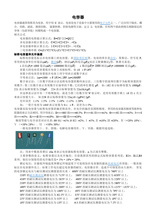
电容器电容器通常简称其为电容,用字母C表示。
电容是电子设备中大量使用的电子元件之一,广泛应用于隔直,耦合,旁路,滤波,调谐回路,能量转换,控制电路等方面。
定义2:电容器,任何两个彼此绝缘且相隔很近的导体(包括导线)间都构成一个电容器。
相关公式电容器的电势能计算公式:E=CU^2/2=QU/2多电容器并联计算公式:C=C1+C2+C3+…+Cn多电容器串联计算公式:1/C=1/C1+1/C2+…+1/Cn三电容器串联C=(C1*C2*C3)/(C1*C2+C2*C3+C1*C3)标称电容量和允许偏差标称电容量是标志在电容器上的电容量。
在国际单位制里,电容的单位是法拉,简称法,符号是F,常用的电容单位有毫法(mF)、微法(μF)、纳法(nF)和皮法(pF)(皮法又称微微法)等,换算关系是:1法拉(F)= 1000毫法(mF)=1000000微法(μF) 1微法(μF)= 1000纳法(nF)= 1000000皮法(pF)。
容量大的电容其容量值在电容上直接标明,如10 μF/16V容量小的电容其容量值在电容上用字母表示或数字表示字母表示法:1m=1000 μF 1P2=1.2PF 1n=1000PF数字表示法:三位数字的表示法也称电容量的数码表示法。
三位数字的前两位数字为标称容量的有效数宇,第三位数宇表示有效数字后面零的个数,它们的单位都是pF。
如:102表示标称容量为1000pF。
221表示标称容量为220pF。
224表示标称容量为22x10(4)pF。
在这种表示法中有一个特殊情况,就是当第三位数字用"9"表示时,是用有效数宇乘上10的-1次方来表示容量大小。
如:229表示标称容量为22x(10-1)pF=2.2pF。
允许误差±1% ±2% ±5% ±10% ±15% ±20%如:一瓷片电容为104J表示容量为0.1 μF、误差为±5%。


各种贴片电容容值规格参数表各种贴片电容容值表X7R贴片电容简述X7R贴片电容属于EIA规定的Class 2类材料的电容。
它的容量相对稳定。
X7R贴片电容特性具有较高的电容量稳定性,在-55℃~125℃工作温度范围内,温度特性为±15%。
层叠独石结构,具有高可靠性。
优良的焊接性和和耐焊性,适用于回流炉和波峰焊。
应用于隔直、耦合、旁路、鉴频等电路中。
X7R贴片电容容量范围厚度与符号对应表0201~1206 X7R贴片电容选型表1210~2225 X7R贴片电容选型表NPO COG 贴片电容容量规格表默认分类2009-07-15 16:28 阅读354 评论1字号:大大中中小小NPO(COG)贴片电容属于Class 1温度补偿型电容。
它的容量稳定,几乎不随温度、电压、时间的变化而变化。
尤其适用于高频电子电路。
具有最高的电容量稳定性,在-55℃~125℃工作温度范围内,温度特性为:0±30ppm/℃(COG)、0±60ppm/℃(COH)。
层叠独石结构,具有高可靠性。
优良的焊接性和和耐焊性,适用于回流炉和波峰焊。
应用于各种高频电路,如:振荡、计时电路等。
我们把用来制造片式多层瓷介电容(MLCC)的陶瓷叫电容器瓷。
这里所说的瓷介就是用电容器瓷制成的陶瓷介质。
大家知道,陶瓷是一类质硬、性脆的无机烧结体。
就其显微结构而论,大都具有多晶多相结构。
其性能往往决定于其成份和结构。
当配方确定之后,能否达到预期的效果,关键取决于制造陶瓷粉料的工艺。
按其用途可以分为三类:①高频热补偿电容器瓷(UJ、SL);②高频热稳定电容器瓷(NPO);③低频高介电容器瓷(X7R、Y5V、Z5U)。
按温度系数分可以分为两类:①负温度系数电容器瓷(即高频热补偿电容器瓷);②正温度系数电容器瓷(即平时我们常说的COG、X7R、Y5V瓷料)。
按工作频率可以分为三类:低频、高频、微波介质。
高频热补偿、热稳定电容器瓷是专供Ⅰ类瓷介电容器作介质用,其瓷料主要成分是MgTiO3、CaTiO3、SrTiO3和TiO2再加入适量的稀土类氧化物等配制而成。


各种贴片电容容值表X7R贴片电容简述X7R贴片电容属于EIA规定的Class 2类材料的电容。
它的容量相对稳定。
X7R贴片电容特性具有较高的电容量稳定性,在-55℃~125℃工作温度范围内,温度特性为±15%。
层叠独石结构,具有高可靠性。
优良的焊接性和和耐焊性,适用于回流炉和波峰焊。
应用于隔直、耦合、旁路、鉴频等电路中。
X7R贴片电容容量范围厚度与符号对应表符号A C E G J K M N P Q X Y Z最大厚度毫米(英寸)0201~1206 X7R贴片电容选型表封装尺020040060080120125112*********工作电2011125102050100A150A220330AJJJKJCGGJJ470ACGGJJJJJJK680电容(pFGGJJJJJJC1000AK1500CGGJJJJJJJJJJJJM2200GGJJJJJCCJJJJJJ3300JMCGJJJJJJJ4700JJJJJMJ JG J J J J CC P6800 J J J J J JJ J J J J J J G J J J CJ J PC G G J J J J J J J J J J J MC G MJ JJJJ J J J JJ MJ G M 电容量 J J J J J J J J MG G (uF)J J J J M J J J J J MJJJ J J G JJ J PJG G GJ J J J J J J J MJ J J J J J J GG J J M J J J JJ J M M M MN M M M MN M MQ M N MPQ1625501016255010010162550工作电压 1610020010162550100200500 0603080512060201封装尺寸04021210~2225 X7R贴片电容选型表封装尺121181182222222 1125102050510205051051020工作电510 10001500JJJJJJM2200电容(pF3300JJJJJJM4700JJJJJJM6800JJJJJJMKKKKMMXXXXMPJJJJJJPKKKPMMXXXXMPJJJJJJKKKXMMXXXXMPJJJJJJKKKZMMXXXXMPJJJJJMKKKMMXXXXMPJJJJMKKPMMXXXXMP电容(uFMJJZMKMPXXXMJJMMMMZKPMMXXXMPZMMMXZPNNXPNNMMXQZ1010162550工作电压 100200500501002005005010050100200501002225 封装尺寸1825181212102220NPO COG 贴片电容容量规格表默认分类 2009-07-15 16:28 阅读354 评论1字号:大大中中小小NPO贴片电容简述NPO(COG)贴片电容属于Class 1温度补偿型电容。
常用电阻、电容标准值国家标准规定了电阻的阻值按其精度分为两大系列,分别为E-24系列和E-96 系列,E-24系列精度为5%,E-96系列为1%,在这两种系列之外的电阻为非标电阻,较难采购。
下面列出了常用的5%和1%精度电阻的标称值,供大家设计时参考。
精度为5%的碳膜电阻,以欧姆为单位的标称值:1.0 5.6 33 160 820 3.9K 20K 100K 510K2.7M1.1 6.2 36 180 910 4.3K 22K 110K 560K 3M1.2 6.8 39 200 1K 4.7K 24K 120K 620K 3.3M1.3 7.5 43 220 1.1K 5.1K 27K 130K 680K3.6M1.5 8.2 47 240 1.2K 5.6K 30K 150K 750K 3.9M1.6 9.1 51 270 1.3K 6.2K 33K 160K 820K 4.3M1.8 10 56 300 1.5K 6.6K 36K 180K 910K 4.7M2.0 11 62 330 1.6K 7.5K 39K 200K 1M 5.1M2.2 12 68 360 1.8K 8.2K 43K 220K 1.1M 5.6M2.4 13 75 390 2K 9.1K 47K 240K 1.2M 6.2M2.7 15 82 430 2.2K 10K 51K 270K 1.3M 6.8M3.0 16 91 470 2.4K 11K 56K 300K 1.5M 7.5M3.3 18 100 510 2.7K 12K 62K 330K 1.6M 8.2M3.6 20 110 560 3K 13K 68K 360K 1.8M 9.1M3.9 22 120 620 3.2K 15K 75K 390K 2M 10M4.3 24 130 680 3.3K 16K 82K 430K 2.2M 15M4.7 27 150 750 3.6K 18K91K 470K 2.4M 22M5.1 30精度为1%的金属膜电阻,以欧姆为单位的标称值:10 33 100 332 1K 3.32K 10.5K 34K 107K 357K10.2 33.2 102 340 1.02K 3.4K 10.7K 34.8K 110K 360K10.5 34 105 348 1.05K 3.48K 11K 35.7K 113K 365K10.7 34.8 107 350 1.07K 3.57K 11.3K 36K 115K 374K11 35.7 110 357 1.1K 3.6K 11.5K 36.5K 118K 383K11.3 36 113 360 1.13K 3.65K 11.8K 37.4K 120K 390K11.5 36.5 115 365 1.15K 3.74K 12K 38.3K 121K 392K11.8 37.4 118 374 1.18K 3.83K 12.1K 39K 124K 402K12 38.3 120 383 1.2K 3.9K 12.4K 39.2K 127K 412K12.1 39 121 390 1.21K 3.92K 12.7K 40.2K 130K 422K12.4 39.2 124 392 1.24K 4.02K 13K 41.2K 133K 430K12.7 40.2 127 402 1.27K 4.12K13.3K 42.2K 137K 432K13 41.2 130 412 1.3K 4.22K 13.7K 43K 140K 442K13.3 42.2 133 422 1.33K 4.32K 14K 43.2K 143K 453K13.7 43 137 430 1.37K 4.42K 14.3K 44.2K 147K 464K14 43.2 140 432 1.4K 4.53K 14.7K 45.3K 150K 470K14.3 44.2 143 442 1.43K 4.64K 15K 46.4K 154K 475K14.7 45.3 147 453 1.47K 4.7K 15.4K 47K 158K487K15 46.4 150 464 1.5K 4.75K 15.8K 47.5K 160K 499K15.4 47 154 470 1.54K 4.87K 16K 48.7K 162K 511K15.8 47.5 158 475 1.58K 4.99K 16.2K 49.9K 165K 523K16 48.7 160 487 1.6K 5.1K 16.5K 51K 169K 536K16.2 49.9 162 499 1.62K 5.11K 16.9K 51.1K 174K 549K16.5 51 165 510 1.65K 5.23K 17.4K 52.3K 178K 560K16.9 51.1 169 511 1.69K 5.36K 17.8K 53.6K 180K 562K17.4 52.3 174 523 1.74K 5.49K 18K 54.9K 182K 576K17.8 53.6 178 536 1.78K 5.6K 18.2K 56K 187K 590K18 54.9 180 549 1.8K 5.62K 18.7K 56.2K 191K 604K18.2 56 182 560 1.82K 5.76K 19.1K 57.6K 196K 619K18.7 56.2 187 562 1.87K 5.9K 19.6K 59K 200K 620K19.1 57.6 191 565 1.91K 6.04K20K 60.4K 205K 634K19.6 59 196 578 1.96K 6.19K 20.5K 61.9K 210K 649K20 60.4 200 590 2K 6.2K 21K 62K 215K 665K20.5 61.9 205 604 2.05K 6.34K 21.5K 63.4K 220K 680K21 62 210 619 2.1K 6.49K 22K 64.9K 221K 681K21.5 63.4 215 620 2.15K 6.65K 22.1K 66.5K 226K 698K22 64.9 220 634 2.2K 6.8K 22.6K 68K 232K715K22.1 66.5 221 649 2.21K 6.81K 23.2K 68.1K 237K 732K22.6 68 226 665 2.26K 6.98K 23.7K 69.8K 240K 750K23.2 68.1 232 680 2.32K 7.15K 24K 71.5K 243K 768K23.7 69.8 237 681 2.37 7.32K 24.3K 73.2K 249K 787K24 71.5 240 698 2.4K 7.5K 24.9K 75K 255K 806K24.3 73.2 243 715 2.43K 7.68K 25.5K 76.8K 261K 820K24.7 75 249 732 2.49K 7.87K 26.1K 78.7K 267K 825K24.9 75.5 255 750 2.55K 8.06K 26.7K 80.6K 270K 845K25.5 76.8 261 768 2.61K 8.2K 27K 82K 274K 866K26.1 78.7 267 787 2.67K 8.25K 27.4K 82.5K 280K 887K26.7 80.6 270 806 2.7K 8.45K 28K 84.5K 287K 909K27 82 274 820 2.74K 8.66K 28.7K 86.6K 294K 910K27.4 82.5 280 825 2.8K 8.8K29.4K 88.7K 300K 931K28 84.5 287 845 2.87K 8.87K 30K 90.9K 301K 953K28.7 86.6 294 866 2.94K 9.09K 30.1K 91K 309K 976K29.4 88.7 300 887 3.0K 9.1K 30.9K 93.1K 316K 1.0M30 90.9 301 909 3.01K 9.31K 31.6K 95.3K 324K 1.5M30.1 91 309 910 3.09K 9.53K 32.4K 97.6K 330K 2.2M30.9 93.1 316 931 3.16K 9.76K 33K 100K 332K31.6 95.3 324 953 3.24K 10K 33.2K 102K 340K32.4 97.6 330 976 3.3K 10.2K 33.6K 105K 348K电容器标称电容值:E24 E12 E6 E24 E12 E61.0 1.0 1.0 3.3 3.3 3.31.1 3.61.2 1.2 3.9 3.91.3 4.31.5 1.5 1.5 4.7 4.7 4.71.6 5.11.8 1.8 5.6 5.62.0 6.22.2 2.2 2.2 6.8 6.8 6.82.4 7.52.7 2.7 8.2 8.23.0 9.1注:用表中数值再乘以10n来表示电容器标称电容量,n为正或负整数。
kmh 电容-概述说明以及解释1.引言1.1 概述电容是一种基本的电子元件,广泛应用于各个领域,包括电子器件、通信设备和电力系统等。
它具有存储电能的能力,能够在电路中储存和释放电荷。
KMh(Kilomicrofarad)电容是电容的计量单位,表示一百万分之一法拉德。
它通常用于大容量和高压的应用,比如电力电子和工业控制领域。
KMh电容具有许多优点,其中之一是其高容量。
由于其容量较大,它能够存储更多的电能,从而提供更稳定的电流和电压输出。
此外,KMh电容还具有出色的耐压能力。
它能够承受较高的电压,不易受到短路或击穿等问题的影响。
因此,在高压应用中,KMh电容是一种非常理想的选择。
KMh电容还具备良好的稳定性和长寿命特性。
它的内阻比较小,能够稳定地工作在高频率和高电压下。
同时,它的寿命更长,能够保持其性能稳定性,降低更换和维护的频率和成本。
值得一提的是,KMh电容在电子设备中的应用非常广泛。
它常用于直流电源滤波、隔离、耦合和电压调整等方面。
此外,在电力系统中,KMh 电容也被广泛应用于无功补偿、谐波滤波和电力因数校正等关键领域。
综上所述,KMh电容作为一种高容量、高耐压、稳定性好且寿命长的电容,具有广泛的应用前景。
它在电子器件和电力系统中的作用不可忽视,为各个领域的电路设计和电能管理带来了便利和效益。
同时,随着科技的不断发展,我们可以预见KMh电容将继续在未来发挥更重要的作用。
1.2 文章结构文章结构部分主要描述了本文的组织结构和各个部分的内容概要。
本文分为引言、正文和结论三个主要部分。
1. 引言部分主要包括对kmh电容的简要介绍和背景说明。
将介绍电容的基本概念和作用,以及kmh电容在电子行业的重要性和应用领域。
2. 正文部分将深入探讨kmh电容的相关内容。
主要包括以下几个方面:- kmh电容的特点和优势:介绍kmh电容相比其他类型电容的特点,如高温稳定性、低功耗和长寿命等。
- kmh电容的制造工艺:详细介绍kmh电容的制造过程和相关的材料选用。
Eaton 281307Eaton Moeller series NZM - Molded Case Circuit Breaker. Circuit-breaker, 3p, 125A, H2-M125Allgemeine spezifikationEaton Moeller series NZM molded case circuit breaker thermo-magnetic281307149 mm184 mm 105 mm 2.334 kg RoHS conform IEC IEC/EN 609474015082813079NZMH2-M125Product NameCatalog NumberProduct Length/Depth Product Height Product Width Product Weight Compliances Certifications EANModel Code125 AIs the panel builder's responsibility. The specifications for the switchgear must be observed.5 kA130 kAMeets the product standard's requirements.Is the panel builder's responsibility. The specifications for the switchgear must be observed.Built-in device fixed built-in techniqueFixed125 ADoes not apply, since the entire switchgear needs to be evaluated.Min. 2 segments of 9 mm x 0.8 mm at box terminalMax. 8 segments of 24 mm x 1 mm (2x) at box terminal Max. 10 segments of 16 mm x 0.8 mm at box terminalMax. 10 segments of 24 mm x 0.8 mm at rear-side connection (punched)Min. 2 segements of 16 mm x 0.8 mm at rear-side connection (punched)Rocker leverMeets the product standard's requirements.40 °C eaton-circuit-breaker-let-through-current-nzm-mccb-characteristic-curve-005.epseaton-circuit-breaker-characteristic-power-defense-mccb-characteristic-curve-037.epsMH2-M125il01206006z2015_11.pdfDas neue digitale NZM-Sortiment - In Kurze verfugbar DE Vorstellung des neuen digitalen Leistungsschalter NZMDA-CD-nzm2_3pDA-CS-nzm2_3peaton-manual-motor-starters-starter-msc-r-reversing-starter-wiring-diagram.epseaton-manual-motor-starters-starter-nzm-mccb-wiring-diagram.epseaton-nzm-technical-information-sheeteaton-circuit-breaker-nzm-mccb-dimensions-019.epsRated operational current for specified heat dissipation (In) 10.11 Short-circuit ratingRated short-circuit breaking capacity Ics (IEC/EN 60947) at 690 V, 50/60 HzRated short-circuit breaking capacity Icu (IEC/EN 60947) at 400/415 V, 50/60 Hz10.4 Clearances and creepage distances10.12 Electromagnetic compatibilityMounting MethodAmperage Rating10.2.5 LiftingTerminal capacity (copper strip)Handle type10.2.3.1 Verification of thermal stability of enclosuresAmbient storage temperature - min Characteristic curveeCAD model Installationsanleitung Installationsvideos mCAD modelSchaltpläneTechnische Datenblätter ZeichnungenFitted with:Thermal protectionProtection against direct contactFinger and back-of-hand proof to VDE 0106 part 100Terminal capacity (copper busbar)Max. 24 mm x 8 mm direct at switch rear-side connectionMin. 16 mm x 5 mm direct at switch rear-side connectionM8 at rear-side screw connection10.8 Connections for external conductorsIs the panel builder's responsibility.Special featuresMaximum back-up fuse, if the expected short-circuit currents at the installation location exceed the switching capacity of the circuit breaker (Rated short-circuit breaking capacity Icn) Rated current = rated uninterrupted current: 125 A Tripping class 10 A IEC/EN 60947-4-1, IEC/EN 60947-2 The circuit-breaker fulfills all requirements for AC-3 switching category.Ambient operating temperature - max70 °CClimatic proofingDamp heat, cyclic, to IEC 60068-2-30Damp heat, constant, to IEC 60068-2-78Terminal capacity (aluminum stranded conductor/cable)25 mm² - 50 mm² (1x) direct at switch rear-side connection25 mm² - 50 mm² (2x) direct at switch rear-side connection25 mm² - 185 mm² (1x) at tunnel terminalTerminal capacity (copper stranded conductor/cable)25 mm² - 70 mm² (2x) at box terminal25 mm² - 185 mm² (1x) direct at switch rear-side connection25 mm² - 185 mm² (1x) at box terminal25 mm² - 185 mm² (1x) at 1-hole tunnel terminal25 mm² - 70 mm² (2x) direct at switch rear-side connectionLifespan, electrical6500 operations at 400 V AC-310000 operations at 400 V AC-17500 operations at 690 V AC-16500 operations at 415 V AC-35000 operations at 690 V AC-310000 operations at 415 V AC-1Electrical connection type of main circuitScrew connectionShort-circuit total breaktime< 10 msRated impulse withstand voltage (Uimp) at main contacts8000 VRated short-circuit breaking capacity Ics (IEC/EN 60947) at 400/415 V, 50/60 Hz130 kA10.9.3 Impulse withstand voltageIs the panel builder's responsibility.Utilization categoryA (IEC/EN 60947-2)Number of polesThree-poleAmbient operating temperature - min-25 °C10.6 Incorporation of switching devices and componentsDoes not apply, since the entire switchgear needs to be evaluated.10.5 Protection against electric shockDoes not apply, since the entire switchgear needs to be evaluated.Terminal capacity (control cable)0.75 mm² - 2.5 mm² (1x)0.75 mm² - 1.5 mm² (2x)Equipment heat dissipation, current-dependent27.61 WInstantaneous current setting (Ii) - min1000 A10.13 Mechanical functionThe device meets the requirements, provided the information in the instruction leaflet (IL) is observed.10.2.6 Mechanical impactDoes not apply, since the entire switchgear needs to be evaluated.10.9.4 Testing of enclosures made of insulating materialIs the panel builder's responsibility.Rated operational current99 A (400 V AC-3)Rated short-circuit breaking capacity Ics (IEC/EN 60947) at 230 V, 50/60 Hz150 kAApplicationUse in unearthed supply systems at 690 V10.3 Degree of protection of assembliesDoes not apply, since the entire switchgear needs to be evaluated.Rated short-circuit making capacity Icm at 240 V, 50/60 Hz330 kARated short-circuit breaking capacity Ics (IEC/EN 60947) at 440 V, 50/60 Hz130 kADegree of protection (IP), front sideIP40 (with insulating surround)IP66 (with door coupling rotary handle)Rated short-circuit making capacity Icm at 525 V, 50/60 Hz105 kARated short-circuit making capacity Icm at 690 V, 50/60 Hz40 kAInstantaneous current setting (Ii) - max1750 AOverload current setting (Ir) - min100 A10.2.3.2 Verification of resistance of insulating materials to normal heatMeets the product standard's requirements.10.2.3.3 Resist. of insul. mat. to abnormal heat/fire by internal elect. effectsMeets the product standard's requirements.Lifespan, mechanical20000 operationsOverload current setting (Ir) - max125 AVoltage rating690 V - 690 VTerminal capacity (copper solid conductor/cable)10 mm² - 16 mm² (1x) at box terminal6 mm² - 16 mm² (2x) direct at switch rear-side connection6 mm² - 16 mm² (2x) at box terminal10 mm² - 16 mm² (1x) direct at switch rear-side connection16 mm² (1x) at tunnel terminalDegree of protection (terminations)IP10 (tunnel terminal)IP00 (terminations, phase isolator and strip terminal)10.9.2 Power-frequency electric strengthIs the panel builder's responsibility.Short-circuit release non-delayed setting - min1000 ADegree of protectionIP20IP20 (basic degree of protection, in the operating controls area)Overvoltage categoryIIIRated short-time withstand current (t = 1 s)1.9 kARated impulse withstand voltage (Uimp) at auxiliary contacts 6000 VTerminal capacity (aluminum solid conductor/cable)10 mm² - 16 mm² (2x) direct at switch rear-side connection16 mm² (1x) at tunnel terminal10 mm² - 16 mm² (1x) direct at switch rear-side connectionSwitch off techniqueThermomagneticRated short-time withstand current (t = 0.3 s)1.9 kAAmbient storage temperature - max70 °CRated short-circuit breaking capacity Ics (IEC/EN 60947) at 525 V, 50/60 Hz37.5 kAOptional terminalsBox terminal. Connection on rear. Tunnel terminalRelease systemThermomagnetic releasePollution degree310.7 Internal electrical circuits and connectionsIs the panel builder's responsibility.Rated operating power at AC-3, 230 V37 kW10.10 Temperature riseThe panel builder is responsible for the temperature rise calculation. Eaton will provide heat dissipation data for the devices.FunctionsMotor protectionShort-circuit release non-delayed setting - max1750 AStandard terminalsScrew terminalRated short-circuit making capacity Icm at 400/415 V, 50/60 Hz 330 kARated operating power at AC-3, 400 V55 kWTypeCircuit breaker10.2.2 Corrosion resistanceMeets the product standard's requirements.10.2.4 Resistance to ultra-violet (UV) radiationMeets the product standard's requirements.10.2.7 InscriptionsMeets the product standard's requirements.Rated short-circuit making capacity Icm at 440 V, 50/60 Hz 286 kAIsolation500 V AC (between auxiliary contacts and main contacts)300 V AC (between the auxiliary contacts)Number of operations per hour - max120Circuit breaker frame typeNZM2Direction of incoming supplyAs requiredShock resistance20 g (half-sinusoidal shock 20 ms)Eaton Konzern plc Eaton-Haus30 Pembroke-Straße Dublin 4, Irland © 2023 Eaton. Alle Rechte vorbehalten. Eaton ist eine eingetrageneMarke.Alle anderen Warenzeichen sindEigentum ihrer jeweiligenBesitzer./socialmedia1000 VRated insulation voltage (Ui)。