工程有限元分析英文课件:工程中的有限元法
- 格式:ppt
- 大小:4.48 MB
- 文档页数:95

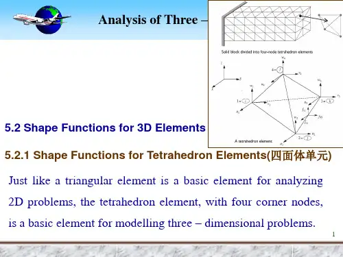
有限元分析经典课件1. 简介有限元分析(Finite Element Analysis, FEA)是一种以数值模拟方法为基础,通过离散化处理求解结构力学问题的工程方法。
本课件将介绍有限元分析的基本原理和常用的应用领域。
2. 有限元分析的基本原理2.1 有限元方法概述有限元方法(Finite Element Method, FEM)是有限元分析的基础理论和计算方法。
本部分将介绍有限元方法的基本概念、基本步骤、离散化处理等内容。
2.2 有限元网格划分有限元网格划分是有限元分析的关键步骤,它将结构离散化为有限个小单元。
本部分将介绍有限元网格划分的方法、常用网格类型以及网格质量评价的方法。
2.3 有限元方程与加载有限元方程是描述结构力学问题的关键方程。
本部分将介绍有限元方程的推导过程,以及加载条件的处理方法。
2.4 有限元解与后处理有限元解是通过有限元分析得到的结构响应结果。
本部分将介绍有限元解的计算方法以及后处理方法,包括位移、应力、应变等结果的计算和可视化展示。
3. 有限元分析的应用案例3.1 结构力学分析结构力学分析是有限元分析的主要应用之一。
本部分将通过实例演示有限元分析在结构力学分析中的具体应用,包括静力学分析、动力学分析等。
3.2 热力学分析热力学分析是有限元分析的另一个重要应用领域。
本部分将通过实例演示有限元分析在热力学分析中的具体应用,包括热传导、热稳定性等问题的分析。
3.3 流体力学分析流体力学分析是有限元分析的扩展应用领域之一。
本部分将通过实例演示有限元分析在流体力学分析中的具体应用,包括流体流动、压力分布等问题的分析。
4. 有限元分析软件的介绍有限元分析软件是进行有限元分析的工具,市场上有多种成熟的有限元分析软件可供选择。
本部分将介绍一些常用的有限元分析软件,包括Ansys、Abacus等。
5. 总结有限元分析作为一种重要的数值模拟方法,已广泛应用于不同领域的工程问题。
本课件从理论原理到实际应用都进行了全面的介绍,相信对有限元分析的学习和应用都有很大帮助。
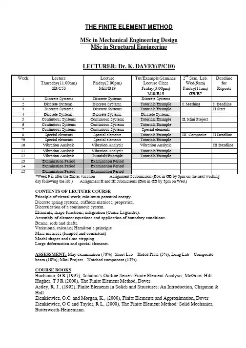
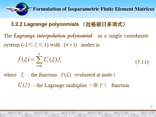
MSc in Mechanical Engineering Design MSc in Structural Engineering LECTURER: Dr. K. DAVEY(P/C10)Week LectureThursday(11.00am)SB/C53LectureFriday(2.00pm)Mill/B19Tut/Example/Seminar/Lecture ClassFriday(3.00pm)Mill/B192nd Sem. Lab.Wed(9am)Friday(11am)GB/B7DeadlineforReports1 DiscreteSystems DiscreteSystems DiscreteSystems2 Discrete Systems. Discrete Systems. Tutorials/Example I.Meshing I.Deadline 3 Discrete Systems Discrete Systems Tutorials/Example IIStart4 Discrete Systems. Discrete Systems. DiscreteSystems.5 Continuous Systems Continuous Systems Tutorials/Example II. Mini Project6 Continuous Systems Continuous Systems Tutorials/Example7 Continuous Systems Continuous Systems Special elements8 Special elements Special elements Tutorials/Example III.Composite IIDeadline *9 Special elements Special elements Tutorials/Example10 Vibration Analysis Vibration Analysis Vibration Analysis III Deadline11 Vibration Analysis Vibration Analysis Tutorials/Example12 VibrationAnalysis Tutorials/Example Tutorials/Example13 Examination Period Examination Period14 Examination Period Examination Period15 Examination Period Examination Period*Week 9 is after the Easter vacation Assignment I submission (Box in GB by 3pm on the next workingday following the lab.) Assignment II and III submissions (Box in GB by 3pm on Wed.)CONTENTS OF LECTURE COURSEPrinciple of virtual work; minimum potential energy.Discrete spring systems, stiffness matrices, properties.Discretisation of a continuous system.Elements, shape functions; integration (Gauss-Legendre).Assembly of element equations and application of boundary conditions.Beams, rods and shafts.Variational calculus; Hamilton’s principleMass matrices (lumped and consistent)Modal shapes and time-steppingLarge deformation and special elements.ASSESSMENT: May examination (70%); Short Lab – Holed Plate (5%); Long Lab – Compositebeam (10%); Mini Project – Notched component (15%).COURSE BOOKSBuchanan, G R (1995), Schaum’s Outline Series: Finite Element Analysis, McGraw-Hill.Hughes, T J R (2000), The Finite Element Method, Dover.Astley, R. J., (1992), Finite Elements in Solids and Structures: An Introduction, Chapman &HallZienkiewicz, O.C. and Morgan, K., (2000), Finite Elements and Approximation, DoverZienkiewicz, O C and Taylor, R L, (2000), The Finite Element Method: Solid Mechanics,Butterworth-Heinemann.IntroductionThe finite element method (FEM) is a numerical technique that can be applied to solve a range of physical problems. The method involves the discretisation of the body (domain) of interest into subregions, which are known as elements. This enables a continuum problem to be described by a finite system of equations. In the field of solid mechanics the FEM is undoubtedly the solver of choice and its use has revolutionised design and analysis approaches. Many commercial FE codes are available for many types of analyses such as stress analysis, fluid flow, electromagnetism, etc. In fact if a physical phenomena can be described by differential or integral equations, then the FE approach can be used. Many universities, research centres and commercial software houses are involved in writing software. The differences between using and creating code are outlined below:(A) To create FE software1. Confirm nature of physical problem: solid mechanics; fluid dynamics; electromagnetic; heat transfer; 1-D, 2-D, 3-D; Linear; non-linear; etc.2. Describe mathematically: governing equations; loading conditions.3. Derive element equations: convert governing equations into algebraic form; select trial functions; prepare integrals for numerical evaluation.4. Assembly and solve: assemble system of equations; application of loads; solution of equations.5. Compute:6. Process output: select type of data; generate related data; display meaningfully and attractively.(B) To use FE software1. Define a specific problem: geometry; physical properties; loads.2. Input data to program: geometry of domain, mesh generation; physical properties; loads-interior and boundary.3. Compute:4. Process output: select type of data; generate related data; display meaningfully and attractively.DISCRETE SYSTEMSSTATICSThe finite element involves the transformation of a continuous system (infinite degrees of freedom) into a discrete system (finite degrees of freedom). It is instructive therefore to examine the behaviour of simple discrete systems and associated variational methods as this provides real insight and understanding into the more complicated systems arising from the finite element method.Work and Strain energyFLuxConsider a metal bar of uniform cross section, A , fixed at one end (unrestrained laterally) and subjected to an axial force, F , at the other.Small deflection theory is assumed to apply unless otherwise stated.The work done, W , by the applied force F is .a ()∫′′=uau d u F WIt is worth mentioning at this early stage that it is not always possible to express work in this manner for various reasons associated with reversibility and irreversibility. (To be discussed later)The work done, W , by the internal forces, denoted strain energy , is se22200se ku 21u L EA 2121EAL d EAL d AL W ==ε=ε′ε′=ε′σ=∫∫εεwhere ε=u L and stiffness k EA L=.The principle of virtual workThe principle of virtual work states that the variation in strain energy is equal to the variation in the work done by applied forces , i.e.()u F u u d u F du d W u ku u ku 21du d ku 21W u0a 22se δ=δ⎟⎟⎠⎞⎜⎜⎝⎛′′=δ=δ=δ⎟⎠⎞⎜⎝⎛=⎟⎠⎞⎜⎝⎛δ=δ∫()0u F ku =δ−⇒Note that use has been made of the relationship δf dfduu =δ where f is an arbitrary functional of u . In general displacement u is a function of position (x say) and it is understood that ()x u δ means a change in ()u x with xfixed. Appreciate that varies with from zero to ()'u F 'u ()u F F = in the above integral.Bearing in mind that δ is an arbitrary variation; then this equation is satisfied if and only if F , which is as expected. Before going on to apply the principle of virtual work to a continuous system it is worth investigating discrete systems further. This is because the finite element formulation involves the transformation of a continuous system into a discrete one. u ku =Spring systemsConsider a single spring with stiffness independent of deflection. Then, 2F21u1F1u2k()()⎟⎟⎠⎞⎜⎜⎝⎛⎥⎦⎤⎢⎣⎡−−=−=2121212se u u k k k k u u 21u u k 21W()()()⎟⎟⎠⎞⎜⎜⎝⎛⎥⎦⎤⎢⎣⎡−−δδ=δ−δ−=δ21211212se u u k k k k u u u u u u k W()⎟⎟⎠⎞⎜⎜⎝⎛δδ=δ+δ=δ21212211a F F u u u F u F W , where ()111u F F = and ()222u F F =.Note here that use has been made of the relationship δ∂∂δ∂∂δf f u u f u u =+1122, where f is an arbitrary functional of and . Observe that in this case is a functional of 1u u 2W se u u u 2121=−, so()()(121212*********se se u u u u k u u ku 21du d u du dW W δ−δ−=−δ⎟⎠⎞⎜⎝⎛=δ=δ).The principle of virtual work provides,()()()()0F u u k u F u u k u 0W W 21221121a se =−−δ+−−−δ⇒=δ−δand since δ and δ are arbitrary we have. u 1u 2F ku ku 11=−2u 2 F ku k 21=−+represented in matrix form,u F K u u k k k k F F 2121=⎟⎟⎠⎞⎜⎜⎝⎛⎥⎦⎤⎢⎣⎡−−=⎟⎟⎠⎞⎜⎜⎝⎛=where K is known as the stiffness matrix . Note that this matrix is singular (det K k k =−=220) andsymmetric (K K T=). The symmetry is a result of the fact that a unit deflection at node 1 results in a force at node 2 which is the same in magnitude at node 1 if node 2 is moved by the same amount.Could also have arrived at equation above via()⎟⎟⎠⎞⎜⎜⎝⎛⎥⎦⎤⎢⎣⎡−−=⎟⎟⎠⎞⎜⎜⎝⎛⇒=⎟⎟⎠⎞⎜⎜⎝⎛⎟⎟⎠⎞⎜⎜⎝⎛⎥⎦⎤⎢⎣⎡−−−⎟⎟⎠⎞⎜⎜⎝⎛δδ=δ−δ2121211121a se u u k k k k F F 0u u k k k k F F u u W WBoundary conditionsWith the finite element method the application of displacement constraint boundary conditions is performed after the equations are assembled. It is an interest to examine the implications of applying and not applying the displacement boundary constraints prior to applying the principle of virtual work. Consider then the single spring element above but fixed at node 1, i.e. 0u 1=. Ignoring the constraint initially gives()212se u u k 21W −=, ()()1212se u u u u k W δ−δ−=δ and 2211a u F u F W δ+δ=δ.The principle of virtual work gives 2211ku ku ku F −=−= and 2212ku ku ku F =+−=, on applicationof the constraint. Note that is the force required at node 1 to prevent the node moving and is the reaction force.21ku F −=21ku F =−Applying the constraint straightaway gives 22se ku 21W =, 22se u ku W δ=δ and 22a u F W δ=δ. The principle of virtual work gives with no information about the reaction force at node 1.22ku F =Exam Standard Question:The spring-mass system depicted in the Figure consists of three massless springs, which are attached to fixed boundaries by means of pin-joints at nodes 1, 3 and 5. The springs are connected to a rigid bar by means of pin-joints at nodes 2 and 4. The rigid bar is free to rotate about pivot A. Nodes 2 and 4 are distances and below pivot A, respectively. Each spring has the same stiffness k. Node 2 is subjected to an external horizontal force F 2/l 4/l 2. All deflections can be assumed to be small.(i) Write expressions for the extension of each spring in terms of the displacement of node 2.(ii) In terms of the degrees of freedom at node 2, write expressions for the total strain energy W of the spring-mass system. In addition, specify the variation in work done se a W δ resulting from the application of the force.2F (iii) Use Use the principle of virtual work to find a relationship between the magnitude of and the horizontal components of displacement at node 2.2F (iv) Use the principle of virtual work to show that the net vertical force imposed by the springs on the rigid-bar at node 2 is zero.Solution:(i) Directional vectors for springs are: 2112e 21e 23e +=, 2132e 21e 23e +−= and 145e e =. Extensions for bottom springs are: 221212u 23u e =⋅=δ, 223232u 23u e −=⋅=δ.Note that 2u u 24=, so 2u245−=δ.(ii)()2222222245232212se ku 87u 212323k 21k 21W =⎟⎟⎠⎞⎜⎜⎝⎛⎟⎠⎞⎜⎝⎛+⎟⎟⎠⎞⎜⎜⎝⎛−+⎟⎟⎠⎞⎜⎜⎝⎛=δ+δ+δ=, 222u F W δ=δ(iii) 2222a 22se ku 47F u F W u ku 47W =⇒δ=δ=δ=δ(iv) Need additional displacement degree of freedom at node 2. Let 22122e v e u u += and note that2221212v 21u 23u e +=⋅=δ and 2223232v 21u 23u e +−=⋅=δ.()⎟⎟⎠⎞⎜⎜⎝⎛⎟⎟⎠⎞⎜⎜⎝⎛+−+⎟⎟⎠⎞⎜⎜⎝⎛+=δ+δ=222222232212se v 21u 23v 21u 23k 21k 21W ⎟⎟⎠⎞⎜⎜⎝⎛⎟⎟⎠⎞⎜⎜⎝⎛δ+δ−⎟⎟⎠⎞⎜⎜⎝⎛+−+⎟⎟⎠⎞⎜⎜⎝⎛δ+δ⎟⎟⎠⎞⎜⎜⎝⎛+=δ22222222se v 21u 23v 21u 23v 21u 23v 21u 23k W Setting and gives0v 2=0u 2=δ2vert 222222se v F v 0v 21u 23v 21u 23k W δ=δ=⎟⎟⎠⎞⎜⎜⎝⎛⎟⎠⎞⎜⎝⎛δ⎟⎟⎠⎞⎜⎜⎝⎛−+⎟⎠⎞⎜⎝⎛δ⎟⎟⎠⎞⎜⎜⎝⎛=δ hence . 0F vert 2=Method of Minimum PotentialConsider the expression,()()F u u u TT 21212121c se K 21F F u u u u k k k k u u 21W W P −=⎟⎟⎠⎞⎜⎜⎝⎛−⎟⎟⎠⎞⎜⎜⎝⎛⎥⎦⎤⎢⎣⎡−−=−=where W F and can be considered as a work term with independent of . u F u c =+1122F i u iThe approach of minimising P is known as the method of minimum potential .Note that,()()u F 0F -u u =F u u u +u u K K K K 21W W P T T T T c se =⇒=δδ−δδ=δ−δ=δwhere use has been made of the fact that δδu u =u u T TK K as a result of K 's symmetry.It is useful at this stage to consider the minimisation of an arbitrary functional ()u P where()()3T T O H 21P P u u u u u δ+δδ+∇δ=δand the gradient ∇=P P u i i ∂∂, and the Hessian matrix coefficients H P u u ij i j=∂∂∂2.A stationary point requires that ∇=, i.e.P 0∂∂Pu i=0.Moreover, a minimum point requires that δδu u TH >0 for all δu ≠0 and matrices that possess this property are known as positive definite .Setting P W W K se c T=−=−12u u u F T provides ∇=−=P K u F 0 and H K =.It is a simple matter to check that with u 10= (to prevent rigid body movement) that K is positive definite and this is a property commonly associated with FE stiffness matrices.Exam Standard Question:The spring system depicted in the Figure consists of four massless unstretched springs, which are attached to fixed boundaries by means of pin-joints at nodes 1 to 4. The springs are connected to a slider at node 5. Theslider is constrained to move in a frictionless channel whose axis is to the horizontal. Each spring has the same stiffness k. The slider is subjected to an external force F 0453 whose direction is along the axis of the frictionless channel.(i)The deflection of node 5 can be represented by the vector 25155v u e e u +=, where and areunit orthogonal vectors which are shown in the Figure. Write the components of deflection and in terms of , where is the magnitude of , i.e. e 1e 25u 5v 5U 5U 5u 25U 5u =. Show that the extensions of eachspring, in terms of , are: 5U ()22/31U 515+=δ, ()22/31U 525−=δ, and2/U 54535−=δ−=δ.(ii) In terms of k and write expressions for the total strain energy W of the spring-mass system. Inaddition, specify the variation in work done 5U se a W δ resulting from the application of the force . 5F (iii) Use the principal of virtual work to find a relationship between the magnitude of and thedisplacement at node 5.5F 5U (iv) Use the principal of virtual work to determine an expression for the force imposed by the frictionless channel on the slider.(v)Form a potential energy function for the spring system. Assume here that nodes 1, 3 and 4 are fixed and node 5 is restricted to move in the channel. Use this function to determine the reaction force at node 2.Solution:(i) Directional vectors for springs and channel are: ()2115e e 321e +=, ()2125e e 321e +−=, 135e e −=, 45e e = and (21c 5e e 21e +=). Deflection c 555e U u =, so 2U v u 555==. Extensions springs are: ()3122U u e 551515+=⋅=δ, ()3122U u e 552525−=⋅=δ, 2Uu e 553535−=⋅=δand 2Uu e 554545=⋅=δ(ii)()()()252522245235225215se kU U 83131k 8121k 21W =⎟⎠⎞⎜⎝⎛+−++=δ+δ+δ+δ=, 55a U F W δ=δ(iii)5555a 55se kU 2F U F W U kU 2W =⇒δ=δ=δ=δ(iv) Need additional displacement degree of freedom at node 3. A unit vector perpendicular to the channel is(21p 5e e 21e +−=) and let p 55c 555e V e U u += and note that()()3122V3122U u e 5551515−++=⋅=δ and ()()3122V3122U u e 5552525++−=⋅=δ, 2V 2U u e 5553535+−=⋅=δ and 2V 2U u e 5554545−=⋅=δ()()()()()()()()⎟⎠⎞⎜⎝⎛−+++−+−++=δ+δ+δ+δ=255255255245235225215se V U 831V 31U 31V 31U k 8121k 21W ()()()()()555se V 0V 831313131kU 81W δ=δ−+−+−+=δ, where variation is onlyconsidered and is set to zero. Principle of virtual work .5V δ3V 0F V F V 0W p 55p 55se =⇒δ=δ=δ(v)()3122U u e 551515+=⋅=δ, ()()5552525V 3122Uu u e −−=−⋅=δ, where 2522e V u =. ()()()223333223232233245235225215V F U F U V 3122U 3122U k 21V F U F k 21P −−⎟⎟⎠⎞⎜⎜⎝⎛+⎥⎦⎤⎢⎣⎡−−+⎥⎦⎤⎢⎣⎡+=−−δ+δ+δ+δ=and ()0F V 3122U k V P 2232=−⎥⎦⎤⎢⎣⎡−−−=∂∂, which on setting 0V 2= gives ()⎥⎦⎤⎢⎣⎡−−=3122U k F 32.The reaction is .2F −System AssemblyConsider the following three-spring system 2F 21u 1F 1u 2kF 3F 4u 3u 4k 1k2334()()()234322322121se u u k 21u u k 21u u k 21W −+−+−=,()()()()()()343432323212121se u u u u k u u u u k u u u u k W δ−δ−+δ−δ−+δ−δ−=δ,44332211a u F u F u F u F W δ+δ+δ+δ=δ,and δδ implies that,W W se a −=0u F K u u u u k k 0k k k k 00k k k k 00k k F FF F 43213333222211114321=⎟⎟⎟⎟⎟⎠⎞⎜⎜⎜⎜⎜⎝⎛⎥⎥⎥⎥⎦⎤⎢⎢⎢⎢⎣⎡−−+−−+−−=⎟⎟⎟⎟⎟⎠⎞⎜⎜⎜⎜⎜⎝⎛=where again it is apparent that K is symmetric but also it is banded, i.e. the non-zero coefficients are located around the principal diagonal. This is a property commonly associated with assembled FE stiffness matrices and depends on node connectivity. Note also that the summation of coefficients in individual rows or columns gives zero. The matrix is singular and 0K det =.Note that element stiffness matrices are: , and where on examination of K it is apparent how these are assembled to form K .⎥⎦⎤⎢⎣⎡−−1111k k k k ⎥⎦⎤⎢⎣⎡−−2222k k k k ⎥⎦⎤⎢⎣⎡−−3333k k k kIf a boundary constraint is imposed then row one is removed to give:0u 1=u F K u u u k k 0k k k k 0k k k F F F 432333322221432=⎟⎟⎟⎠⎞⎜⎜⎜⎝⎛⎥⎥⎥⎦⎤⎢⎢⎢⎣⎡−−+−−+=⎟⎟⎟⎠⎞⎜⎜⎜⎝⎛=. If however a boundary constraint (say) is imposed then row one is again removed but a somewhatdifferent answer is obtained: 1u 1=u F K u u u k k 0k k k k 0k k k F F k F 4323333222214312=⎟⎟⎟⎠⎞⎜⎜⎜⎝⎛⎥⎥⎥⎦⎤⎢⎢⎢⎣⎡−−+−−+=⎟⎟⎟⎠⎞⎜⎜⎜⎝⎛+=)Direct FormulationIt is possible to formulate the stiffness matrix directly by moving one node and keeping the others fixed and noting the reactions.The above system can be solved for u , once possible rigid body motion is prevented, by setting u (say) to give 10=⇒=⎟⎟⎟⎠⎞⎜⎜⎜⎝⎛⎥⎥⎥⎦⎤⎢⎢⎢⎣⎡−−+−−+=⎟⎟⎟⎠⎞⎜⎜⎜⎝⎛=u F K u u u k k 0k k k k 0k k k F F F 432333322221432⎟⎟⎟⎠⎞⎜⎜⎜⎝⎛⎥⎥⎥⎦⎤⎢⎢⎢⎣⎡−−+−−+=⎟⎟⎟⎠⎞⎜⎜⎜⎝⎛−4321333322221432F F F k k 0k k k k 0k k k u u uThe inverse stiffness matrix, K −1, is known as the flexibility matrix and, for this example at least, can be assembled directly by noting the system response to prescribed forces.In practice K −1is never calculated and the system K u F = is solved using a modern numerical linear system solver.It is a simple matter to confirm thatu u K 21u u u u k k 0k k k k 00k k k k 00k k u u u u 21W T 4321333322221111T4321se =⎟⎟⎟⎟⎟⎠⎞⎜⎜⎜⎜⎜⎝⎛⎥⎥⎥⎥⎦⎤⎢⎢⎢⎢⎣⎡−−+−−+−−⎟⎟⎟⎟⎟⎠⎞⎜⎜⎜⎜⎜⎝⎛= with F u T4321T4321a F F F F u u u u W δ=⎟⎟⎟⎟⎟⎠⎞⎜⎜⎜⎜⎜⎝⎛⎟⎟⎟⎟⎟⎠⎞⎜⎜⎜⎜⎜⎝⎛δδδδ=δThus,()u F F u u K 0K W W Ta se =⇒=−δ=δ−δExample:k1F 2u23k2u3F321With use a direct method to find the assembled stiffness and flexibility matrices.0u 1=Solution:The equations of interest are of the form: 3232222u k u k F += and 3332323u k u k F +=.Consider and equilibrium at nodes 2 and 3. At node 2, 0u 3=()2212u k k F += and at node 3,.223u k F −=Consider and equilibrium at nodes 2 and 3. At node 2, 0u 2=322u k F −= and at node 3, . 323u k F =Thus: , , 2122k k k +=223k k −=232k k −= and 233k k =.For flexibility the equations of interest are of the form: 3232222F c F c u += and . 3332323F c F c u +=Consider and equilibrium at nodes 2 and 3. At node 2, 0F 3=122k F u = and at node 3,1223k F u u ==.Consider and equilibrium at nodes 2 and 3. At node 2, 0F 2=122k F u = and at node 3,()2133k 1k 1F u +=.Thus: 122k 1c =, 123k 1c =, 132k 1c = and 2133k 1k 1c +=.Can check that ⎥⎦⎤⎢⎣⎡=⎥⎦⎤⎢⎣⎡+⎥⎦⎤⎢⎣⎡−−+1001k 1k 1k 1k 1k 1k k k k k 2111122221 as required,It should be noted that the direct determination requires boundary constraints to be applied to ensure that the flexibility matrix exists, which requires the stiffness to be non-singular. However, the stiffness matrix always exists, so boundary conditions need not be applied prior to constructing the stiffness matrix with the direct approach.Large deformation theory for spring elementsThus far small deflection theory has been applied where the strains are measured using the Cauchy strainxu11∂∂=ε. A conjugate stress can be obtained by differentiating with respect the expression for strain energy density (energy per unit volume) 11ε211E 21ε=ω, i.e. 111111E ε=ε∂ω∂=σ, where E is Young’s Modulusand is the Cauchy stress (sometimes referred to as the Euler stress). 11σIn the case of large deformation theory we will restrict our attention to hyperelastic materials which are materials that possess an expression for strain energy density Ω (say) that is analytical in strain.The strain used in large deformation theory is Green’s strain (see Appendix II) which for a uniformly loadeduniaxial bar is 211x u 21x u E ⎟⎠⎞⎜⎝⎛∂∂+∂∂=.An expression for strain energy density (energy per unit volume) 211EE 21=Ω and the derived stress is 111111EE E S =∂Ω∂=, where E is Young’s Modulus and is known as the 211S nd Piola-Kirchoff stress . 2F21u1F1u2kBar subject to longitudinal deformationConsider a bar of length L and cross sectional area A represented by a spring element and subject to nodal forces and . 1F 2FThe strain energy is∫∫∫∫⎥⎥⎦⎤⎢⎢⎣⎡⎟⎠⎞⎜⎝⎛∂∂+∂∂==Ω=Ω=212121x x 22x x 211x x V se dx x u 21x u EA 21dx E EA 21dx A dV WConsider further a linear displacement field of the form ()21u L x u L x L x u ⎟⎠⎞⎜⎝⎛+⎟⎠⎞⎜⎝⎛−= and note thatL u u xu 12−=∂∂. ()()221212x x 221212se u u L 21u u L EA 21dx L u u 21L u u EA 21W 21⎥⎦⎤⎢⎣⎡−+−=⎥⎥⎦⎤⎢⎢⎣⎡⎟⎠⎞⎜⎝⎛−+−=∫ ()()()⎥⎦⎤⎢⎣⎡−+−+−=4122312212se u u L 41u u L 1u u k 21W()()()(12312221212se u u u u L 21u u L 23u u k W δ−δ⎥⎦⎤⎢⎣⎡−+−+−=δ) and 2211a u F u F W δ+δ=δ.The principle of virtual work gives()()()⎥⎦⎤⎢⎣⎡−+−+−−=3122212121u u L 21u u L 23u u k F and()()(⎥⎦⎤⎢⎣⎡−+−+−=3122212122u u L 21u u L 23u u k F ), represented in matrix form as()()()()()⎟⎟⎠⎞⎜⎜⎝⎛⎥⎥⎥⎥⎦⎤⎢⎢⎢⎢⎣⎡⎥⎥⎥⎦⎤⎢⎢⎢⎣⎡−+−−−−−−−+−+⎥⎦⎤⎢⎣⎡−−=⎟⎟⎠⎞⎜⎜⎝⎛21121212121221u u L 3u u 1L 3u u 1L 3u u 1L 3u u 1L 2u u k 3k k k k F Fwhich is of the form[]u F G L K K += where is called the geometrical stiffness matrix and is the usual linear stiffnessmatrix. G K L KA common approximation used, depending on the magnitude of L /u u 12−, is⎟⎟⎠⎞⎜⎜⎝⎛⎥⎦⎤⎢⎣⎡⎥⎦⎤⎢⎣⎡−−+⎥⎦⎤⎢⎣⎡−−=⎟⎟⎠⎞⎜⎜⎝⎛2121u u 1111L 2P 3k k k k F F where ()12u u k P −=.The fact that is non-linear (even in its approximate form) means that iterative solution procedures are required to be employed to determine the unknown displacements. G KNote that the approximate form is arrived at using the following strain energy expression()()⎥⎦⎤⎢⎣⎡−+−=312212se u u L 1u u k 21WExample:The strain energies for the springs in the above system (fixed at node 1) are k 1 F 2u 23k 2u3F321⎥⎦⎤⎢⎣⎡+=1322211seL u u k 21W and ()()⎥⎦⎤⎢⎣⎡−+−=323222322se u u L 1u u k 21WUse the principle of virtual work to obtain the assembled linear and geometrical stiffness matrices.()()()3322a 2322322322122212se1sese u F u F W u u u u L 23u u k u L 2u 3u k W W W δ+δ=δ=δ−δ⎥⎦⎤⎢⎣⎡−+−+δ⎥⎦⎤⎢⎣⎡+=δ+δ=δThus ()(⎥⎦⎤⎢⎣⎡−+−−⎥⎦⎤⎢⎣⎡+=2232232122212u u L 23u u k L 2u 3u k F ) and ()()⎥⎦⎤⎢⎣⎡−+−=22322323u u L 23u u k F⎟⎟⎠⎞⎜⎜⎝⎛⎥⎦⎤⎢⎣⎡⎥⎦⎤⎢⎣⎡αα−α−α+α+⎥⎦⎤⎢⎣⎡−−+=⎟⎟⎠⎞⎜⎜⎝⎛32222212222132u u k k k k k F F where 1211L 2u k 3=α and ()23222u u L 2k 3−=α.Note that the element stiffness matrices are[][]111k K α+= and ⎥⎦⎤⎢⎣⎡αα−α−α+⎥⎦⎤⎢⎣⎡−−=222222222k k k k Kand it is evident how these should be assembled to form the assembled linear and geometrical stiffness matrices.2v21u 1v1u 2kxBar subject to longitudinal and lateral deflectionConsider a bar of length L and cross sectional area A represented by a spring element and subject to longitudinal and lateral displacements u and v, respectively.The normal strain is 2211x v 21x u 21x u E ⎟⎠⎞⎜⎝⎛∂∂+⎟⎠⎞⎜⎝⎛∂∂+∂∂= and the associated strain energy∫∫∫∫⎥⎥⎦⎤⎢⎢⎣⎡⎟⎠⎞⎜⎝⎛∂∂+⎟⎠⎞⎜⎝⎛∂∂+∂∂==Ω=Ω=212121x x 22x x 211x x V se dx x v 21x u 21x u EA 21dx E EA 21dx A dV W ∫⎥⎥⎦⎤⎢⎢⎣⎡⎟⎠⎞⎜⎝⎛∂∂⎟⎠⎞⎜⎝⎛∂∂+⎟⎠⎞⎜⎝⎛∂∂+⎟⎠⎞⎜⎝⎛∂∂≈21x x 232se dx x v x u x u x u EA 21WConsider further a linear displacement field of the form ()21u L x u L x L x u ⎟⎠⎞⎜⎝⎛+⎟⎠⎞⎜⎝⎛−= and()21v L x v L x L x v ⎟⎠⎞⎜⎝⎛+⎟⎠⎞⎜⎝⎛−=, and note thatL u u x u 12−=∂∂ and L v v x v 12−=∂∂. ()()()()⎥⎦⎤⎢⎣⎡−−+−+−=L v v u u L u u u u L EA 21W 21212312212se()()()()()()()1212121221221212se v v L v v u u k u u L 2v v L 2u u 3u u k W δ−δ⎦⎤⎢⎣⎡−−+δ−δ⎥⎦⎤⎢⎣⎡−+−+−=δ2v 22h 21v 11h 1a v F u F v F u F W δ+δ+δ+δ=δ and the principle of virtual work gives()()()⎥⎦⎤⎢⎣⎡−+−+−−=L 2v v L 2u u 3u u k F 21221212h1and ()()⎥⎦⎤⎢⎣⎡−−−=L v v u u k F 1212v1 ()()()⎥⎦⎤⎢⎣⎡−+−+−=L 2v v L 2u u 3u u k F 21221212h2and ()()⎥⎦⎤⎢⎣⎡−−=L v v u u k F 1212v2()()⎟⎟⎟⎟⎟⎠⎞⎜⎜⎜⎜⎜⎝⎛⎟⎟⎟⎟⎟⎠⎞⎜⎜⎜⎜⎜⎝⎛⎥⎥⎥⎥⎦⎤⎢⎢⎢⎢⎣⎡−−−−−+⎥⎥⎥⎥⎦⎤⎢⎢⎢⎢⎣⎡−−−+⎥⎥⎥⎥⎦⎤⎢⎢⎢⎢⎣⎡−−=⎟⎟⎟⎟⎟⎠⎞⎜⎜⎜⎜⎜⎝⎛22111212v 2h 2v 1h 1v u v u 101005.105.1101005.105.1Lu u k 1010000010100000L2v v k 0000010100000101k F F F FExam Standard Question:The spring system depicted in the Figure consists of two massless springs of equal length , which are attached to fixed boundaries by means of pin-joints at nodes 1 and 2. The springs are connected to a slider atnode 3. The slider is constrained to move in a frictionless channel whose axis is 45 to the horizontal. Each spring has the same stiffness . The slider is subjected to an external force F 1L =0L /EA k =3 whose direction is along the axis of the frictionless channel.FigureAssume the springs have strain density ⎥⎥⎦⎤⎢⎢⎣⎡⎟⎠⎞⎜⎝⎛∂∂⎟⎠⎞⎜⎝⎛∂∂+⎟⎠⎞⎜⎝⎛∂∂+⎟⎠⎞⎜⎝⎛∂∂=Ω232x v x u x u x u E 21.(i) Write expressions for the longitudinal and lateral displacements for each spring at node 3 in terms of thedisplacement along the channel at node 3.(ii) In terms of displacement along the channel at node 3, write expressions for the total strain energy W of thespring-mass system. In addition, specify the variation in work done se a W δ resulting from the application of the force .3F (iii) Use the principle of virtual work to find a relationship between the magnitude of and the displacementalong the channel at node 3. 3FSolution:(i) Directional vectors for springs and channel are: ()2113e e 321e +=and ()2123e e 321e +−= and (21c 3e e 21e +=). Perpendicular vectors are: ()2113e 3e 21e +−=⊥and ()2123e 3e 21e +=⊥Deflection c 333e U u =, so 2U v u 333==.Longitudinal displacement: ()3122U u e 331313+=⋅=δ, ()3122U u e 332323−=⋅=δ.Lateral displacement: ()3122U u e 331313+−=⋅=δ⊥⊥, ()3122U u e 332323+=⋅=δ⊥⊥(ii) The strain energy density for element 1 is ⎥⎥⎦⎤⎢⎢⎣⎡⎟⎟⎠⎞⎜⎜⎝⎛δ⎟⎠⎞⎜⎝⎛δ+⎟⎠⎞⎜⎝⎛δ+⎟⎠⎞⎜⎝⎛δ=Ω⊥21313313213L L L L E 21 The strain energy density for element 2 is ⎥⎥⎦⎤⎢⎢⎣⎡⎟⎟⎠⎞⎜⎜⎝⎛δ⎟⎠⎞⎜⎝⎛δ+⎟⎠⎞⎜⎝⎛δ+⎟⎠⎞⎜⎝⎛δ=Ω⊥22323323223L L L L E 21 The total strain energy with substitution of 1L = gives()()()()[]()()()()[][]3322312232332322321313313213se U Uk 21k 21k 21W α+α=δδ+δ+δ+δδ+δ+δ=⊥⊥where and are constants determined on collecting up terms on substitution of and .1α2α231313,,δδδ⊥⊥δ2333a U F W δ=δ.(iii) The principle of virtual work gives⎥⎦⎤⎢⎣⎡α+α=⇒δ=δ=δ⎥⎦⎤⎢⎣⎡α+α=δ32133332323231se U 23kU F U F W U U 23U k WPin-jointed structuresThe example above is a pin-jointed structure. A reasonable good approximation reported in the literature for strain energy density, commonly used with pin-jointed structures, is⎥⎥⎦⎤⎢⎢⎣⎡⎟⎠⎞⎜⎝⎛∂∂⎟⎠⎞⎜⎝⎛∂∂+⎟⎠⎞⎜⎝⎛∂∂=Ω22x v x u x u E 21This arises from strain-energy approximation 211x v 21x u E ⎟⎠⎞⎜⎝⎛∂∂+∂∂=. Can be used when 22x v x u ⎟⎠⎞⎜⎝⎛∂∂<<⎟⎠⎞⎜⎝⎛∂∂.。



工程中的有限元方法
有限元方法(Finite Element Method, FEM)是一种常见的工程分析方法,广泛应用于各种工程领域。
下面是其中一些常见的应用。
1. 结构力学分析:有限元方法在工程中最常见的应用之一是结构力学分析。
通过将结构分割成有限个小的单元,并在每个单元内使用简单的数学模型描述其行为,可以对结构进行力学性能的计算和预测。
这种方法可以用于分析各种类型的结构,如桥梁、航空器、建筑物等。
2. 热传导分析:有限元方法还可以应用于热传导问题的数值计算。
通过将热传导区域划分为有限个小的单元,并在每个单元内使用热传导方程进行模拟,可以计算和预测材料内部的温度分布和热流。
这种方法在热交换器设计、电子元器件散热等领域有广泛应用。
3. 流体力学分析:有限元方法也可以用于模拟和分析流体的运动和行为。
通过将流体域划分为有限个小的单元,并在每个单元内使用流体力学方程进行模拟,可以计算流体的速度、压力和流量。
这种方法在流体动力学、气动学和水动力学等领域有广泛应用。
4. 电磁场分析:有限元方法还可以用于模拟和分析电磁场的行为和效应。
通过将电磁场区域划分为有限个小的单元,并在每个单元内使用麦克斯韦方程组进行模拟,可以计算电场、磁场和电流。
这种方法在电力系统、电磁感应和电磁兼容
性等领域有广泛应用。
除了上述应用,有限元方法还可以用于声学和振动分析、优化设计、材料力学分析等各种工程问题的模拟和分析。
它有较强的灵活性和适应性,能够适用于各种复杂的工程情况,并且能够提供较为准确的数值解。
然而,它也需要充分的理论基础和严密的数值计算方法才能获得可靠的结果。