ReadDXF从DXF文件中提取指定代码
- 格式:doc
- 大小:445.00 KB
- 文档页数:32
HALCON运算符及功能Chapter1:Classification1.1Gaussian-Mixture-Models1.add_sample_class_gmm功能:把一个训练样本添加到一个高斯混合模型的训练数据上。
2.classify_class_gmm功能:通过一个高斯混合模型来计算一个特征向量的类。
3.clear_all_class_gmm功能:清除所有高斯混合模型。
4.clear_class_gmm功能:清除一个高斯混合模型。
5.clear_samples_class_gmm功能:清除一个高斯混合模型的训练数据。
6.create_class_gmm功能:为分类创建一个高斯混合模型。
7.evaluate_class_gmm功能:通过一个高斯混合模型评价一个特征向量。
8.get_params_class_gmm功能:返回一个高斯混合模型的参数。
9.get_prep_info_class_gmm功能:计算一个高斯混合模型的预处理特征向量的信息内容。
10.get_sample_class_gmm功能:从一个高斯混合模型的训练数据返回训练样本。
11.get_sample_num_class_gmm功能:返回存储在一个高斯混合模型的训练数据中的训练样本的数量。
12.read_class_gmm功能:从一个文件中读取一个高斯混合模型。
13.read_samples_class_gmm功能:从一个文件中读取一个高斯混合模型的训练数据。
14.train_class_gmm功能:训练一个高斯混合模型。
15.write_class_gmm功能:向文件中写入一个高斯混合模型。
16.write_samples_class_gmm功能:向文件中写入一个高斯混合模型的训练数据。
1.2Hyperboxes1.clear_sampset功能:释放一个数据集的内存。
2.close_all_class_box功能:清除所有分类器。
提取dxf的最外围范围框全文共四篇示例,供读者参考第一篇示例:DXF文件是一种AutoCAD绘图文件的格式,常常会存在需要提取最外围范围框的需求。
这种需求通常出现在需要对文件进行定位、展示或者分析时,提取最外围范围框可以帮助用户更方便地获取文件的整体范围。
今天,我们就来探讨一下如何提取DXF文件的最外围范围框。
我们需要了解DXF文件的结构。
DXF文件是一种文本格式的文件,其包含了CAD绘图的信息,包括图层、线条、圆弧等图形元素。
在DXF文件中,最外围范围框是由文件中所有图形元素的最左下角和最右上角两个点组成的矩形框。
通过提取这两个点的坐标,我们就可以得到文件的最外围范围框。
接下来,我们需要选择一种合适的方法来提取最外围范围框。
一种简单直接的方法是通过编程语言来实现,比如使用Python语言读取DXF文件,解析其中的图形元素并计算出最外围范围框的坐标。
还有一种方法是使用专门的CAD软件,比如AutoCAD或者SolidWorks,这些软件可以直接打开DXF文件并提供相应的功能来获取最外围范围框。
在使用编程语言提取最外围范围框时,我们可以借助开源的库来实现。
比如使用Python的dxfgrabber库可以方便地读取DXF文件并提取其中的图形元素。
接着我们可以利用数学知识来计算出最外围范围框的矩形框,再将其绘制出来或者以其他格式保存。
提取DXF文件的最外围范围框是一项简单但有用的操作。
通过了解DXF文件的结构,选择合适的方法和工具,我们可以方便地提取文件的整体范围,为后续的操作提供便利。
希望本文可以帮助读者更好地理解如何提取DXF文件的最外围范围框,以便在实际工作中更好地应用。
第二篇示例:DXF文件是一种常见的图形文件格式,通常用于存储CAD绘图数据。
在处理DXF文件时,有时我们需要提取文件中的最外围范围框,以便更好地了解文件的整体结构和尺寸。
本文将介绍如何通过使用Python语言和相关库来提取DXF文件的最外围范围框。
u s i n g S y s t e m; usingusing ponentModel;using System.Data;using System.Drawing;using System.Text;usingusing System.IO;using System.Collections;namespace DXF{public partial class Form1 : Form{private FileStream fs;private StreamReader sr;private ArrayList LayerList = new ArrayList(); private ArrayList LineList = new ArrayList();private ArrayList ArcList=new ArrayList();private ArrayList EllipseList = new ArrayList(); private ArrayList LwopolylineList = new ArrayList(); private ArrayList SplineList=new ArrayList();private string[] str = new string[2];private int count;private double leftx;private double lefty;private double rightx;private double righty;public Form1(){InitializeComponent();}private string[] ReadPair(){string code = sr.ReadLine().Trim();string codedata = sr.ReadLine().Trim();count += 2;string[] result = new string[2] { code, codedata };return result;}private void Read(){while (sr.Peek() != -1){str = ReadPair();if (str[1] == "SECTION"){str = ReadPair();switch (str[1]){case"HEADER": ReadHeader();break;case"TABLES": ReadTable();break;case"ENTITIES": ReadEntities();break;}}}sr.Close();fs.Close();btDraw.Enabled = true;label1.Text = count.ToString();count = 0;}private void ReadTable(){while (str[1] != "ENDSEC"){while (str[0] != "2" || str[1] != "LAYER") {str = ReadPair();}while (str[0] != "0" || str[1] != "LAYER") {str = ReadPair();}while (str[0] == "0" && str[1] == "LAYER") {ReadLAYER();}while (str[1] != "ENDSEC") {str = ReadPair();}}}private void ReadLAYER(){LAYER newlayer = new LAYER();while (str[1] != "ENDTAB"){str = ReadPair();switch (str[0]){case"2": = str[1];break;case"62": newlayer.colornum = str[1];break;case"6": newlayer.lstyle = str[1];break;case"370": newlayer.lwidth = str[1];break;}if (str[0] == "0" && str[1] == "LAYER"){LayerList.Add(newlayer);return;}}LayerList.Add(newlayer);}private void ReadEntities(){while (str[1] != "ENDSEC"){switch (str[1]){case"LINE": ReadLine();break;case"ARC": ReadArc();break;case"CIRCLE": ReadArc();break;case"ELLIPSE": ReadEllipse();break;case"LWPOLYLINE": ReadLwpolyline();break;case"SPLINE": ReadSpline();break;default: str = ReadPair();break;}}}private void ReadArc(){ARC newarc = new ARC();while (str[1] != "ENDSEC"){str = ReadPair();switch (str[0]){case"8": newarc.LName = str[1];break;case"10": newarc.CenterX = Double.Parse(str[1]);break;case"20": newarc.CenterY = Double.Parse(str[1]);break;case"40": newarc.Radiu = Double.Parse(str[1]);break;case"50": newarc.SAngle = Double.Parse(str[1]);break;case"51": newarc.EAngle = Double.Parse(str[1]);break;case"370": newarc.lwidth = str[1];break;case"0": ArcList.Add(newarc);return;}}}private void ReadLine(){LINE newline = new LINE();while (str[1] != "ENDSEC"){str = ReadPair();switch (str[0]){case"8": newline.LName = str[1];break;case"10": newline.StartX = Double.Parse(str[1]);break;case"20": newline.StartY = Double.Parse(str[1]);break;case"11": newline.EndX = Double.Parse(str[1]);break;case"21": newline.EndY = Double.Parse(str[1]);break;case"62": newline.colornum = str[1];break;case"370": newline.lwidth = str[1];break;case"0": LineList.Add(newline);return;}}}private void ReadEllipse(){ELLIPSE newellipse = new ELLIPSE();while (str[1] != "ENDSEC"){str = ReadPair();switch (str[0]){case"8": newellipse.LName = str[1];break;case"10": newellipse.CenterX = Double.Parse(str[1]);break;case"20": newellipse.CenterY = Double.Parse(str[1]);break;case"11": newellipse.DeltaX = Double.Parse(str[1]);break;case"21": newellipse.DeltaY = Double.Parse(str[1]);break;case"40": newellipse.Radio = Double.Parse(str[1]);break;case"41": newellipse.PSAngle = Double.Parse(str[1]);break;case"42": newellipse.PEAngle = Double.Parse(str[1]);break;case"370": newellipse.lwidth = str[1];break;case"0": EllipseList.Add(newellipse);return;}}}private void ReadLwpolyline(){LWPOLYLINE newlw = new LWPOLYLINE();while (str[1] != "ENDSEC"){str = ReadPair();switch (str[0]){case"8": newlw.LName = str[1];break;case"370": newlw.lwidth = str[1];break;case"62": newlw.colornum = str[1];break;case"90": newlw.PointCount = Int32.Parse(str[1]);break;case"70": newlw.Flag = Int32.Parse(str[1]);break;case"10": newlw.pointx = new double[newlw.PointCount];newlw.pointy = new double[newlw.PointCount];//if (newlw.Flag == 1)newlw.converxity = new double[newlw.PointCount];//else//newlw.converxity = new double[newlw.PointCount - 1]; newlw.pointx[0] = Double.Parse(str[1]);str=ReadPair();newlw.pointy[0] = Double.Parse(str[1]);for (int i = 1; i < newlw.PointCount; i++){string temp = sr.ReadLine().Trim();if (temp == "42"){newlw.converxity[i - 1] = Double.Parse(sr.ReadLine().Trim()); i--;}else if (temp == "20"){string r = sr.ReadLine().Trim();newlw.pointy[i] = Double.Parse(r);}else{string r = sr.ReadLine().Trim();newlw.pointx[i] = Double.Parse(r);i--;}}string s = sr.ReadLine().Trim();if (s == "42")newlw.converxity[newlw.PointCount - 1] = Double.Parse(sr.ReadLine().Trim());else if (s == "0"){sr.ReadLine();LwopolylineList.Add(newlw);return;}else sr.ReadLine();break;case"0": LwopolylineList.Add(newlw);return;}}}public void ReadSpline(){SPLINE newspline = new SPLINE();while (str[1] != "ENDSEC"){str = ReadPair();switch (str[0]){case"8": newspline.LName = str[1];break;case"370": newspline.lwidth = str[1];break;case"62": newspline.colornum = str[1];break;case"70": newspline.Flag = Int32.Parse(str[1]);break;case"74": newspline.Count = Int32.Parse(str[1]);newspline.throughpx = new double[Int32.Parse(str[1])]; newspline.throughpy = new double[Int32.Parse(str[1])];break;case"12": newspline.SVertorX = Double.Parse(str[1]);break;case"22": newspline.SVertorY = Double.Parse(str[1]);break;case"13": newspline.EVertorX = Double.Parse(str[1]);break;case"23": newspline.EVertorY = Double.Parse(str[1]);break;case"11": newspline.throughpx[0] = Double.Parse(str[1]); str = ReadPair();newspline.throughpy[0] = Double.Parse(str[1]);str = ReadPair();for(int{str=ReadPair();if(str[0]=="11"){newspline.throughpx[i]=Double.Parse(str[1]); i--;}else if(str[0]=="21"){newspline.throughpy[i]=Double.Parse(str[1]);i--;}}if(newspline.Flag==11){for(int i=0;i<3;i++){str=ReadPair();}}break;case"0": SplineList.Add(newspline);return;}}}public void ReadHeader(){while (str[1] != "ENDSEC"){str = ReadPair();switch (str[1]){case"$EXTMIN": str = ReadPair(); leftx = Double.Parse(str[1]); str = ReadPair();lefty = Double.Parse(str[1]);break;case"$EXTMAX": str = ReadPair();rightx = Double.Parse(str[1]);str = ReadPair();righty = Double.Parse(str[1]);break;}}}//打开DXF文件private void btOpen_Click(object sender, EventArgs e) {btDraw.Enabled = false;LayerList.Clear();LineList.Clear();ArcList.Clear();EllipseList.Clear();LwopolylineList.Clear();SplineList.Clear();this.openFileDialog1.ShowDialog();if (this""){string path = this.openFileDialog1.FileName;fs = new FileStream(path, FileMode.Open, FileAccess.Read); sr = new StreamReader(fs);Read();}}private void btDraw_Click(object sender, EventArgs e){double width = Math.Ceiling(rightx) - Math.Ceiling(leftx) + 40;double height = Math.Ceiling(righty) - Math.Ceiling(lefty) + 40;Bitmap bmp = new Bitmap((int)width, (int)height);Graphics gx = Graphics.FromImage(bmp);double pw = width / (double)460;double ph = height / (double)384;for (int i = 0; i < LineList.Count; i++){LINE temp = (LINE)LineList[i];temp.Move(leftx, lefty, righty - lefty + 39); temp.Draw(gx);}for (int i = 0; i < ArcList.Count; i++){ARC temp = (ARC)ArcList[i];temp.Move(leftx, lefty, righty - lefty + 39); temp.Draw(gx);}for (int i = 0; i < EllipseList.Count; i++){ELLIPSE temp = (ELLIPSE)EllipseList[i];temp.Move(leftx + 1, lefty + 1);temp.Draw(gx, height - 1, pw, ph);}for (int i = 0; i < LwopolylineList.Count; i++){LWPOLYLINE temp = (LWPOLYLINE)LwopolylineList[i];temp.Draw(gx, leftx, lefty, righty - lefty + 39);}for (int i = 0; i < SplineList.Count; i++){SPLINE temp = (SPLINE)SplineList[i];temp.Draw(gx, leftx - 10, lefty, righty - lefty + 39); }this.pictureBox1.Image = bmp; }}}。
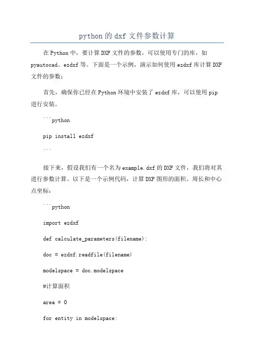
python的dxf文件参数计算在Python中,要计算DXF文件的参数,可以使用专门的库,如pyautocad、ezdxf等。
下面是一个示例,演示如何使用ezdxf库计算DXF 文件的参数:首先,确保你已经在Python环境中安装了ezdxf库,可以使用pip 进行安装。
```pythonpip install ezdxf```接下来,假设我们有一个名为example.dxf的DXF文件,我们将对其进行参数计算。
以下是一个示例代码,计算DXF图形的面积、周长和中心点坐标:```pythonimport ezdxfdef calculate_parameters(filename):doc = ezdxf.readfile(filename)modelspace = doc.modelspace#计算面积area = 0for entity in modelspace:if entity.dxftype( == 'LWPOLYLINE':area += entity.get_areaif entity.dxftype( == 'CIRCLE':area += entity.get_area#计算周长perimeter = 0for entity in modelspace:if entity.dxftype( == 'LWPOLYLINE':perimeter += entity.get_perimeterif entity.dxftype( == 'CIRCLE':perimeter += entity.get_perimeter#计算中心点坐标center_points = []for entity in modelspace:if entity.dxftype( == 'LWPOLYLINE':center_points.append(entity.get_centroid(.tuple() if entity.dxftype( == 'CIRCLE':center_points.append(entity.dxf.center)return area, perimeter, center_pointsarea, perimeter, center_points =calculate_parameters('example.dxf')print('面积:', area)print('周长:', perimeter)print('中心点坐标:', center_points)```以上代码中,我们首先使用ezdxf库的readfile方法读取DXF文件,并获取其模型空间。
HALCON算子一Classification1.1 Gaussian-Mixture-Models1.add_sample_class_gmm把一个训练样本添加到一个高斯混合模型的训练数据上。
2.classify_class_gmm通过一个高斯混合模型来计算一个特征向量的类。
3. clear_all_class_gmm清除所有高斯混合模型。
4. clear_class_gmm清除一个高斯混合模型。
5. clear_samples_class_gmm清除一个高斯混合模型的训练数据。
6. create_class_gmm为分类创建一个高斯混合模型。
7.evaluate_class_gmm通过一个高斯混合模型评价一个特征向量。
8. get_params_class_gmm返回一个高斯混合模型的参数。
9. get_prep_info_class_gmm计算一个高斯混合模型的预处理特征向量的信息内容。
10. get_sample_class_gmm从一个高斯混合模型的训练数据返回训练样本。
11. get_sample_num_class_gmm返回存储在一个高斯混合模型的训练数据中的训练样本的数量。
12. read_class_gmm从一个文件中读取一个高斯混合模型。
13. read_samples_class_gmm从一个文件中读取一个高斯混合模型的训练数据。
14. train_class_gmm训练一个高斯混合模型。
15. write_class_gmm向文件中写入一个高斯混合模型。
16. write_samples_class_gmm向文件中写入一个高斯混合模型的训练数据。
1.2 Hyperboxes1. clear_sampset释放一个数据集的内存。
2. close_all_class_box清除所有分类器。
3. close_class_box清除分类器。
4. create_class_box创建一个新的分类器。
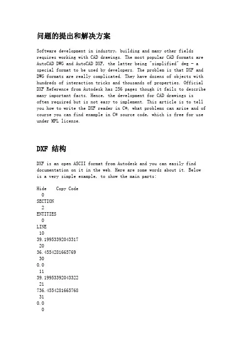
问题的提出和解决方案Software development in industry, building and many other fields requires working with CAD drawings. The most popular CAD formats are AutoCAD DWG and AutoCAD DXF, the latter being "simplified" dwg - a special format to be used by developers. The problem is that DXF and DWG formats are really complicated. They have dozens of objects with hundreds of interaction tricks and thousands of properties. Official DXF Reference from Autodesk has 256 pages though it fails to describe many important facts. Hence, the development for CAD drawings is often required but is not easy to implement. This article is to tell you how to write the DXF reader in C#, what problems can arise and of course you can find example in C# source code, which is free for use under MPL license.DXF 结构DXF is an open ASCII format from Autodesk and you can easily find documentation on it in the web. Here are some words about it. Below is a very simple example, to show the main parts:Hide Copy CodeSECTION2ENTITIESLINE1039.199533920433172036.4554281665769300.01139.1995339204332221736.4554281665768310.0ENDSECEOF0 - introduction of extended symbol names, following the "0"SECTION, ENDSEC - begin / end of section. Sections can include Header, Entities, Objects. In the above code, you see only Entities section where the entities are.LINE - begins LINE entity description. Lines:Hide Copy Code1039.19953392043317mean X1 double value. The value after 20 is Y1, after 30 - Z1 (0 in 2D drawings). 11, 21 and 31 codes are consequently for X2, Y2, Z2. So here we see the line with coordinates (39.19.., 36, 45.. - 39,19.., 736,45..) - this is vertical line.So our aim is to read this ASCII format. We need to load the file to stream and to take lines - even lines (0, 2, 4..) are CODE, odd lines (1, 3, 5...) are VALUE and repeat this procedure step by step till the end of file "EOF".Hide Shrink Copy Code// take a pair of lines in DXF file, repeat this till "EOF":public void Next(){FCode = Convert.ToInt32(FStream.ReadLine()); //codeFValue = FStream.ReadLine(); // value}// for code=0 we create entities. Entities here are not only those which visible in AutoCAD.// Entities can be also names of Sections and many other internal DXF objects.// This method is called for all FCode == 0public DXFEntity CreateEntity(){DXFEntity E;switch (FValue){case "ENDSEC":return null; // here we do not create entitycase "ENDBLK":return null;case "ENDTAB":return null;case "LINE": // for "LINE" value we create DXFLine objectE = new DXFLine();break;case "SECTION": // "SECTION" will be object to store other objects like LineE = new DXFSection();break;case "BLOCK": // create block objectE = new DXFBlock();break;case "INSERT": // insert is reference to block.E = new DXFInsert();break;case "TABLE":E = new DXFTable();break;case "CIRCLE":E = new DXFCircle();break;case "LAYER":E = new DXFLayer();break;case "TEXT":E = new DXFText();break;case "MTEXT":E = new DXFMText();break;case "ARC":E = new DXFArc();break;case "ELLIPSE":E = new DXFEllipse();break;default: // there are many other objects are possible. For them we create empty EntityE = new DXFEntity();break;}// each Entity will need reference to the Base object Converter, which stores all Entities.E.Converter = this;return E; // return Entity and after it is added to the array of Entities }The method to read properties of entities is essentially similar to the one described above but it has one important point: different entities have both identical and different properties. For instance, many Entities have "base point" - in DXF, which is described by codes: 10 (x), 20 (y), 30(z):Hide Copy CodeLINE1039.199533920433172036.4554281665769300.0These codes are the same for LINE, CIRCLE, ELLIPSE, TEXT and for many others. So we can make Object-Oriented structure to read and to store the properties in order to avoid double-coding. We will store Layer and Base Point in entity "DXFVisibleEntity" which will be ancestor for all visible entities. Look at the code to read these properties:Hide Shrink Copy Code//base class for all visible entitiespublic class DXFVisibleEntity : DXFEntity{//Base point (x, y, z) for all entitiespublic DXFImport.SFPoint Point1 = new SFPoint();// virtual function ReadProperty() is overridden in all descendants of Entity to read//specific propertiespublic override void ReadProperty(){// for the different codes we read valuesswitch (Converter.FCode){//read Layercase 8:layer = yerByName(Converter.FValue);break;//read Coordinatescase 10: //XPoint1.X = Convert.ToSingle(Converter.FValue, Converter.N);break;case 20: //YPoint1.Y = Convert.ToSingle(Converter.FValue, Converter.N);break;//read Colorcase 62:FColor = CADImage.IntToColor(Convert.ToInt32(Converter.FValue, Converter.N));break;}}}We use the same approach to read the second coordinate in LINE, radius in Circle and so on.DXF File and DXF Import .NET StructureThis scheme shows main parts of DXF file and the way they are connected with the C# source code in the project. The dash lines stand for associations between DXF file objects and objects, programmed in C#.CADImage is a class for loading from DXF file and drawing to Graphics. It stores the DXF Entities in field:Hide Copy Codepublic DXFSection FEntities;In the scheme, it is DXFSection.DXFEntity is base class for all Entities classes. Classes DXFBlocks and DXFSection are not visible. Class DXFVisibleEntity is the ancestor for all visible Entities.By the way, the scheme above is made in DXF format in ABViewer software. CAD TricksIf you are not familiar with AutoCAD, please pay attention to the structure of DXF entities. There is a special entity "Block" which may have many "inserts" in the CAD drawing. Block is just set of entities (including nested blocks) which can be inserted many times.NoteHide Copy CodeBlock changes many properties of element when showing it.So if you want to know the color of entity, it is not enough to read "Entity.Color" - it is necessary to see all the Inserts and Blocks, in which this entity can be included. To get the correct color in DXF Import .NET project we made the following function: EntColor(DXFEntity E, DXFInsert Ins).Please use EntColor() function get the correct Color type even if you do not have Blocks in the file. Pay attention that the most common color is "ByLayer" and in order to read the correct color, we need to read the color from Layer entity. This functionality is also provided in this function.Below is the EntColor function. It has many tricks, for instance checking the == "0" - in DXF layer "0" is special and elements with color "ByLayer" get the color from Block if they are on "0" layer.Hide Shrink Copy Code//Use this func to know the color of Entity, DXFInsert is Insert entity or null.public static Color EntColor(DXFEntity E, DXFInsert Ins){DXFInsert vIns = Ins;DXFEntity Ent = E;Color Result = DXFConst.clNone;if(Ent is DXFVisibleEntity) Result = E.FColor;/*if(Ent is Polyline)Result = ((Polyline)Ent).Pen.Pen.Color;*/if(yer == null) return Result;/* algorithm is rather difficult here. This is the way, how AutoCAD works with the colors,if you try to create entities in AutoCAD, you will see how they use Colors */if((Result == clByLayer)||(Result == clByBlock)){if((vIns == null)||((Result == clByLayer)&&( != "0"))){if(Result == clByLayer){if(yer.color != clNone)Result = yer.color;else Result = Color.Black;}}else{while(vIns != null){Result = vIns.color;if((Result != clByBlock) && !((Result == clByLayer) &&( == "0"))){if(Result == clByLayer)Result = yer.color;break;}if((vIns.owner == null)&&(Result == clByLayer))Result = yer.color;vIns = vIns.owner;}}}if((Result == clByLayer)||(Result == clByBlock))Result = clNone;return Result;}How to Use the SoftwareThe main code is in DXFImport.cs. You can just use this file in your project or see to it as an example of reading and visualization of DXF files. Sample code to use DXFImport.cs is Form1.cs.How to View EntitiesIn Form1.cs, we use the Form1_Paint event:Hide Copy Codeprivate void Form1_Paint(object sender,System.Windows.Forms.PaintEventArgs e){//FCADImage - base class to reference to DXFif (FCADImage == null)return;FCADImage.Draw(e.Graphics); // CADImage.Draw() accepts Graphics to draw to}We can use FCADImage.Draw() for drawing to any Graphics - for instance, to printer. FCADImage.Draw() function should use a special algorithm, when each entity is drawn with the use of block/insert/layer parameters.Hide Copy Codepublic void Draw(Graphics e){if (FMain == null)return;FGraphics = e;// Iterate begins to over the entities to draw all of themFEntities.Iterate(new CADEntityProc(DrawEntity), FParams);}Pay attention to FEntities.Iterate() func, it allows accessing all entities including their being inside the blocks. This is how it works: There is a class DXFGroup which is an ancestor of Entity and which can store array of Entities. For instance, Block is ancestor of DXFGroup and can store many entities like LINE. For better unification, we can use ONE BASE GROUP ENTITY object for all the drawing, this Entity will have array of all entities, each of them can also be the Group - the classic "Tree".Iterate method finally should call Draw() for each Entity in order to draw it to the Graphics:Hide Copy Codeprotected static void DrawEntity(DXFEntity Ent){Ent.Draw(FGraphics);}Draw() method is overridden in descendants of Entity to draw particular entities. Let us see in detail how it is implemented in DXFLine:Hide Copy Code// draw linepublic override void Draw(System.Drawing.Graphics G){// points P1 (x1, y1) and P2 (x2, y2) of LineSFPoint P1, P2;// read color via EntColor to get real colorColor RealColor = DXFConst.EntColor(this,Converter.FParams.Insert);// Read point 1 -convert global coordinates to the screen coordinates: P1 = Converter.GetPoint(Point1);//read point 2P2 = Converter.GetPoint(Point2);if (FVisible)G.DrawLine(new Pen(RealColor, 1), P1.X, P1.Y, P2.X, P2.Y);}1.We get the Real Color via DXFConst.EntColor(this,Converter.FParams.Insert); as I described before.2.Points are converted from Global Coordinates to screen coordinatesin function GetPoint(). GetPoint not only convertsglobal-to-screen but also uses Block offsets and block scale inside.Thus it facilitates the development work, eliminating the need to "see" what block is being drawn at the moment - Block changes"FParams.matrix" to draw itself. And all entities coordinates use this "FParams.matrix".3.Entity is drawn to the given Graphics G:So you can draw to printer, to raster image or to other Graphics. DXF Import .NET ReferenceHide Copy Codepublic class DXFConstStores constants and base functions.Hide Copy Codepublic class DXFMatrixClass to work with coordinates.Hide Copy Codepublic struct FRectDescription of 3D space where the CAD drawing is situated in global coordinates.Hide Copy Codepublic struct CADIterateStores all needed parameters for entities when processing "Iterate" function.Hide Copy Codepublic class CADImageClass to draw CAD drawing.Hide Copy Codepublic class DXFEntityBase class for all DXF Entities.Hide Copy Codepublic class DXFGroup : DXFEntityBase class for all group entities.Hide Copy Codepublic class DXFTable : DXFGroupClass to read from DXF "Table" section - here it reads only Layers.Hide Copy Codepublic class DXFVisibleEntity : DXFEntityBase class for all visible entities (invisible - are "DXFTable", "DXFLayer", etc.)Hide Copy Codepublic class DXFCustomVertex: DXFVisibleEntitySpecial class for 3D point in DXF.Hide Copy Codepublic class DXFText: DXFCustomVertexStores and Draws "Text" DXF entity.The following classes are for particular DXF entities:Hide Copy Codepublic class DXFLine : DXFVisibleEntitypublic class DXFArc: DXFCirclepublic class DXFEllipse: DXFArcpublic class DXFLayer: DXFEntityHide Copy Codepublic class DXFBlock : DXFGroupClass to work with DXF Block.Hide Copy Codepublic class DXFInsert : DXFVisibleEntityClass to work with "Insert" in DXF, for AutoCAD users this is "Block reference". Blocks are not visible, Inserts are visible.ConclusionThe purpose of the article is to give some advice how to write DXF readers. DXF file structure is not so difficult as its logical presentation. The article looks through the base DXF format problems and shows how to find solution for them. The example source is written in C# and may be helpful for all who need to have access to DXF files.。

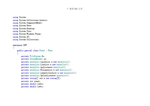
using System;using System.Collections.Generic;using ponentModel;using System.Data;using System.Drawing;using System.Text;using System.Windows.Forms;using System.IO;using System.Collections;namespace DXF{public partial class Form1 : Form{private FileStream fs;private StreamReader sr;private ArrayList LayerList = new ArrayList();private ArrayList LineList = new ArrayList();private ArrayList ArcList=new ArrayList();private ArrayList EllipseList = new ArrayList();private ArrayList LwopolylineList = new ArrayList();private ArrayList SplineList=new ArrayList();private string[] str = new string[2];private int count;private double leftx;private double lefty;private double rightx;private double righty;public Form1(){InitializeComponent();}private string[] ReadPair(){string code = sr.ReadLine().Trim();string codedata = sr.ReadLine().Trim();count += 2;string[] result = new string[2] { code, codedata };return result;}private void Read(){while (sr.Peek() != -1){str = ReadPair();if (str[1] == "SECTION"){str = ReadPair();switch (str[1]){case"HEADER": ReadHeader();break;case"TABLES": ReadTable();break;case"ENTITIES": ReadEntities();break;}}}sr.Close();fs.Close();btDraw.Enabled = true;label1.Text = count.ToString();count = 0;}private void ReadTable(){while (str[1] != "ENDSEC"){while (str[0] != "2" || str[1] != "LAYER") {str = ReadPair();}while (str[0] != "0" || str[1] != "LAYER") {str = ReadPair();}while (str[0] == "0" && str[1] == "LAYER") {ReadLAYER();}while (str[1] != "ENDSEC"){str = ReadPair();}}}private void ReadLAYER(){LAYER newlayer = new LAYER();while (str[1] != "ENDTAB"){str = ReadPair();switch (str[0]){case"2": = str[1];break;case"62": newlayer.colornum = str[1];break;case"6": newlayer.lstyle = str[1];break;case"370": newlayer.lwidth = str[1];break;}if (str[0] == "0" && str[1] == "LAYER") {LayerList.Add(newlayer);return;}}LayerList.Add(newlayer);}private void ReadEntities(){while (str[1] != "ENDSEC"){switch (str[1]){case"LINE": ReadLine();break;case"ARC": ReadArc();break;case"CIRCLE": ReadArc();break;case"ELLIPSE": ReadEllipse();break;case"LWPOLYLINE": ReadLwpolyline();break;case"SPLINE": ReadSpline();break;default: str = ReadPair();break;}}}private void ReadArc(){ARC newarc = new ARC();while (str[1] != "ENDSEC"){str = ReadPair();switch (str[0]){case"8": newarc.LName = str[1];break;case"10": newarc.CenterX = Double.Parse(str[1]);break;case"20": newarc.CenterY = Double.Parse(str[1]);break;case"40": newarc.Radiu = Double.Parse(str[1]);break;case"50": newarc.SAngle = Double.Parse(str[1]);break;case"51": newarc.EAngle = Double.Parse(str[1]);break;case"370": newarc.lwidth = str[1];break;case"0": ArcList.Add(newarc);return;}}}private void ReadLine(){LINE newline = new LINE();while (str[1] != "ENDSEC"){str = ReadPair();switch (str[0]){case"8": newline.LName = str[1];break;case"10": newline.StartX = Double.Parse(str[1]);break;case"20": newline.StartY = Double.Parse(str[1]);break;case"11": newline.EndX = Double.Parse(str[1]);break;case"21": newline.EndY = Double.Parse(str[1]);break;case"62": newline.colornum = str[1];break;case"370": newline.lwidth = str[1];break;case"0": LineList.Add(newline);return;}}}private void ReadEllipse(){ELLIPSE newellipse = new ELLIPSE();while (str[1] != "ENDSEC"){str = ReadPair();switch (str[0]){case"8": newellipse.LName = str[1];break;case"10": newellipse.CenterX = Double.Parse(str[1]);break;case"20": newellipse.CenterY = Double.Parse(str[1]);break;case"11": newellipse.DeltaX = Double.Parse(str[1]);break;case"21": newellipse.DeltaY = Double.Parse(str[1]);break;case"40": newellipse.Radio = Double.Parse(str[1]);break;case"41": newellipse.PSAngle = Double.Parse(str[1]);break;case"42": newellipse.PEAngle = Double.Parse(str[1]);break;case"370": newellipse.lwidth = str[1];break;case"0": EllipseList.Add(newellipse);return;}}}private void ReadLwpolyline(){LWPOLYLINE newlw = new LWPOLYLINE();while (str[1] != "ENDSEC"){str = ReadPair();switch (str[0]){case"8": newlw.LName = str[1];break;case"370": newlw.lwidth = str[1];break;case"62": newlw.colornum = str[1];break;case"90": newlw.PointCount = Int32.Parse(str[1]);break;case"70": newlw.Flag = Int32.Parse(str[1]);break;case"10": newlw.pointx = new double[newlw.PointCount];newlw.pointy = new double[newlw.PointCount];//if (newlw.Flag == 1)newlw.converxity = new double[newlw.PointCount];//else//newlw.converxity = new double[newlw.PointCount - 1]; newlw.pointx[0] = Double.Parse(str[1]);str=ReadPair();newlw.pointy[0] = Double.Parse(str[1]);for (int i = 1; i < newlw.PointCount; i++){string temp = sr.ReadLine().Trim();if (temp == "42"){newlw.converxity[i - 1] = Double.Parse(sr.ReadLine().Trim());i--;}else if (temp == "20"){string r = sr.ReadLine().Trim();newlw.pointy[i] = Double.Parse(r);}else{string r = sr.ReadLine().Trim();newlw.pointx[i] = Double.Parse(r);i--;}}string s = sr.ReadLine().Trim();if (s == "42")newlw.converxity[newlw.PointCount - 1] = Double.Parse(sr.ReadLine().Trim());else if (s == "0"){sr.ReadLine();LwopolylineList.Add(newlw);return;}else sr.ReadLine();break;case"0": LwopolylineList.Add(newlw);return;}}}public void ReadSpline(){SPLINE newspline = new SPLINE();while (str[1] != "ENDSEC"){str = ReadPair();switch (str[0]){case"8": newspline.LName = str[1];break;case"370": newspline.lwidth = str[1];break;case"62": newspline.colornum = str[1];break;case"70": newspline.Flag = Int32.Parse(str[1]);break;case"74": newspline.Count = Int32.Parse(str[1]);newspline.throughpx = new double[Int32.Parse(str[1])]; newspline.throughpy = new double[Int32.Parse(str[1])];break;case"12": newspline.SVertorX = Double.Parse(str[1]);break;case"22": newspline.SVertorY = Double.Parse(str[1]);break;case"13": newspline.EVertorX = Double.Parse(str[1]);break;case"23": newspline.EVertorY = Double.Parse(str[1]);break;case"11": newspline.throughpx[0] = Double.Parse(str[1]); str = ReadPair();newspline.throughpy[0] = Double.Parse(str[1]);str = ReadPair();for(int i=1;i<newspline.throughpx.Length;i++){str=ReadPair();if(str[0]=="11"){newspline.throughpx[i]=Double.Parse(str[1]);i--;}else if(str[0]=="21"){newspline.throughpy[i]=Double.Parse(str[1]); i--;}}if(newspline.Flag==11){for(int i=0;i<3;i++){str=ReadPair();}}break;case"0": SplineList.Add(newspline);return;}}}public void ReadHeader(){while (str[1] != "ENDSEC"){str = ReadPair();switch (str[1]){case"$EXTMIN": str = ReadPair();leftx = Double.Parse(str[1]);str = ReadPair();lefty = Double.Parse(str[1]);break;case"$EXTMAX": str = ReadPair();rightx = Double.Parse(str[1]);str = ReadPair();righty = Double.Parse(str[1]);break;}}}//打开DXF文件private void btOpen_Click(object sender, EventArgs e) {btDraw.Enabled = false;LayerList.Clear();LineList.Clear();ArcList.Clear();EllipseList.Clear();LwopolylineList.Clear();SplineList.Clear();this.openFileDialog1.ShowDialog();if (this.openFileDialog1.FileName.Trim() != "") {string path = this.openFileDialog1.FileName;fs = new FileStream(path, FileMode.Open, FileAccess.Read); sr = new StreamReader(fs);Read();}}private void btDraw_Click(object sender, EventArgs e){double width = Math.Ceiling(rightx) - Math.Ceiling(leftx) + 40;double height = Math.Ceiling(righty) - Math.Ceiling(lefty) + 40;Bitmap bmp = new Bitmap((int)width, (int)height);Graphics gx = Graphics.FromImage(bmp);double pw = width / (double)460;double ph = height / (double)384;for (int i = 0; i < LineList.Count; i++){LINE temp = (LINE)LineList[i];temp.Move(leftx, lefty, righty - lefty + 39);temp.Draw(gx);}for (int i = 0; i < ArcList.Count; i++){ARC temp = (ARC)ArcList[i];temp.Move(leftx, lefty, righty - lefty + 39);temp.Draw(gx);}for (int i = 0; i < EllipseList.Count; i++){ELLIPSE temp = (ELLIPSE)EllipseList[i];temp.Move(leftx + 1, lefty + 1);temp.Draw(gx, height - 1, pw, ph);}for (int i = 0; i < LwopolylineList.Count; i++){LWPOLYLINE temp = (LWPOLYLINE)LwopolylineList[i];temp.Draw(gx, leftx, lefty, righty - lefty + 39);}for (int i = 0; i < SplineList.Count; i++){SPLINE temp = (SPLINE)SplineList[i];temp.Draw(gx, leftx - 10, lefty, righty - lefty + 39); }this.pictureBox1.Image = bmp;}}}。
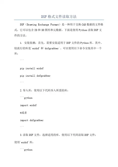
DXF格式文件读取方法DXF(Drawing Exchange Format)是一种用于交换CAD数据的文件格式,它可以包含2D和3D图形和元数据。
下面是使用Python读取DXF文件的方法。
1. 安装依赖:首先,需要安装适用于DXF文件的Python库。
其中,较流行的库是`ezdxf`和`dxfgrabber`。
可以使用以下命令安装其中一个库:```pip install ezdxfpip install dxfgrabber```2.导入库:使用以下代码导入所需的库:```pythonimport ezdxf#或者import dxfgrabber```3.读取DXF文件:选择适用的库,使用以下代码读取DXF文件:使用`ezdxf`库:```pythondoc = ezdxf.readfile('example.dxf')```使用`dxfgrabber`库:```pythondoc = dxfgrabber.readfile('example.dxf')```4.访问实体:接下来,可以通过以下方式访问DXF中的实体:使用`ezdxf`库:```pythonmsp = doc.modelspace( # 访问模型空间for entity in msp:if entity.dxftype( == 'LINE': # 仅处理类型为线的实体start = entity.dxf.start # 起点坐标end = entity.dxf.end # 终点坐标print(f"Line: {start}, {end}")elif entity.dxftype( == 'CIRCLE': # 处理圆center = entity.dxf.center # 圆心坐标radius = entity.dxf.radius # 半径print(f"Circle: {center}, {radius}")```使用`dxfgrabber`库:```pythonentities = doc.entitiesfor entity in entities:if entity.dxftype == 'LINE':start = entity.start # 起点坐标end = entity.end # 终点坐标print(f"Line: {start}, {end}")elif entity.dxftype == 'CIRCLE':center = entity.center # 圆心坐标radius = entity.radius # 半径print(f"Circle: {center}, {radius}")```以上代码遍历DXF文件中的所有实体,并打印出线段和圆的相关信息。
读取DXF格式文件的C++代码2008-08-15 07:49OpenGL是美国SGI公司最新推出的一套开放式的三维图形软件接口,适用于广泛的计算机环境,从个人计算机到工作站,OpenGL都能实现高性能的三维图形功能。
OpenGL本身不仅提供对简单图元的操作和控制,还提供了许多函数用于复杂物体的建模。
但是,我们通常喜欢使用AutoCAD和3DS及 3Dmax等工具来建立模型,并且我们已经有了很多这样的模型,那么我们如何才能资源共享,避免重复劳动呢?利用CAD图形标准数据交换格式—DXF格式,我们就能很容易地实现资源共享,而不需要重复建模。
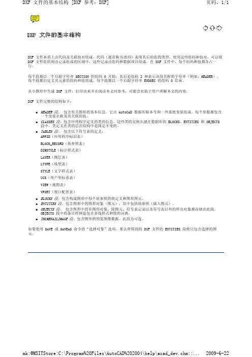
DXF文件的结构很清楚,具体如下:1. 标题段(HEADER )有关图形的一般信息都可以DXF 文件的这一节找到,每一个参数具有一个变量名和一个相关值。
2. 表段这一段包含的指定项的定义,它包括:a、线形表(LTYPE)b、层表(LYER)c、字体表(STYLE)d、视图表(VIEW)e、用户坐标系统表(UCS)f、视窗配置表(VPORT)g、标注字体表(DIMSTYLE)h、申请符号表(APPID)3. 块段(BLOCKS)这一段含有块定义实体,这些实体描述了图形中组成每个块的实体。
4. 实体段(ENTITIES )这一段含有实体,包括任何块的调用。
5. END OF FILE(文件结束)下面是对DXF的基本结构举一实例进行说明:0 0 后接SECTIONSECTION 表明这是一个段的开始2 2 后接的是段名HEADER 说明该段是HEADER 段(标题段)9$ACADVER 文件是由AUTOCAD 产生的1AC10089 9 后接 $UCSORG$UCSORG 用户坐标系原点在世界坐标系中的坐标10 10 对应 X0.0 X 的值20 20 对应 Y0.0 Y 的值30 30 对应 Z0.0 Z 的值9$UCSXDIR 这是一段不太相关的部分,略去101.0... ....9 9 后接 $EXTMIN$EXTMIN 说明三维实体模型在世界坐标系中的最小值10 10 对应 X-163.925293 X 的值20 20 对应 Y-18.5415860.0 Y 的值30 30 对应 Z78.350945 Z 的值9 9 后接 $EXTMAN$EXTMAX 说明三维实体模型在世界坐标系中的最大值10 10 对应 X202.492279 X 的值20 20 对应 Y112.634300 Y 的值30 30 对应 Z169.945602 Z 的值0 0 后接 ENDSECENDSEC 说明这一段结束了0 0 后接SECTIONSECTION 表明这是一个段的开始2 2 后接的是段名TABLES 说明该段是TABLES 段(表段)... ... ... ... 该段对我们不太相关,此处略去不进行说明0 0 后接 ENDSECENDSEC 说明这一段结束了0 0 后接SECTIONSECTION 表明这是一个段的开始2 2 后接的是段名ENTITIES 说明该段是ENTITIES 段(实体段)这是我0 们要详细说明的段,该段包含了所有实体的POLYLINE 点的坐标和组成面的点序。
gdal解析dxf块引用
使用GDAL库解析DXF文件中的块引用需要以下步骤:
1. 从DXF文件中读取块引用数据,可以使用Fiona库来读取DXF文件。
以下是使用Fiona库的示例代码:
```python
import fiona
with fiona.open("input.dxf", layer='Blocks') as src:
for feature in src:
block_ref = feature['geometry']
# 进一步处理块引用数据
```
2. 如果您需要使用GDAL库进行处理,则可以使用
`gdal.CreateGeometryFromWkb()`函数将块引用数据转换为GDAL几何对象。
以下是一个示例代码:
```python
import gdal
gdal_block_ref = gdal.CreateGeometryFromWkb(block_ref)
# 进一步处理GDAL几何对象
```
请注意,以上代码仅提供了处理DXF文件中块引用的基本框
架,具体的处理方法将取决于您的具体需求。
您可以根据需要进一步使用GDAL库的其他功能来解析和处理块引用数据。
python的dxf文件参数计算Python是一种开源的编程语言,具有广泛的应用场景,包括对图像、音频等各种类型文件的处理。
在Python中,我们可以使用一些库来处理DXF(Drawing Exchange Format)文件,并进行参数计算。
要处理DXF文件,我们可以使用一些第三方库,如pythoncad、ezdxf和dxfgrabber等。
这些库提供了一些方法和函数来读取和分析DXF文件,并提取所需的参数。
下面是一个使用dxfgrabber库来处理DXF文件并进行参数计算的示例:1. 安装dxfgrabber库:```bashpip install dxfgrabber```2.导入所需的库:```pythonimport dxfgrabber```3.读取DXF文件:```pythonfilename = "example.dxf" # 替换为你的DXF文件路径dxf = dxfgrabber.readfile(filename)```4.计算参数:根据具体需求,我们可以使用DXF文件中提供的实体对象来计算不同的参数,如长度、面积等。
-计算长度:```pythonlength = 0for entity in dxf.entities:if entity.dxftype == "LINE":length += entity.lengthprint("总长度:", length)```-计算面积:```pythonarea = 0for entity in dxf.entities:if entity.dxftype == "LWPOLYLINE":area += entity.areaprint("总面积:", area)```上面只是一个简单的示例,你可以根据具体的需求来进行更复杂的参数计算。
ezdxf库函数-回复什么是ezdxf库函数?ezdxf是一个用于创建和编辑DXF文件的Python库函数。
DXF是AutoCAD软件使用的文件格式,它允许用户在不同的CAD系统中共享和交换图形信息。
ezdxf库函数提供了一种简单和灵活的方式来处理DXF文件,使用户能够通过编程生成、修改和导出CAD图形。
如何安装ezdxf库函数?要安装ezdxf库函数,首先需要确保您的计算机已经安装了Python 解释器。
然后,您可以使用命令行工具或者在Python环境中使用pip命令来安装ezdxf库函数。
以下是安装步骤:步骤1:打开命令行工具或Python环境。
步骤2:运行以下命令来安装ezdxf库函数:pip install ezdxf这将自动从PyPI(Python包索引)下载并安装最新版本的ezdxf库函数。
接下来,您可以通过导入ezdxf库函数来验证安装是否成功。
在Python环境中输入以下代码:pythonimport ezdxf如果没有出现任何错误信息,表示ezdxf库函数已经成功安装并可供使用。
使用ezdxf库函数创建DXF文件要使用ezdxf库函数创建DXF文件,首先需要创建一个新的DXF文档对象。
然后,您可以通过向文档对象添加实体和图层来构建CAD图形。
以下是一些示例代码:pythonimport ezdxfdoc = ezdxf.new('R2000') 创建一个新的DXF文档对象msp = doc.modelspace() 获取模型空间添加直线实体msp.add_line((0, 0), (10, 0))添加圆实体msp.add_circle((5, 5), 2)创建新的图层layer = yers.new('MyLayer')将实体移到新的图层line = msp.query('LINE')[0]yer = 'MyLayer'保存DXF文件doc.saveas('drawing.dxf')以上代码示例创建了一个包含一条直线和一个圆的简单DXF图形,并将直线实体移动到一个新的名为“MyLayer”的图层中。
提取dxf图层数据另存(第一版)#include#include#include#includeusing std::string;using namespace std;int b[5]={0};int i=1;void Output1(FILE *fp1,FILE *fp2,char ch[80]) {char savelong[9999]={0};strcat(savelong,"$#");strcat(savelong,ch);char ss[80]={0};int c=1;for(int a=0;a<=1;){if(strcmp(ch,"AcDbEntity\n") == 0){a++;if(a!=2){fgets(ch,80,fp1);strcat(savelong,ch);if(strcmp(ch," 8\n") == 0){fgets(ch,80,fp1);strcat(savelong,ch);strcat(ss,ch);if(strcmp(ch,"0\n") == 0){cout<<ch;}else if(strcmp(ch,"GN-树木\n") == 0){cout<<ch;}else c--;}}else break;}else {if(strcmp(ch,"AcDbXrecord\n") == 0){a++;cout<<ch;break;}fgets(ch,80,fp1);strcat(savelong,ch);}}if(c!=0){fprintf(fp2,"%s",savelong);}if(c!=0){cout<<ss;}//fprintf(fp2,"%s","@");//fprintf(fp2,"%s",ss);}void readlayer(FILE *fp1,char ch[80],char name[99][80]){for(int a=0;a<1;){if(strcmp(ch," 2\n") == 0){fgets(ch,80,fp1);cout<<i<<".";strcpy(name[i],ch);cout<<name[i];//strcat(name[i],ch);i++;}fgets(ch,80,fp1);if(strcmp(ch," 0\n") == 0){break;}}}/*void savelayer(FILE *fp1,FILE *fp2,char ch[80],char load[80]) {char savelong[9999]={0};int c=0;strcat(savelong,ch);for(int a=0;a<1;){if(strcmp(ch,"AcDbSymbolTable\n") == 0){fgets(ch,80,fp1);strcat(savelong,ch);fgets(ch,80,fp1);strcat(save long," 2\n");c=1;}if(strcmp(ch," 2\n") == 0){fgets(ch,80,fp1);strcat(savelong,ch);if(strcmp(ch,load) == 0){c=1;}}fgets(ch,80,fp1);strcat(savelong,ch);if(strcmp(ch," 0\n") == 0){break;}}if(c!=0){fprintf(fp2,"%s",savelong);}}*///fprintf(fp2,"@");void read(char name[99][80]){FILE *fp1;//文件指针char ch[80];int a=0;fp1 = fopen("111111.dxf","r");//读取原始DXF文件if(fp1 == NULL){printf("Can not open this file1 !\n");return;}while( !feof( fp1 ) ){fgets(ch,80,fp1);if(strcmp(ch,"ENDSEC\n") == 0){a++;for(int a=0;a<6;a++) {fgets(ch,80,fp1);}}if(a==2){if(strcmp(ch,"LAYER\n") == 0){readlayer(fp1,ch,name);}}}fclose(fp1);}void save1(FILE *fp1,FILE *fp2,char ch[80],char load[80]) {char savelong[9999]={0};strcat(savelong,ch);//strcat(load,"\n");int c=0;for(int a=0;a<1;){if(strcmp(ch," 8\n") == 0){fgets(ch,80,fp1);strcat(savelong,ch);if(strcmp(ch,load) == 0){c=1;}}fgets(ch,80,fp1);strcat(savelong,ch);if(strcmp(ch," 0\n") == 0){break;}}if(c!=0){fprintf(fp2,"%s",savelong);}}void save(char load[80]){FILE *fp1,*fp2,*fp3;//文件指针char ch[80];char ENTITIES[50][80];int a=0,i=0,b;fp1 = fopen("111111.dxf","r");//读取原始DXF文件if(fp1 == NULL){printf("Can not open this file1 !\n");return;</name[i];</i<<".";</ss;}</ch;break;}</ch;}</ch;}}fp2 = fopen("acd2.dxf","w"); //修改后写入新的DXF文件if(fp2 == NULL){printf("Can not open this file2 !\n");return;}fp3 = fopen("ENTITIES.txt","r");//读取原始DXF文件if(fp3 == NULL){printf("Can not open this text !\n");return;}fgets(ch,80,fp3);while( !feof( fp3 ) ){fgets(ch,80,fp3); i++;strcpy(ENTITIES[i],ch);cout<<entities[i];}b=i;while( !feof( fp1 ) ){fgets(ch,80,fp1);if(strcmp(ch,"ENDSEC\n") == 0){a++;for(int a=0;a<6;a++) {fprintf(fp2,ch);fgets(ch,80,fp1);}}/*if(a==2){if(strcmp(ch,"LAYER\n") == 0){savelayer(fp1,fp2,ch,load);}else fprintf(fp2,ch);}*/if(a==4){ for(int b=0;b<=i;b++){if(strcmp(ch,ENTITIES[b]) == 0){save1(fp1,fp2,ch,load);}}}/*if(strcmp(ch,"LINE\n") == 0){save1(fp1,fp2,ch,load);}else if(strcmp(ch,"LWPOLYLINE\n") == 0){save1(fp1,fp2,ch,load);}else if(strcmp(ch,"TEXT\n") == 0){save1(fp1,fp2,ch,load);}else if(strcmp(ch,"HATCH\n") == 0){save1(fp1,fp2,ch,load);} else if(strcmp(ch,"POLYLINE\n") == 0){save1(fp1,fp2,ch,load);} else if(strcmp(ch,"VERTEX\n") == 0){save1(fp1,fp2,ch,load);} else if(strcmp(ch,"SEQEND\n") == 0){save1(fp1,fp2,ch,load);} else if(strcmp(ch,"INSERT\n") == 0){save1(fp1,fp2,ch,load);} else if(strcmp(ch,"POINT\n") == 0){save1(fp1,fp2,ch,load);}else if(strcmp(ch,"DIMENSION\n") == 0){save1(fp1,fp2,ch,load);}else if(strcmp(ch,"ARC\n") == 0){save1(fp1,fp2,ch,load);}else if(strcmp(ch,"CIRCLE\n") == 0){save1(fp1,fp2,ch,load);}else if(strcmp(ch,"MTEXT\n") == 0){save1(fp1,fp2,ch,load);}else if(strcmp(ch,"ELLIPSE\n") == 0){save1(fp1,fp2,ch,load);*/else fprintf(fp2,ch);}//fprintf(fp2,"0 \nENDSEC\n");//fprintf(fp2,"0 \nEOF");fclose(fp1);fclose(fp2);fclose(fp3);}void main(){char name[99][80];FILE *fp1,*fp2;//文件指针char ch[80];char load[80];int a;cout<<"现有图层:\n";read(name);cout<<"需要保存的图层:(编号)";cin>>a;strcpy(load,name[a]);cout<<name[a];save(load);system("pause");}</name[a];</entities[i];}。