英文 参考文献
- 格式:docx
- 大小:1.19 MB
- 文档页数:18
国外英文图书参考文献规范国外英文论文参考文献规范(国外英文论文参考文献格式)国外英文参考文献规范(国外英文参考文献格式)在处理英文参考文献时应尽量参考英语原版书的常用格式,以符合英语惯用法,使自己写的英语看起来像英美人写的英语。
下面是一些从英文原版书中摘出的例子。
例(1)—(7)选自英国Edinburgh University Press出版的Modern North American Criticism and Theory: A Critical Guide。
(1) Austin, J. L. How to do Things with Words. New York, 1962.(2) Bennett,A.(ed.)Readers and Reading. London, 1995.(3) —.Readings and Feelings.Urbana, IL, 1975.(4) —.Literature and Self-Awareness. New York, 1977.(5) Cook, P. and Bernink, M. (eds) The Cinema Book. London, 1999.(6) Derrida, J. Memoires: For Paul de Man, trans. Cecile Lindsay et al. New York, 1986.(7) Holland, N.‘Unity Identity Text Self’, in Reader-Response Criticism, ed. J.P. Tompkins. Baltimore, MD,1980.例(8)—(12)选自美国The Johns Hopkins University Press 出版的In Defense of American Higher Education。
(8) American Association of University Professors. 1966. Statement on government of colleges and universities. AAUP Bulletin 52, no. 4:375-79.(9) Barr, R., and J. Tagg. 1995. From teaching to learning: A new paradigm for undergraduate education. Change 27(November-December):12-25.(10) Benjamin, R. et al. 1993. The redesign of governance in higher education. Santa Monica, Calif.:RAND.(11) LaPidus, J. B. 1995. Doctoral education and studentcareer needs. In Student services for the changing graduate student population, edited by A.S. Pruitt-Logan and P. Isaac. San Francisco: Jossey-Bass.(12) ——.1997. Why pursuing a Ph.D. is a risky business. Chronicle of Higher Education, 14 November, A60.例(13)—(16)选自英国Sage Publications出版的Interviewing for Social Scientists。
英语论文参考文献精选3篇英语论文参考文献精选1篇英文及其它语种的文献在前,中文文献在后,参照以下标准执行。
期刊论文Bolinger, D. 1965. The atomization of word meaning [J]. Language 41 (4): 555-573.朱永生,2006,名词化、动词化与语法隐喻[J],《外语教学与研究》(2):83-90。
论文集论文Bybee, J. 1994. The grammaticization of zero: Asymmetries in tense and aspect systems [A]. In W. Pagliuca (ed.). Perspectives on Grammaticalization [C]. Amsterdam: John Benjamins. 235-254.文秋芳,2003a,英语学习者动机、观念、策略的变化规律与特点 [A]。
载文秋芳、王立非(编),《英语学习策略实证研究》[C]。
西安:陕西师范大学出版社。
255-259。
网上文献Jiang, Yan. 2000. The Tao of verbal communication: An Elementary textbook on pragmatics and discourse analysis [OL]. (accessed 30/04/2006).王岳川,2004,当代传媒中的网络文化与电视批评[OL], (2005年11月18日读取)。
专著Bloomfield, L. 1933. Language [M]. New York: Holt.吕叔湘、朱德熙,1952,《语法修辞讲话》[M]。
北京:中国青年出版社。
译著Nedjalkov, V. P. (ed.). 1983/1988. Typology of Resultative Constructions, trans. Bernard Comrie [C]. Amsterdam: John Benjamins.赵元任,1968/1980,《中国话的文法》(A Grammar of Spoken Chinese)[M],丁邦新译。
英文参考文献引用格式有两种:APA格式和MLA格式。
1、APA格式:APA(American Psychological Association)是一种标明参考来源的格式,主要使用在社会科学领域及其他学术准则中,国内很多期刊也是采用的APA格式。
APA文内注的参考文献格式是:“(作者姓氏,发表年份)”。
APA文末的参考文献目录格式是:Reference List, 必须以姓(Family name)的字母顺序来排列,基本结构为:期刊类:【作者】【发表年份】【文章名】【期刊名】【卷号/期数:起止页码】Smith,J.(2006).The title of the article.The title of Journal,1,101-105。
非期刊类:【作者】【发表年份】【书籍名】【出版地:出版社】Sussan.G.(2002).What computers can't do.New York:Harp&Row。
2、MLA格式:MLA是美国现代语言协会(Modern Language Association)制定的论文指导格式,多用于人文学科(Liberal Arts)。
MLA文内注的基本格式:“(作者姓氏,文献页码)”。
MLA文末的参考文献目录格式:在MLA格式中称为Works Cited,同样是以姓(Family name)的字母顺序来排列,基本结构为:期刊类:【作者】【“文章名”】【期刊名】【卷号或期数】【发表年份】起止页码】Nwezeh,C.E.“The Comparative Approachto Modern African Literature.”Year book of General and Comparative Literature28(1979):22。
非期刊类:【作者】【书籍名】【出版地:出版社】【发表年份】Winfield,Richard w in Civil Society.Madison:U of Wisconsin P,1995。

英文引用及参考文献格式要求一、参考文献的类型参考文献即引文出处的类型以单字母方式标识,具体如下:M——专着C——论文集N——报纸文章J——期刊文章D——学位论文R——报告对于不属于上述的文献类型,采用字母“Z”标识;对于英文参考文献,还应注意以下两点:①作者姓名采用“姓在前名在后”原则,具体格式是:姓,名字的首字母.如:MalcolmRichardCowley应为:Cowley,M.R.,如果有两位作者,第一位作者方式不变,&之后第二位作者名字的首字母放在前面,姓放在后面,如:FrankNorris与IrvingGordon应为:Norris,F.&I.Gordon.;②书名、报刊名使用斜体字,如:MasteringEnglishLiterature,EnglishWeekly;二、参考文献的格式及举例1.期刊类格式序号作者.篇名J.刊名,出版年份,卷号期号:起止页码.举例1王海粟.浅议会计信息披露模式J.财政研究,2004,211:56-58.2夏鲁惠.高等学校毕业论文教学情况调研报告J.高等理科教育,20041:46-52.3Heider,E.R2.专着类格式序号作者.书名M.出版地:出版社,出版年份:起止页码.举例4葛家澍,林志军.现代西方财务会计理论M.厦门:厦门大学出版社,2001:42.5Gill,R.MasteringEnglishLiteratureM.London:Macmillan,1985:42-45.3.报纸类格式序号作者.篇名N.报纸名,出版日期版次.举例6李大伦.经济全球化的重要性N.光明日报,1998-12-273.7French,W.BetweenSilences:AVoicefromChinaN.AtlanticWeekly,19871533.4.论文集格式序号作者.篇名C.出版地:出版者,出版年份:起始页码.举例8伍蠡甫.西方文论选C.上海:上海译文出版社,1979:12-17.9Spivak,G.“CantheSubalternSpeak”A.InC.Nelson&L.Grossbergeds..Vi ctoryinLimbo:ImigismC.Urbana:UniversityofIllinoisPress,1988,pp.271-31 3.。
1.Alonso, W. ,1964, Location and Land Use, Harvard University Press.2.Amin, A. & Tomaney, J. ,1995, Behind the Myth of the European Union¡GProspects for Cohesion. London¡G Routledge.3.Begg, I., 1999, Cities and Competitiveness, Urban Studies, 36¡]5-6¡^,pp.795-809.4.Begg, I. G. & Cameron, G. C. ,1988, High Technology location and urban areasof Great Britain, Urban Studies, 25, pp.361-379.5.Blakely, E.J. ,1994, Planning Local Economic Development¡G Theory andPractice, 2nd edn. California Sage.6.Bramezza I., 1996, The Competitiveness of the European City and the role ofUrban Management in Improving the City’s Performance.7.Bruinsma, F. & Rietveld, P. ,1993, Urban Agglomeration in EuropeanInfrastructure Networks , Urban Studies , 30, pp.919-934.8.Castells, M., 1989, The Imformation City. Oxford¡G Blackwell.9.Castells, M. & Hall, A. , 1994, Technopoles of the World. London¡G Routledge.10.Chisholm, M. D. I. ,1995, Britain on the Edge of Europe. London¡G Routledge.11.Coombes, M. & Wong, C. ,1994, Methodological Steps in the Development ofMultivariate Index for Urban Regional Policy Analysis, Environment andPlanning A, 26.12.Deas, I. & Giordano, B., 2001,Urban Competitiveness in major English Cities,Environment and Planning A., 33,pp.1411-1429.13.Debbage, K. & Rees, J. ,1991, Company Perceptions of Comparativeadvantage by Region, Regional Studies, 25, pp.199-206.14.Dimond , D.& Spence’s, N. A. ,1989, Infrastructure and Industrial Cost inBritish Industry. Londo¡G HMSO.15.El-Agraa, A. M., 1997, UK COMPETITIVENESS POLICY vs. JAPANESEINDUSTRIAL POLICY, The Economic Journal, 107, pp.1504-1517.16.European Commission ,1994, Competitiveness and Cohesion¡G Trends in theRegions .Fifth Periodic Report on the Social and Economic Situation andDevelopment of the Regions in the Community .Luxembourg¡G Office ofOfficial Publications of the European Commission.17.Freeman et al. , 1982, Unemployment and Technical Innovation , A Study of aLong Waves and Economic Development. France Printer, London.18.Freeman, C. & Parez, C., 1988, Structural crisis of ad justment , businesscycles and investment behavior, Technical Change and Economic Theory ,pp.38-66.19.Frenke, A., 2000, Can Regional Policy Affect Firms, Innovation Potential inLagging Regions, Regional Science, 34,pp.315-341.20.Hall, P. et al., 1987, Western Sunrise¡G The Genesis and Growth of Britain’sMajor High Tech Corridor. Hemel Hempstead¡G Allan and Unwin.21.Hatfield, L., 2002, Performance Effect of Alternative Joint Venture ResourceResponsibility Structures , Journal of Business Venturing ,17, pp.343-364. 22.Herrschel, T., 1995, Local Policy Restructuring¡G A Comparative Assessment ofPolicy Responses in England and Germany, Area, 27, pp.228-241.23.HM. Government, 1993, Competitiveness Helping Business to Win. London¡GHMSO.24.Howells, J. & Green, A. ,1988, Technological Innovations, Structural Changeand Location in UK Services. Aldershot¡G Avebury.25.IMD., 2002, The World Competitiveness Yearbook.26.James, S., 2002, Knowledge Spillovers and Reasons for the Concentration ofInnovation SMEs. , Urban Studies, 39¡q5-6¡r,pp.885-902.27.John, R.B.,1997,Small and Medium-sized Enterprises , Business Link andNew Knowledge Workers, Policy Studies, 18¡]1¡^,pp.67-80.28.Kerlinger, F. N., 1986, Foundations of Behavioral Research, Harcourt BraceJovanovich Publishing, 1986.29.Kresl, K. P. & Singh, B., 1999, Competitiveness and Urban Economy, UrbanStudies ,36¡]5-6¡^,pp.791-793.30.Krugman, P., 1991a, Increasing Returns and Economic Geography , Journal ofPolitical Economy, 99, pp.483-499.31.Krugman, P., 1991b, The Geography of Trade. Cambridge, Ma¡G MIT Press.ll, S.,2001, Competitiveness Indices and Developing Countries ¡G AnEconomic Evaluation of the Global Competitiveness Report”, WorldDevelopment, 29¡q9¡r, pp.1501-1525.33.Malecki, E. J., 2002 ,Hard and Soft Networks for Urban Competitiveness,Urban Studies,39¡]5-6¡^,pp.929-945.34.Marshall, J. N. & Alderman, N. & Thwaites, A.T. ,1992,Civil ServicesRelocation and the English Regions , Regional Studies ,25, pp.499-510.35.Massey, D. ,1995, The Spatial Division of Labor¡G Social Structures andGeography of Production. London¡G Macmillan.36.Nijkamp, P. ,1986, Infrastructure and regional development¡G amultidimensional policy analysis , Empirical Economics , 11 , pp.1-21.anization for Economic Cooperation and Development , OECD .,1997,TheOECD List of Social Indicators¡A The OECD Social Indicator DevelopmentProgram , 538.Oughton, C., COMPETITIVENESS POLICY IN THE 1990s , The EconomicJournal, 107,pp.1486-1503.39.Porter, M.E.,2000,Location, Competition, and Economic Development:Local Cluster in a Global Economy, Economic DevelopmentQuarterly,14,pp.15-34.40.Pyke, F. & Sengenberger, W., 1992, Industrial District and Local EconomicRegeration. Geneva¡G International Institute for Labor Studies.41.Rapkin, D. & Strand, D., 1995, Competitiveness¡G useful concept , politicalslogan or dangerous obsession, in National Competitiveness in a GlobalEconomy Eds. D. Rapkin, W. Avery¡qLynne Rienner, London¡r,pp.1-30. 42.Schumpeter, J. A. ,1934, The Theory of Economic Development ,trans. by R.Opie. Cambridge , Ma¡G Harvard Universuty Press.43.Steiner ,1990, ‘Good’ and ‘Bad’ Regions¡H Criteria to Evaluate RegionalPerformance in face of an enforced internationlisation on the Europeaneconomy, Build Environment, 16(1), pp.52-68.44.Sylwester, S.,2001 ,R&D and Economic Growth, Knowledge, Technology, &Policy, 13¡q4¡r,pp.71-84.45.Tainer E.M., 1998,”Using Economic Indicators to Improve InvestmentAnalysis”.46.Taylor , J. ,1993, An Analysis of the Factors Determining the Geographicaldistribution of Japanese manufacturing Investment in the UK 1984-1991,Urban Studies , 30, pp.1209-1224.47.Townroe, P. ,1976, Planning Industrial Location . London¡G Leonard Hill Books.48.Wong, C., 2002,“Developing Indicators to Inform Local EconomicDevelopment in England”, Urban Studies , 39¡]10¡^, pp.1833-1863.49.World Economic Forum¡]WEF¡^,2002, Global Competitiveness Report50.¤ý½r·O¡A2001¡A³Ð·sªºªÅ¶¡¡Ð¥ø·~¶°¸s»P°Ï°ìµo®i¡C51. ¥@¬ÉÄvª§¤O¦~³ø¡A2000¡A·ç¤h¬¥®á°ê»ÚºÞ²z¾Ç°|IMD¡C52. ¥ª®m¼w¡B¤×±Ó§g¡A2001¡A°ê®a¬ì§ÞÄvª§¤O«ü¼Ð¤§¬ã¨s¡A¥xÆW¸gÀÙ¬ã¨s°|¡C53. ¦¶¶³ÄP¡AªL¬ü¸©¡A2001¡A±q WEF¥þ²yÄvª§¤O³ø§i¬Ý¥xÆW¤§Ävª§¤O¡C54. ¬IÂE§Ó¡A2000¡A¦a°ÏÄvª§¤O«ü¼ÐÅé¨t«Øºc¤§¬ã¨s¡A¦æ¬F°|°ê®a¬ì¾Ç©e-û·|55. §dÀٵءA1994¡A¥_°ª¨â¥«ª§¿ì¨È¹B¨Æ«áªº¬Ù«ä¡X´Á«Ý³£¥««Ø¥ß¨}µ½ªºÄvª§¾÷¨î¡A°ê®a¬Fµ¦Âù¤ë¥Z¡A²Ä88´Á¡A-¶14-15¡C56. ©P¤å½å¡A1997¡A¦hÅܶq²Î-p¤ÀªR¡C57. ©ó¥®µØ¡B±i¯q¸Û¡A2000¡A¥ÃÄòµo®i«ü¼Ð¡A°ê¥ß¥xÆW¤j¾ÇÀô¹Ò¤uµ{¾Ç¬ã¨s©Ò¡C58. §Å-Z¿K¡A2002¡A°Ï°ì³Ð·s¨t²ÎÆ[ÂI¤U¤¤¥xÆWºë±K¾÷±ñ²£·~³Ð·s¤§¬ã¨s¡AªF®ü¤j¾Ç¤u·~¤uµ{¾Ç¨tºÓ¤h½×¤å¡C59. ©ÐµL¬È¡B¤ý¨qªv¡A2001¡A²£·~Ävª§¤O½×¡A¤W®ü¸gÀÙ¡A-¶27-31¡C60. ªL¨Î¾ì¡A2002¡A¨|¦¨¤¤¤ß¼vÅT¼t°Ó³Ð·s¬¡°Ê¦¨®Ä¤§¬ã¨s¡A¥xÆW¤j¾Ç«Ø¿v»P«°¶m¬ã¨s©ÒºÓ¤h½×¤å¡C61. «J§B·ì¡A2001¡A³£¥«¸gÀçºÞ²zÁZ®Äµû¶q¨t²Î¤§¬ã¨s¡A°ê¥ß¦¨¥\¤j¾Ç³£¥«-p¹º¾Ç¨tºÓ¤h½×¤å62. ®}¼zªâ¡A1999¡A¥HÆp¥Û¼Ò¦¡«Ø¥ß°ê»Ú´ä¤fÄvª§¤Oµû¦ô·Ç«h¤§¬ã¨s¡A¥æ³q¤j¾Ç¹B¿é»PºÞ²z¾Ç¨tºÓ¤h½×¤å¡C63. ³¯°¶§Ó¡A1994¡A¥i¤Î©Ê»P°Ï°ìµo®i¢w¥H¥xÆW¦a°Ï¦è³¡¹B¿é¨«´Y¬°¨Ò¡A¤¤¿³¤j¾Ç³£¥«-pµe¬ã¨s©ÒºÓ¤h½×¤å¡C64. ³¯¥¿¨k¡BÃÓ¤j¯Â¡A1998¡A°ê®aÄvª§¤O¡B²£·~Ävª§¤O»P¼t°ÓÁZ®Ä-¨Ì¾Ú¥@¬ÉÄvª§¤O³ø¾É»P PorterÆp¥Û¼Ò¦¡¬°°ò¦¤§¹êÃÒ¬ã¨s¡A¥ø·~ºÞ²z¾Ç³ø¡A43´Á¡A -¶73-106¡C65. ³¯«a¦ì¡A2001¡A«°¥«Ävª§Àu¶Õµû¶q¨t²Î¤§¬ã¨s¡A°ê¥ß¦¨¥\¤j¾Ç¼Æ-p¹º¬ã¨s©Ò³Õ¤h½×¤å¡C66. ³¯¾åÁn¡A2001¡A²£·~Ävª§¤Oªº´ú«×»Pµû¦ô¡A¤W®ü¸gÀÙ¡A-¶45-47¡C67. ³¯Äפå¡A2000¡A¥xÆW¦a°Ï°]¬F¤£§¡»P°Ï°ìµo®i¤§¬ã¨s¡A¥x¥_¤j¾Ç°]¬F¾Ç¨tºÓ¤h¯ZºÓ¤h¾Ç¦ì½×¤å¡C68. ±i¥@¾±¡A2002¡A¦a²z¸s»E¤º¼t°Ó¤§ºôµ¸Ãö«Y¹ï¨äÄvª§¤O¼vÅT¤§¬ã¨s¡Ð·s¦Ë¬ì¾Ç¶é°Ï¤§¹êÃÒ¡A´Â¶§¬ì§Þ¤j¾Ç¥ø·~ºÞ²z¨tºÓ¤h½×¤å¡C³\®Ñ»Ê¡A2000¡A²£·~°ê»ÚÄvª§¤O¤§µo®i¤Î¼vÅT¦]¯À¤ÀªR¡X°ê®aÄvª§¤OÆ[ÂI¡A°ê¥ß¥xÆW¤j¾Ç°Ó¾Ç¬ã¨s©Ò³Õ¤h¾Ç¦ì½×¤å¡C70. ¶À¤åÄå¡A2000¡A³£¥«Ävª§¤O»P»s³y·~¥Í²£¤OÃö«Y¤§¬ã¨s¡A°ê¥ß¬Fªv¤j¾Ç¦a¬F¾Ç¨tºÓ¤h¯ZºÓ¤h¾Ç¦ì½×¤å¡C71. ¶V¾¤©ú¡B§N?©ú¡A2002¡A«°¥«³Ð·s¨t²Î¡C72. ¸â¼wªQ¡A1997¡A¸gÀÙ²Î-p«ü¼Ð--Ý-z¬F©²²Î-p¹ê°È¡AµØ®õ¤å¤Æ¨Æ·~¦³--¤½¥q¡C73. ·¨¬FÀs¡A2001¡A§Þ³N³]¬IªÅ¶¡¤À§G¹ï³Ð·s¦¨®Ä¼vÅT¤§¬ã¨s¡Ð¥H¥xÆW»s³y·~¬°¨Ò¡A¥x¥_¤j¾Ç³£¥«-pµe¬ã¨s©ÒºÓ¤h½×¤å¡C74. ¾H´]¤å¡A2001¡A¥xÆW¦a°Ï¦a¤èÄvª§¤Oµû¦ô«ü¼Ð«Øºc¤§¬ã¨s¡A»²¤¯¤j¾ÇÀ³¥Î²Î-p¾Ç¬ã¨s©ÒºÓ¤h½×¤å¡C75. Á¨¹©÷¡A2000¡A¥«³õ½Õ¬d»P¤ÀªR§Þ³N¡C76. Áú·ÇªL¡A2001¡A´£ª@²£·~Ävª§¤Oªº¼Ð·Ç¡A¤W®ü¸gÀÙ¡A-¶48-49¡C。

毕业论文英文参考文献论文的参考文献是在英语专业论文写作过程中,对某一著作或论文的整体的参考或借鉴。
征引过的文献在注释中已注明,不再出现于文后参考文献中。
下面是店铺带来的关于毕业论文英文参考文献的内容,欢迎阅读参考!毕业论文英文参考文献(一)[1]徐安律.原住民小说《圆屋》获美国国家图书奖[N].中华读书报,2012(004).[2]Coulombe,JosephL.ReadingNativeAmericanLiterature[M\. NewYork:Routledge,2011.[3]Erdrich,Louise.TheRoundHouse\M\.NewYork:HarperCollin sPublishers,2012.[J].作家,2013(12):1.[4]杨恒.弱者的失语法律的缺位--评美国国家图书奖获奖作品《圆屋》[J].博览群书,2013(6):84-88.[5]Said,Edward.CultureandImprerialism[M].NewYork:Vintage Books,1994.[6]Erdrich,Louise.LoveMedicine[M],NewYork:HarperPerennia l,1993.[7]罗世平.凝视:后殖民主义文学折射[J].国外文学,2006(4):122.[8]任一鸣.《后殖民:批评理论与文学》[M].北京:外语教学与研究出版社,2008.[9]Halliday,Lisa.LouiseErdrich[J].ParisReview,2010(52):133-137.[10]温语晴.书写印第安文化的温暖和困境一美国当代作家路易丝·厄德里克和她的作品.[11]陈榕.《凝视》[A].《西方文论关键词》[C].ed.赵一凡.北京:外语教学与研究出版社,2011.[12]Russo,Maria.Disturbing the spirits[i]. New York TimesBook Review, 2012(10): 9[13]Said, Edward. Culture and Imprerialism[M]. New York: Vintage Books,1994.[14]Fanon,Frantz. The Wretched of the Earth[M]. New York: Grove Press,1968.[15]徐安律.原住民小说《圆屋》获美国国家图书奖[N].中华读书报,2012(004).毕业论文英文参考文献(二)[1] 陈鹏.高速公路服务区及收费站建筑节能研究[D].中南大学,2007[2] 清华大学建筑节能研究中心.中国建筑节能年度发展研究报告[M]2014.北京:中国建筑工业出版社,2014:39[3] 李慧玲.绿色建筑理念下的高速公路服务区建筑设计研究[D].西安:长安大学,2011[4] 公通字[2009]46 号.民用建筑外保温系统及外墙装饰防火暂行规定[S].新乡市建筑工程质量监督站印发.2009[5] 汤旭东.建筑工程中的现浇聚苯复合材料屋面保温技术[J].江西建材,2014,(11):45[6] 杨欣霖.高速公路服务区绿色建筑技术体系研究[D].西安:长安大学,2011[7] 欧志华,郭俊明.浅谈我国建筑节能50%设计标准的含义[J].建筑节能,2007,35(12):60-62[8] 邹惠芬,王国业,郭立杰等.严寒地区窗户热工性能对建筑能耗的影响分析[J].沈阳建筑大学学报(自然科学版).2009,25(5):982-986[9] 崔洪军,刘孔杰.国外服务区建设及研究现状[J].中国交通报,2008,(12):138-139[10] 郎松军.建筑结露的起因和防治方法初探[J].四川建筑,2002,22(Z1):201-203[11] 王金奎,史慧芳,邵旭.体形系数在公共建筑节能设计中的应用[J].低温建筑技术,2010,(5):98-99[12] 王丽颖,丘雨佳.对德国被动式居住建筑节能技术的考察[J].长春工程学院学报,2013,14(3):38-40[13] 赖有志,陆京海,杨军霞,张童.现浇轻质泡沫混凝土在屋面工程中的应用[J].施工技术.2011,40(14):79-94毕业论文英文参考文献(三)[1]蒋花,史志康.整合与对话一论《金色笔记》中的戏仿[J].当代外国文学,2007(2):78.[2]黄梅.女人的危机和小说的危机--女人与小说杂谈之四[J].读书,1988(01):5.[3]孙宗白.真诚的女作家多丽丝·莱辛[J].外国文学研宄,1981(3):70.[4]施旻.《金色笔记》是女性主义文本吗·一关于多丽丝·莱辛及其《金色笔记》的论争[J].东岳论丛,2000(5): 132-134.[5]李福祥.多丽丝·莱辛笔下的政治与妇女主题[J].外国文学评论,1993(4):40-43[6]黎会华·多丽丝·莱辛《金色笔记》中的现代主义技巧分析[J].外语研究,2003(6):73.[7]陈才宇,刘新民.金色笔记[M].北京:译林出版社,2000.[8]黎会华·解构菲勒斯中心:构建新型女性主义主体一《金色笔记》的女性主义阅读[J].浙江师范大学学报,2004(3):33.[9]韩小敏,纪卫宁.析伍尔夫与莱辛文学创作的相似性[J].理论专刊,2004(8):125-126.[10]姜红.有意味的形式[J].外国文学,2003(4):96-98.[11]徐燕.《金色笔记》的超小说艺术[J].宁波大学学报,2003(3):78-80[12]蒋花,史志康.整合与对话一论《金色笔记》中的戏仿[J].当代外国文学,2007(2):78.[13]卢婧.《金色笔记》的艺术形式与作者莱辛的人生体验[D].南京师范大学博士学位论文,2008.[14]佘海若.迟来的正义:被缚的自由女性一记2007年诺贝尔文学奖[J].今日科苑,2007(23): 19-24.[15]刘颖.建构女性的主体性话语一评多丽丝·莱辛的《金色笔记》[J].邵阳学院学报,2004(4).[16]范晓红.从《金色笔记》解读多丽丝·莱辛的生态整体观[D].南京师范大学,2011.[17]Brewster, Dorothy. Doris Lessing\M\. New York: Wayne, 1965: 161.[18]Spilka, Mark. Lessing and Lawrence: the Battle of theContemporary Literature,1975(16): 218-240.。

英文参考文献标准格式英文参考文献标准格式一、参考文献的类型参考文献(即引文出处)的类型以单字母方式标识,具体如下:--专著,著作[C]--论文集(一般指会议发表的论文续集,及一些专题论文集,如《***大学研究生学术论文集》[N]-- 报纸文章[J]--期刊文章:发表在期刊上的论文,尽管有时我们看到的是从网上下载的(如知网),但它也是发表在期刊上的,你看到的电子期刊仅是其电子版[D]--学位论文:不区分硕士还是博士论文--报告:一般在标题中会有”关于****的报告”字样[S]-- 标准[P]--专利[A]--文章:很少用,主要是不属于以上类型的文章[Z]--对于不属于上述的文献类型,可用字母”Z”标识,但这种情况非常少见常用的电子文献及载体类型标识:[DB/OL] --联机网上数据(database online)[DB/MT] --磁带数据库(database on magnetic tape)[M/CD] --光盘图书(monograph on CDROM)[CP/DK] --磁盘软件(computer program on disk)[J/OL] --网上期刊(serial online)[EB/OL] --网上电子公告(electronic bulletin board online)很显然,标识的就是该资源的英文缩写,/前面表示类型,/后面表示资源的载体,如OL表示在线资源二、参考文献的格式及举例1.期刊类【格式】[序号]作者.篇名[J].刊名,出版年份,卷号(期号)起止页码.【举例】[1] 周融,任志国,杨尚雷,厉星星.对新形势下毕业设计管理工作的思考与实践[J].电气电子教学学报,2003(6):107-109.[2] 夏鲁惠.高等学校毕业设计(论文)教学情况调研报告[J].高等理科教育,2004(1):46-52.[3] Heider, E.R.& D.C.Oliver. The structure of color space in naming and memory of two languages [J]. Foreign Language Teaching and Research, 1999, (3): 62 67.2.专著类【格式】[序号]作者.书名.出版地:出版社,出版年份:起止页码.【举例】[4] 刘国钧,王连成.图书馆史研究.北京:高等教育出版社,1979:15-18,31.[5] Gill, R. Mastering English Literature . London: Macmillan, 1985: 42-45.3.报纸类【格式】[序号]作者.篇名[N].报纸名,出版日期(版次).【举例】[6] 李大伦.经济全球化的重要性[N]. 光明日报,1998-12-27(3).[7] French, W. Between Silences: A V oice from China[N]. Atlantic Weekly, 1987-8-15(33).4.论文集【格式】[序号]作者.篇名[C].出版地:出版者,出版年份:起始页码.【举例】[8] 伍蠡甫.西方文论选[C]. 上海:上海译文出版社,1979:12-17.[9] Spivak,G. “Can the Subaltern Speak?”[A]. In C.Nelson & L. Grossberg(eds.). Victory in Limbo: Imigism [C]. Urbana: University of Illinois Press, 1988, pp.271-313.[10] Almarza, G.G. Student foreign language teacher's knowledge growth [A]. InD.Freeman and J.C.Richards (eds.). Teacher Learning in Language Teaching [C]. New York: Cambridge University Press. 1996. pp.50-78.5.学位论文【格式】[序号]作者.篇名[D].出版地:保存者,出版年份:起始页码.【举例】[11] 张筑生.微分半动力系统的不变集[D].北京:北京大学数学系数学研究所, 1983:1-7.6.研究报告【格式】[序号]作者. 篇名.出版地:出版者,出版年份:起始页码.【举例】[12] 冯西桥.核反应堆压力管道与压力容器的LBB分析.北京:清华大学核能技术设计研究院, 1997:9-10.7.专利【格式】[序号]专利所有者.题名[P].国别:专利号,发布日期.【举例】[13] 姜锡洲.一种温热外敷药制备方案[P].中国专利:881056073, 1989 07 26.8.标准【格式】[序号]标准编号,标准名称[S].【举例】[14] GB/T 16159-1996, 汉语拼音正词法基本规则[S].9.条例【格式】[序号]颁布单位.条例名称.发布日期【举例】[15] 中华人民共和国科学技术委员会.科学技术期刊管理办法[Z].1991-06-0510.电子文献【格式】[序号]主要责任者.电子文献题名.电子文献出处[电子文献及载体类型标识].或可获得地址,发表或更新日期/引用日期.【举例】[16] 王明亮.关于中国学术期刊标准化数据库系统工程的进展[EB/OL].http: ///pub/wml.txt/980810 2.html, 1998 08 16/1998 10 04.[17] 万锦.中国大学学报论文文摘(1983 1993).英文版[DB/CD]. 北京: 中国大百科全书出版社, 1996.11.各种未定义类型的文献【格式】[序号] 主要责任者.文献题名[Z].出版地:出版者, 出版年.特别说明:凡出现在”参考文献”项中的标点符号都失去了其原有意义,且其中所有标点必须是半角,如果你的输入法中有半角/全解转换,则换到半角状态就可以了,如果你的输入法中没有这一转换功能,直接关闭中文输入法,在英文输入状态下输入即可.其实,很多输入法(如目前比较流行的搜狐输入法)都提供了四种组合:(1)中文标点+ 全角:这时输入的标点是这样的,:【1】-(而这时,我没有找到哪个键可以输入/ 符号)也就是说,这些符号是一定不能出现在”参考文献”中的;(2)中文标点+半角:这时输入的标点是这样的,:【1】-(这时,我还是没有找到哪个键可以输入/ 符号)也就是说,这些符号也不能出现在”参考文献”中的;上面列出的符号,中间没有任何的空格,你能看出它们有什么区别吗?我看只是-的宽度有一点点不同,其它都一样(3)英文标点+全角:这时输入的标点是这样的,.:[1]-/(4)英文标点+半角:这时输入的标点是这样的,.:[1]-/从这两项可以明显的看出,半角和全角其实最大的差别是所占的宽度不一样,这一点对于数字来说最为明显,而英文标点明显要比中文标点细小很多(也许因为英文中,标点的功能没有中文那么复杂,就是说英文中标点符号的能力没有中文那么强大)所以,很多人在写”参考文献” 时,总是觉得用英文标点+半角很不清楚,间距也太小,其实这点完全不用担心如果你觉得真的太小不好看,就用英文标点+全角吧而在[1] 之后,一般也都有一个空格对于英文参考文献,还应注意以下两点:①作者姓名采用”姓在前名在后”原则,具体格式是:姓,名字的首字母. 如: Malcolm Richard Cowley 应为:Cowley, M.R.,如果有两位作者,第一位作者方式不变,&之后第二位作者名字的首字母放在前面,姓放在后面,如:Frank Norris 与Irving Gordon应为:Norris, F. & I.Gordon.②书名、报刊名使用斜体字,如:Mastering English Literature,English Weekly.三、注释注释是对论文正文中某一特定内容的进一步解释或补充说明注释应置于本页页脚,前面用圈码①、②、③等标识。
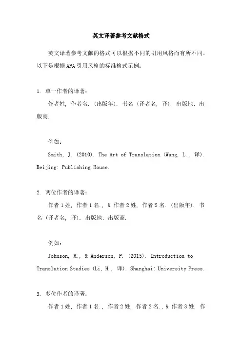
英文译著参考文献格式英文译著参考文献的格式可以根据不同的引用风格而有所不同。
以下是根据APA引用风格的标准格式示例:1. 单一作者的译著:作者姓, 作者名. (出版年). 书名 (译者名, 译). 出版地: 出版商.例如:Smith, J. (2010). The Art of Translation (Wang, L., 译). Beijing: Publishing House.2. 两位作者的译著:作者1姓, 作者1名., & 作者2姓, 作者2名. (出版年). 书名 (译者名, 译). 出版地: 出版商.例如:Johnson, M., & Anderson, P. (2015). Introduction to Translation Studies (Li, H., 译). Shanghai: University Press.3. 多位作者的译著:作者1姓, 作者1名., 作者2姓, 作者2名., & 作者3姓, 作者3名. (出版年). 书名 (译者名, 译). 出版地: 出版商.例如:Smith, J., Johnson, M., & Anderson, P. (2012). Comparative Translation Studies (Wu, Y., 译). Beijing: Publishing House.4. 编辑的译著:编者姓, 编者名. (Ed.). (出版年). 书名 (译者名, 译). 出版地: 出版商.例如:Brown, A. (Ed.). (2008). Translation and Language Teaching (Zhang, L., 译). Shanghai: University Press.需要注意的是,以上的格式是根据APA引用风格的标准来给出的示例,其他引用风格(如MLA、Chicago等)可能会有稍微的差异。

英语论文参考文献[1] samour, l.a. and r.e porter. intercultural communication: a reader (5thed) [m].wadsworth publishing co., 1988.[2] goodman k. s. reading: a psycholinguistic guessing game [j]. journal of reading, 1976.[3] anderson rc. frame works for comprehending discourse [j]. american educational research journal, 1997,14: 369.[4] 胡文仲小编. 文化艺术与人际交往[m]. 北京市:外语教学与研究出版社,1994.[5] 肖健硕. 英文学习方法[m]. 北京市:现代出版社,1997.[6] 马博森. 课堂教学中的话语分析方式,外国语教育探索[m]. XX年第2期63-66页.[7] 廖道胜.中国学生英文阅读中的人文阻碍,英语教学[m]. XX年第4期73-77.biographical datawang lin, holds a doctorate in comparative literature and is vice-professor and dean of the english department of foshan university. he specializes in english literature and translation. he teaches english reading, translation, english literature, english poetry and has translated more than twenty english fictional and non-fictional works, such as aesops fables, the black pearl, the naturalism, the president lady, and oscar wilde and his fairy tales. he has published over ten academic papers, among the major ones; a study on dubin's life, a study on translating criticism of creation society, oscar wilde and tian han,and a plan to explore the oral english teaching for students of non-english major.英语专业论文论文选题可分成下列好多个课程方位一、词汇学(语言学一般基础理论的科学研究);二、英美文学(英美文学的文化教育、著作研究等);三、翻译学(翻泽理论和实际讨论、译版科学研究及其名人名篇翻泽著作比照科学研究等);四、英美文化(美国英国加澳新等欧美国家文化艺术及其与中国文化的比较研究);五、教学方式(英语教学法、检测学等领域的科学研究)。
英文参考文献标准格式且使用斜体。
请参考举例(3)举例: (3)Smith。
J。
(2002)。
The XXX。
Journal of Environmental Science。
15(2)。
45-58.c).如果文献是电子文献,请参考举例(4)举例: (4)Johnson。
M。
(2010)。
The effects of social media on XXX参考文献:1.Doe。
J。
(2001)。
XXX。
94(3)。
10-20.2.Gao。
Y。
(2003)。
The role of government in economic development。
Beijing: China Press.3.Mettam。
G。
R。
& Adams。
L。
B。
(1994)。
How to prepare an electronic n of your article。
In B。
S。
Jones & R。
Z。
Smith (Eds.)。
n to the electronic age。
New York: E-Publishing Inc。
pp。
281-304.4.Smith。
J。
(1958)。
The effects of n on marine life。
Science。
125(3212)。
20-25.When writing academic papers。
it is important to follow the APA format。
which XXX n。
This format is required for those in the social sciences。
For journal articles。
an example of the APA format is: Van der Geer。
J。
Hanraads。
J。
A。
J。
& Lupton R。
A。
(2000)。
The art of writing a scientific article。
英文参考文献格式参考文献不仅有利于本科生的教育和管理,而且能为图书馆文献保障和读者服务等工作提供一定的参考依据。
下面,小编为大家分享英文参考文献格式,希望对大家有所帮助!参考文献的类型参考文献(即引文出处)的.类型以单字母方式标识,具体如下: M——专著C——论文集N——报纸文章 J——期刊文章D——学位论文R——报告对于不属于上述的文献类型,采用字母“Z”标识。
对于英文参考文献,还应注意以下两点:①作者姓名采用“姓在前名在后”原则,具体格式是:姓,名字的首字母.如:MalcolmRichardCowley应为:Cowley,M.R.,如果有两位作者,第一位作者方式不变,&之后第二位作者名字的首字母放在前面,姓放在后面,如:FrankNorris与IrvingGordon应为:Norris,F.&I.Gordon.;②书名、报刊名使用斜体字,如:MasteringEnglishLiterature,EnglishWeekly。
英文参考文献一:[1] Zhixin W, Chuanwen J, Qian A, et al. The key technology of offshore wind farm and its new development in China[J]. Renewable and Sustainable Energy Reviews, 2009, 13(1):216-222.[2] Shahir H, Pak A. Estimating liquefaction-induced settlement of shallow foundations by numerical approach[J]. Computers and Geotechnics, 2010, 37(3): 267-279.[3] Hausler EA. Influence of ground improvement on settlement and liquefaction:a study based on field case history evidence and dynamic geotechnicalcentrifuge tests. PhD dissertation, University of California, Berkeley; 2002.[4] Kemal Hac efendio lu. Stochastic seismic response analysis of offshore wind turbine including fluid‐structure‐soilinteraction[J]. Struct. Design Tall Spec. Build.,2010,[5] Arablouei A, Gharabaghi A R M, Ghalandarzadeh A, et al. Effects of seawater–structure–soil interaction on seismicperformance of caisson-type quay wall[J]. Computers &Structures, 2011, 89(23): 2439-2459.[6] Zafeirakos A, Gerolymos N. On the seismic response of under-designed caisson foundations[J]. Bulletin of Earthquake Engineering, 2013: 1-36.[7] Snyder B, Kaiser M J. Ecological and economic cost-benefit analysis of offshore wind energy[J]. Renewable Energy, 2009, 34(6):1567-1578.[8] Ding H, Qi L, Du X. Estimating soil liquefaction in ice-induced vibration of bucket foundation[J]. Journal of cold regions engineering, 2003, 17(2): 60-67.[9] Shooshpasha I, Bagheri M. The effects of surcharge on liquefaction resistance of silty sand[J]. Arabian Journal of Geosciences, 2012: 1-7.[10] Bhattacharya S, Adhikari S. Experimental validation ofsoil–structure interaction of offshore wind turbines[J]. Soil dynamics and earthquake engineering, 2011, 31(5): 805-816.[11] H. Bolton Seed, Izzat M. Idriss. Simplified procedure for evaluating soilliquafaction potential. Journal of the Soil Mechanics and Foundations Division. 1971,97(9): 1249-1273[12] W. D. Liam Finn, Geoffrey R.Martin, Kwok W.Lee. An effective stress model for liquefaction. Journal of the Geotechnical Engineering Division, 1977, 103(6):517-533[13] Seed.H.B.Soil liquefaction and Cyclic Mobility Evolution for Level Ground During Earthquakes, J of the Geotechnical Engineering Division ASCE , 1979,[14] Casagrande.A,Liquefaction and Cyclic Deformation of Sands-A Critical Review,Proceedings of the Fifth Pan American Conference on Soil Mechanics and Foundation Engineering,BuenosAires,Argentina,1975.英文参考文献二:[1] T. Paulay and J. R. Binney. Diagonally Reinforced coupling beams of shear Walls[S].ACI Special Publication 42, Detroit, 1974, 2: 579-598[2] Lam WY, Su R K L, Pam H J. Experimental study of plate-reinforced composite deep coupling beams[J]. Structural Design Tall Special Building, 2009(18): 235-257[3] ACI 318-02: Building Code Requirements for Structural Concrete, ACI318R-02:Commentary, An ACI Standard, reported by ACI Com-mittee318, American Concete Institute, 2002[4] Siu W H, Su R K L. Effects of plastic hinges on partial interaction behaviour of bolted side-plated beams[J]. Journal of Construction Steel Research, 2010, 66(5):622-633[5] Xie Q. State of the art of buckling-restrained bracesinAsia[J]. Journal of Construction Steel Research, 2005, 61(6):727-748[6] Kim J,Chou H. Behavior and design of structures withbuckling-restrained braces[J].Structural Engineering, 2004,26(6):693-706[7] Tsai K C, Lai J W. A study of buckling restrained seismic braced frame[J].Structural Engineering, Chinese Society of Structural Engineering, 2002, 17(2):3-32[8] Patrick J. Fortney, Bahrem M. Shahrooz, Gian A. Rassati. Large-Scale Testing of a Replaceable “Fuse” Steel Coupling Beam[J]. Journal of Structural Engineering.DECEMBER 2007:1801-1807[9] Qihong Zhao. Cyclic Behavior of traditional and Innovative Composite Shear Walls[J]. Journal of Structural Engineering, Feb. 2004:271-284。
三个人写的英文文章参考文献格式在撰写英文文章时,参考文献的格式对于文章的质量和可信度非常重要。
下面介绍三个人写的英文文章参考文献格式:1. 单一作者:参考文献格式:作者姓氏,作者名字缩写(年份)。
文章标题。
期刊名称,卷号(期号),页码。
例如:Smith, J. D. (2017). The effects of climate change on agriculture. Journal of Environmental Studies, 25(2),36-48.2. 两个作者:参考文献格式:作者1姓氏,作者1名字缩写,和作者2姓氏,作者2名字缩写(年份)。
文章标题。
期刊名称,卷号(期号),页码。
例如:Johnson, S. L., & Williams, K. A. (2016). The impact of technology on education. Educational Technology Research and Development, 64(3), 489-502.3. 多个作者:参考文献格式:第一作者姓氏,第一作者名字缩写,第二作者姓氏,第二作者名字缩写,以及其他作者(年份)。
文章标题。
期刊名称,卷号(期号),页码。
例如:Brown, J. M., Jones, K. L., Miller, R. P., et al. (2015). The incidence and prevalence of diabetes in the United States. Journal of Diabetes and Its Complications, 29(5),750-757.以上就是三个人写的英文文章参考文献格式,希望可以对大家的论文写作有所帮助。
英语论文参考文献格式用timesnewroman。
每一条目顶格,如某一条目超过一行,从第二行起“悬挂缩进”2字符。
参考文献中所有标点与符号均在英文状态下输入,标点符号后空一格。
参考文献条目排序顺序:英文文献、中文文献、网络文献。
分别按作者姓氏氏字母顺序排列。
文献前不用序号。
1)英文参考文献(1)专著与编著排序顺序为:作者姓氏、名、专知名、出版发行地、出版社、出版发行年。
brinkleyork:knopf,1993.专知名中如果还涵盖其他著作或作品名,后者用斜体。
dunn,richardjed.charlottebrontë:janeeyrenewyork:norton,1971.a.两个至三个作者第一作者的姓在前,名在后,中间用逗号隔开;其余作者名在前,姓在后,中间并无逗号;每个作者之间用逗号分隔,最后一个作者的姓名时用“and”,后用句号。
b.三个以上作者第一作者姓名(姓氏在前,名在后,中间提逗号)后直奔“etal.”,其他作者姓氏universityofhawaiipress,1997.c.同一作者同一年出版发行的相同文献,参考下基准:widdowson,henryg1998a.widdowson,henryg.cambridge:cambridgeuniversitypress,1998b.thompson,pett.“modalverbsinacademicwriting”.inbenkettlemann&york:rodopi,2002:305-323.(3)百科全书等参考文献fagan,jeffrey.“gangsanddrugs”.ork:macmillan,2001.(4)学术期刊论文murphy,karen.“meaningfulconnections:usingtechnologyinprimaryclassrooms”.(5)网络文献----“everythingyoueverwantedtoknowabouturl”.2)中文参考文献皮亚杰.结构主义[m].北京:商务印书馆,1984.(2)期刊文章杨忠,张韶杰.认知语音学中的类典型论[j].外语教学与研究,1999, (2):1-3.(3)学位论文梁佳.大学英语四、六级测试试题现状的理论分析与问题研究[d].湖南小学,2002.许小纯.含义和话语结构[a].李红儒.外国语言与文学研究[c].哈尔滨:黑龙江人民出版社,1999:5-7.。
英文引用及参考文献格式要求一、参考文献的类型参考文献即引文出处的类型以单字母方式标识,具体如下:M——专着C——论文集N——报纸文章J——期刊文章D——学位论文R——报告对于不属于上述的文献类型,采用字母“Z”标识;对于英文参考文献,还应注意以下两点:①作者姓名采用“姓在前名在后”原则,具体格式是:姓,名字的首字母.如:MalcolmRichardCowley应为:Cowley,.,如果有两位作者,第一位作者方式不变,&之后第二位作者名字的首字母放在前面,姓放在后面,如:FrankNorris与IrvingGordon 应为:Norris,F.&.;②书名、报刊名使用斜体字,如:MasteringEnglishLiterature,EnglishWeekly;二、参考文献的格式及举例1.期刊类格式序号作者.篇名J.刊名,出版年份,卷号期号:起止页码.举例1王海粟.浅议会计信息披露模式J.财政研究,2004,211:56-58.2夏鲁惠.高等学校毕业论文教学情况调研报告J.高等理科教育,20041:46-52.3Heider,2.专着类格式序号作者.书名M.出版地:出版社,出版年份:起止页码.举例4葛家澍,林志军.现代西方财务会计理论M.厦门:厦门大学出版社,2001:42.5Gill,M.London:Macmillan,1985:42-45.3.报纸类格式序号作者.篇名N.报纸名,出版日期版次.举例6李大伦.经济全球化的重要性N.光明日报,1998-12-273.7French,:AVoicefromChinaN.AtlanticWeekly,19871533.4.论文集格式序号作者.篇名C.出版地:出版者,出版年份:起始页码.举例8伍蠡甫.西方文论选C.上海:上海译文出版社,1979:12-17.9Spivak,G.“CantheSubalternSpeak”A.&eds..VictoryinLimbo:ImigismC.Urbana:UniversityofIllinoisPress,198 8,.。
英文会议参考文献格式
参考文献格式通常遵循以下结构:
作者姓氏, 名字的缩写. (发表年份). 标题. 期刊名称, 卷号(期号), 页面范围. DOI(如果有)
例如:
Cohen, J. (1994). The earth is round (p < .05). American Psychologist, 49(12), 997-1003. DOI: 10.1037/0003-
066X.49.12.997
如果参考文献是会议论文,则格式为:
作者姓氏, 名字的缩写. (会议发表年份). 论文标题. 在编辑者姓名(编者), 会议名称, 会议地点, 页面范围. 出版社。
例如:
Smith, J. (2003). The benefits of running: A case study. In M. Johnson (Ed.), Proceedings of the 5th Annual Conference on Physical Health and Fitness (pp. 78-89). Chicago, IL: University of Chicago Press.
需要注意的是,不同期刊和会议可能有不同的参考文献格式要求,需要按照期刊或会议官方的要求进行格式化。
Integration of modeling in solidworks and matlab/simulinkenvironmentsAbstractIn the paper, the authors present construction stages of simulation models worked out using SolidWorks and Matlab/Simulink environments. As examples of simulation models, a laboratory truck crane and a forest crane have been shown. These models allow for visualization of movements, tracking of the trajectory, velocity and acceleration of any point of the system.1. IntroductionCurrent technological development has caused an increase in customers’requirements as for designed products. Different conditions and competition on the market mean that new products must be characterized by high quality and functionality. This situation forces engineers to design machines which are characterized by great flexibility and a variety of applications. However, the construction of prototypes of all kinds of devices, which are subjected to experimental research, is impossible because of both economy and time. Therefore, modeling problem [1, 2] is useful and it plays a fundamental role in the design stage of a new structure as well as during the modification of an existing construction. The development of software used to computer- aided design causes that the geometrical models of objects not only can be built, but also one can perform kinematic, dynamic, and strength analysis on the basis of these models in the professional CAD system. However, it is complicated or even impossible to add the control in these applications. Therefore, very often modeling of control systems is performed in Matlab environment with Simulink module [3-6]. Other alternative, but rarely used method of visualization and control of movements of the working machines [7, 8], may be the Python programming language with appropriate libraries [9]. However, in this case, the preparation of simulation models is much more laborious and requires programming skills in Python. Matlab is intended to solve complex mathematical problems and generate a graphical visualization of theresults. Its scope includes various fields of science and technology. Matlab also provides numerous extensions (toolboxes), among them support for neural networks or optimization problems. One of the extensions is the SimMechanics Toolbox which facilitates the creation of kinematic chains, simulation of their dynamics and visualization of results. Simulink is a tool that allows defining the structure of the control system of mechanisms of the created models and displaying their simulation with complete control during a specified working cycle. This module makes it possible to create, in the graphical window, the structure of the control system which is built of various types of blocks representing dynamic objects, signal sources and measuring instruments. By defined objects, the software can refer to variables existing in memory and available in Matlab.In the paper, the authors present a course of simulation research carried out on the models elaborated with the use of SolidWorks [10, 11] and Matlab/Simulink.2. Construction of simulation modelThe simulation model is built in stages, that is, at first solid, surface, or hybrid model is created in one of the CAD program. SolidWorks, Pro/Engineer and Autodesk Inventor applications work preferably with the Matlab/Simulink environment.An assembly of elements can be used solely for simulation studies because in such cases there exists an interaction between individual parts, which in turn makes it possible to introduce the control system and perform motion analysis. Therefore, each created simulation model is an assembly of many individual parts or sub-assemblies. For instance, the sample CAD model presented in Figure 1 consists of: 3 assemblies and 8 parts, but these assemblies include subsequent assemblies or parts, etc.Building of each part of geometric model in SolidWorks, similar to the ones most currently used for this kind of applications, begins with defining a 2D geometry that creates a solid or a surface after completing one of numerous operations (e.g. extrusion or pocket). Then, based on expansion or modification of the obtained element made by removing or adding material, the creation of parts is continued. The majority of CAD systems offer normalized elements that can be used to build assemblies. The product that is the result of the final assembly of components has a permanent link to theFig. 1. Sample CAD model (model of laboratory truck crane)individual part files, which means that changes made in one of the files are automatically ascribed to the linked files, respectively. The product doesn’t have its own geometry, instead, it consists of a set of links to the parts and constraints that are used to connect these elements.The constructed geometric models should be parametric, which allows changing dimensions of components and their positions relative to each other in order to do analysis of motion according to the same model.Geometrical models can be used not only for the construction of the simulation model, but in a very simple way they can be utilized to carry out other types of analysis, such as modal or stress analysis. In this case, the calculation model which takes into account contact connections and boundary conditions should be worked out.The next stage of building the simulation model is the implementation of the CAD assembly model in Matlab/Simulink environment (Fig. 2).Fig. 2. Implementation process of CAD model in Matlab/Simulink environmentFor this purpose, besides previously mentioned CAD software and Mat- lab/Simulink, the SimMechanics Link utility has to be installed and linked to the CAD program [12].The first step of implementation process is to use the SimMechanics Link exporterto create Physical Modeling XML file that includes information about the mass and inertia of each part of the assembly, definitions of constraints between parts, as well as a set of STL (stereo-lithographic) files for representing surface geometries of the assembly bodies. The second step is import of the received files into the Matlab/Simulink program and generation of a SimMechanics model.The SimMechanics model, obtained immediately after the implementation, includes a block scheme (Fig. 3) and allows only visualizing mechanism or machine (Fig. 4), without a possibility of carrying out simulation research. Only rarely it is optimal, and does require modifications like removing unnecessary constraints between elements of the model or changing their types.Fig. 3. A sample SimMechanics block diagramFig. 4. Visualization of a sample SimMechanics model (model of laboratory truck crane Simulation tests may be carried out only after the control signals (e.g. kinematic excitations - Fig. 5) and the actuators are added to the model.In the created SimMechanics model, the control functions are sent to the actuators (Joint Block) with the use of the Joint Actuator block. Joint Block elements, those which occur between the parts of the model as the signal controllers, require movementparameters in the form of position, velocity and acceleration for the prismatic connection (Prismatic Joint) and the angular position, angular velocity and angular acceleration for the rotational connections (Revolute Joint). Because the defined control functions usually describe only velocity, therefore they should be integrated and differentiated through appropriate blocks (Fig. 6) and only at that point they can be sent to the Joint Actuator block in the form of three signals.Fig. 5. Sample control signalsIn order to improve the transparency of the block diagram, some blocks can be grouped together and transformed into the subsystems, additionally their appearance can be customized by using the process known as masking (the icons of subsystem blocks depict the real objects which they represent).The modified SimMechanics scheme (Fig. 3) after grouping, masking process and adding the control functions is illustrated in Figure 7.Fig. 6. Integration and differentiation of the control signalFig. 7. The modified SimMechanics scheme (model of laboratory truck crane)SimMechanics models allow determining variety of parameters, such as trajectory, velocity, and acceleration of any element of complex system by adding measuring instruments.Sometimes MATLAB/Simulink environment does not offer elements which appear in many simulation models. In such cases, it is possible to draw up own scripts and functions that can simulate such components.3.Examples of simulation modelsAs examples of simulation models worked out with the help of Solid- Works and Matlab/Simulink, the laboratory truck crane and forest crane have been shown.3.1. The simulation model of laboratory truck craneThe first example of a simulation model worked out according to the course presented in the section 2 illustrates the simulation model of a laboratory truck crane [13]. This model is based on an existing object located at the Institute of Mechanics and Machine Design Foundation of Czestochowa University of Technology [14]. Parametric geometrical model of this object is shown in Figure 1 and it includes, among other things, the platform with the three-member type telescopic boom, the hydraulic cylinder for crane radius change and the construction frame that imitates chassis and is supported on four bearings. All motions of the laboratory truck crane are actuated by hydraulic systems. Linear motions are realized by the hydraulic cylinders, while angular motions by the circulating cam hydraulic motors type SOK. Hydraulic systemsensure independent movements of: two telescopic boom members (second and third), slope of the telescopic boom and angle of rotation of the telescopic boom in the horizontal plane. The SimMechanics block diagram, (Fig. 3), obtained directly after implementation, has been modified by:-exchange of revolute joints between cylinder and piston rod of all hydraulic actuators for the prismatic joints,-removal of two prismatic joints between the second and third boom members of telescopic boom; in this case the other blocks ensure the correct action of the system.Moreover, the SimMechanics model has been supplemented with:-the Signal Builder block (Fig. 5) used to create the control functions of the laboratory truck crane,-Joint Actuators which force the movements of individual elements of the laboratory truck crane,-Body Sensors that read the motion parameters of individual system components, -Scope blocks for displaying signals generated during simulation. Besides, some objects were transformed into masked subsystems (Fig. 7). This model allows determination of motion parameters in the form of trajectory, velocity and acceleration of any element of the crane. One of the drawbacks of the presented model is that it does not take into account rope with the lifted load, for the simple reason that in Matlab/Simulink program there is no typical rope element. This problem has been solved by the use of assumptions and relationships presented, among other things, in works [15, 16] where the load is treated as a particle P that is hang on an inextensible rope (which is always lengthened) and fastened at the end of the telescopic boom. An additional moving rectangular coordinate system Ωξηζhas been inserted into the existing model; the origin of that system is at the end of the boom (Fig. 8).Fig. 8. Scheme of the basic motion of the lifted loadFor the above assumptions, the movement of a particle P in the global system, inwhich mass m is concentrated, can be described according to the relationships presented in the cited papers [15, 16] as:where the components aΩX,aΩY,aΩZ are accelerations of the boom end in the global system (which is rigidly connected with the crane frame and its origin is located in the support with the bearing), and their values are obtained directly from the simulation model. The system of motion equations (1,2,3) supplemented by the initial conditions:constitutes the initial problem of load movement. However, before the initial problem is solved with the help of the ode45 function available in Mat- lab/Simulink, the above equations must be entered in the form of scripts and functions using Matlab Function object into the SimMechanics model of the existing laboratory truck crane and, at the same time, the following elements must be added (Fig. 9):-Constant block for generating initial length of the rope,-Integrating and Differentiating Block,-Workspace Block in which the system response is collected in the form of data tables.Fig. 9. Modified SimMechanics modelSample studies on the above simulation model have been carried out for two cases:- free vibration of a mathematical pendulum moving in spatial motion, with an assumption that the suspension point remains stationary and is tied with the end of the telescopic boom,-motion of load treated as a response to the kinematic excitations.In both simulations, the mass of load is equal to 50 kg and the initial length of the rope (ρ0) is 1.5 m (length is measured from the end of the boom to the point of suspension of the load).For the spatial motion of the mathematical pendulum, the following conditions have been accepted:In Figure 10, there is shown a response of the system in the form of projections of load motion trajectory on the lifted (10a) and the rotary plane (10b).Fig. 10. Projection of load motion trajectory on the lifted (a) and rotary plane (b)For the case of solution of the initial conditions under the influence of kinematic excitations, the movement began from zero initial conditions, except forη(t)|t=0= 0.5 m, ζ (t)|t=0= ρ0 .The motion of lifted load was considered for the time equal 50 s. For the first 40 s, this motion was forced by the controls (Fig. 5) and, after their action ceased, for the next 10 s free oscillations of the lifted load were observed. The assumed motion sequences were directly connected with the working movements of the laboratory truck crane and they resulted from: control of rotation of platform (fi_prim), control of the boom inclination angle (teta_prim), control of the rope length which depends on the rope motion forced by the winch (ro_prim) and, finally, from the changes in the boom length (r_prim). All control functions were trapezoid pulses and included start-up, steady and braking movements.The system response to the taken kinematic excitations has been obtained in the form of animation of motion of the whole system in the SimMechanics Visualization window and in the form of projections of the lifted load motion trajectory on the lifted (Fig. 11a,b) and rotary planes (Fig. 11c).Fig. 11. Projection of the lifted load motion trajectory on the lifted (a, b) and rotary planes (c)3.2. The simulation model of the forest craneThe second simulation model [17, 18] concerns research on forest crane HIAB LOGLIFT F135 Z79 (Fig. 12), which consists of the following elements: - the basic member (1),- the internal arm (2),-the external arm - two-member telescopic boom (3),-the head (4), making up the place for fixing additional working equipment,-the hydraulic cylinder (5), used to change the inclination angle of the internal arm,-the set of two parallel hydraulic cylinders (6), applied for changing the inclination angle of the external arm,- the rotator - the hydraulic mechanism for performing rotational motion (7),-the manipulator - grab to wood (8),-the support system (9).Fig. 12. The forest crane HIAB LOGLIFT F135 Z79The worked out CAD model has been converted into the form of a physical model XML and implemented in Matlab/Simulink. Its visualization is shown in Figure 13 and block diagram is illustrated in Figure 14.The block scheme (Fig. 14) has been supplemented by an appropriate signal source, actuators and measuring instruments, i.e. Signal Builder objects to create time-courses of control signals, Joint Actuators controlling movements of individual crane arm, blocks setting the initial conditions, displacement and velocity sensors, tools for visualization of derived characteristics.The simulation model was used to carry out a sample simulation of machine cycle. During the working cycle, the machine mechanisms were controlled by time functions, presented in Figure 15, describing the changes of velocity of the following control signals:-control of rotation of primary column (Signal 1),- control of telescopic boom member (Signal 2),-control of deflection of the external arm from the vertical (Signal 3),F i g.13.V i s u a l i z a t i o n o f t h e f o r e s t c r a n e S i m M e c h a n i c s m o d e lFig. 14. The forest crane SimMechanics block scheme-control of deflection of the internal arm from the vertical (Signal 4).Based on the defined control functions, one obtained the trajectory of the point of attachment of the load, velocity and acceleration components in this movement. The system response is illustrated in Figures 16-18.Fig.15.Control signalsFig. 16. Position of the boom ends in the global coordinate systemThe presented simulation research on forest crane movement have been supported by animation of its motion in the SimMechanics Visualization. It allowed controlling correctness of motion system during a specified cycle.Fig. 17. Velocity of the boom ends in the global coordinate systemFig. 18. Acceleration of the boom ends in the global coordinate system4.ConclusionsIn this paper, we described the integration of SolidWorks and MAT- LAB/Simulink done through the implementation of CAD models, created previously in a SolidWorks program, into the Matlab/Simulink environment. We also presented an example of preparation of simulation models and their application to research on model properties.As examples of simulation models, the laboratory truck crane [13] and the forest crane [17, 18] have been shown.In the first case, on the basis of the constructed model, one can carry out simulation research allowing for visualization of movements, tracking of the trajectory, velocity and acceleration of any point of the system and tracking of the lifted load. Tracking of the lifted load was possible through developing the simulation model by adding scripts and functions including derivations of which can be found in works [15,16].In the second case, the results of research concerning determined movement of forest crane boom have been presented. The results of simulation studies, presented in this paper were confirmed by animations of the forest crane model motion. This model makes it possible to analyze the motion parameters of any boom member or arm of the forest crane and grab with the load.The presented sample of simulation models can be further developed by: -replacing the configuration of control operations assumed at the beginning with themovements performed by the operator (user) in real time,-replacing the kinematic excitations with the help of impact of power transmission and control systems, which makes it possible to get the feedback, which in turn facilitates positioning and reduces fluctuations of the load carried by crane, -taking into account physical properties (the deformability and damping) of a rope (in the case of the laboratory truck crane),-replacing particle P (load) with a rigid body (in the case of the laboratory truck crane).Despite minor imperfections, the Matlab/Simulink environment is one of the most popular and recognizable program for constructing simulation models.The main advantage of this program is the ability of constructing complex machine simulation models with the use of geometrical models created in other CAD programs without complex mathematical derivations. In this case, the user does not need to possess programming skills.One of the drawbacks of this method arises from the fact that all imported geometrical models are treated as rigid bodies. However, in the case when the flexibility of elements should be taken into account, one can attach a block from the Simulink Library Browser (where one exists), as well as write own scripts or/and functions to develop the created model. In such a situation, the capabilities of the constructed mathematical model are limited only by knowledge and skills of the designer.When flexibility of all elements must be taken into consideration, the CAD models are not used. Yet, all relationships are introduced directly in the form ofblocks offered by Matlab/Simulink software, own scripts or functions. An example of this approach is work [19], where the authors worked out a coupled dynamical model of the forest crane and the lifted load taking into account elastic deformations of the boom.AcknowledgmentThe study has been carried out within statutory research of the Institute of Mechanics and Machine Design Foundations of Czestochowa University of Technology.REFERENCES[1]Rusinski E.: Design principles for supporting structures of self-propelled vehicles. Oficyna Wydawnicza Politechniki Wroclawskiej, Wroclaw, 2002 (in Polish).[2]Eberhard P., Schiehlen W.: Hierarchical modeling in multibody dynamics. Archives of Applied Mechanics, 1998, 68, pp. 237-246.[3]Mrozek B., Mrozek Z.: MATLAB universal environment for scientific and technical calculations. CCATIE, Krakow, 1995 (in Polish).[4]Mrozek B., Mrozek Z.: MATLAB and Simulink. User’s guide. Helion, 2004 (in Polish).[5]Chaturvedi D.K.: Modeling and Simulation of Systems Using Matlab and Simulink. CRC Press, 2010.[6]Gran R.J.: Numerical Computing with Simulink, Volume I, Creating Simulation. Society for Industrial and Applied Mathematics, Philadelphia, 2007.[7]Cekus D., Waryg P., Wochal M.: The application of Python environment and CAD models to control of machine movements. Systems. Journal of Trandisciplinary Systems Science, 2012, Vol. 16, No 1, pp. 121-130 (in Polish).[8]Wochal M., Cekus D., Waryg P.: The application of VPython to visualization and control of robot. Pomiary Automatyka Robotyka, 2012, R. 16 nr 12 (190), pp. 151-156.[9]Scherer D., Dubois P., Sherwood B., VPython: 3D Interactive Scientific Graphics for Students. Computing in Science and Engineering, 2000, pp. 82-88.[10]Lombard M.: SolidWorks 2010 Bible. Wiley Publishing Inc., 2010.[11]Babiuch M.: SolidWorks 2006 w praktyce. Helion, 2007.[12]/help/physmod/smlink/index.html(access 25.07.2013).[13]Cekus D.: Modeling and simulation research of laboratory truck crane motion. Systems. Journal of Trandisciplinary Systems Science, 2012, Vol. 16, No 2, pp. 96-103 (in Polish).[14]Tomski L., Chwalba W.: System for testing the vibration of a truck-crane model. Materialy Sympozjum Naukowego “Metody Badan Maszyn Roboczych”. Prace Przemyslowego Insty- tutu Maszyn Budowlanych, 1989, z.1,2,3, pp. 206-214 (in Polish).[15]Posiadala B., Sklamierski B., Tomski L.: Motion of the lifted load brought bya kinematics forcing of the crane telescopic boom. Mechanism and Machine Theory, 1990, Vol. 25, Issue 5, pp. 547-556.[16]Posiadala B., Skalmierski B., Tomski L.: Theoretical, computational model of the telescopic mechanisms of the cranes. Prace Naukowe CPBP 02.05. Wydawnictwa Politechniki Warsza- wskiej, Warszawa, 1990 (in Polish).[17]Posiadala B. Paczynski A. Waryg P.: Implementation of the geometricalmodel of forest crane boom in Matlab-Simulink environment. Gornictwo Odkrywkowe, 2010, 3/2010, pp. 193-196 (in Polish).[18]Posiadala B., Wary^ P.: Modeling and simulation research of forest crane in operating cycle. Modelowanie Inzynierskie, 2011, 10(41), pp. 331-338 (in Polish).[19]Posiadala B., Waryg P., Cekus D., Tomala M.: The dynamics of the forest crane during the working cycle. International Journal of Structural Stability and Dynamics,2013,Vol.13,No.7,ArticleNumber:1340013(DOI:10.1142/S0219455413400 130).。