M8914-V1.1规格书(中文)
- 格式:pdf
- 大小:276.86 KB
- 文档页数:6
文诚系列技术培训手册清华紫光台式电脑事业部技术支持部2004-06-01目录一、产品特点1.1优良的品质保证1.2出色的结构设计1.3可靠的安全维护二、文诚系列主机配置2.1文诚系列主机配置表三、主板技术规格3.1 精英P6VEMD2主板说明3.2 精英L4S5MG/GX+主板说明3.3 技嘉GA-8I845GV-CH2说明四、驱动程序安装4.1驱动光盘说明4.2驱动程序安装目录一、产品特点文诚系列电脑强调性能价格比,适用于教育、网吧等中低端用户,便于集中管理,统一维护。
1.1优良的品质保证1)通过国家3C认证;2)严格的部件优选体制,所有部件采用业界一线厂商的产品;3)周密的测试全集,保证部件的兼容性,同时保证系统的稳定性;4)五年保修。
1.2出色的结构设计1)立卧两用,根据不同空间随意放置;2)机箱面板模块化设计,根据不同的应用选取不同外观;3)良好的散热设计,确保立卧使用时系统内部热量有效、及时的散发;4)静音设计,减少部件共振,优化风道,降低噪音。
1.3可靠的安全维护1)集成硬盘保护功能,保证硬盘数据的安全,遭到破坏一键恢复;2)同一机型间网络传输功能,维护好一台机器即可通过网络对其他机器进行维护;3)自动维护,无人值班的情况下对整个网络环境中的机器机型维护;4)预留机箱锁孔,防止非法开启机箱。
二、文诚系列主机配置(一)文诚500 文诚800 文诚1000E 文诚1100文诚1200 CPU C3800Celeron 1.8GCeleron 1.8G Celeron 1.8G Celeron 1.8G主板 P6VEMD2L4S5MG/GX+ L4S5MG/GX+ L4S5MG/GX+GA-8I845GV-CH2内存Twinmos 128MDDR333Twinmos 128MDDR333Twinmos 128MDDR333Twinmos 128MDDR333Twinmos 128MDDR333硬盘SeagateST340015ASamsungSV0411N(40GB/5400PRM)SeagateST340015ASamsungSV0411N(40GB/5400PRM)SeagateST340015ASamsungSV0411N(40GB/5400PRM)光驱LG CR-8523B LG GCR-8523B软驱SamsungSFD-321BSamsungSFD-321BSamsungSFD-321B显示卡主板集成主板集成主板集成主板集成主板集成声卡主板集成主板集成主板集成主板集成主板集成网卡主板集成主板集成主板集成主板集成主板集成电源长城 1801-HP 长城 1801-HP 长城 1801-HP 长城 1801-HP 长城 1801-HPCPU风扇主板集成Cool MasterDI4-7H53B/DI4-7H54A-R2Cool MasterDI4-7H53B/DI4-7H54A-R2Cool MasterDI4-7H53B/DI4-7H54A-R2/EC203MBCool MasterDI4-7H53B/DI4-7H54A-R2/EC203MB机箱保利得 EN7472 保利得 EN7472 保利得 EN7472 保利得 EN7472 保利得 EN7472键盘精模 JME7010 精模 JME7010 精模 JME7010 精模 JME7010 精模 JME7010鼠标致伸 M042K0 致伸 M042K0 致伸 M042K0 致伸 M042K0 致伸 M042K0驱动光盘智能驱动光盘V2.0智能驱动光盘V2.0智能驱动光盘V2.0/2.1智能驱动光盘V2.0文诚系列主机配置(二)三、主板技术规格3.1文诚500采用的主板是:精英P6VEMD2,采用VIA CLE266 CE / VT8235 CD 芯片组。
DATA SHEETIntroduction Performance Characteristics Mechanical Dimensions Characteristic Curves ReliabilityPacking Specification PrecautionP 2P 3P 5P 6P 9P 10P 11 CITILED COB SeriesStandard Type.Ra70 Min., Ra80 Min. Model CLU04Q-1212E11. Introduction1-1. Product Description1-2. Features・Mechanical Dimensions :28 × 28 × 1.4 (mm)・Package Structure :Aluminum Base Chip on Board ・Reference Assembly :M3 screw, Connector ・CRI (Ra):70 Min., 80 Min.・Nominal CCT :3,000K, 4,000K, 5,000K ( CRI(Ra) 70Min. )2,700K, 3,000K, 3,500K, 4,000K, 5,000K, 5,700K, 6,500K ( CRI(Ra) 80Min. )・Chromaticity Range:3-step Ellipse, the center refers to ANSI C78.377:2017. ( CRI(Ra) 70Min. )2-step Ellipse, the center refers to ANSI C78.377:2017. ( CRI(Ra) 80Min. )・Thermal Resistance :0.32C/W ・Maximum drive current :2760mA ・UL recognized component (E358566)・RoHS compliant・Better die arrangement for optics・Wide range of luminous flux and high efficacy・Improved lumen density compared with previous version CLU04Q -1212E1-303L7X4[1][2][3][4][5][1]:[2]:[3]:[4]:[5]:Nominal CCT CRI (Ra)Product NomenclatureCLU04Q 12123000K 70 Min.Product shape Die count in series Die count in parallel CITIZEN ELECTRONICS is the first COB manufacturer.With many years of knowledge, experience, and advanced packaging technology, we continue to produced high quality and highly reliable products.The new COB series, Version9, while keeping the conventional product lineup and package sizes, achieves both high color quality (2 Step ellipse) and higher driving capability.In addition, efficacy and reliability are improved by selecting superior materials and optimizing production processes.Our highly reliable and efficient COB light source contributes to the realization of a circular economy through energy saving and reduction of carbon emissions.2. Performance Characteristics2-1. Electro Optical Characteristics2-2. Absolute Maximum RatingsSymbol RatingPi 116.5*1If 2760*1Ir 1Top -40 ~ +100Tst -40 ~ +100Tc 120*2Tj140*3*2. Refer to 3. Outline drawing for Tc measurement point.*3. Junction temperature calculation formula : Tj = Tc + Rj-c × PiParameterInput Power (W)Forward Current (mA)Reverse Current (mA)Storage Temperature (C)Case Temperature (C)Junction Temperature (C)Operating Temperature (C)*1. Input power and forward current are the values when the LED is used within the range of the derating curve in this data sheet.( Tj=85C )Ra R9Tc25C*Min.Min.Min.Typ.Typ.Typ.Min.Typ.Max.CLU04Q-1212E1-303L7X43000K 70-5,6566,4286,9251761,08031.433.836.20.32CLU04Q-1212E1-403L7X44000K 70-5,6896,4656,9651771,08031.433.836.20.32CLU04Q-1212E1-503L7X45000K 70-5,7106,4896,9911781,08031.433.836.20.32CLU04Q-1212E1-272M2X22700K 8004,9915,6736,1111551,08031.433.836.20.32CLU04Q-1212E1-302M2X23000K 8005,1845,8926,3471611,08031.433.836.20.32CLU04Q-1212E1-352M2X23500K 8005,3036,0276,4931651,08031.433.836.20.32CLU04Q-1212E1-402M2X24000K 8005,4256,1666,6421691,08031.433.836.20.32CLU04Q-1212E1-502M2X25000K 8005,4096,1476,6231681,08031.433.836.20.32CLU04Q-1212E1-572M2X25700K 8005,3546,0856,5561671,08031.433.836.20.32CLU04Q-1212E1-652M2X26500K805,3046,0276,4941651,08031.433.836.20.32Notes :1. Citizen Electronics maintains a tolerance of ± 10% on luminous flux measurements.2. Citizen Electronics maintains a tolerance of ± 3% on forward voltage measurements.3. Citizen Electronics maintains a tolerance of ± 2 on Ra measurements. * : Values of Luminous flux at Tc=25C are provided as reference only.Product codeForward Current( mA )Thermal Resistance Rj-c ( C/W )CRI Nominal CCTLuminous flux( lm )Efficacy ( lm/W )Forward Voltage( V )Tj85C2,700K ( 0.4578, 0.4101)3,000K( 0.4339, 0.4033)3,500K ( 0.4078, 0.3930)4,000K ( 0.3818, 0.3797)5,000K ( 0.3446, 0.3551)5,700K ( 0.3287, 0.3425)6,500K( 0.3123, 0.3283)3-step Ellipse.2-step Ellipse.Color RegionNominal CCT Center Point ( x, y )---0.003540.00236-0.00507-0.001983-step 2-step 0.0083452.970.00634-0.00278 ( Rated current, Tj=85C )53.170.005560.004080.002720.00516-0.0027457.28Oval parameterMajor Axisa Minor Axisb E llipse Rotation Angleθ3-step 2-step * Color region stay within 3-step / 2-step ellipse from the chromaticity center.* The chromaticity center refers to ANSI C78.377:2017.* θ is the angle between the major axis of the ellipse and the x-axis, and a and b are the major and minor semi-axes of an ellipse.54.0059.6258.3859.460.009390.006260.004020.002680.00446-0.001900.008220.005482-3. Chromaticity CharacteristicsNote : Citizen Electronics maintains chromaticity ( x, y ) +/-0.0050.300.350.400.450.300.350.400.450.50yxx-y chart CIE19314,000K3,000KBlack Body Locus2,700K3,500K5,000K5,700K6,500K2-step 3-step3. Mechanical DimensionsUnit : mmTolerances unless otherwise specified : +/-0.3・Internal Circuit12 S 12 P Protection deviceLED deviceCathodeAnodeMarking 1 : Serial No.Marking 2 : Code No.CRI CCTDie count in parallel Die count in seriesCLU0xQ seriesMarking 3 : Data MatrixAN 12 12 ** ** *4. Characteristic Curves4-1. Forward Current Characteristics / Temperature CharacteristicsForward Current vs. Forward VoltageForward Current vs. Relative Luminous FluxTc=25CTc=25CCase Temperature vs. Forward VoltageCase Temperature vs. Relative Luminous FluxIf=1080mAIf=1080mA30.032.034.036.038.040.00100020003000V f [V ]If [mA]0%50%100%150%200%250%100020003000R e l a t i v e L u m i n o u s F l u x [a .u .]If [mA]32.033.034.035.036.0255075100125V f [V ]Tc [C]0%20%40%60%80%100%120%0255075100125R e l a t i v e L u m i n o u s F l u x [a .u .]Tc [C]4-2. Optical CharacteristicsTj=85CIf=1080mASpectrum : CRI(Ra) 80 Min.0%10%20%30%40%50%60%70%80%90%100%380430480530580630680730780R a d i a t i v e I n t e n s i t yWave length [nm]6,500K5,700K 5,000K 4,000K 3,500K 3,000K2,700KTj=85CIf=1080mASpectrum : CRI(Ra) 70 Min.0%10%20%30%40%50%60%70%80%90%100%380430480530580630680730780R a d i a t i v e I n t e n s i t yWave length [nm]5,000K4,000K3,000K4-2. Optical Characteristics (continued)4-3. Derating CharacteristicsRadiation Characteristic0%20%40%60%80%100%X Y80°70°60°50°40°30°20°10°-80°-70°-60°-50°-20°-30°-40°-10°90°-90°Case Temperaturevs. Allowable Forward Current1000200030000255075100125I f [m A ]Tc [C]5. Reliability5-1. Reliability Test5-2. Failure Criteria-40 C × 30 minutes – 100 C × 30 minutes, 100 cycle85 C, 85 %RH for 500 hoursThermal Shock TestContinuous Operation Test High Temperature Storage TestLow Temperature Storage Test Moisture-proof Test If=1080mA , Tj=140C (with Al-fin) ×1000hoursTest Item100 C × 1000 hours -40 C × 1000 hours Test ConditionIf=1080mA , Ta= 25C (with Al-fin) ×1000hours ( Tc=25C )U defines the upper limit of the specified characteristics. S defines the initial value.Note : Measurement shall be taken between 2 hours and 24 hours, and the test pieces should be return to the normal ambient conditions after the completion of each test.Total Luminous FluxΦvIf=1080mA<S × 0.85Measuring Item Symbol Measuring ConditionFailure CriteriaForward Voltage Vf If=1080mA >U × 1.1Unit : mmProduct : 30 pcs/tray1. TYPEe.g. CLU04Q-1212E12. P.No. ( Customer's P/N )3. Lot No.2175015(b)(a) Last two digit of the year 21 : Year 2021(b) Production month 7 : JulyNote: October, November and December are designated X,Y and Z.(c) CE's control number 4. Quantity(a)(c)Example of indication labele.g. 6. Packing Specification6-1. PackingAn empty tray is placed on top of a 6-tier tray which contain 30 pieces each.( Smallest packing unit : 180 pieces )A label with product name, quantity and lot number is placed on the upper empty tray.Tray ( Dimensions: 310 x 210 x 12 mm / Materials: Electrically conductive PS ) CUSTOMERTYPE P.NO Lot No Q'ty: CLU***-******-******* : ****** : ******* : ***--- ( 1 ) --- ( 2 ) --- ( 3 ) --- ( 4 )7. Precaution7-1. Handling with care for this product-Both the light emitting area and white rim around the light emitting area is composed of resin materials.Please avoid the resin area from being pressed, stressed, rubbed, come into contact with sharp metal nail(e.g. edge of reflector part) because the function, performance and reliability of this product are negatively impacted.-Please be aware that this product should not come into contact with any other parts while incorporating in your lightingapparatus or your other products.-Please be aware that careful handling is required after the attachment of lead wires to prevent the application of any loadto the connections.-For more information, please refer to application note "Instruction Manual(COB LED Package)".7-2. Countermeasure against static electricity-Handling of this product needs countermeasures against static electricity because this is a semiconductor product.-Please take adequate measures to prevent any static electricity being produced such as the wearing of a wristband oranti-static gloves when handling this product.-Every manufacturing facility in regard to the product (plant, equipment, machine, carrier machine and conveyance unit)should be connected to ground and please avoid the product to be electric-charged.-ESD sensitivity of this product is over 1000V (HBM, based on JEITA ED-4701/304).-After assembling the LEDs into your final product(s), it is recommended to check whether the assembled LEDs aredamaged by static electricity (electrical leak phenomenon) or not.-It is easy to find static damaged LED dies by a light-on test with the minimum current value.7-3. Caution of product assembly-Regarding this product assembling on the heat sink, it is recommended to use M3 screw.It might be good for screw tightening on the heat sink to do temporary tightening and final tightening.In addition, please don’t press with excess stress on the product.-The condition of the product assembling on the heat sink and the control of screw tightening torque needs to be optimized according to the specification of the heat sink.-Roughness, unevenness and burr of surface negatively impact thermal bonding between the product and heat sink andincrease heat thermal resistance between them.Confidence of thermally and mechanical coupling between the product and heat sink are confirmed by checkingthe mounting surface and measuring the case temperature of the product.-In order to reduce the thermal resistance at assembly, it might be good to use TIM (Thermal Interface Material) on whole contact surface of the product.In case of using thermal grease for the TIM, it might be good to apply uniformly on the contact surface of the product.In case of using thermal sheet for the TIM, it might be good to make sure that the product is NOT strained by stress when the screws are tightened for assembly.-For more information, please refer to application note "Instruction Manual(COB LED Package)".7-4. Thermal Design-The thermal design to draw heat away from the LED junction is most critical parameter for an LED illumination system. High operating temperatures at the LED junction adversely affect the performance of LED’s light output and lifetime. Therefore the LED junction temperature should not exceed the absolute maximum rating in LED illumination system. -The LED junction temperature while operation of LED illumination system depends upon thermal resistance of internal LED package (Rj-c), outer thermal resistances of LED package, power loss and ambient temperature. Please take both of the thermal design specifications and ambient temperature conditions into consideration for the setting of driving conditions.-For more information, please refer to application note "Thermal Management", "Instruction Manual(COB LED Package)".7-5. Driving Current-A constant current is recommended as an applying driving current to this product.In the case of constant voltage driving, please connect current-limiting resistor to each products in series and control the driving current to keep under the absolute maximum rating forward current value.-Electrical transient might apply excess voltage, excess current and reverse voltage to the product(s).They also affect negative impact on the product(s) therefore please make sure that no excess voltage, no excess current and no reverse voltage is applied to the product(s) when the LED driver is turn-on and/or turn-off.-For more information, please refer to application note "Driving", "Instruction Manual(COB LED Package)".7-6. Lighting at a minimum current value-A minimum current value of lighting of all dice is 15mA.When a minimum current is applied, LED dice may look different in their brightness due to the individual difference of the LED element, and it is not a failed product.7-7. Electrical Safety-This product is designed and produced according to IEC 62031:2008(IEC 62031:2008 LED modules for general lighting. Safety specification)-Dielectric voltage withstand test has been conducted on this product to see any failure after applyingvoltage between active pads and aluminum section of the product, and to pass at least 500V.-Considering conformity assessment for IEC62031:2008, almost all items of the specification depend uponyour final product of LED illumination system.Therefore, please confirm with your final product for electrical safety of your product.As well, the products comply with the criteria of IEC62031:2008 as single LED package.- A minimum current value of lighting of all dice is 60 mA. When a minimum current is applied, LED dice may look different in their brightness due tothe individual difference of the LED element, and it is not a failed product.7-8. Recommended soldering Condition (This product is not adaptable to reflow process.) -For manual solderingPlease use lead-free soldering.Soldering shall be implemented using a soldering bit at a temperature lower than 350C, and shall befinished within 3.5 seconds for one land.No external force shall be applied to resin part while soldering is implemented.Next process of soldering should be carried out after the product has return to ambient temperature.Contacts number of soldering bit should be within twice for each terminal.* Citizen Electronics cannot guarantee if usage exceeds these recommended conditions.Please use it after sufficient verification is carried out on your own risk if absolutely necessary.-For more information, please refer to application note "Instruction Manual(COB LED Package)".7-9. Eye Safety-The International Electrical Commission (IEC) published in 2006 IEC 62471”2006 Photobiological safety of lamps and lamp systems ” which includes LEDs within its scope.When sorting single LEDs according to IEC 62471, almost all white LEDs can be classifiedas belonging to either Exempt Group (no hazard) or Risk Group 1 (low risk).-However, Optical characteristics of LEDs such as radiant flux, spectrum and light distribution are factorsthat affect the risk group determination of the LED, and especially a high-power LED, that emits lightcontaining blue wavelengths,might have properties equivalent to those of Risk Group 2 (moderate risk).-Great care should be taken when directly viewing an LED that is driven at high current, has multipleuses as a module or when focusing the light with optical instruments, as these actions might greatlyincrease the hazard to your eyes.-It is recommended to regard the evaluation of stand-alone LED packages as a referenceand to evaluate your final product.7-10. This product is not designed for usage under the following conditions.If the product might be used under the following conditions, you shall evaluate its effect and appropriate them. In places where the product might:-directly and indirectly get wet due to rain and/or at place with the fear.-be damage by seawater and/or at place with the fear-be exposed to corrosive gas (such as Cl2, H2S, NH3, SOx, NOx and so on) and/or at place with the fear.-be exposed to dust, fluid or oil and/or at place with the fear.Precautions with regard to product use(1) This document is provided for reference purposes only so that CITIZEN ELECTRONICS' products are used as intended. CITIZEN ELECTRONICS neither makes warranties or representations with respect to the accuracy or completeness of the information contained in this document nor grants any license to any intellectual property rights or any other rights of CITIZEN ELECTRONICS or any third party with respect to the information in this document. Before purchasing or using any CITIZEN ELECTRONICS' products listed in this document, please confirm the latest product information with a CITIZEN ELECTRONICS‘s sales office, and formal specifications must be exchanged and signed by both parties prior to mass production.(2) All information included in this document such as product data, diagrams, charts, is current as of the date this document is issued.Such information, however, is subject to change without any prior notice.(3) CITIZEN ELECTRONICS has used reasonable care in compiling the information included in this document, but CITIZEN ELECTRONICS assumes no liability whatsoever for any damages incurred as a result of errors or omissions in the information included in this document.(4) Absent a written signed agreement, except as provided in the relevant terms and conditions of sale for product, and to the maximum extent allowable by law, CITIZEN ELECTRONICS assumes no liability whatsoever, including without limitation, indirect, consequential, special, or incidental damages or loss, including without limitation, loss of profits, loss of opportunities, business interruption and loss of data, and disclaims any and all express or implied warranties and conditions related to sale, use of product, or information, including warranties or conditions of merchantability, fitness for a particular purpose, accuracy of information, or no infringement.(5) Though CITIZEN ELECTRONICS works continually to improve products' quality and reliability, products can malfunction or fail. Customers are responsible for complying with safety standards and for providing adequate designs and safeguards to minimize risk and avoid situations in which a malfunction or failure of a product could cause loss of human life, bodily injury or damage to property, including data loss or corruption. In addition, customers are also responsible for determining the appropriateness of use of any information contained in this document such as application cases not only with evaluating by their own but also by the entire system. CITIZEN ELECTRONICS assumes no liability for customers' product design or applications.(6) The LEDs described in this brochure are intended to be used for ordinary electronic equipment (such as office equipment, communications equipment, measurement instruments and household appliances). Consult Citizen Electronics’s sales staff in advance for information on the applications in which exceptional quality and reliability are required, particularly when the failure or malfunction of the LEDs may directly jeopardize life or health ( such as for airplane, aerospace, submersible repeaters, nuclear reactor control system, automobiles, traffic control equipment, life support system and safety devices ) . This LED does not comply with ISO/TS 16949 (IATF16949) and is not intended for automotive applications.(7) The customer shall not reserve engineer by disassembling or analysis of the LEDs without having prior written consent from Citizen Electronics. When defective LEDs are found, the customer shall inform Citizen Electronics before disassembling or analysis.(8) When exporting our products, please ensure conformance with applicable laws and regulations and take appropriate actions such as obtaining an export license.(9) Please do not use or supply our products for any weapons of mass destruction (WMD) or for any other military purposes.(10) Please contact CITIZEN ELECTRONICS' sales office if you have any questions regarding the information contained in this document, or if you have any other inquiries.is a trademark or a registered trademark of CITIZEN ELECTRONICS CO., LTD. JAPAN. **********************.co.jp。
® U.S. Registered TrademarkCopyright © 1996 Honeywell Inc. • All Rights ReservedSPECIFICATION DATA63-1156-2M6161, M6181, M6184, M6191, M6194Modutrol IV ™ Motorsu M6161u M6181u M6184u M6191u M6194FEATURES•Replace M644 Motors.•Oil immersed motor and gear train provides reliable performance and long life.•Wiring box provides NEMA 3 weather protection.•Quick-connect terminals standard—screw terminal adapter available.•Adapter bracket for matching shaft height of older motors is standard with replacement motors.•Die-cast aluminum housing•Integral auxiliary switches are available factory mounted or can be field added to TRADELINE®models.APPLICATIONThese Modutrol IV Motors are 3-wire floating control motors used with controllers that provide spdt or floating output to operate dampers or valves.2M6161, M6181, M6184, M6191, M6194 Modutrol IV™ MOTORS63-1156—2SPECIFICATIONSTRADELINE ® ModelsTRADELINE models are selected and packaged to provide ease of stocking, ease of handling, and maximumreplacement value. TRADELINE model specifications are the same as those of standard models, unless otherwisespecified. M6184D1035 and M6194D1017 are TRADELINE models. TRADELINE models have auxiliary switch cams.Standard ModelsM6161A,B M6181A,D,F M6184A,B,D,F M6191A,B,D M6194A,B,D,E,FN N N NControl Type Suffix Letter 61is Series 60A:Fixed stroke(90° or 160°),Power Rating No auxiliary switches 6is low torque:B:Fixed stroke35 lb-in.(90° or 160°),8is high torque:1 auxiliary switch 150 lb-in. at standard D:Adjustable stroketiming (60 sec for 160°)(90° to 160°),9is extra high torque:No auxiliary switches 300 lb-in. at 2 or 4E:Adjustable strokeminute timing (90° to 160°),Output Drive2 auxiliary switches 4is dual-ended shaft,F:Adjustable strokenon-spring return (90° to 160°),1is single-ended shaft,2 auxiliary switchesnon-spring returnNOTE:Some motors are furnished to HVAC equipmentmanufacturers with no adapter bracket, a single-ended shaft and/or no wiring box.Dead Weight Load on Shaft:Power or Auxiliary End: 200 lb (90.8 kg) maximum.Maximum Combined Load: 300 lb (136 kg).Ambient Temperature Ratings:Maximum: 150°F (66°C) at 25% duty cycle.Minimum: Minus 40°F (-40°C).Crankshaft: 3/8 in. (9.5 mm) Square.M6184, M6194 have dual-ended shaft.M6161, M6181, M6191 have single-ended shaftController Type:Floating 3-wire (Series 60)—drive open, hold, drive closed.Stroke:Fixed stroke models available with 90° or 160° stroke. Other models available with stroke field adjustable from 90° to 160°.Start position of shaft changes with adjustment of stroke.(Midpoint of stroke remains fixed as stroke is adjusted.)Stroke is adjusted using cams located in wiring compartment.Dimensions:See Fig. 1.Underwriters Laboratories Inc. Listed:File No. E4436, Guide No. XAPX.Canadian Standards Association Certified:General Listing File No. LR1620, Guide No. 400-E.Timing and Torque:M6161, M6181, M6184, M6191, M6194 Modutrol IV™ MOTORS363-1156—2Accessories:ES650117 Explosion-proof Housing: Encloses motor for use in explosive atmospheres. Not for use with Q601,Q618, and Q455 Linkages. Order separately from Nelson Electric Co. Requires Honeywell 7617DM Coupling.Q607 External Auxiliary Switch: Controls auxiliary equipment as a function of motor position.Internal Auxiliary Switch Kits: Can be field-installed on TRADELINE models.220736A—One-switch Kit.220736B—Two-switch Kit.Q605 Damper Linkage: Connects motor to damper.Includes motor crank arm.Q618 Linkage: Connects Modutrol motor to water or steam valve.Q601 Bracket and Linkage Assembly: Connects Modutrol motor to water or steam valve.Q100A,B Linkage: Connects Modutrol motor to butterfly valve.Q68 Dual Control Potentiometer: Controls 1 through 9additional motors.Q181 Auxiliary Potentiometer: Controls 1 or 2 additional motors.221455A Infinitely Adjustable Crank Arm: Approximately 0.75 in. (19 mm) shorter than the 4074EL Y Crank Arm.Can rotate through downward position and clear base of motor without requiring use of adapter bracket.7617ADW Adjustable Crank Arm: Approximately 0.75 in.(19 mm) shorter than the 7616BR Crank Arm. Can rotate through downward position and clear base of motor without requiring use of adapter bracket.220741A Screw Terminal Adapter: Converts the standard quick-connect terminals to screw terminals.Transformers: Mounted internally, provide 24 Vac power to motor.198162JA—24 Vac; 50/60 Hz (for electrical isolation).198162EA—120 Vac; 50/60 Hz.198162GA—220 Vac; 50/60 Hz.198162AA—120/208/240 Vac; 50/60 Hz.BASE ENDFig. 1. Dimensions in in. (mm). Note: M6161, M6181, M6191 models do not have auxiliary shaft.All other dimensions are the same.463-1156—2Honeywell Europe S.A.3 Avenue du Bourget B-1140 Brussels BelgiumHoneywell Asia Pacific Inc.Room 3213-3225Sun Hung Kai Centre No. 30 Harbour Road Wanchai Hong KongHome and Building ControlHoneywell Limited-Honeywell Limitée 155 Gordon Baker Road North York, Ontario M2H 2C9Honeywell Latin American Division Miami Lakes Headquarters14505 Commerce Way Suite 500Miami Lakes FL 33016Helping You Control Your World63-1156—2 G.R. Rev. 5-96Home and Building Control Honeywell Inc.Honeywell Plaza P.O. Box 524Minneapolis MN 55408-0524Printed in U.S.A. on recycled papercontaining at least 10% post-consumer paper fibers By using this Honeywell literature, you agree that Honeywell will have no liability for any damages arising out of your use or modification to, the literature. You will defend and indemnify Honeywell, its affiliates and subsidiaries, from and against any liability, cost, or damages, including attorneys’ fees, arising out of, or resulting from, any modification to the literature by you.。
用户手册彩色喷墨多功能一体机C4**Ws系列/L5**Ws系列·感谢您选购得力产品。
·对您使用得力系列产品我们表示衷心的感谢!·产品外观请以实物为准(各型号外观存在差异)。
·为了保障您的切身权益,请认真阅读下面的声明内容。
·如需更多帮助请登录:·版本:1.1©2022宁波得力集团有限公司产品各型号功能简介·“●”表示支持,“-”表示不支持。
·如有产品系列增加或变更,恕不另行通知。
·本说明书中的产品图片大部分以L511Ws为例,少部分以C411Ws为例,由于机型不同可能出现外形不同。
关于废旧机器与耗材的回收得力集团有限公司作为一家具有社会责任感的企业,为了倡导绿色环保,以及为可持续发展作贡献,您购买的本公司生产的打印设备及耗材在需废弃时,可交由本公司进行免费回收处理,详细如下:1.您可以拔打得力集团全国服务热线400-185-0555进行登记确认,并按服务热线提供的地址将这些废弃物交到或寄送到得力集团就近的分部或得力集团服务中心。
按照共同有责共同负担的原则,该环节所发生的运费等相关费用由交付者自行承担。
2.得力集团各分部将回收的废弃物统一送回集团服务中心,再由集团服务中心按照国家环境保护法相关法律规定交由具备国家认可资质的回收单位进行专业回收和处理。
该环节所发生的运费、回收处理费等费用由得力集团有限公司承担。
关于零配件(组件)、耗材提供本打印机停产后,部分零配件(组件)、耗材(打印头、墨水瓶、墨盒)还会提供5年。
关于产品放置的建议建议您将本产品放置于相对通风和独立的区域。
关于使用再生纸的建议为节约资源,促进绿色环保,您也可以使用品质稳定的再生纸。
关于零能耗的建议本产品只有拔下电源插头才能实现零能耗。
目录产品各型号功能简介 (2)关于废旧机器与耗材的回收 (2)目录 (4)重要指导 (6)注意事项及安全 (6)关于本用户手册 (6)一般安全信息 (6)设备安放的位置 (7)电气安全 (8)保修 (8)打印头.墨水瓶.墨盒 (8)维修保养 (8)无线电干扰 (9)警告 (9)设备中有毒有害物质或元素名称及含量 (10)使用入门 (11)打印机部件 (11)控制面板 (12)装入纸张 (13)放入原稿 (13)连接设备使用打印机 (14)手机给打印机配网(推荐家庭和个人) (14)电脑为打印机配网 (14)打印 (23)使用【得力喷墨打印机助手】进行打印 (23)使用【得力随心印】微信小程序进行打印 (28)复印和扫描 (29)身份证黑白复印(主机) (29)复印设置(主机) (29)使用【得力喷墨打印机助手】进行扫描 (30)使用【得力随心印】微信小程序进行扫描 (32)使用Web服务 (33)什么是Web服务? (33)通过网络访问Web界面 (33)Web主界面 (34)管理墨水和打印头 (36)保持通电 (36)校准打印头 (36)清洁打印头 (37)关于使用墨水和打印头的提示 (38)墨水处理注意事项 (38)故障排除 (39)检查本产品的状态-打印机 (39)卡纸问题 (41)进纸问题 (42)打印问题 (42)扫描问题 (46)解决无法使用Web服务的问题 (46)恢复出厂设置 (46)固件升级 (46)光栅条脏污 (47)附录 (48)产品规格表 (48)复印限制 (49)重要指导注意事项及安全操作本设备前,请仔细阅读以下说明,并根据需要进行参考,确保设备的持续安全运行。
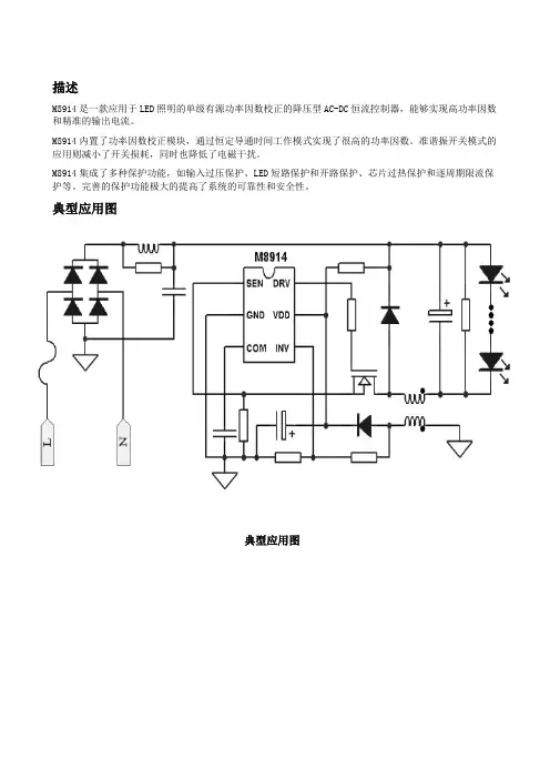
描述M8914是一款应用于LED照明的单级有源功率因数校正的降压型AC-DC恒流控制器,能够实现高功率因数和精准的输出电流。
M8914内置了功率因数校正模块,通过恒定导通时间工作模式实现了很高的功率因数。
准谐振开关模式的应用则减小了开关损耗,同时也降低了电磁干扰。
M8914集成了多种保护功能,如输入过压保护、LED短路保护和开路保护、芯片过热保护和逐周期限流保护等。
完善的保护功能极大的提高了系统的可靠性和安全性。
典型应用图典型应用图特征内置单级有源功率因数校正功能,PF>0.9精准的LED电流控制准谐振开关模式减小开关损耗,提高系统效率 输出电流精度±5%优异的线电压调整率和负载调整率极低的启动电流,典型值15μA可靠的LED开路/短路保护功能系统自动重启功能VCC过压保护/欠压保护逐周期限流保护芯片过温保护SOT-23-6封装应用领域适用于中小功率AC/DC离线式开关电源。
AC-DC非隔离型LED照明球泡灯射灯日光灯管引脚功能描述引脚配置图极限参数注:如果器件工作条件超出上述各项极限值,可能对器件造成永久性损坏。
上述参数仅仅是工作条件的极限值,不建议器件工作在推荐条件以外的情况。
器件长时间工作在极限工作条件下,其可靠性及寿命可能受到影响。
芯片框图应用信息●描述M8914是一款集成功率因数校正功能的单级降压型LED驱动芯片,通过专有的恒流控制技术实现了优异的恒流特性,可广泛应用于高性能LED照明系统。
有源功率因数校正功能可大大降低对电网的谐波干扰,是一项绿色节能的技术。
芯片工作于准谐振模式,可以实现很低的开关损耗,同时降低EMI干扰。
●恒流控制M8914采用了专有的电流采样机制,通过辅助绕组检测,可以实现高精度输出恒流控制。
输出电流的大小由SEN脚外接电阻设定,计算公式如下:其中VREF是内部参考电压值。
●准谐振模式M8914工作在准谐振模式,可以实现很低的开关导通损耗。
开关MOSFET的漏源电压经由辅助绕组和电阻分压器的转换,可被INV引脚检测到。
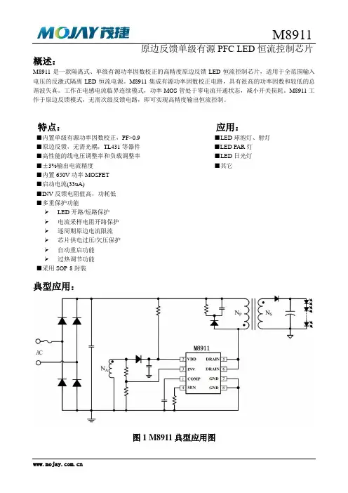
概述:M8911是一款隔离式、单级有源功率因数校正的高精度原边反馈LED恒流控制芯片,适用于全范围输入电压的反激式隔离LED恒流电源。
M8911集成有源功率因数校正电路,具有很高的功率因数和较低的总谐波失真。
工作在电感电流临界连续模式,功率MOS管处于零电流开通状态,减小开关损耗。
M8911工作于原边反馈模式,无需次级反馈电路,即可实现高精度输出恒流控制。
特点:应用:■内置单级有源功率因数校正,PF>0.9 ■LED球泡灯、射灯■原边反馈,无需光耦,TL431等器件■LED PAR灯■高性能的线电压调整率和负载调整率■LED日光灯■±3%输出电流精度■其它■内置650V功率MOSFET■启动电流(33uA)■INV反馈电阻值高,功耗低■多重保护功能LED开路/短路保护电流采样电阻开路保护逐周期原边电流限流芯片供电过压/欠压保护自动重启功能过热调节功能■采用SOP-8封装典型应用:图1 M8911典型应用图管脚排列图:M8911图2 M8911管脚排列图管脚描述:极限参数:推荐工作范围:但并不完全保证满足个别性能指标。
电气参数定义了器件在工作范围内并且在保证特定性能指标的测试条件下的直流和交流电参数规范。
对于未给定上下限值的参数,该规范不予保证其精度,但其典型值合理反映了器件性能。
注2:温度升高最大功耗一定会减小,这也是由TJMAX, θJA,和环境温度TA所决定的。
最大允许功耗为PDMAX= (TJMAX-TA)/ θJA或是极限范围给出的数字中比较低的那个值。
注3:人体模型,100pF电容通过1.5KΩ电阻放电。
电气参数:Tc=25℃注4:典型参数值为25˚C下测得的参数标准。
注5:规格书的最小、最大规范范围由测试保证,典型值由设计、测试或统计分析保证。
芯片内部结构框图:图3 M8911内部框图应用信息M8911是一款隔离式、原边反馈、单级有源功率因数校正LED恒流控制芯片,工作在电感电流临界连续模式,芯片可以实现很高的功率因数和高效率。
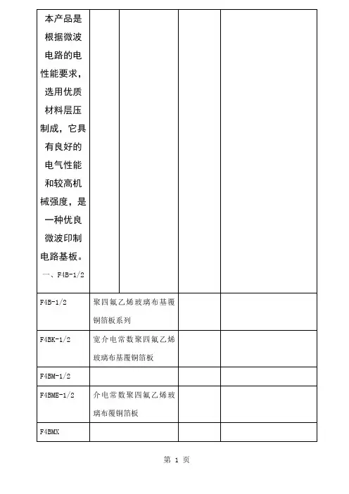
二、F4BK-1/2技术条件
本产品是采用玻璃布和聚四氟乙烯树脂经科学配制和严格工艺压制而成。
其电气性能比F4B系列有一定提高,主要体现在介电常数范围更宽。
三、F4BM系列
产品是采用玻璃布、半固化片和聚四氟乙烯树脂经科学配制和严格工艺压制而成。
其电气性能比F4B系列有一定提高,主是介电常数范围更宽,介质损耗角正切值低、电阻值增大、性能更稳定。
四、F4BME-1/2
本产品是采用纯进口玻璃漆布、半固化片和聚四氟乙烯树脂经科学配制和严格工艺压制而成。
其电气性能比F4BM有一定提高,并增加了无源互调指标。
希望以上资料对你有所帮助,附励志名言3条:
1、宁可辛苦一阵子,不要苦一辈子。
2、为成功找方法,不为失败找借口。
3、蔚蓝的天空虽然美丽,经常风云莫测的人却是起落无从。
但他往往会成为风云人物,因为他经得起大风大浪的考验。
DSJ80/40/2×55型伸缩带式输送机使用维护说明书执行标准:MT820—2006《煤矿用带式输送机技术条件》 MT/T901—2000《煤矿井下用伸缩带式输送机》目录第一章概述 (4)1.1 用途和特性 (4)1。
2型号编制说明 (5)1.3 使用环境及工作条件 (5)第二章相关设计计算 (6)2。
1 已知条件 (6)2.2 初定设计参数 (6)2。
2。
1 输送能力验算 (6)2。
2.2 输送线路设计 (7)2.2。
3 驱动力的计算 (7)2.2.4 传动功率的计算 (8)2。
2.5 输送带张力计算 (8)第三章工作原理及主要部件结构特点 (12)3。
1 工作原理 (12)3.2 结构概述 (12)3.2.1机头传动装置 (12)3.2.2贮带装置 (14)3.2.3 张紧装置 (15)3.2.4 收放胶带装置 (15)3.3 非固定部分 (15)3.3。
1中间支架 (15)3.3.2机尾 (16)3.4综合保护装置 (16)第四章安装、调正与试运转 (17)4。
1安装 (17)4。
2调正 (17)第五章操作 (18)5。
1后退式 (19)5。
2 前进式 (19)第六章维护、修理及警示 (20)6.1 维护及修理 (20)6.2 警示 (21)第一章概述1.1 用途和特性伸缩带式输送机主要用于综合机械化采煤工作面的顺槽运输,也可用于一般采煤工作面的顺槽运输和巷道掘进运输。
用于顺槽运输时,尾端配刮板输送机与工作面运输机相接;用于巷道掘进运输时,尾端配胶带转载机与掘进机相接。
伸缩带式输送机的主要特征:1、除转载机与机尾有一搭接长度可供工作面快速推进外,通过收放胶带装置和贮带装置也可使机身得到伸长和缩短,从而能较有效地提高顺槽运输能力,加快回采和掘进进度。
2、非固定部分的机身,采用无螺栓连接的快速可换支架,结构简单,拆装方便,劳动强度低,操作时间短。
3、设备在机身固定部分的胶带张紧装置采用电绞车拖动代替人工张紧。
数码管WSLED4使用说明书--V1.1产品目录第一章产品概述及展示 (1)1.1产品概述 (1)1.2产品展示 (1)第二章产品接线说明 (2)2.1脚位定义 (2)2.2与PLC连接方式 (2)第三章产品操作 (3)3.1修改D寄存器的值 (3)3.2修改显示D寄存器地址 (3)第四章简易文本PLC占用资源举例 (3)第五章PLC部分说明 (4)第六章常见故障 (4)第一章产品概述1.1产品概述·此款是为了满足要求不高,显示较简单,空间狭小的使用环境而推出的:·操作简单,无需编程,即插即显示;·无需单独供电,直接PLC供电;·四位数码管显示;·功能按键和普通按键功能复用;·电压兼容3.3V-5V;·可以修改显示或写入地址;·开机后5秒无通讯,显示NO PLC。
1.2产品展示正面背面图1-1图1-2第二章产品接线说明2.1脚位定义,如图示:图2-12.2与PLC 连接方式:2.2.1TTL 直接连接直接连接((我们有专门的板直接配这样的线我们有专门的板直接配这样的线,,直接连接即可直接连接即可,,见下图见下图););图2-2图2-3第三章产品操作3.1修改D寄存器的值【1】正常模式下长按SET键5秒直到第一位上字符闪烁,即可修改当前值;【2】按UP为增加D寄存器的值,长按数值快速增加,间断按数值缓慢增加;按DOWN为减少D寄存器的值。
长按数值快速减少,间断按数值缓慢减少。
【3】再按ENT,修改完毕,退出。
3.2修改显示D寄存器地址:【1】上电默认显示和修改D110的值,可以设置为显示和修改为其它寄存器的值【2】操作方法:先按住SET键和ENT键,然后上电,并持续按住3秒以上,进入设置寄存器模式。
【3】按下SET键即可进行显示D寄存器地址的修改,修改时按UP,DOWN更改寄存器地址,数码管修改完成后按ENT切换修改下排数码管。
MGate5119系列1埠DNP3/IEC101/IEC104/Modbus轉IEC61850閘道器特色與優點•支援IEC61850MMS伺服器•支援DNP3串列/TCP主控裝置•支援IEC60870-5-101主控裝置(平衡/非平衡)•支援IEC60870-5-104用戶端•支援Modbus RTU/ASCII/TCP主控裝置/用戶端•嵌入式流量監控/診斷資訊,便於故障排除•輕鬆佈線的內建乙太網路串接•-40°C至75°C操作溫度範圍•串列內建埠2kV隔離保護•支援IEC61850MMS和DNP3TCP通訊協定加密•基於IEC62443/NERC CIP的安全功能•符合IEC61850-3和IEEE1613•內建SCL檔案產生器,便於配置認證簡介MGate5119是工業乙太網路閘道器,具有2個乙太網路連接埠和1個RS-232/422/485串列埠。
若要將Modbus、IEC60870-5-101和IEC60870-5-104裝置與IEC61850MMS網路相整合,請將MGate5119做為Modbus主控裝置/用戶端、IEC60870-5-101/104主控裝置和DNP3串列/TCP主控裝置,藉以收集資料並與IEC61850MMS系統交換資料。
透過SCL產生器輕鬆配置MGate5119做為IEC61850MMS伺服器,通常需要匯入由第3方工具產生的SCL檔案。
這可能很耗時,而且會增加成本。
為了克服這個難處,MGate 5119內建SCL產生器,可以透過Web主控台輕鬆產生SCL檔案並幾乎立即可用,因此節省配置時間和成本。
透過流量監視器輕鬆進行故障排除MGate5119系列閘道器支援Modbus RTU/ASCII/TCP、IEC60870-5-101、IEC60870-5-104和IEC61850MMS通訊協定流量監控,故障排除更容易,特別在安裝階段。
值得一提的是,可以在常用的故障排除工具Wireshark中查看流量日誌。
版本记录销售与服务广州大彩光电科技有限公司电话:************-601传真:************Email:*************(咨询和支持服务)网站:地址:广州黄埔区(科学城)玉树华新园C栋3楼网络零售官方旗舰店:目录1. 硬件介绍 (1)1.1产品外观 (1)1.2硬件配置 (1)1.3调试工具 (2)2. 安装示意图 (3)3. 产品规格 (4)4. 可靠性测试 (7)4.1ESD测试 (7)4.1.1执行标准 (7)4.1.2测试环境 (7)4.1.3测试数据 (7)4.2高低温老化测试 (8)4.2.1测试环境 (8)4.2.2测试数据 (8)4.3群脉冲测试 (9)4.3.1执行标准 (9)4.3.2测试环境 (9)4.3.3测试数据 (9)4.4辐射测试 (9)4.4.1执行标准 (9)4.4.2测试环境 (9)4.4.3测试数据 (10)5. 产品尺寸 (12)6. 型号定义 (13)7. RS232与TTL电平转换 (14)8. 协议配置 (15)9. LUA脚本配置 (16)10. 包装与物理尺寸 (17)11. 产品架构 (18)12. 开发软件 (19)12.1什么是虚拟串口屏 (19)12.2Keil与虚拟串口屏绑定调试 (20)13. 开发文档 (21)14. 免责声明 (22)1. 硬件介绍本章节主要介绍产品的一些外观参考图、硬件配置图和调试所需工具。
1.1 产品外观以下为该尺寸的外观参考图,如图1-1所示。
注:未涉及关键结构工艺修改或布局大调整,仅产品工艺或可靠性方面的变更迭代,公司不予对外发起变更,具体以收到的实物为准。
图1-1 21.5寸电容触摸参考图1.2 硬件配置以下为该尺寸产品硬件配置参考图,如图1-2所示。
图1-2硬件配置图1.3 调试工具以下为该产品调试工具参考图,如图1-3所示。
图1-3调试工具图2. 安装示意图以下为该型号产品的安装示意图。
1特点● 单级、有源功率因数校正,高 PF 值,低 THD ● 原边反馈恒流控制,无需次级反馈电路 ● ±5% LED 输出电流精度● 优异的线电压调整率和负载调整率 ● 电感电流临界连续模式● 内置650V 功率 MOSFET ● 超低 (10uA) 启动电流 ● FB 反馈电阻值高,功耗低 ● LED 开路/短路保护 ● 电流采样电阻开路保护 ● 逐周期原边电流限流 ● 芯片供电过压/欠压保护 ● 自动重启功能 ● SOP-8封装● 过热调节温度可以通过外部电阻设定应用● GU10/E27 LED 球泡灯、射灯 ● LED PAR30、PAR38 灯 ● LED 日光灯 ● 其它LED 照明概述M891X 是一款单级、带有源功率因数校正的高精度原边反馈LED 恒流控制芯片,适用于 85Vac-265Vac 全范围输入电压的反激式隔离LED 恒流电源。
M891X 集成有源功率因数校正电路,可以实现很高的功率因数和很低的总谐波失真。
由于工作在电感电流临界连续模式,功率 MOS 管处于零电流开通状态,开关损耗得以减小,同时变压器 的利用率也较高。
M891X 采用专有的电流采样机制,工作于原边反馈 模式,无需次级反馈电路,即可实现高精度输出恒 流控制,节约了系统成本和体积,提高了系统的可靠性。
M891X 采用先进的线电压和负载补偿技术,可以达 到优异的线电压调整率和负载调整率。
线电压补偿系数还可以通过外部元件灵活调整。
M891X 内置多重保护功能来加强系统可靠性,包括 LED 开路保护、LED 短路保护、芯片供电过压保护、 欠压保护、电流采样电阻开路保护和逐周期限流等。
所有的保护都具有自动重启功能。
典型应用NpNs231765VCC FBCOMP Drain GND ACN AUXM891X 84CSRTHDrain2管脚封装CSRTH COMP DRAINVCC FB 123876M891X45DRAIN GND图2 管脚封装图管脚描述 管脚号 管脚名称描述1 COMP 环路补偿点2 VCC 芯片电源3FB 电流采样端,接采样电阻到地 4 CS反馈信号采样端 5,6 DRAIN功率 MOS 管漏极 7 GND 芯片信号和功率地 8RTH温度调节电阻设置点。
后超高端CT设备技术参数要求后超高端CT设备技术参数要求一.概述本次招标采购设备为螺旋CT,投标方应根据招标文件所提出的设备技术规格、产品、产量和服务要求,综合考虑设备和适应性,选择具有最佳性能价格比的设备前来投标。
希望投标方以精良的设备、优良的服务和优惠的价格,充分显示贵公司的竞争实力。
二.招标货物一览表设备用途可用于神经系统、消化系统、心血管系统、泌尿生殖系统、脊柱脊髓系统、骨关节系统的计算机断层成像,并可为临床提供先进的能谱成像、灌注等功能分析,以满足医院全身CT扫描的临床应用和临床研究。
三.设备技术要求及相应配置招标要求一、总体要求 1 国家医疗器械注册证(CFDA)各公司提供符合标书要求的最新款CT设备 2 投标机型要求单源≥256排或双源≥192排多排螺旋CT,具备宽体、快速、能谱、超低剂量、高清等功能。
二、主要参数 1 机架*1.1 机架孔径≥79cm 1.2 球管焦点到探测器距离≥109cm 1.3 球管焦点到等中心点距离≥62cm 1.4 机架旋转驱动系统静音电磁直接驱动 1.4.1 滑环类型无接触静音滑环 1.4.2 滑环数据传输方式射频信号传递 1.4.3 滑环数据传输速度≥40Gbps 1.5 机架内部冷却方式风冷或者水冷 1.6 机架内置病人信息显示装置数量具备12寸液晶屏显示2个1.7 机架内置心电图显示装置具备 1.8 机架控制面板数量≥4个 1.9 机架激光定位灯精度≤± 1 mm 2 X线部分 2.1 高频逆变式高压发生器2.1.2 高压发生器功率≥103KW 2.1.3 输出管电压档位≥ 5档*2.1.4 最小输出管电压范围≤70KV 2.1.5 具备高压发生器瞬时变能功能具备 2.1.6 系统具备能谱成像的能力,从而能够实现原始投影数据空间进行能谱解析的能力具备2.1.7 系统在进行最快能量时间分辨率下,能谱扫描时FOV ≥50cm 2.2 球管 2.2.1 球管热容量≥6.5MHU或性能相当的低热容量高散热率球管 2.2.2 球管最大散热率≥3 KW 2.2.3 球管冷却方式风冷和油冷 2.2.4 最高输出管电流≥700mA 2.2.5 最低输出管电流≤10mA 2.2.6 球管焦点调整方式动态变焦2.2.7 球管支持高低压瞬时切换功能具备;能够在高压140KV和低压80KV进行瞬时切换,双能量曝光和切换的周期不大于0.25毫秒(提供原版技术白皮书,技术白皮书须对此功能进行详细描述)2.3 探测器*2.3.1 探测器Z轴物理排列探测器Z轴物理排列单源≥256排及以上,双源探测器≥192排;*2.3.2 探测器Z轴物理宽度≥16cm 2.3.3 探测器Z轴排列模式等焦点设计或球面探测器设计2.3.4 探测器单元总数210,000个2.3.5 探测器材料请提供探测器材料的专用技术白皮书,对探测器材质、性能、参数有详细描述 2.3.6 探测器材质初始速度≤0.03μ 2.3.7 探测器材质余晖效应≤0.001% 2.3.8 探测器材质稳定度放射损害(Radiation Damage)≤0.03 2.3.9 探测器数据采集系统DAS 设计模式芯片式高集成化设计 2.3.10 探测器数据采集系统DAS电子噪声210,000个通道 2.3.12 探测器数据采集系统DAS数据采样率≥8914Hz 2.3.13 CT系统后准直器设计方法具备3D后准直器,能够阻挡X/Y和Z轴方向的散射线,并对X线入射探测器单元进行精确制导具备 2.4 扫描床2.4.1 扫描床水平移动范围≥2000mm 2.4.2 扫描床最大无金属可扫描范围≥2000mm 2.4.3 扫描床最大水平移动速度≥300mm/秒2.4.4 扫描床垂直升降可低至≤50cm 2.4.5 扫描床垂直升降最高≥100cm 2.4.6 扫描床精度最大承重≥227KG 2.4.7 扫描床最大承重下的定位精度±0.25mm 2.4.8 在垂直位置上,床可以自动回复到中心平面具备 2.4.9 扫描床控制脚踏开关具备 2.5 主控制台 2.5.1 主控台计算机注明计算机型号2.5.2 计算机主频≥82.66 GHz 2.5.3 计算机内存≥64GB DDR3 2.5.4 图像存储硬盘容量≥1 TB 2.5.5 图像存储量≥700,000幅(512X512不压缩)2.5.6 原始数据存储量≥1,500 个检查 2.5.7 主控计算机软件编码平台Red Hat Enterprise Linux或者win7 2.5.8 主控计算机软件编码平台位数64 bit 2.5.9 医学专用液晶超薄平面显示器尺寸≥24寸2.5.10 医学专用液晶超薄平面显示器个数≥2 个2.5.11 医学专用液晶超薄平面显示器分辨率≥1920*1200 2.5.12 支持CD读取和刻录支持2.5.13 用户操作界面图文可视化操作见面2.5.14 具备多窗口Multi-Tab多任务处理Multi-tasking 功能具备2.5.15 对比剂智能跟踪和启动扫描功能具备 2.5.16 并行重建功能并行处理多种模式的图像的重建与重组,可以在一个扫描方案中预置和完成不同算法的重建任务2.5.17 同步并行处理功能扫描、重建、显示、存储、打印等操作可同步进行 2.5.18 双向交流系统自动病人呼吸屏气辅助控制系统,双向语音传输,并且可用户录制病人呼吸指令 2.5.19 DICOM3.0 提供DICOM3.0激光相机接口(传输/接收/打印/存档/查询/工作表等) 2.5.20 低剂量管理功能 2.5.21 扫描剂量预估功能具备 2.5.22 剂量报告功能具备 2.5.23 扫描剂量智能监控预警平台具备2.5.24 3D自动mA功能具备2.5.25 自动kV功能具备,根据定位相自动推荐最佳kV和mA *2.5.26 儿科70kV超低剂量功能具备 2.5.27 动态灌注超低剂量功能具备 2.5.28 敏感器官自动保护功能具备 2.5.29 Color Coding for Kids 儿童彩色编码系统具备 2.5.30 螺旋扫描起始段剂量智能阻挡功能具备 2.5.31 宽体容积高清重建算法具备 2.5.32 宽体容积支持轴扫最大Z轴探测器物理准直宽度≥16cm 2.5.33 宽体容积支持螺旋扫描最大Z轴探测器物理准直宽度≥8cm 2.5.34 全模型实时迭代重建算法具备,GE必须提供ASiR-V,西门子必须提供ADMIRE,东芝必须提供FIRST 2.5.35 全模型实时迭代重建算法的效能检测得到FDA的认证具备 2.5.36 全模型实时迭代重建算法可以降低X线辐射剂量Dose Reduction的效能≥82 2.5.37 全模型实时迭代重建算法可以提高图像密度分辨率Low Contrast Detectability的效能≥135 2.5.38 全模型实时迭代重建算法可以降低图像噪音Image Noise Reduction的效能≥91 2.5.39 全模型实时迭代重建算法的重建速度≥25 frames per second 2.6 扫描参数 2.6.1 轴扫最大Z轴覆盖范围≥16cm/ 360° 2.6.2 轴扫每圈图象采集数单源≥512层/ 360°2.6.3 电影扫描(Cine mode的最大Z轴覆盖范围≥16cm/ 360° 2.6.4 螺旋扫描最大准直器Z轴覆盖范围≥8cm 2.6.5 单次螺旋连续扫描时间≥60秒 2.6.6 螺旋扫描螺距范围0.5081 - 1.51,多级可调 2.6.7 定位像最大长度≥1900mm 2.6.8 最快机架旋转速度≤0.28sec/360° 2.6.9 最快有效单扇区时间分辨率≤29ms/360° 2.6.10 最薄图像扫描层厚≤0.625mm 2.6.11 能谱最快时间分辨率下最大扫描FOV ≥50cm 2.6.12 最大DFOV ≥50cm 2.6.13 图像重建矩阵≥ 512 x 512 2.6.14 图像显示矩阵≥1024*1024 2.6.15 最小CT值(非扩展CT值)≤ -1024 HU 2.6.16 最大CT值(非扩展CT值)≥ 3071 HU 2.6.17 最小扩展CT值≤ -31743 HU 2.6.18 最大扩展CT值≥ 31743 HU 2.6.19 70kV轴扫及螺旋扫描功能 2.7 图像质量 2.7.1 各相同性分辨率≤0.23 mm (请提供技术白皮书,技术白皮书须对此参数进行详细描述) 2.7.2 Z轴空间分辨率MTF10 ≥18 lp/cm (请提供技术白皮书,技术白皮书须对此参数进行详细描述,不能以其他MTF条件的参数替代)2.7.3 低对比度分辨率用5mm体模测量5mm0.3, 5mm 重建层厚≤24 mGy CTDI vol (请提供技术白皮书,技术白皮书须对此功能进行详细描述,不能以其他条件的参数替代)2.7.4 低对比度分辨率用3mm体模测量3mm0.3, 5mm 重建层厚≤24 mGy CTDI vol (请提供技术白皮书,技术白皮书须对此功能进行详细描述,不能以其他条件的参数替代)2.8 心脏成像功能 2.8.1 心脏扫描时间有效单扇分辨率≤29ms(提供技术白皮书) 2.8.2 心电监护系统具备2.8.3 ECG实时监测具备2.8.4 ECG自动毫安调控功能具备2.8.5 单心动周期ECG自动毫安调控功能具备 2.8.6 单心动周期ECG自动毫安调控功能可进行调控的期相最大数量≥3 个期相 2.8.7 不受心率和心律限制的前门控轴扫技术具备 2.8.8 不受心率和心律限制的单次心动周期冠脉成像技术具备 2.8.9 房颤病人的单心动周期冠脉成像技术具备 2.8.10 不受心率和心律限制的单次心动周期心功能成像具备。