三洋步进电机【SANYO】二相42系列说明书(精)
- 格式:doc
- 大小:117.00 KB
- 文档页数:3

合肥荣事达三洋电器股份有限公司洗衣机维修手册2003年11月17日洗衣机的故障诊断异常情况发生时,修理之前需要了解以下日常检查注意事项情况:全自动洗衣机症状日常检查注意事项不运转●保险丝是否损坏、保险丝盒是否接触不良?●电源线插头是否插好?●水龙头是否打开?不排水●排水软管是否放下?●排水软管是否堵塞?(如插到地漏底部堵塞?)●排水软管是否接好?不进水● 水龙头是否打开?● 水管是否冻结?● 进水管口/进水阀过滤网是否堵塞?不脱水● 洗涤衣物是否偏置?● 排水软管是否放下?● 洗涤上盖是否没有合上?维修更换部件原则:更换部件必须先从价值低的部件更换,以免进一步扩大维修损失。
全自动洗衣机故障诊断XQB45-428,XQB46-366,XQB45-438,XQB46-376,XQB45-448,XQB46-128,XQB48-628,XQB46-148,XQB48-648,XQB50-149,XQB50-356,XQB46-138,XQB48-668,XQB46-328,XQB50-68,XQB50-98,XQB50-218,XQB50-78,XQB50-168,XQB50-158,XQB50-238,XQB50-258,XQB52-338,XQB52-348,XQB55-118,XQB55-118A,XQB55-268S,XQB60-228S,XQB60-88,XQB60-88A,XQB65-888,XQB70-388,XQB80-8S,XQB80-8SA※1、XQB45-448,46-138,48-668XQB52-338,52-348,55-118XQB80-8S,80-8SA2、XQB50-78、XQB50-168、XQB60-88 3、XQB45-428,46-366,45-438XQB80-8S,XQB80-8SA※1、XQB45-448,46-138,48-668XQB52-338,52-348,55-118XQB80-8S,80-8SA2、XQB45-428,46-366,45-438XQB80-8S,XQB80-8SA※1、XQB45-448,46-138,48-668XQB52-338,52-348,55-118XQB80-8S,80-8SA2、XQB45-428,46-366,45-438XQB80-8S,XQB80-8SA1、进水异常:水位指示发光管表示:⑴XQB60-88、XQB60-88A、XQB65-888、XQB80-8S(全自动侧):高、低、极少点亮⑵XQB45-448、XQB46-138、XQB48-668、XQB50-68、XQB50-78、XQB50-98、XQB50-218 、XQB50-158、XQB50-168、XQB50-238、XQB50-258、XQB55-118、XQB55-118A:高、低、少量点亮程序指示发光管表示:⑴XQB46-148、XQB48-648、XQB50-149、XQB50-356:快洗、浸泡、轻洗、毛毯点亮⑵XQB46-128、XQB48-628:快洗、轻洗、毛毯点亮⑶XQB45-428、XQB46-366、XQB45-438、XQB46-376:浸泡、轻洗、毛毯、快洗点亮分洗侧发光管表示:⑴XQB80-8S(分洗侧):12、6、3+补给水或精漂、标准、节约+补给水点亮⑵XQB80-8SA(分洗侧):12、6、3点亮数码管表示:⑴XQB46-328、XQB52-338、XQB52-348、XQB55-268S、XQB60-228S、XQB70-388、XQB80-8SA(全自动侧):E1显示2、排水异常:水位指示发光管表示:⑴XQB60-88、XQB60-88A、XQB65-888、XQB80-8S(全自动侧):高、中、极少点亮⑵XQB45-448、XQB46-138、XQB48-668、XQB50-68、XQB50-78、XQB50-98、XQB50-218 、XQB50-158、XQB50-168、XQB50-238、XQB50-258、XQB55-118、XQB55-118A:高、中、少量点亮⑶XQB45-428、XQB46-366、XQB45-438、XQB46-376:标准、轻洗、毛毯、快洗点亮程序指示发光管表示:⑴XQB46-148、XQB48-648、XQB50-149、XQB50-356:快洗、标准、轻洗、毛毯点亮⑵XQB46-128、XQB48-628:标准、轻洗、毛毯点亮分洗侧发光管表示:⑴XQB80-8S(分洗侧):12、6、3+排水或精漂、标准、节约+排水点亮⑵XQB80-8SA(分洗侧):精漂、标准、节约点亮数码管表示:⑴XQB46-328、XQB52-338、XQB52-348、XQB55-268S、XQB60-228S、XQB70-388、XQB80-8SA(全自动侧):E2显示3、脱水异常:水位指示发光管表示:⑴XQB60-88、XQB60-88A、XQB65-888、XQB80-8S(全自动侧):高、中、低点亮⑵XQB45-448、XQB46-138、XQB48-668、XQB50-68、XQB50-78、XQB50-98、XQB50-218 、XQB50-158、XQB50-168、XQB50-238、XQB50-258、XQB55-118、XQB55-118A:高、中、低点亮⑶XQB45-428、XQB46-366、XQB45-438、XQB46-376:标准、浸泡、毛毯、快洗点亮程序指示发光管表示:⑴XQB46-148、XQB48-648、XQB50-149、XQB50-356:快洗、标准、浸泡、毛毯点亮⑵XQB46-128、XQB48-628:标准、快洗、毛毯点亮数码管表示:⑴XQB46-328、XQB52-338、XQB52-348、XQB55-268S、XQB60-228S:U3显示——衣物偏置、机器不平?⑵XQB46-328、XQB52-338、XQB52-348、XQB55-268S、XQB60-228S、XQB70-388:U4显示——洗涤上盖打开?⑶XQB80-8SA(全自动侧):E3显示——衣物偏置、机器不平?⑷XQB80-8SA(全自动侧):E4显示——洗涤上盖打开?4、水位传感器异常:水位指示发光管表示:⑴XQB60-88、XQB60-88A、XQB65-888:中、低、极少点亮⑵XQB45-448、XQB46-138、XQB48-668、XQB50-68、XQB50-78、XQB50-98、XQB50-218 、XQB50-158、XQB50-168、XQB50-168、XQB50-238、XQB50-258、XQB55-118、XQB55-118A、XQB80-8S(全自动侧):中、低、少量点亮数码管表示:⑴XQB46-328、XQB52-338、XQB52-348、XQB55-268S、XQB60-228S、XQB70-388、XQB80-8SA(全自动侧):EA显示5、其它异常:程序指示发光管表示:⑴XQB46-148、XQB48-648、XQB50-149、XQB50-356:快洗、标准、浸泡、轻洗点亮——电脑板电源损坏?⑵XQB45-428、XQB46-366、XQB45-438、XQB46-376:标准、浸泡、轻洗、快洗点亮——洗涤中断?⑶XQB46-128、XQB48-628:标准、快洗、轻洗点亮——洗涤上盖打开?数码管表示:⑴XQB46-328、XQB52-338、XQB52-348、XQB55-268S、XQB60-228S、XQB70-388:EC显示——负载检测异常?数码管表示:⑴XQB46-328、XQB52-338、XQB52-348、XQB55-268S、XQB60-228S、XQB70-388:U5显示——儿童锁设置?1、后板的拆装方法:a.取下进水阀盖/烘干口塑贴/烘干口盖b.松开后板紧固螺钉,拆下后板。

IntroductionASASC5-Phase Microstep RK 2-Phase Full/Half UMK 5-PhaseMicrostep CRK 2-Phase Microstep RBK 2-Phase Microstep CMK 2-Phase PK/PV 2-Phase PK EMP400SG8030J AccessoriesInstallationAC InputDC InputAC InputDC Input Without Encoder With EncoderControllersConnection and Operation■Names and Functions of Driver Parts●(Top)□2 Function Switches □1 Signal Monitor Displays◇Alarm◇(Front)□3 Motor Run Current Switch □4 Step Angle Setting Switch □1 Signal Monitor Displays □5 Input/Output Signals Motor TerminalsPower Input TerminalsProtective Earth TerminalsThe step angle set with the step angle setting switch will become effective when the "Step●Angle Select" (CS) signal input is OFF.Do not change the "Step Angle Select" (CS) signal input or step angle setting switch while ●the motor is operating. It may cause the motor to misstep and stop. Change the step angle setting switch, when the "Step Angle Select" (CS) signal input is OFF and the "Excitation Timing" (TIM) signal output is ON.The cable for connecting the terminal box type motor and driver, and the D-Sub (15-pin) connector for connecting to the driver's CN1 connector are not included. They must be supplied separately. ✽Description of input/output signals ➜ Page C-177Connection Diagrams●5 VDC Connection or Line Driver Input◇DriverController24 VDC Connection◇DriverInput Signal Connection◇Pulse (PLS) Signal, Rotation Direction (DIR) Signal●You can select either 5 VDC or 24 VDC as the signal voltage. Line driver input is also available. The pin No. to connect differs according to the signal voltage.All Windings Off Signal, Step Angle Select Signal●You can select either 5 VDC or 24 VDC as the signal voltage. The pin No. to connect is the same for 5 VDC and 24 VDC.Output Signal Connection◇Keep the output signal voltage and current below 30 VDC and 10 mA respectively.Power Supply◇Use a power supply that can supply sufficient input current. When power supply capacity is insufficient, a decrease in motor output can cause the following malfunctions: Motor does not operate properly at high-speed. ●Slow motor startup and stopping.●Notes on Wiring◇Use twisted-pair wires of AWG26 and keep wiring as short as possible [within 2 m (6.6 ft.)]. ●Note that as the length of the pulse signal line increases, the maximum transmission ●frequency decreases. Technical reference ➜ Page F-54Use wires of AWG18 or thicker for motor lines (when extended), power supply lines and ●protective earth line.To ground the driver, lead the ground conductor from the protective earth terminal (M4) and ●connect the ground conductor to provide a common ground point.Signal lines should be kept at least 2 cm (0.79 in.) away from power lines (power supply lines ●and motor lines). Do not bind the signal lines and power lines together.If noise generated by the motor cable or power cable becomes a problem due to the wiring ●and layout, shield the cables or use ferrite cores.Incorrect connection of DC power input will lead to driver damage. Make sure that the polarity ●is correct before turning power on.The cable for connecting the terminal box type motor and driver, and the D-Sub (15-pin) ●connector for connecting to the driver's CN1 connector are not included. They must be supplied separately.●Driver Motor Terminals and Motor Leads/Motor Terminal BlocksTerminal Box Type Motor Connections ◇RBK264T , RBK266T ,RBK268T∼16)[Diameter: (ϕ0.28∼ϕ0.51 in.)]✽ (M4)InternalTerminal ✽ (M4)(AWG18 or thicker)(AWG18 or thicker)Connect motor lead wires to the terminals 2 to 5.12345Terminal BlockConnect either the internal protective earth terminal or external protective earth terminal to the ground.✽RBK296T , RBK299T , RBK2913T✽ (M4)∼16)InternalTerminal ✽ (M4)[Diameter: ϕ7(ϕ0.28∼ϕ0.51 in.)](AWG18 or thicker)54123678Connect either the internal protective earth terminal or external protective earth terminal to the ground.✽Terminals 1, 4, 5, and 8 are used. Terminals 2, 3, 6, and 7 are not used. Do not connect anything to them.IntroductionASASC5-Phase Microstep RK 2-Phase Full/Half UMK 5-Phase Microstep CRK2-Phase Microstep RBK 2-Phase Microstep CMK 2-Phase PK/PV 2-Phase PK EMP400SG8030J Accessories InstallationAC InputDC InputAC InputDC InputWithout Encoder With EncoderControllersPulse (PLS), Rotation Direction (DIR) Input SignalYou can select either 5 VDC or 24 VDC as the signal voltage for"Pulse" input and "Rotation Direction" input. Line driver input is also available.Input Circuit and Sample Connection ◇5 VDC Connection●24 VDC Connection●Line Driver Input●Pulse Waveform Characteristics ◇5 VDC or 24 VDC Connection●ONON Pulse Input SignalRotation Direction Input Signal 1 Pulse duty: 50% and belowLine Driver Input●ONON Pulse Input SignalRotation Direction Input Signal 1 Pulse duty: 50% and below1 ✽ The shaded area indicates when the photocoupler diode is ON. The motor moves when thephotocoupler state changes from ON to OFF.2 ✽ The minimum interval time when changing rotation direction is 10 μs. This value variesgreatly depending on the motor type, pulse frequency and load inertia.Pulse Signal Characteristics◇Keep the pulse signal at the "photocoupler OFF" state when no ●pulses are being input.Leave the pulse signal at rest ("photocoupler OFF") when ●changing rotation directions.All Windings Off (AWO), Step Angle Select (CS) Input Signal Input Circuit and Sample Connection◇All Windings Off (AWO) Input Signal◇Inputting this signal puts the motor in a non-excitation (free) state. ●This signal is used when turning the motor by external force or ●manual home position is desired. The photocoupler must be "OFF" when operating the motor.ON OFFAll Windings Off Input Signal Motor CurrentMotor Holding TorqueThe shaded area indicates that the motor provides holding torque in proportion to standstill current set by motor stop current switch.Switching the "All Windings Off" signal from "photocoupler ON" to ●"photocoupler OFF" does not alter the excitation sequence. When the motor shaft is manually adjusted with the "All Windings Off" signal input, the shaft will shift up to ±3.6° from the position set after the "All Windings Off" signal is released.Step Angle Select (CS) Input Signal◇When this signal input is "ON," the motor will operate at the basic ●step angle regardless of the settings of the step angle settingswitches. When the signal input is "OFF ," the motor will operate at the step angle set with the step angle setting switch.To change the step angle, do so when the "Excitation Timing" ●signal output is "ON" and the motor is at standstill.Current Cutback (CD), Alarm (ALM), Excitation Timing (TIM) Output SignalOutput Circuit and Sample Connection◇Current Cutback (CD) Output Signal◇When the automatic current cutback function is activated, the ●"Current Cutback" output turns on.Alarm (ALM) Output Signal◇When the motor is running, if the driver overheat, overvoltage, or ●overcurrent protective function is detected, the "Alarm" output turns off, and the ALARM LED of the driver flashes. The current to the motor is also cut off to stop the motor.You can count the number of times the ALARM LED flashes to ●confirm which protective function is activated.This signal normally stays on, but turns off when a protective ●function is activated.Excitation Timing (TIM) Output Signal◇The "Excitation Timing" signal is output to indicate when the motor ●excitation is in the initial stage (step "0" at power up).The "Excitation Timing" signal is output simultaneously with a ●pulse input each time the excitation sequence returns to step "0." The excitation sequence will complete one cycle for every 7.2˚ rotation of the motor output shaft.Microsteps/step 1: S ignal is output once every 4 pulses.Microsteps/step 4: S ignal is output once every 16 pulses.Timing chart at 1.8/step (Microsteps/step 1)When connected as shown in the sample connection, the signal will be ✽"photocoupler ON " at step "0."Pulse Input Rotation Direction Input Excitation Timing Output ✽12345678910(Step)01230123012321011121314Notes:When power is turned ON, the excitation sequence is reset to step "0" and the "Excitation ●Timing" signal is output.When operating the motor using the ●"Excitation Timing " signal output, make sure the motor output shaft stops at an integral multiple of 7.2˚.Timing Chart●Rotation Direction Input Signal Pulse Input Signal All Windings Off Input Signal Step Angle Select Input Signal Current Cutback Output Signal MotorPower Input The section indicates that the photocoupler diode is emitting light.1 ✽ The minimum switching time to change direction 10 μs isshown as the response time of the circuit. The motor may need more time than that.2 ✽ Depends on load inertia, load torque, and starting frequency.3 ✽ Never input a pulse signal immediately after switching the"All Windings Off " signal to the "photocoupler OFF" state. The motor may not start.4 ✽ To cycle the power, turn off the power and then wait for atleast five seconds after the POWER LED has turned off.。

FixedSeries LEPY/LEPSSpecific Product Precautions 1Be sure to read before handling. Refer to back cover for Safety Instructions and the Operation Manual for Electric Actuator Precautions. Please download it via our website, 20C o u r t e s y o f C M A /F l o d y n e /H y d r a d y n e ŀ M o t i o n C o n t r o l ŀ H y d r a u l i c ŀ P n e u m a t i c ŀ E l e c t r i c a l ŀ M e c h a n i c a l ŀ (800) 426-5480 ŀ w w w .c m a f h .c o m7.When it is necessary to operate the product by the manual override screw, check the position of the manual override and leave necessary space for access.Do not apply excessive torque to the manual override screw. This may lead to damage and malfunction.8.When an external guide is used, connect it in such a way that no impact or load is applied to it.This may cause a malfunction due to an increase in sliding resistance, or use a freely moving connector (such as a floating joint).1.When the pushing operation is used, be sure to set to [Pushing operation].Also, do not hit the workpiece in positioning operation or in the range of positioning operation.I t may damage and malfunction. If the operation is interrupted or stopped during the cycle: W hen the pushing operation command is output immediately after restarting the operation, the direction of movement depends on the position of restart.e the product within the specified pushing speed range for the pushing operation.It may lead to damage and malfunction.3.For the pushing operation, ensure that the force is applied in the direction of the rod axis.4.The moving force should be the initial value.If the moving force is set below the initial value, it may cause an alarm.5.The actual speed of this actuator is affected by the load.Check the model selection section of the catalog.6.Do not scratch or dent the sliding parts of the rod, by striking or attaching objects.The rod is manufactured to precise tolerances, even a slight deformation may cause malfunction.7.Avoid using the electric actuator in such a way that rotational torque would be applied to the rod.It may cause deformation of the non-rotating sliding part, leading to clearance in the internal guide or an increase in the sliding resistance.Refer to the table below for the approximate values of the allowable range of rotational torque.HandlingCautionMountingWarningSide mounting (Body mounting through-hole)Side mounting (Body tapped)Bottom mounting (Body tapped)Rod side mounting (Rod type only)6.Tighten the mounting screws within the specified torque range.Tightening with higher torque than the specified range may cause malfunction while the tightening with lower torque can cause the displacement of gripping position or dropping a workpiece.Series LEPY/LEPSSpecific Product Precautions 2Be sure to read before handling. Refer to back cover for Safety Instructions and the Operation Manual for Electric Actuator Precautions. Please download it via our website, 21C o u r t e s y o f C M A /F l o d y n e /H y d r a d y n e ŀ M o t i o n C o n t r o l ŀ H y d r a u l i c ŀ P n e u m a t i c ŀ E l e c t r i c a l ŀ M e c h a n i c a l ŀ (800) 426-5480 ŀ w w w .c m a f h .c o mHandlingCaution13.In pushing operation, set the product to a position of atleast 0.5 mm away from a workpiece. (T his position is referred to as a pushing start position.)The following alarms may be generated and operation may become unstable.a. “Posn failed” alarm is generated.The product cannot reach a pushing start position due to variation in the width of workpieces.b. “Pushing ALM” alarm is generated.The product is pushed back from a pushing start position after starting to push.c. “Deviation over flow” alarm is generated.Displacement exceeding the specified value is generated at the pushing start position.14.For the pushing operation, use the product within theduty ratio range below.The duty ratio is a ratio at the time that can keep being pushed.15.When mounting the product, keep a 40 mm or longerdiameter for bends in the cable.MaintenanceWarning1.Ensure that the power supply is stopped and the workpiece is removed before starting maintenance work or replacement of the product.8.Do not operate by fixing the rod and moving the actuatorbody.Excessive load will be applied to the rod, leading to damage to the actuator and reduced the life of the product.9.Return to origin1)Do not apply a load, impact or resistance in addition to the transferred load during return to origin.Additional force will cause the displacement of the origin position since it is based on detected motor torque.2)W hen the return to origin is set with <Basic parameter> [Origin offset], it is necessary to change the current position of the product. Recheck the value of step data.3)It is recommended to set the directions of return to origin and pushing in the same direction in order to enhance the measurement accuracy during pushing operation.10.There is no backlash effect in pushing operation.The return to origin is done by the pushing operation.The position can be displaced by the effect of the backlash during the positioning operation.Take the backlash into consideration when setting the position.11.Do not hit the stroke end except during return to origin.This may damage the inner parts.12.INP output signal1) Positioning operationW hen the product comes within the set range by step data [In position], the INP output signal will turn on.Initial value: Set to [0.50] or higher.2)Pushing operationW hen the effective pushing force exceeds the step data [Trigger LV], the INP output signal will turn on.W hen [Pushing force] setting and [Trigger LV] are set less than [Pushing force], use the product within the specified range of[Pushing force] and [Trigger LV].a)To ensure that the actuator pushes the workpiece with the set [Pushing force], it is recommended that the [Trigger LV]be set to the same value as the [Pushing force].b)If the [Trigger LV] is set lower than the [operation pushing force (current pushing force) for the pushing operation], the pushing force will exceed the trigger LV from the pushing start position and the INP output signal will turn on before pushing the workpiece. Increase the pushing force, or change the work load so that the current pushing force becomes smaller than the trigger LV.Series LEPY/LEPSSpecific Product Precautions 3Be sure to read before handling. Refer to back cover for Safety Instructions and the Operation Manual for Electric Actuator Precautions. Please download it via our website, 22C o u r t e s y o f C M A /F l o d y n e /H y d r a d y n e ŀ M o t i o n C o n t r o l ŀ H y d r a u l i c ŀ P n e u m a t i c ŀ E l e c t r i c a l ŀ M e c h a n i c a l ŀ (800) 426-5480 ŀ w w w .c m a f h .c o m。
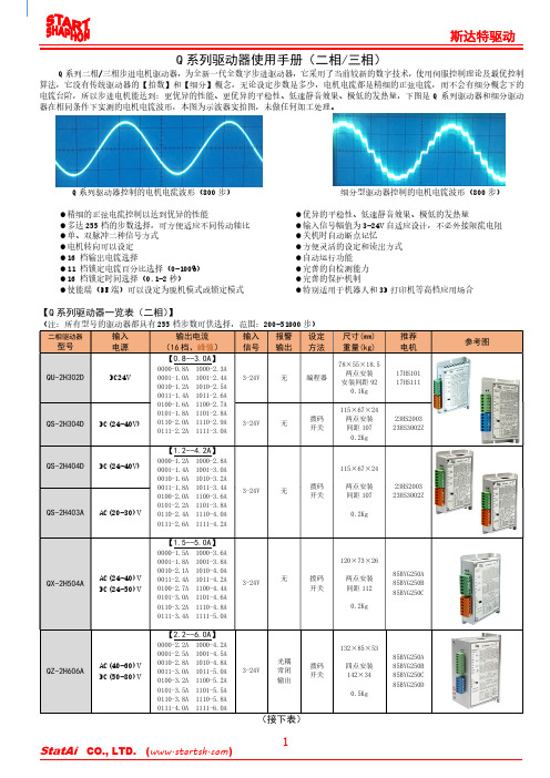
Q 系列二相/三相步进电机驱动器,为全新一代全数字步进驱动器,它采用了当前较新的数字技术,使用伺服控制理论及最优控制电流台阶,所以步进电机能达到:更优异的性能、更优异的平稳性、低速静音效果、极低的发热量,下图是Q 系列驱动器和细分驱动Q 系列驱动器使用手册(二相/三相)算法,它没有传统驱动器的【拍数】和【细分】概念,无论设定步数是多少,电机电流都是精细的正弦电流,而不会有细分概念下的器在相同条件下实测的电机电流波形,本图为示波器实拍图,未做任何加工处理。
Q 系列驱动器控制的电机电流波形(800步) 细分型驱动器控制的电机电流波形(800步)精细的正弦电流控制以达到优异的性能 优异的平稳性、低速静音效果、极低的发热量 多达255档的步数选择,可方便适应不同传动轴比 输入信号幅值为3-24V 自适应设计,不必外接限流电阻 单、双脉冲二种信号方式 关机时自动断点记忆 电机转向可以设定 方便灵活的设定和读出方式 16 档输出电流选择 自动运行功能 11 档锁定电流百分比选择(0-100%) 完善的自检测能力 16 档锁定时间选择(0.1-2秒) 完善的保护机制 使能端(EN 端)可以设定为脱机模式或锁定模式 特别适用于机器人和3D 打印机等高档应用场合【Q 系列驱动器一览表(二相)】(注:所有型号的驱动器都具有255档步数可供选择,范围:200-51000步)(接上表)【Q系列驱动器一览表(三相)】(注:所有型号的驱动器都具有255档步数可供选择,范围:200-51000步) 完全相同,但体积减小便于安装、信号连接方便、有更好的性价比。
此驱动器和本公司切割机控制系统完美结合,驱动器无拨码开关,其参数在系统内设定,驱动器的运行状态被系统时时监测且用于控制。
输入电源:AC(40-70)V,输出电流:2.2-6.0A,机身尺寸:192×120×56,四点安装:302×37,重量:1.0Kg。
步进电机驱动器使用手册目录1安全事项 (2)2产品外形 (4)2.1产品外形 (4)3接口定义 (5)3.1电机、电源接口C N1 (5)3.1.1两相步进电机接线 (5)3.1.2五相步进电机接线 (6)3.2控制接口C N2 (7)3.2.1脉冲(P u l)信号/上限位信号 (9)3.2.2方向(D i r)信号/下限位信号 (9)3.2.3回零(Z e r o)信号/原点信号 (9)3.2.4脱机/使能(F r e e/E n a b l e)信号 (9)3.2.5到位(I N P)信号 (10)3.2.6就绪(R D Y)信号 (11)3.2.7接口电压 (11)3.3编码器接口C N3 (13)3.4U S B接口C N4 (14)3.5M o d b u s接口C N5 (15)4L E D指示 (16)4.1状态指示L E D (16)4.2通讯指示L E D (18)5性能参数 (18)5.1机械参数 (18)5.2安装尺寸 (19)6应用指南 (20)6.1安装准备 (20)6.2机械安装 (20)6.3电气安装 (21)6.4日常维护 (21)6.5注意事项 (21)6.5常见问题 (22)为保障使用者人身安全,保护设备正常使用,请务必阅读并遵守本章的安全事项。
在操作时违反本事项所示要求,可能会导致人员重伤或者死亡。
在操作时违反本事项所示要求,可能会引起驱动器永久损坏及附加事故。
谨防触电,爆炸或其他危险禁止在易爆、易燃或腐蚀性环境使用本产品;禁止开启产品外壳;驱动器带电时内部电压可能超过36VDC,驱动器和电机都必须接安全保护地线;驱动器内部电压不会瞬间释放,必须先切断电源,等指示灯熄灭后才能进行插拔、接线、设置、测量、搬动等人工操作;禁止带电插拔;驱动器故障时温度可能很高,必须先切断电源,等下降至安全温度后才能进行人工操作;驱动器应用于直接涉及人身安全的设备,必须配备人身安全防范措施;驱动器或设备故障时可能存在火灾隐患,必须配备消防安全防范措施。

42步进电机的参数1.引言1.1 概述在现代工业和自动化领域中,步进电机是一种常见且重要的驱动器。
它们被广泛应用于机械臂、打印机、数控机床等各种设备中,以实现精确的位置控制和运动控制。
42步进电机是一种常见的步进电机类型之一,其名称中的“42”代表了该电机的尺寸或规格参数。
它具有较小的尺寸和高效的性能,适用于各种中小型应用场景。
文章将重点关注42步进电机的参数,这些参数对于电机的性能和应用具有重要影响。
通过深入了解和研究这些参数,可以更好地理解42步进电机的特性和工作原理,并能为设计和应用提供指导和参考。
本文将分析42步进电机的定义和原理,介绍其核心参数以及这些参数所受到的影响因素。
通过对电机参数的综合分析和探讨,可以了解电机的运行特点、优化方法和应用限制,为读者提供对42步进电机的全面认识和理解。
总的来说,本文旨在通过对42步进电机参数的研究,探索电机性能的关键因素,为读者提供关于42步进电机的基本概念和重要知识,以促进步进电机在各种应用中的合理选择和应用。
1.2 文章结构文章结构部分的内容如下:文章的结构分为三个主要部分:引言、正文和结论。
引言部分包括概述、文章结构和目的。
概述部分简要介绍了42步进电机的参数以及其重要性。
文章结构部分描述了文章的整体结构,其中包括引言、正文和结论三个主要部分。
目的部分阐明了本文的主要目的和意图。
正文部分是本文的核心内容,主要包括42步进电机的定义和原理,以及它的参数及其影响因素。
在2.1节中,将详细介绍42步进电机的定义和原理,以帮助读者全面了解该电机的基本概念和工作原理。
在2.2节中,将介绍42步进电机的参数及其影响因素,包括步距角、转矩、电流、电阻等。
这些参数将被详细解释并探讨其对步进电机性能的影响。
结论部分分为总结和展望两个小节。
在3.1节中,将总结42步进电机的参数及其重要性,并强调这些参数对电机性能的重要影响。
在3.2节中,将展望未来对42步进电机参数研究的可能发展方向,指出可能的研究重点和改进方向。
1 步进电机和驱动器型号定义------------------------------ 22 步进电机和驱动器适配表------------------------------ 23 3.1 42系列电机------------------------------ 33.2 57系列电机------------------------------ 43.3 86系列电机------------------------------ 5~63.4 110系列电机------------------------------ 74 4.1 VC-M804H驱动器------------------------------ 8~94.2 VC-M806/VC-803驱动器------------------------------ 10~124.3 VC-M1212驱动器------------------------------ 13~165 5.1 电机的串连接线和并联接线------------------------------ 175.2 调整电机的初始化运行方向------------------------------ 175.3 降低电机的温升------------------------------ 175.4 提高电机的转速------------------------------ 175.5 提高电机的精度------------------------------ 1712步进电机和驱动器型号定义步进电机型号定义出线的电机可以接成串联方式以适应低速平稳的要求,接成并联方式以适应高速大力矩的要求,而6出线的电机可以适应恒压型驱动器。
驱动器型号定义备注:由于电网电压波动的原因,请把最高电源电压限制在70VDC ,以保证一定的安全余量步进电机和驱动器匹配表32相混合式步进电机42系列电机绝缘电阻: 500VDC 100M Ω Min 轴向间隙: 0.1~0.3mm 径向跳动: 0.02mm Max 温 升: 65K Max绝缘强度: 550V 50Hz 1Minute 环境温度: -20︒C ~+55︒C 绝缘等级: B型号步距角(︒) 保持转矩 (Nm)静态相电流(A)相电阻 (Ω)相电感 (mH)转动惯量 (g.cm.s 2)重量(Kg)42BH2A33-0541.8 0.22 0.5 3.0 3.6 35 0.22 42BH2A38-126 0.4 1.2 3.0 3.2 54 0.28 42BH2A47-174 0.52 1.7 1.682.5 68 0.35L:42BH2A33-054=33mmL:42BH2A338-126=38mmL:42BH2A47-174=47mm红A +兰A -黑B+绿B-电机白-公共端黄-公共端红A +兰A -黑B+绿B-电机Vinca motor42相混合式步进电机57系列电机绝缘电阻: 500VDC 100M Ω Min 轴向间隙: 0.1~0.3mm 径向跳动: 0.02mm Max 温 升: 65K Max绝缘强度: 550V 50Hz 1Minute 环境温度: -20︒C ~+55︒C 绝缘等级: B型号 步距角(︒) 保持转矩 (Nm)静态相电流(A) 相电阻 (Ω) 相电感 (mH) 转动惯量 (g.cm.s 2) 重量(Kg) 57BH2A41-148 1.80.5 1.41.4 1.4 135 0.4 57BH2A56-288 12.8 0.75 1.2 300 0.7 57BH2A76-288 1.47 2.8 1 2.1 480 1.0 57BH2A76-304231.35.04801.0单位:mmL: 57BH2A41-148=41 L: 57BH2A56-288=56 L: 57BH2A76-288=76 L: 57BH2A76-304=76红A +黄A -蓝C +黑C -橙B+白B -棕D+绿D -电机红A +绿A -黄B+蓝B-电机Vinca motor2相混合式步进电机86系列电机绝缘电阻: 500VDC 100MΩMin轴向间隙: 0.1~0.3mm径向跳动: 0.02mm Max温升: 65K Max绝缘强度: 550V 50Hz 1Minute环境温度: -20︒C~+55︒C绝缘等级:B型号步距角(︒)保持转矩(Nm)静态相电流(A)相电阻(Ω)相电感(mH)转动惯量(g.cm.s2)重量(Kg)86BH2A65-4081.8 3.5 4 0.7 3.9 1000 1.786BH2A80-404540.8 6.61400 2.3 86BH2A118-3089.73 1.211.52700 3.8 86BH2A156-65813 6.50.56 6.44000 5.4安装尺寸图型号L:长度型号L:长度86BH2A65-408 65mm 86BH2A118-308 118mm86BH2A80-404 80mm 86BH2A156-658 156mmVinca motor56红A +黄A -蓝C +黑C -橙B+白B -棕D+绿D -红A +绿A -黄B+蓝B-72相混合式步进电机110系列电机绝缘电阻: 500VDC 100M Ω Min 轴向间隙: 0.1~0.3mm 径向跳动: 0.02mm Max 温 升: 65K Max绝缘强度: 550V 50Hz 1Minute 环境温度: -20︒C ~+55︒C 绝缘等级: B型号步距角(︒) 保持转矩 (Nm)静态相电流(A) 相电阻 (Ω) 相电感 (mH) 转动惯量 (g.cm.s 2) 重量(Kg) 110BH2A100-504 1.812.7 5.0 0.95 15 5500 5.0 110BH2A150-654 21 6.5 1.15 18.9 11000 8.4 110BH2A165-604 26 6.0 0.65 14 13000 9.5 110BH2A200-654306.51.722.51620011.7型号长度:L 红A +绿A -黄B+蓝B-电机110BH2A100-504 100mm 110BH2A150-654 150mm 110BH2A165-604 165mm 110BH2A200-654200mmVinca motorVC-M804H 为等角度恒力矩整半步型驱动器,采用最新专利技术,输出相电流达4A ,输入电源电压24~80VDC ,可驱动42/57/86等规格的二相混合式步进电动机,具有异乎寻常的高速性能,空载转速可以达到3000转/分,是升级传统步进电机的首选产品。
深圳市研控自动化科技有限公司目录前言 (1)1概述 (2)1.1产品介绍 (2)1.2特性 (2)1.3应用领域 (2)1.4产品命名规则 (2)2性能指标 (3)2.1电气特性 (3)2.2使用环境 (3)3安装 (4)3.1安装尺寸 (4)3.2安装方法 (4)4端口与接线 (5)4.1接线示意图 (5)4.2端口定义 (6)4.2.1状态指示灯 (6)4.2.2输入/输出端口 (6)4.2.3拨码开关 (6)4.2.4电源端口 (6)4.3输入/输出端口操作 (7)4.4拨码开关设定 (8)4.4.1终端电阻设定 (8)4.4.2地址设定 (8)5 电机规格及接线 (10)5.1技术规格 (10)6 MODBUS通讯协议 (11)6.1 MODBUS寄存器地址定义 (11)6.2 MODBUS常用功能码 (18)6.2.1读保持寄存器命令03 (18)6.2.2写单个寄存器命令06 (19)6.2.3写多个寄存器命令16 (19)6.2.4通讯错误码 (19)6.2.5应用示例 (21)7运动控制功能介绍 (23)7.1位置模式 (23)7.2速度模式 (24)7.3多段位置模式 (24)7.3.1 位置段参数介绍 (24)7.3.2 多段位控制方式 (25)7.4多段速度模式 (26)7.4.1 速度段参数介绍 (26)7.4.2 多段速度控制方式 (26)7.5回原点功能 (27)7.6 运动控制命令 (29)7.6.1 启动命令(0x0027) (29)7.6.2 停止命令(0x0028) (29)7.6.3 回原点命令(0x0030) (30)8报警排除 (31)9版本修订历史 (32)10保修及售后服务 (33)10.1保修 (33)10.2售后服务 (33)前言感谢您使用本公司总线型集成式电机。
在使用本产品前,请务必仔细阅读本手册,了解必要的安全信息、注意事项以及操作方法等。
错误的操作可能引发极其严重的后果。