CMP160808JE100M大电流贴片电感10uh
- 格式:pdf
- 大小:354.08 KB
- 文档页数:2
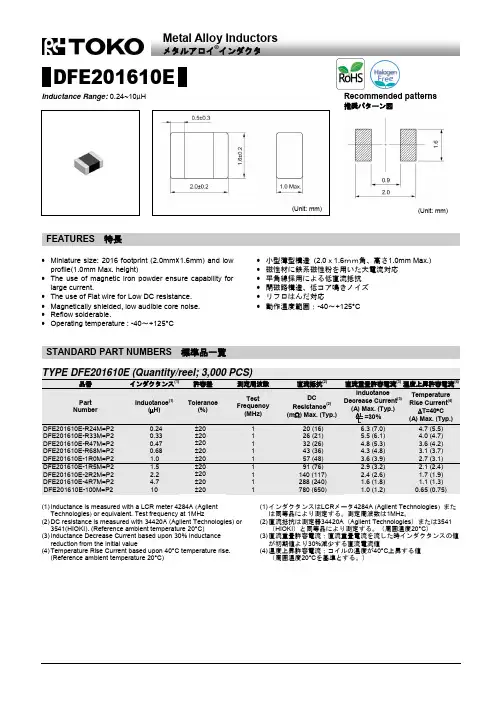
DFE201610EInductance Range: 0.24~10μH(Unit: mm)(Unit: mm)∙ Miniature size: 2016 footprint (2.0mm×1.6mm) and low profile(1.0mm Max. height)∙ The use of magnetic iron powder ensure capability for large current.∙ The use of Flat wire for Low DC resistance. ∙ Magnetically shielded, low audible core noise. ∙ Reflow solderable.∙ Operating temperature : -40~+125°C ∙ 小型薄型構造 (2.0x1.6mm角、高さ1.0mm Max.) ∙ 磁性材に鉄系磁性粉を用いた大電流対応 ∙ 平角線採用による低直流抵抗 ∙ 閉磁路構造、低コア鳴きノイズ ∙ リフロはんだ対応∙動作温度範囲:-40~+125°C(1) Inductance is measured with a LCR meter 4284A (Agilent Technologies ) or equivalent. Test frequency at 1MHz(2) DC resistance is measured with 34420A (Agilent Technologies) or 3541(HIOKI). (Reference ambient temperature 20°C)(3) Inductance Decrease Current based upon 30% inductance reduction from the initial value(4) Temperature Rise Current based upon 40°C temperature rise. (Reference ambient temperature 20°C)(1) インダクタンスはLCR メータ4284A (Agilent Technologies ) または同等品により測定する。
声明:1、本规格书若有变更,恕不另行通知,请在订购时确认;2、本规格书没有足够的空间说明详细电性能参数,仅列明了标准规格,在订购产品之前谨请与客服或选型工程师确认。
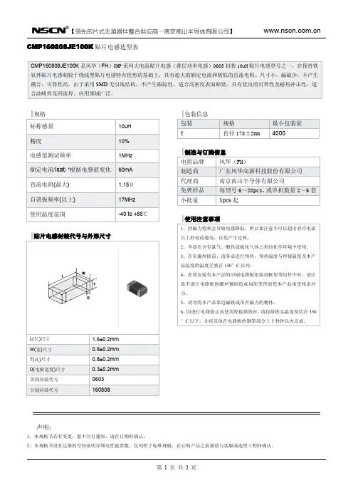
L(长)尺寸 1.6±0.2mm W(宽)尺寸0.8±0.2mm T(高)尺寸0.8±0.2mm D(电极宽度)尺寸0.3±0.2mm 英制封装代号0603公制封装代号160808声明:1、本规格书若有变更,恕不另行通知,请在订购时确认;2、本规格书没有足够的空间说明详细电性能参数,仅列明了标准规格,在订购产品之前谨请与客服或选型工程师确认。
L(长)尺寸 1.6±0.2mm W(宽)尺寸0.8±0.2mm T(高)尺寸0.8±0.2mm D(电极宽度)尺寸0.3±0.2mm 英制封装代号0603公制封装代号160808声明:1、本规格书若有变更,恕不另行通知,请在订购时确认;2、本规格书没有足够的空间说明详细电性能参数,仅列明了标准规格,在订购产品之前谨请与客服或选型工程师确认。
L(长)尺寸 1.6±0.2mm W(宽)尺寸0.8±0.2mm T(高)尺寸0.8±0.2mm D(电极宽度)尺寸0.3±0.2mm 英制封装代号0603公制封装代号160808CMP201209XD100K/M/N 贴片电感选型表声明:1、本规格书若有变更,恕不另行通知,请在订购时确认;2、本规格书没有足够的空间说明详细电性能参数,仅列明了标准规格,在订购产品之前谨请与客服或选型工程师确认。
声明:1、本规格书若有变更,恕不另行通知,请在订购时确认;2、本规格书没有足够的空间说明详细电性能参数,仅列明了标准规格,在订购产品之前谨请与客服或选型工程师确认。
L(长)尺寸 2.0±0.2mm W(宽)尺寸 1.2±0.2mm T(高)尺寸0.9±0.2mm D(电极宽度)尺寸0.5±0.3mm 英制封装代号0805公制封装代号201209声明:1、本规格书若有变更,恕不另行通知,请在订购时确认;2、本规格书没有足够的空间说明详细电性能参数,仅列明了标准规格,在订购产品之前谨请与客服或选型工程师确认。
uu16共模电感技术参数
UU16共模电感是一种电子元器件,用于电子电路中的信号滤波和电源电路中的电磁干扰滤除。
它采用磁性材料作为引线,轮廓呈U形,其中有针孔。
它的设计参数可以影响其电气性能,下面是一些常见的
UU16共模电感技术参数:
1. 额定电感值:UU16共模电感的额定电感值是指它在特定工作
频率下的电感值。
电感值通常以微亨为单位,它越大表示元件对于低
频信号的阻抗越高。
2. 额定电流:UU16共模电感的额定电流是指在正常工作条件下,可以通过电感的最大电流值。
如果电流超过额定值,可能会导致线圈
热损坏甚至烧毁元件。
3. 直流电阻:UU16共模电感的直流电阻是指电路通电后通过电
感的直流阻力。
直流电阻的大小直接影响电感器件的功率损耗和热效应。
4. 最大工作温度:UU16共模电感的最大工作温度是指元件允许
的最高工作温度。
如果温度过高,可能会导致元件雏型不良或性能退化。
5. 工作频率范围:UU16共模电感的工作频率范围是指元件保持
额定性能工作的最小和最大频率限制。
如果频率超出范围,元件将无
法正常工作。
6. 电感器件封装:UU16共模电感的封装种类通常有裸露式、贴
片式、扁平线圈式等,选择适合的封装有利于电路的布局和安装。
UU16共模电感作为电子电路中常用的基础元件之一,它的各项技术参数对于电路设计和调试至关重要。
在选择UU16共模电感时一定要
结合实际需求、设计电路和电路环境等诸多因素进行综合考虑。
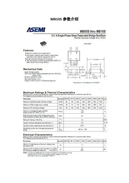
MB10S参数介绍
深圳市强元芯电子有限公司,专注电源领域12年!
供应MB10S贴片整流桥详细参数规格
内部芯片类型:台湾波峰GPP芯片
品牌:ASEMI
最大正向整流电流Io:0.5A
最大反向耐压PRV:1000V
正向压降VFM:1.0V
正向峰值电流:30A
工作温度范围:-40°C to+175°C
最大反向电流:5.0A
封装形式:MBS-4/SOP-4
应用市场:手机充电器、LED灯具等
MBS贴片整流桥相关型号:MB2S、MB4S、MB6S、MB8S、MB10S
强元芯电子是一家技术力量雄厚的公司,12年专注于电源领域的研发经验,可为客户提供全套的技术支持!本公司专业生产整流桥,肖特基,快恢复二极管,为ASEMI大陆地区一级代理商!强元芯在半导体行业有着12年的资质,以诚信经营为宗旨,打造百年诚信企业为方向,本着“客户就是上帝,要满足并超越客户需求”的客户观,快速发展;致力成为中国电子供应链中广大厂商优先选择的战略合作伙伴。
也许我们只是一个小小配件,却是您产品中不可或缺的一份子!
也许我们给你的价格不是最低的,但品质一定是最高的;我们宁可为价格解释一阵子,也不愿为质量道歉一辈子!。
共模电感uh
共模电感(Common mode Choke),又称共模扼流圈,是一种用于过滤电磁干扰(EMI)的电子元器件。
它主要应用于电脑的开关电源、板卡设计等领域,用于抑制高速信号线产生的电磁波向外辐射发射。
共模电感在变频空调、平板电视、电动汽车、逆变焊机、高频电感加热、光伏、风电等领域也有广泛应用。
共模电感的性能特点如下:
1. 在大的频率范围内有良好的衰减性能;
2. 漏感低,更好的性能稳定性;
3. 电感量偏差小;
4. 体积小,较少匝数可获得较大阻抗、电感;
5. 良好的温度稳定性,可以应用在宽的温度范围。
共模电感的制作方法一般是通过在磁芯表面绕线而成。
绕线方式、铜线线径及匝数的不同会导致共模电感的感值及阻抗发生变化。
共模电感在抑制电磁干扰方面具有很高的初始导磁率和饱和磁感应强度,同时具有卓越的温度稳定性。
这些特性使得共模电感在各种电子设备中发挥着重要的滤波作用。
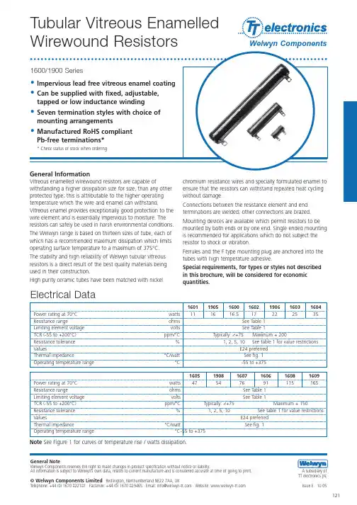
Tubular Vitreous EnamelledGeneral NoteWelwyn Components reserves the right to make changes in product specification without notice or liability.All information is subject to Welwyn’s own data, relates to current manufacture and is considered accurate at time of going to print. A subsidiary ofTT electronics plcTerminationsStyles B, 4B, AP and AW are available in all 13 tube sizes. Styles C, CB and CP are available in sizes 1601 to 1609 inclusive, 1906 and 1908Lugs (Figure 2): Pb free solder coated nickel iron. Denoted by prefix B to size reference, thus B1602Pigtails (Figure 3): 14/.193 mm copper, 150 mm minimum length. Denoted by prefix AP, thus AP1602Rigid wires (Figure 4): 1.2 mm diameter tinned copper, 32 mm minimum length.Denoted by prefix AW, thus: AW1602Lugs with screws, nuts and washers (Figure 5): Nickel plated brass screws and nuts. Denoted by prefix 4B, thus: 4B1602.Ferrule, electrically isolated (Figure 6) Connection to resistor via Pb free solder coated nickle iron lugs. Denoted by prefix CB, thus: CB1602.Ferrule, electrically live (Figure 7) Nickel plated brass. Denoted by prefix C, thus: C1602.Ferrule, electrically isolated (Figure 8): Connection to resistor via pigtails of 14/.193 mm copper, 150mm minimum length. Denoted by prefix CP thus: CP1602 Marking The resistors are legend marked with type reference, resistance value, tolerance and manufacturing date code. Value marking conforms to IEC 62.Solvent resistance: The vitreous coating and marking are resistant to all accepted industrial cleaning fluids.Resistance range (ohms)Min. for Min. for Max. for styles VC,all other all styles VCP styles43 1.6k43 2.5k66 3.0k88 5.3k66 4.5k11107.5k 1198.1k 141313.2k 171615.4k 252425.5k*Maximum total dissipation assumes that this will beevenly spread over the total element length.The recommended dissipations for each of the resistor hot spot temperatures applies to resistors mounted horizontally. If the bore is completely blocked a 15% derating is recommended. However, wherever possible, resistors should be mounted vertically with unobstructed bore.This makes best use of the chimney effect of the heated tube and will encourage a cooling stream of air through the bore. Allowances must be made, when tubular resistors are mounted in banks, for the effects produced by radiation between tubes. Appreciable reduction of hot spot temperature can be achieved by arranging that resistors are subjected to some measure of forced draught. In general, it is most efficient to extract air from the resistor enclosure and arrange that an air inlet is adjacent to the bottom of the tubes.If soft soldered connections are used the resistors should be derated where applicable to limit the hot spot temperature to 300°C.。
深圳市知用电子有限公司脉冲式大电流电感测量仪IPT1000IPT1500深圳市知用电子有限公司安全要求本仪器在测试状态会在输出端、测试线缆、夹具和被测元件上存在最高达400V的直流脉冲电压。
所以请用户阅读下面的安全须知并遵守相关的安全防范措施。
⏹测试线缆必须使用原厂提供的带有安全插头的线缆,测试夹具必须使用原厂提供的带有绝缘护套的夹具。
⏹进行测试的工作台必须具有绝缘的台面,以防高压漏电。
⏹测试过程中,该仪器的软件界面会显示一个如下图所示的高压危险的提示画面。
此时操作人员不可触碰任何线缆和夹具。
只有当软件不显示该画面时,操作人员才能连接或拆卸线缆和夹具。
⏹发现任何异常现象请勿自行拆机维修,请及时联系本公司处理。
⏹该仪器必须由经过培训的技术人员操作,并指定专人管理。
一、前言目前对于电感的测试,通常是采用LCR电桥进行的。
数字化的电桥是在被测的电感上加一个高频电压信号,通过电桥的自动平衡原理,测量电感的各种参数,如电感量,品质因数等。
由于测量的电压是一个不超过10V的交流小电压,流过电感的电流也是一个几十毫安级的小电流,电桥测到的是小信号下的电感参数。
这个方法一般是用在小信号的模拟电路上的电感元件的测量。
众所周知电感是一个非线性化的元件,电感参数和流过的电流引起的电感的磁性材料的磁化状态有很大的关系。
目前采用的是LCR电桥+偏流源测试方法的本质是在一个恒定的直流电流上叠加一个高频小信号去测量。
这种传统电桥+偏流源的测试系统,不但价格昂贵,体积庞大,操作复杂,而且最大测试电流只能在200A以内,已经远远跟不上电力电子新产品的发展。
随着大功率电力电子和新能源产品的高速发展,功率电感的电流定额也日益增长,目前已经有超过1500A电流的功率电感的需求。
工程师最关心的是功率电感在大电流下的电感量衰减是否满足设计要求,是否饱和以及饱和的程度如何。
这个问题对设计一个高可靠性低成本的电力电子和新能源产品至关重要。
二、IPT1000/1500的特点◆测量增量电感和正割电感。
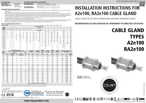
CABLE GLAND FOR USE WITH UNARMOURED AND BRAID ARMOURED CABLESINCORPORATING EU DECLARATION OF CONFORMITY TO DIRECTIVE 2014/34/EUTECHNICAL DATACABLE GLANDTYPES A2e100RA2e100INSTALLATION INSTRUCTIONS FOR A2e100, RA2e100 CABLE GLANDGlasshouse Street • St. Peters • Newcastle upon Tyne • NE6 1BSTel: +44 191 265 7411 • Fax: +44 1670 715 646E-Mail:********************************.uk•Web:Notified Body: Sira Certification Service, Unit 6, Hawarden Industrial Park, Hawarden, CH5 3US, UK0518CABLE GLAND TYPE : A2e100, RA2e100INGRESS PROTECTION: IP66, IP67, IP68PROCESS CONTROL SYSTEM : BS EN ISO 9001ISO/IEC 80079-34:2011C M PD o c u m e n t N o . F I 493 I s s u e 4Logo’s shown for illustration purposes only. Please check certification for detailsEN 60079-0:2012/A11:2013, EN 60079-7:2015, EN 60079-15:2010, EN 60079-31:2014, BS 6121:1989, EN 62444:2013David Willcock - Certification Engineer (Authorised Person)CMP Products Limited, Cramlington, UK, NE23 1WHSCAN FOR INSTALLATION VIDEOSEXPLOSIVE ATMOSPHERES CLASSIFICATIONATEX CERTIFICATION No : SIRA16ATEX3165, SIRA16ATEX4020ATEX CERTIFICATION CODE : ^ II 2G Ex eb IIC Gb, II 1D Ex ta IIIC Da IP66, IP67, IP68^ II 3G Ex nRc IIC Gc IP66 ^ I M2 Ex eb I Mb IP66, IP67, IP68IECEx CERTIFICATION No : IECEx SIR 16.0053IECEx CERTIFICATION CODE : Ex eb IIC Gb, Ex ta IIIC Da, Ex nRc IIC Gc, Ex eb I Mb IP66, IP67, IP68A2e100 - no face seal RA2e100 - with face seal1. Read all instructions before beginning installation. Installation shall only be performed by competent, suitably trained personnel (in accordance with EN/IEC 60079-14) using the correct tools; spanners should be used for tightening.2.Inspection and maintenance shall only be performed by competent, suitably trained personnel (in accordance with EN/IEC 60079-14 (Initial Inspection) and EN/IEC 60079-17).3.Ingress Protection Statement; The interface between a cable entry device and its associated enclosure / cable entry cannot be defined. It is the user’s responsibility to ensure that a minimum protection level (IP54 for explosive gas atmospheres and IP6X for explosive dust atmospheres) is maintained at the interface. Entry component threads may need additional sealing to maintain the ingress protection rating and/orrestricted breathing performance as applicable to the equipment to which it will be attached, such as by either a sealing washer, thread sealant or integrated ‘O’ ring face seal (RA2e100). Reference should also be made to the information from EN 60079-14:2014, Clause 10, Table 10, (Note: When fitted to a threaded entry, all tapered threads will automatically provide an ingress protection rating of IP6X).4. The standard product temperature range is -60°C to +130°C. The equipment should not be used outside of this range.5. Cable glands do not have any serviceable parts and are therefore not intended to be repaired.6. Cable glands are manufactured from Brass, Nickel Plated Brass, Stainless Steel, Mild Steel or Aluminium, with Silicone seals. The end user shall consider the performance of these materials with regard to attack by aggressive substances that may be present in the hazardous area. Consideration should be given to potential degradation due to galvanic corrosion at the interface of dis-similar metallic materials.7.It is the end user’s responsibility to ensure the equipment materials are suitable for their final installation location. If in doubt consult CMP Products Limited.IMPORTANT NOTES FOR INSTALLERSSPECIAL CONDITIONS FOR SAFE USE None INSTALLATION INSTRUCTIONS FOR CMP CABLE GLAND A2e100, RA2e100CABLE GLAND COMPONENTS - It is not necessary to dismantle the cable gland any further than illustrated below 1. Entry Item 2. Seal 3. Seal NutPLEASE READ ALL INSTRUCTIONS CAREFULLY BEFORE BEGINNING THE INSTALLATION1. It is not necessary to dismantle the gland any further than illustrated below.where required to reveal the insulated conductors.4. Slacken the seal nut (3) to relax the seal (2).5. Only using finger pressure, tighten the seal nut until light resistance to tightening is met.Then either use the seal tightening guide tape or table on the rear of the page to determine how much further to tighten the seal using a spanner (using the outer seal tightening guide is recommended).Wrap the seal tightening guide tape around the cable to show the amount of spanner turns needed (as shown here). Make sure the correct side of the seal tightening guide tape is used depending on the cable gland size.。
2017/1/5笔记本电脑1040一体成型电感常用型号【捷比信科技】走进捷比信大毅(TA-I)光颉(Viking)阿尔卑斯(ALPS)公司简介资讯信息联系我们首页 > 行业资讯 > 笔记本电脑1040一体成型电感常用型号笔记本电脑1040一体成型电感常用型号笔记本电脑1040一体成型电感常用型号捷比信一体成型电感特点:过大电流,屏蔽性能好,贴片封装, 捷比信一体成型电感应用: 适用于电源供应器、个人电脑和其它掌上型电子设备中电源线路上直流对直流整流的应用。
适用于高可靠要求的车用,军用,医用,航空航天等行业。
以下是捷比信1040模压一体成型电感常用型号:PSP(A/F)J1040R22M PSP(A/F)J1040R36M PSP(A/F)J1040R47M PSP(A/F)J1040R68M PSP(A/F)J10401R0M PSP(A/F)J10401R5MPSP(A/F)J10402R2M PSP(A/F)J10403R3M PSP(A/F)J10404R7M PSP(A/F)J10406R8M PSP(A/F)J1040100M PSP(A/F)J1040220MPSP(A/F)J1040330M 查货,索样请来电洽询深圳市捷比信科技有限公司C: BY:陆 TIME:20170104随机推荐:光颉功率电感特点充电桩市场上演圈地竞赛台湾大毅厂家电阻 大功率采样电阻“互联网+”时期:工业电气行业如何转型?电子元器件与电商的大时代电动平衡车:让生活尽享闲适 慢活人生解析集成电路杀手:可怕的静电大毅5930贴片分流电阻,功率高达6W一旦安全问题解决 亚马逊送货无人机能否就实现无人机市场将被引爆?2016年将“逆风飞翔”知识版权所有 © 深圳市捷比信科技有限公司服务热线:+8675529796190 传真:+8675529796149 地址:深圳市龙华新区东环一路皇嘉中心A座820822 Email:sales@ 电阻产品: 低温漂电阻 大毅电阻 Viking光颉电阻 高精密低温漂电阻 采样电阻 大功率无感电阻 插件精密电阻 高频电感 汽车专用电阻 贴片保险丝 低温漂精密电阻 毫欧电阻 排阻泰艺晶振产品: 有源晶振 晶振封装 晶振频率 晶振精度 32.768K晶振 恒温晶振 高温晶振 可编程晶振 温补晶振 压控晶振 无源晶振 贴片晶振 插件晶振 钟振 石英振荡器 晶振波形输出 SCcut切晶振ALPS代理产品: ALPS编码器 ALPS电位器 ALPS开关按键 ALPS卡座连接器 ALPS TACT Switch网站统计/info/20141506.html1/1。
Wire Wound SMD Power Inductors – SWPA SeriesOperating temperature range: -40℃~+125℃ (Including self-heating)FEATURES● Magnetic-resin shielded construction reduces buzz noise to ultra-low levels● Metallization on ferrite core results in excellent shock resistance and damage-free durability ● Closed magnetic circuit design reduces leakage flux and Electro Magnetic Interference (EMI) ● 30% higher current rating than conventional inductors of equal size ● Takes up less PCB real estate and save more powerAPPLICATIONS● Smart phone, smart TV, set top box, notebook ● Car navigation systems, telecomm base stations ● VR, AR ● LED lightingPRODUCT IDENTIFICATIONSWPA3012 S 1R0 N T□□□① ② ③ ④ ⑤ ⑥ ⑦②External Dimensions (L×W×H) [mm] 252010 2.5×2.0×1.0 252012 2.5×2.0×1.2 3010 3.0×3.0×1.03012 3.0×3.0×1.2 3015 3.0×3.0×1.5 4010 4.0×4.0×1.0 4012 4.0×4.0×1.2 4018 4.0×4.0×1.8 4020 4.0×4.0×2.0 4026 4.0×4.0×2.6 4030 4.0×4.0×3.0 5012 5.0×5.0×1.2 5020 5.0×5.0×2.0 5040 5.0×5.0×4.0 6020 6.0×6.0×2.0 6028 6.0×6.0×2.8 6040 6.0×6.0×4.0 6045 6.0×6.0×4.5 8040 8.0×8.0×4.0 8050 8.0×8.0×5.0 8060 8.0×8.0×6.08065 8.0×8.0×6.5 ① Type SWPAWire Wound SMD Power Inductor③ Feature TypeS Standard ④ Nominal InductanceExample Nominal Value1R0 1.0μH 100 10μH⑤ Inductance ToleranceK ±10%M ±20% N ±30% ⑥ PackingTTape Carrier Package⑦ Design Code □□□Standard product is blankFig.1 Fig.2Unit: mmSeriesShapeABCD E Fa Typ.b Typ.c Typ.SWPA252010S Fig.1 2.5±0.1 2.0±0.1 1.0 Max. 2.0±0.20.80±0.20.80±0.2 0.80 0.85 2.0 SWPA252012S Fig.1 2.5±0.1 2.0±0.1 1.2 Max. 2.0±0.20.80±0.20.80±0.2 0.80 0.85 2.0 SWPA3010S Fig.2 3.0±0.2 3.0±0.2 1.0 Max. 2.5±0.20.75±0.2 1.5±0.2 1.5 0.8 2.7 SWPA3012S Fig.2 3.0±0.2 3.0±0.2 1.2 Max. 2.5±0.20.75±0.2 1.5±0.2 1.5 0.8 2.7 SWPA3015S Fig.2 3.0±0.2 3.0±0.2 1.5 Max. 2.5±0.20.75±0.2 1.5±0.2 1.5 0.8 2.7 SWPA4010S Fig.2 4.0±0.2 4.0±0.2 1.0 Max. 3.3±0.20.95±0.2 2.1±0.2 1.9 1.1 3.7 SWPA4012S Fig.2 4.0±0.2 4.0±0.2 1.2 Max. 3.3±0.20.95±0.2 2.1±0.2 1.9 1.1 3.7 SWPA4018S Fig.2 4.0±0.2 4.0±0.2 1.8 Max. 3.3±0.20.95±0.2 2.1±0.2 1.9 1.1 3.7 SWPA4020S Fig.2 4.0±0.2 4.0±0.2 2.0 Max. 3.3±0.20.95±0.2 2.1±0.2 1.9 1.1 3.7 SWPA4026S Fig.2 4.0±0.2 4.0±0.2 2.6 Max. 3.3±0.20.95±0.2 2.1±0.2 1.9 1.1 3.7 SWPA4030S Fig.2 4.0±0.2 4.0±0.2 3.0 Max. 3.3±0.20.95±0.2 2.1±0.2 1.9 1.1 3.7 SWPA5012S Fig.3 5.0±0.2 5.0±0.2 1.2 Max. 4.0±0.2 1.25±0.2 2.5±0.2 2.3 1.4 4.2 SWPA5020S Fig.3 5.0±0.2 5.0±0.2 2.0 Max. 4.0±0.2 1.25±0.2 2.5±0.2 2.3 1.4 4.2 SWPA5040S Fig.3 5.0±0.2 5.0±0.2 4.0 Max. 4.0±0.2 1.25±0.2 2.5±0.2 2.3 1.4 4.2 SWPA5045S Fig.3 5.0±0.2 5.0±0.2 4.5 Max. 4.0±0.2 1.30±0.2 2.5±0.2 2.3 1.4 4.2 SWPA6020S Fig.2 6.0±0.3 6.0±0.3 2.0 Max. 4.9±0.3 1.55±0.3 2.9±0.3 2.8 1.7 5.7 SWPA6028S Fig.2 6.0±0.3 6.0±0.3 2.8 Max. 4.9±0.3 1.55±0.3 2.9±0.3 2.8 1.7 5.7 SWPA6040S Fig.2 6.0±0.3 6.0±0.3 4.0 Max. 4.9±0.3 1.55±0.3 2.9±0.3 2.8 1.7 5.7 SWPA6045S Fig.2 6.0±0.3 6.0±0.3 4.5 Max.4.9±0.3 1.55±0.3 2.9±0.3 2.8 1.75.7 SWPA8040S Fig.2 8.0±0.3 8.0±0.3 4.2 Max.6.3±0.3 2.00±0.3 4.0±0.3 3.8 2.27.5SWPA8050S Fig.3 8.0±0.3 8.0±0.3 5.0 Max. 6.3±0.3 2.00±0.3 4.0±0.3 3.8 2.2 7.5 SWPA8060S Fig.3 8.0±0.3 8.0±0.3 6.0 Max 6.3±0.3 2.00±0.3 4.0±0.3 3.8 2.2 7.5 SWPA8065S Fig.3 8.0±0.3 8.0±0.3 6.5 Max.6.3±0.32.00±0.34.0±0.3 3.8 2.2 7.5SHAPE AND DIMENSIONS SWPA252010S SeriesPart NumberInductance DC ResistanceSelf-resonantFrequencySaturation Current*3Heat Rating Current*4@100kHz,1V Max. Typ.Min. Max. Typ. Max. Typ.Units μH ΩMHz A A Symbol L DCRS.R.F Isat Irms SWPA252010SR47NT 0.47±30% 0.056 0.047206 2.50 3.35 2.35 2.56 SWPA252010SR56NT 0.56±30% 0.072 0.060160 2.90 3.20 2.00 2.18 SWPA252010SR68NT 0.68±30% 0.074 0.062129 2.20 2.75 2.00 2.18 SWPA252010S1R0NT 1.0±30% 0.1080.090100 1.85 2.20 1.65 1.80 SWPA252010S1R5NT 1.5±30% 0.182 0.15281 1.80 2.10 1.30 1.42 SWPA252010S2R2NT 2.2±30% 0.209 0.17461 1.20 1.60 1.20 1.31 SWPA252010S3R3MT 3.3±20% 0.328 0.27347 1.05 1.30 0.90 0.98 SWPA252010S4R7MT 4.7±20% 0.563 0.46942 0.95 1.15 0.70 0.76 SWPA252010S5R6MT 5.6±20% 0.563 0.46935 0.80 0.95 0.73 0.80 SWPA252010S6R8MT 6.8±20% 0.896 0.74731 0.78 0.92 0.59 0.64 SWPA252010S100MT 10±20% 1.092 0.91027 0.65 0.78 0.50 0.55SWPA252012S SeriesPart NumberInductance DC Resistance Self-resonant FrequencySaturation Current*3Heat Rating Current*4@100kHz,1V Max.Typ.Min. Max.Typ. Max. Typ.Units μH Ω MHz A A Symbol L DCR S.R.F Isat IrmsSWPA252012SR47NT 0.47±30% 0.0610.047160 3.82 4.27 2.15 2.34 SWPA252012SR68NT 0.68±30% 0.0740.057140 3.28 3.68 1.95 2.13 SWPA252012S1R0NT 1.0±30% 0.0900.069110 2.59 2.90 1.93 2.10 SWPA252012S1R2NT 1.2±30% 0.1290.099100 2.38 2.67 1.46 1.59 SWPA252012S1R5MT 1.5±20% 0.1470.11397 2.24 2.51 1.40 1.53 SWPA252012S1R5NTY01 1.5±30% 0.1300.10 63 1.80 2.00 1.45 1.58 SWPA252012S2R2MT 2.2±20% 0.2160.16669 1.85 2.07 1.15 1.25 SWPA252012S2R2NTY02 2.2±30% 0.1530.11853 1.55 1.75 1.30 1.42 SWPA252012S2R7MT 2.7±20% 0.2390.18463 1.72 1.92 1.09 1.19 SWPA252012S3R3MT 3.3±20% 0.2640.20362 1.61 1.80 1.04 1.13 SWPA252012S3R6MT 3.6±20% 0.3480.26853 1.46 1.64 0.90 0.98 SWPA252012S4R3MT 4.3±20% 0.3770.29051 1.37 1.53 0.87 0.95 SWPA252012S4R7MT 4.7±20% 0.3770.29047 1.12 1.25 0.84 0.92 SWPA252012S5R1MT 5.1±20% 0.5000.38544 1.23 1.37 0.75 0.82SWPA252012S5R6MT 5.6±20%0.5380.41438 1.11 1.25 0.73 0.80SWPA252012S6R2MT 6.2±20% 0.5420.41738 1.03 1.16 0.73 0.80 SWPA252012S6R8MT 6.8±20% 0.5810.44738 0.98 1.09 0.69 0.75 SWPA252012S7R5MT 7.5±20% 0.6110.47035 0.97 1.09 0.68 0.74SWPA252012S8R2MT 8.2±20% 0.6580.50636 0.98 1.10 0.65 0.71 SWPA252012S9R1MT 9.1±20%0.6900.53134 0.91 1.02 0.62 0.68SWPA252012S100MT 10±20% 0.6900.53134 0.79 0.88 0.62 0.68SWPA252012S120MT 12±20%1.0750.82728 0.78 0.88 0.51 0.56 SWPA252012S150MT 15±20%1.591 1.22425 0.68 0.77 0.42 0.46SWPA3010S Series Part NumberInductanceDC ResistanceSelf-resonant FrequencySaturation Current*3Heat Rating Current*4@100kHz,1V Max.Typ.Min. Max.Typ. Max. Typ.Units μH ΩMHz A A Symbol L DCR S.R.F Isat IrmsSWPA3010S1R0NT 1.0±30% 0.0850.065180 1.40 2.10 1.45 1.80 SWPA3010S1R2NT 1.2±30% 0.0850.065137 1.25 1.70 1.45 1.80 SWPA3010S1R5NT 1.5±30% 0.1040.080120 1.27 1.70 1.30 1.60 SWPA3010S2R2NT 2.2±30% 0.1430.110100 1.15 1.50 1.09 1.40 SWPA3010S2R7NT 2.7±30% 0.1690.13090 1.00 1.20 1.02 1.40 SWPA3010S3R3NT 3.3±30% 0.1890.14574 0.97 1.20 0.96 1.20 SWPA3010S3R6MT 3.6±20% 0.2150.16567 0.95 1.20 0.90 1.10 SWPA3010S4R7MT 4.7±20% 0.2930.22559 0.75 1.05 0.77 1.10 SWPA3010S5R6MT 5.6±20% 0.322 0.248 40 0.58 0.65 0.70 1.05 SWPA3010S6R8MT 6.8±20% 0.3970.30542 0.55 0.72 0.66 0.96 SWPA3010S8R2MT 8.2±20% 0.520 0.40 23 0.55 0.70 0.58 0.70 SWPA3010S100MT 10±20% 0.5200.40 39 0.55 0.75 0.58 0.70 SWPA3010S120MT 12±20% 0.6570.50536 0.43 0.65 0.52 0.67 SWPA3010S150MT 15±20% 0.7930.61030 0.42 0.57 0.47 0.57 SWPA3010S220MT 22±20% 1.2090.93028 0.35 0.48 0.38 0.52 SWPA3010S270MT 27±20% 1.404 1.08025 0.30 0.45 0.35 0.50 SWPA3010S330MT 33±20% 2.015 1.55018 0.29 0.42 0.30 0.55 SWPA3010S390MT 39±20% 2.275 1.75018 0.28 0.38 0.28 0.53 SWPA3010S430MT 43±20% 2.340 1.80 18 0.23 0.36 0.27 0.52 SWPA3010S470MT 47±20% 2.535 1.95018 0.22 0.35 0.26 0.52 SWPA3010S510MT 51±20% 2.860 2.20 18 0.21 0.33 0.25 0.48SWPA3010S560MT 56±20% 3.016 2.32016 0.21 0.280.24 0.35SWPA3012S SeriesPart NumberInductanceDC ResistanceSelf-resonant FrequencySaturation Current*3Heat Rating Current*4@100kHz,1V Max.Typ. Min. Max.Typ. Max. Typ.Units μH ΩMHz A A Symbol L DCR S.R.F Isat Irms SWPA3012SR22NT 0.22±30% 0.022 0.017 321 5.30 6.00 3.00 3.30 SWPA3012SR82NT 0.82±30% 0.039 0.030 180 2.05 2.80 2.47 3.00 SWPA3012S1R0NT 1.0±30% 0.052 0.040 120 1.87 2.80 2.20 2.70 SWPA3012S1R2NT 1.2±30% 0.059 0.045 120 2.22 2.50 2.01 2.20 SWPA3012S1R5NT 1.5±30% 0.0590.045 110 1.62 1.90 2.01 2.20 SWPA3012S1R8NT 1.8±30% 0.0820.063 90 1.30 1.90 1.65 1.80 SWPA3012S2R2NT 2.2±30% 0.0980.075 84 1.20 1.90 1.55 1.70 SWPA3012S2R4NT 2.4±30% 0.0880.068 100 1.15 1.50 1.60 1.70 SWPA3012S2R7NT 2.7±30% 0.1100.085 65 1.14 1.50 1.48 1.50 SWPA3012S3R3MT 3.3±20% 0.1300.10 64 1.05 1.50 1.36 1.40 SWPA3012S3R6MT 3.6±20% 0.1300.10 36 1.05 1.50 1.36 1.40 SWPA3012S3R9MT 3.9±20% 0.189 0.145 61 1.00 1.30 1.24 1.30 SWPA3012S4R7MT 4.7±20% 0.1560.120 61 0.90 1.00 1.24 1.30 SWPA3012S5R6MT 5.6±20% 0.2260.17461 0.80 1.10 1.13 1.24 SWPA3012S6R8MT 6.8±20% 0.2470.190 61 0.75 0.90 0.98 1.10 SWPA3012S100MT 10±20% 0.3450.265 42 0.60 0.88 0.83 0.90 SWPA3012S120MT 12±20% 0.4490.345 32 0.48 0.67 0.73 0.84SWPA3012S SeriesPart NumberInductanceDC ResistanceSelf-resonant FrequencySaturation Current*3Heat Rating Current*4@100kHz,1V Max.Typ. Min. Max.Typ. Max. Typ.Units μH Ω MHz A A Symbol L DCR S.R.F Isat Irms SWPA3012S220MT 22±20% 0.839 0.645 23 0.42 0.52 0.53 0.59 SWPA3012S270MT 27±20% 1.131 0.870 21 0.35 0.48 0.47 0.51 SWPA3012S330MT 33±20% 1.138 0.875 18 0.36 0.46 0.46 0.50 SWPA3012S360MT 36±20% 1.235 0.950 18 0.34 0.44 0.44 0.48 SWPA3012S390MT 39±20% 1.729 1.330 18 0.30 0.39 0.37 0.41 SWPA3012S470MT 47±20% 1.885 1.450 14 0.27 0.35 0.35 0.40 SWPA3012S560MT 56±20% 1.794 1.380 9 0.26 0.33 0.28 0.40 SWPA3012S680MT 68±20% 2.171 1.670 7 0.24 0.29 0.33 0.37 SWPA3012S820MT 82±20% 3.302 2.540 7 0.17 0.27 0.27 0.31 SWPA3012S101MT 100±20% 3.718 2.860 5 0.21 0.23 0.25 0.29SWPA3015S SeriesPart NumberInductanceDC ResistanceSelf-resonant Frequency Saturation Current*3Heat Rating Current*4@100kHz,1V Max.Typ.Min.Max.Typ. Max. Typ.Units μH ΩMHz A ASymbol L DCR S.R.F Isat Irms SWPA3015SR50NT 0.5±30% 0.039 0.030 162 3.90 4.20 2.60 2.80 SWPA3015S1R0NT 1.0±30% 0.039 0.030 150 2.32 2.80 2.35 2.50 SWPA3015S1R2NT 1.2±30% 0.052 0.040 110 2.21 3.10 1.95 2.30 SWPA3015S1R5NT 1.5±30% 0.065 0.050 100 2.30 2.70 1.70 2.20 SWPA3015S1R8NT 1.8±30% 0.065 0.050 92 1.75 2.20 1.70 2.20 SWPA3015S2R2NT 2.2±30% 0.078 0.060 86 1.60 2.00 1.60 2.00 SWPA3015S2R7NT 2.7±30% 0.098 0.075 64 1.52 1.90 1.43 1.90 SWPA3015S3R3MT 3.3±20% 0.104 0.080 68 1.32 1.81 1.36 1.60 SWPA3015S3R6MT 3.6±20% 0.137 0.105 59 1.28 1.60 1.20 1.50 SWPA3015S3R9MT 3.9±20% 0.137 0.105 47 1.20 1.40 1.20 1.50 SWPA3015S4R3MT 4.3±20% 0.150 0.115 53 1.20 1.40 1.14 1.30 SWPA3015S4R7MT 4.7±20% 0.163 0.125 46 1.10 1.40 1.09 1.30 SWPA3015S5R1MT 5.1±20% 0.173 0.133 49 1.00 1.20 1.05 1.20 SWPA3015S6R2MT 6.2±20% 0.254 0.195 46 1.00 1.20 0.86 1.00 SWPA3015S6R8MT 6.8±20% 0.260 0.20 39 0.85 1.10 0.85 1.10 SWPA3015S100MT 10±20% 0.325 0.250 41 0.72 0.92 0.77 0.90 SWPA3015S120MT 12±20% 0.416 0.320 32 0.70 0.90 0.68 0.89 SWPA3015S150MT 15±20% 0.455 0.350 30 0.66 0.88 0.65 0.72 SWPA3015S180MT 18±20% 0.559 0.430 23 0.56 0.72 0.59 0.72 SWPA3015S220MT 22±20% 0.598 0.46023 0.52 0.68 0.57 0.69 SWPA3015S270MT 27±20% 0.949 0.730 22 0.48 0.56 0.45 0.56 SWPA3015S330MT 33±20% 1.066 0.820 20 0.44 0.53 0.43 0.51 SWPA3015S390MT 39±20% 1.294 0.995 14 0.41 0.55 0.39 0.44 SWPA3015S430MT 43±20% 1.378 1.060 16 0.37 0.43 0.37 0.48 SWPA3015S470MT 47±20% 1.625 1.250 14 0.35 0.43 0.35 0.44 SWPA3015S560MT 56±20% 1.664 1.280 13 0.33 0.42 0.34 0.41 SWPA3015S620MT 62±20% 2.093 1.610 13 0.30 0.40 0.30 0.41 SWPA3015S680MT 68±20% 3.510 2.700 110.28 0.37 0.23 0.31 SWPA3015S101MT 100±20% 4.043 3.110 6.3 0.23 0.25 0.21 0.25SWPA4010S SeriesPart NumberInductanceDC ResistanceSelf-resonant FrequencySaturation Current*3Heat Rating Current*4@100kHz,1V Max.Typ.Min.Max.Typ. Max. Typ.Units μH ΩMHz AASymbol L DCR S.R.F Isat Irms SWPA4010S1R0NT 1.0±30% 0.067 0.056 116 2.00 2.30 1.90 2.40 SWPA4010S1R5NT 1.5±30% 0.084 0.070 94 1.68 2.00 1.70 2.00 SWPA4010S2R2MT 2.2±20% 0.102 0.085 73 1.20 1.50 1.50 2.00 SWPA4010S3R3MT 3.3±20% 0.120 0.10 58 1.10 1.40 1.40 1.80 SWPA4010S4R7MT 4.7±20% 0.168 0.140 47 0.95 1.10 1.20 1.50 SWPA4010S6R8MT 6.8±20% 0.240 0.20 38 0.80 0.95 1.00 1.20 SWPA4010S100MT 10±20% 0.360 0.30 31 0.62 0.75 0.75 1.00 SWPA4010S150MT 15±20% 0.516 0.43024 0.54 0.610.60 0.85 SWPA4010S220MT 22±20% 0.684 0.570 19 0.45 0.520.50 0.75SWPA4012S SeriesPart NumberInductance DC ResistanceSelf-resonant FrequencySaturation Current*3Heat Rating Current*4@100kHz,1V Max.Typ.Min.Max.Typ. Max. Typ.Units μH ΩMHz A ASymbol L DCR S.R.F Isat Irms SWPA4012SR82NT 0.82±30% 0.065 0.050 150 3.02 3.30 1.65 2.50 SWPA4012S1R0NT 1.0±30% 0.065 0.050 120 2.61 3.20 1.65 2.50 SWPA4012S1R5NT 1.5±30% 0.085 0.065 90 2.10 2.70 1.46 2.20 SWPA4012S1R8NT 1.8±30% 0.104 0.080 88 2.12 2.60 1.32 1.90 SWPA4012S2R2NT 2.2±30% 0.104 0.080 74 1.76 2.30 1.32 1.90 SWPA4012S2R7NT 2.7±30% 0.117 0.090 71 1.90 2.30 1.25 1.70 SWPA4012S3R3NT 3.3±30% 0.143 0.110 60 1.72 2.10 1.12 1.60 SWPA4012S3R6NT 3.6±30% 0.143 0.110 57 1.20 1.70 1.12 1.60 SWPA4012S4R3NT 4.3±30% 0.182 0.140 54 1.58 1.70 1.00 1.50 SWPA4012S4R7NT 4.7±30% 0.163 0.125 50 1.15 1.80 1.05 1.50 SWPA4012S5R1NT 5.1±30% 0.201 0.155 50 1.55 1.60 0.95 1.50 SWPA4012S5R6NT 5.6±30% 0.182 0.140 42 1.00 1.60 1.00 1.20 SWPA4012S6R8MT 6.8±20% 0.257 0.198 40 0.85 1.40 0.84 1.20 SWPA4012S100MT 10±20% 0.345 0.265 33 0.80 1.10 0.77 1.00 SWPA4012S120MT 12±20% 0.377 0.290 32 0.66 1.00 0.70 0.95 SWPA4012S150MT 15±20% 0.442 0.340 25 0.56 0.80 0.64 0.85 SWPA4012S180MT 18±20% 0.611 0.470 23 0.55 0.75 0.55 0.80 SWPA4012S220MT 22±20% 0.763 0.587 20 0.46 0.70 0.49 0.75 SWPA4012S270MT 27±20% 0.936 0.720 18 0.50 0.70 0.45 0.60 SWPA4012S330MT 33±20% 1.053 0.810 17 0.42 0.60 0.42 0.58 SWPA4012S360MT 36±20% 1.170 0.90 14 0.40 0.50 0.40 0.56 SWPA4012S390MT 39±20% 1.430 1.10 16 0.55 0.66 0.37 0.50 SWPA4012S470MT 47±20% 1.430 1.10 12 0.35 0.50 0.37 0.50 SWPA4012S560MT 56±20% 1.625 1.250 11 0.33 0.45 0.33 0.46 SWPA4012S680MT 68±20% 2.535 1.950 11 0.38 0.45 0.27 0.45 SWPA4012S820MT 82±20% 2.782 2.140 11 0.28 0.40 0.26 0.36SWPA4018S SeriesPart NumberInductance DC ResistanceSelf-resonantFrequencySaturation Current*3Heat RatingCurrent*4@100kHz,1V Max.Typ.Min. Max.Typ. Max. Typ.Units μH ΩMHz A ASymbol L DCR S.R.F Isat Irms SWPA4018SR47NT 0.47±30% 0.0180.014155 4.30 5.20 4.00 4.50 SWPA4018SR68NT 0.68±30% 0.0260.020128 4.90 5.60 3.30 3.80 SWPA4018S1R0NT 1.0±30% 0.0330.02580 4.80 5.20 2.00 3.30 SWPA4018S1R5NT 1.5±30% 0.0390.03065 3.35 4.00 1.80 3.20 SWPA4018S1R8NT 1.8±30% 0.0440.03454 3.00 3.40 2.00 2.80 SWPA4018S2R2MT 2.2±20% 0.0590.04552 2.70 3.20 1.65 2.60 SWPA4018S3R3MT 3.3±20% 0.0910.07044 2.45 2.90 1.23 2.10 SWPA4018S4R7MT 4.7±20% 0.1170.09034 1.70 2.20 1.20 1.80 SWPA4018S6R8MT 6.8±20% 0.1430.11029 1.45 2.00 1.06 1.50 SWPA4018S100MT 10±20% 0.2340.18024 1.30 1.60 0.84 1.20 SWPA4018S150MT 15±20% 0.3250.25019 0.94 1.10 0.65 1.00 SWPA4018S220MT 22±20% 0.4680.36016 0.80 0.88 0.59 0.85 SWPA4018S270MT 27±20% 0.6110.47027 0.47 0.62 0.52 0.90 SWPA4018S330MT 33±20% 0.6890.53012 0.56 0.75 0.49 0.72 SWPA4018S470MT 47±20% 0.8450.65010 0.57 0.70 0.42 0.65 SWPA4018S680MT 68±20% 1.30 1.0 8.3 0.47 0.51 0.32 0.52 SWPA4018S101MT 100±20% 2.275 1.750 6.5 0.40 0.44 0.25 0.41 SWPA4018S151MT 150±20% 3.250 2.50 5.5 0.31 0.34 0.22 0.36 SWPA4018S221MT 220±20% 5.20 4.0 4 0.27 0.30 0.17 0.27SWPA4020S SeriesPart NumberInductance DC ResistanceSelf-resonantFrequencySaturation Current*3Heat RatingCurrent*4@100kHz,1V Max.Typ. Min. Max.Typ. Max. Typ.Units μH ΩMHz A ASymbol L DCR S.R.F Isat IrmsSWPA4020SR24MT 0.24±20% 0.0140.011283 10.5 12.5 4.50 5.20 SWPA4020SR33NT 0.33±30% 0.0160.013223 7.50 8.50 3.30 4.90 SWPA4020SR47NT 0.47±30% 0.0290.022160 7.00 7.50 3.30 3.70 SWPA4020SR68NT 0.68±30% 0.0360.028120 6.40 6.60 2.80 3.30 SWPA4020S1R0NT 1.0±30% 0.0380.02975 4.78 5.20 2.15 3.20 SWPA4020S1R2NT 1.2±30% 0.0380.02972 5.10 5.60 2.15 3.20 SWPA4020S1R5NT 1.5±30% 0.0460.03571 4.45 4.90 1.98 3.00 SWPA4020S2R2NT 2.2±30% 0.0520.04049 3.40 3.70 1.85 2.80 SWPA4020S3R3MT 3.3±20% 0.0910.07044 3.20 3.50 1.40 2.50 SWPA4020S3R6MT 3.6±20% 0.0720.05549 2.80 3.00 1.54 2.50 SWPA4020S4R7MT 4.7±20% 0.0980.07542 2.35 2.50 1.34 2.00 SWPA4020S5R1MT 5.1±20% 0.111 0.08542 2.30 2.50 1.27 1.80 SWPA4020S5R6MT 5.6±20% 0.1170.09030 2.20 2.40 1.22 1.80 SWPA4020S6R2MT 6.2±20% 0.1500.11536 2.15 2.30 1.08 1.60 SWPA4020S6R8MT 6.8±20% 0.1630.12533 2.20 2.40 1.04 1.60 SWPA4020S7R5MT 7.5±20% 0.1500.11530 1.85 2.00 1.08 1.50 SWPA4020S8R2MT 8.2±20% 0.1630.12527 1.75 1.90 1.04 1.40 SWPA4020S100MT 10±20% 0.2150.16526 1.60 1.70 0.90 1.20 SWPA4020S120MT 12±20% 0.2280.17526 1.50 1.60 0.88 1.20 SWPA4020S150MT 15±20% 0.2990.23024 1.35 1.50 0.77 1.10SWPA4020S SeriesPart NumberInductance DC ResistanceSelf-resonantFrequencySaturation Current*3Heat RatingCurrent*4@100kHz,1V Max.Typ.Min. Max.Typ. Max. Typ.Units μH ΩMHz A ASymbol L DCR S.R.F Isat Irms SWPA4020S330MT 33±20% 0.7150.55011 0.850.930.490.68SWPA4020S390MT 39±20% 0.8450.65011 0.820.900.460.64SWPA4020S430MT 43±20% 0.8580.66010 0.770.850.450.63SWPA4020S470MT 47±20% 0.9230.71010 0.740.810.440.61SWPA4020S510MT 51±20% 0.9750.75010 0.700.770.420.59SWPA4020S560MT 56±20% 1.0400.80 10 0.660.720.410.57SWPA4020S620MT 62±20% 1.1700.90 9.6 0.650.710.390.52SWPA4020S680MT 68±20% 1.380 1.0607.7 0.610.670.360.50SWPA4020S750MT 75±20% 1.510 1.1607.7 0.700.770.350.49SWPA4020S820MT 82±20% 1.520 1.1707.2 0.500.550.340.47SWPA4020S101MT 100±20% 2.020 1.550 6.3 0.480.530.310.43 SWPA4026S SeriesPart NumberInductance DC ResistanceSelf-resonantFrequencySaturation Current*3Heat RatingCurrent*4@100kHz,1V Max.Typ. Min. Max.Typ. Max. Typ.Units μH ΩMHz A ASymbol L DCR S.R.F Isat Irms SWPA4026S1R0NT 1.0±30% 0.0310.024151 3.303.803.003.30SWPA4026S1R2NT 1.2±30% 0.0390.030120 3.103.402.303.30SWPA4026S1R5NT 1.5±30% 0.0390.030100 2.402.902.303.10SWPA4026S2R2MT 2.2±20% 0.0520.04096 2.102.402.003.80SWPA4026S3R3MT 3.3±20% 0.0650.05058 1.802.001.702.50SWPA4026S4R7MT 4.7±20% 0.0720.05546 1.451.701.602.30SWPA4026S6R8MT 6.8±20% 0.0850.06533 1.301.501.502.00SWPA4026S100MT 10±20% 0.1100.08526 1.001.201.301.90SWPA4026S150MT 15±20% 0.1430.11019 0.901.001.101.50SWPA4026S220MT 22±20% 0.2140.16513 0.600.800.901.40SWPA4026S330MT 33±20% 0.3510.2709 0.550.650.701.00SWPA4026S470MT 47±20% 0.3900.30 6 0.400.550.650.90 SWPA4030S SeriesPart NumberInductance DC ResistanceSelf-resonantFrequencySaturation Current*3Heat RatingCurrent*4@100kHz,1V Max.Typ. Min. Max.Typ. Max. Typ.Units μH ΩMHz A ASymbol L DCR S.R.F Isat Irms SWPA4030SR68NT 0.68±30% 0.0130.010130 6.80 8.00 4.56 5.10 SWPA4030SR91NT 0.91±30% 0.0170.013100 6.25 6.80 4.15 4.70 SWPA4030S1R0NT 1.0±30% 0.0180.01470 5.26 5.70 4.15 4.70 SWPA4030S1R2NT 1.2±30% 0.0200.01580 5.80 6.30 3.82 4.20 SWPA4030S1R5NT 1.5±30% 0.0260.02062 4.84 5.30 3.34 3.60 SWPA4030S1R8NT 1.8±30% 0.0330.02560 5.40 5.80 3.20 3.30 SWPA4030S2R2NT 2.2±30% 0.0390.03052 4.90 5.80 2.95 3.20SWPA4030S SeriesPart NumberInductanceDC ResistanceSelf-resonant Frequency Saturation Current*3Heat Rating Current*4@100kHz,1V Max.Typ.Min. Max.Typ. Max. Typ.Units μH ΩMHz AA Symbol L DCR S.R.F Isat Irms SWPA4030S4R3MT 4.3±20% 0.072 0.05537 2.95 3.20 2.10 2.30 SWPA4030S4R7MT 4.7±20% 0.078 0.06031 2.90 3.20 2.00 2.30 SWPA4030S5R6MT 5.6±20% 0.085 0.06530 2.60 2.80 1.95 2.10 SWPA4030S6R8MT 6.8±20% 0.1170.09024 2.75 3.00 1.60 1.70 SWPA4030S7R5MT 7.5±20% 0.110 0.08526 2.20 2.40 1.65 1.80 SWPA4030S8R2MT 8.2±20% 0.117 0.09026 2.10 2.30 1.60 1.70 SWPA4030S100MT 10±20% 0.1300.10 21 1.95 2.40 1.50 1.60 SWPA4030S120MT 12±20% 0.1750.13518 1.70 1.80 1.30 1.40 SWPA4030S150MT 15±20% 0.2470.19016 1.65 1.80 1.11 1.20 SWPA4030S180MT 18±20% 0.2600.20 10 1.40 1.50 1.10 1.20 SWPA4030S220MT 22±20% 0.2920.22510 1.30 1.40 1.00 1.20 SWPA4030S270MT 27±20% 0.3380.26010 1.15 1.35 0.90 1.05 SWPA4030S330MT 33±20% 0.4290.33010 1.10 1.20 0.84 0.92 SWPA4030S360MT 36±20% 0.4360.3359.8 1.05 1.10 0.83 0.91 SWPA4030S390MT 39±20% 0.5660.43510 1.03 1.10 0.73 0.80 SWPA4030S470MT 47±20% 0.5790.4458.4 0.95 1.00 0.72 0.80 SWPA4030S510MT 51±20% 0.6110.4708.4 0.90 1.13 0.70 0.80 SWPA4030S560MT 56±20% 0.7220.5558.4 0.85 0.94 0.65 0.71 SWPA4030S620MT 62±20% 0.7610.5857 0.80 0.99 0.63 0.70 SWPA4030S680MT 68±20% 1.1280.8687 0.72 0.80 0.52 0.57 SWPA4030S750MT 75±20% 1.326 1.020 6.3 0.70 0.88 0.48 0.53 SWPA4030S820MT 82±20% 1.378 1.060 5.6 0.66 0.72 0.47 0.52 SWPA4030S910MT 91±20% 1.430 1.10 5.6 0.65 0.71 0.46 0.50 SWPA4030S101MT 100±20% 1.495 1.150 5.6 0.60 0.73 0.45 0.49 SWPA4030S121MT 120±20% 1.755 1.350 5.4 0.55 0.60 0.42 0.46 SWPA4030S151MT 150±20% 2.340 1.80 4 0.50 0.55 0.30 0.35 SWPA4030S221MT 220±20% 3.250 2.50 4.2 0.40 0.50 0.35 0.40 SWPA4030S331MT 330±20% 5.20 4.0 6.8 0.30 0.40 0.25 0.26 SWPA4030S471KT 470±10% 9.3607.20 2 0.30 0.35 0.20 0.23 SWPA4030S501MT 500±20% 9.027 6.9442 0.28 0.30 0.15 0.20 SWPA4030S681MT 680±20% 9.8547.580 1.2 0.190.200.14 0.18SWPA5012S SeriesPart NumberInductanceDC ResistanceSelf-resonant FrequencySaturation Current*3Heat Rating Current*4@100kHz,1V Max.Typ.Min. Max.Typ. Max. Typ.Units μH ΩMHz A A Symbol L DCR S.R.F Isat Irms SWPA5012SR22NT 0.22±30% 0.0340.028315 8.10 9.30 3.00 3.30 SWPA5012S1R0NT 1.0±30% 0.0680.057103 4.40 4.70 2.00 2.40 SWPA5012S1R5NT 1.5±30% 0.0860.07268 3.70 3.80 1.90 2.20 SWPA5012S2R2NT 2.2±30% 0.1080.09050 3.10 3.20 1.70 2.00 SWPA5012S3R3NT 3.3±30% 0.1510.12634 2.40 2.60 1.40 1.70SWPA5012S4R7NT 4.7±30% 0.1970.16431 2.20 2.30 1.30 1.50SWPA5012S6R8MT 6.8±20% 0.2940.24522 1.70 1.90 1.00 1.20SWPA5012S SeriesPart NumberInductanceDC ResistanceSelf-resonantFrequencySaturation Current*3Heat Rating Current*4@100kHz,1V Max.Typ. Min.Max.Typ. Max. Typ.Units μH ΩMHz AA Symbol L DCR S.R.FIsat IrmsSWPA5012S220MT 22±20% 0.858 0.780 16 0.88 0.980.60 0.68SWPA5020S SeriesPart NumberInductanceDC ResistanceSelf-resonant FrequencySaturation Current*3Heat Rating Current*4@100kHz,1V Max.Typ. Min. Max.Typ. Max. Typ.Units μH ΩMHz A A Symbol L DCR S.R.F Isat Irms SWPA5020SR22NT 0.22±30% 0.0110.009280 9.00 12.00 5.30 6.00 SWPA5020SR24NT 0.24±30% 0.0110.009248 8.00 10.00 5.30 6.00 SWPA5020SR47NT 0.47±30% 0.0170.013160 6.15 6.70 4.60 5.00 SWPA5020SR56NT 0.56±30% 0.0220.017137 8.50 9.60 3.80 4.20 SWPA5020SR68MT 0.68±30% 0.0220.017120 5.50 6.00 4.00 4.40 SWPA5020SR75NT 0.75±30% 0.0220.017117 5.50 6.00 4.00 4.40 SWPA5020S1R0NT 1.0±30% 0.0260.020114 4.10 5.00 3.80 4.10 SWPA5020S1R2NT 1.2±30% 0.0290.02283 4.50 4.90 3.55 3.90 SWPA5020S1R5NT 1.5±30% 0.0340.02668 4.10 4.50 3.20 3.50 SWPA5020S2R2NT 2.2±30% 0.0420.03257 3.20 4.00 2.90 3.10 SWPA5020S2R7NT 2.7±30% 0.0490.03852 2.90 3.50 2.70 2.90 SWPA5020S3R0NT 3.0±30% 0.0490.03849 2.55 2.80 2.70 2.90 SWPA5020S3R3NT 3.3±30% 0.0560.04346 2.55 3.00 2.50 2.70 SWPA5020S3R6NT 3.6±30% 0.0560.04343 2.80 3.00 2.50 2.70 SWPA5020S3R9NT 3.9±30% 0.0560.04340 2.30 2.80 2.50 2.70 SWPA5020S4R3MT 4.3±20% 0.0740.05737 2.50 3.00 2.20 2.40 SWPA5020S4R7MT 4.7±20% 0.0740.05737 2.50 2.70 2.20 2.40 SWPA5020S5R1MT 5.1±20% 0.0830.06432 2.25 2.60 2.05 2.20 SWPA5020S5R6MT 5.6±20% 0.0830.06432 2.30 2.50 2.05 2.20 SWPA5020S6R8MT 6.8±20% 0.1080.08330 2.05 2.20 1.80 1.90 SWPA5020S7R5MT 7.5±20% 0.1170.09026 1.85 2.00 1.75 1.90 SWPA5020S8R2MT 8.2±20% 0.1270.09826 1.85 2.00 1.65 1.80 SWPA5020S9R1MT 9.1±20% 0.1430.11024 1.70 1.80 1.55 1.70 SWPA5020S100MT 10±20% 0.1430.11024 1.70 1.80 1.55 1.70 SWPA5020S120MT 12±20% 0.1820.14022 1.50 1.60 1.40 1.50 SWPA5020S150MT 15±20% 0.2150.16520 1.35 1.40 1.25 1.30 SWPA5020S180MT 18±20% 0.2600.20 16 1.25 1.30 1.15 1.20 SWPA5020S220MT 22±20% 0.2940.22614 1.15 1.20 1.10 1.20 SWPA5020S330MT 33±20% 0.5070.39010 0.92 1.00 0.90 0.99 SWPA5020S470MT 47±20% 0.6800.5237 0.77 0.84 0.77 0.84 SWPA5020S560MT 56±20% 0.8190.630 6 0.77 0.84 0.70 0.77 SWPA5020S680MT 68±20% 0.9620.740 6 0.65 0.70 0.64 0.70 SWPA5020S820MT 82±20% 1.1580.965 6 0.65 0.75 0.50 0.60 SWPA5020S101MT 100±20% 1.430 1.10 6 0.53 0.58 0.53 0.58 SWPA5020S121MT 120±20% 1.755 1.350 6 0.42 0.53 0.40 0.50SWPA5040S SeriesPart NumberInductanceDC ResistanceSelf-resonant FrequencySaturation Current*3Heat Rating Current*4@100kHz,1V Max.Typ. Min. Max.Typ. Max. Typ.Units μH ΩMHz A A Symbol L DCR S.R.F Isat Irms SWPA5040SR22MT 0.22 ±20% 0.0080.006289 18.0020.00 6.50 7.50 SWPA5040SR24NT 0.24 ±30% 0.0080.006251 15.7018.00 6.40 7.40 SWPA5040SR47MT 0.47 ±20% 0.0090.007171 10.0011.50 6.60 7.60 SWPA5040S1R0NT 1.0±30% 0.0160.012117 7.35 8.00 4.90 5.00 SWPA5040S1R2NT 1.2±30% 0.0210.016110 6.50 7.00 4.15 4.25 SWPA5040S1R5NT 1.5±30% 0.0200.01586 6.30 6.80 4.30 4.85 SWPA5040S1R8MT 1.8±20% 0.0210.01655 5.50 6.05 4.15 4.30 SWPA5040S2R2NT 2.2±30% 0.0250.01950 4.90 5.50 3.80 4.20 SWPA5040S2R7NT 2.7±30% 0.0290.02237 4.30 4.80 3.60 4.00 SWPA5040S3R0NT 3.0±30% 0.0290.02237 4.15 4.60 3.60 4.00 SWPA5040S3R3NT 3.3±30% 0.0310.02432 3.95 4.45 3.40 3.90 SWPA5040S3R6MT 3.6±20% 0.0340.02630 3.80 4.40 3.30 3.70 SWPA5040S3R9NT 3.9±30% 0.0350.02729 3.55 4.00 3.20 3.70 SWPA5040S4R7NT 4.7±30% 0.0390.03028 3.50 3.80 3.00 3.30 SWPA5040S5R6MT 5.6±20% 0.0460.03527 3.00 3.70 2.80 3.10 SWPA5040S6R8MT 6.8±20% 0.0560.04321 2.90 3.40 2.50 2.80 SWPA5040S8R2MT 8.2±20% 0.0620.04820 2.70 2.90 2.30 2.60 SWPA5040S100MT 10±20% 0.0830.06418 2.35 2.70 2.10 2.35 SWPA5040S120MT 12±20% 0.1000.07714 2.2 2.5 2.0 2.1 SWPA5040S150MT 15±20% 0.1120.08613 2.00 2.20 2.00 2.05 SWPA5040S180MT 18±20% 0.1550.11912 1.70 2.00 1.45 1.65 SWPA5040S220MT 22±20% 0.1680.12911 1.60 1.80 1.50 1.60 SWPA5040S270MT 27±20% 0.2440.1889.8 1.52 1.75 1.10 1.25 SWPA5040S330MT 33±20% 0.2440.1889 1.30 1.45 1.20 1.35 SWPA5040S470MT 47±20% 0.3540.2727 1.10 1.20 1.00 1.15 SWPA5040S510MT 51±20% 0.4940.380 6 1.00 1.20 1.00 1.10 SWPA5040S560MT 56±20% 0.4940.380 6 1.05 1.20 0.80 0.90 SWPA5040S680MT 68±20% 0.5200.40 6 0.90 1.00 0.80 0.90 SWPA5040S750MT 75±20% 0.5850.450 6 0.85 0.95 0.72 0.80 SWPA5040S101MT 100±20% 0.7280.560 5 0.75 0.85 0.70 0.78 SWPA5040S151MT 150±20% 0.9750.750 3.7 0.65 0.67 0.60 0.70 SWPA5040S221MT 220±20% 1.820 1.40 3.0 0.48 0.55 0.40 0.50 SWPA5040S301MT 300±20% 2.60 2.0 2.7 0.50 0.58 0.35 0.40 SWPA5040S331MT 330±20% 2.730 2.10 2.7 0.42 0.47 0.40 0.50 SWPA5040S471MT 470±20% 3.90 3.0 2.7 0.37 0.43 0.35 0.40 SWPA5040S561MT 560±20% 4.920 3.780 1.3 0.31 0.36 0.31 0.35 SWPA5040S681MT 680±20% 5.070 3.90 1.3 0.30 0.35 0.25 0.30 SWPA5040S102MT 1000±20% 7.80 6.0 1.3 0.21 0.25 0.20 0.23 SWPA5040S332MT 3300±20% 25.2021.00.9 0.1400.150 0.100 0.120SWPA5040S392MT 3900±20% 30.5523.500.8 0.1250.150 0.100 0.115SWPA5040S472MT 4700±20% 45.5035.00.6 0.1100.130 0.080 0.100SWPA5040S502MT 5000±20% 43.1635.970.49 0.1100.130 0.085 0.098SWPA5040S562MT 5600±20% 50.7039.00.49 0.1050.120 0.080 0.092SWPA5040S682MT 6800±20% 55.9043.00.38 0.0900.110 0.0750.086SWPA5040S822MT 8200±20% 55.9043.00.38 0.0700.085 0.075 0.086SWPA5040S103MT 10000±20% 58.5045.00.32 0.0650.075 0.075 0.086。
Dimensions: [mm]Scale - 7:1Product Marking:Marking101 (Inductance Code)7440404110174404041101BC74404041101T e m p e r a t u r eT pT L74404041101Cautions and Warnings:The following conditions apply to all goods within the product series of WE-LQS of Würth Elektronik eiSos GmbH & Co. KG:General:•This electronic component is designed and manufactured for use in general electronic equipment.•Würth Elektronik must be asked for written approval (following the PPAP procedure) before incorporating the components into any equipment in fields such as military, aerospace, aviation, nuclear control, submarine, transportation (automotive control, train control, ship control), transportation signal, disaster prevention, medical, public information network etc. where higher safety and reliability are especially required and/or if there is the possibility of direct damage or human injury.•Electronic components that will be used in safety-critical or high-reliability applications, should be pre-evaluated by the customer. •The component is designed and manufactured to be used within the datasheet specified values. If the usage and operation conditions specified in the datasheet are not met, the wire insulation may be damaged or dissolved.•Do not drop or impact the components, the component may be damaged.•Würth Elektronik products are qualified according to international standards, which are listed in each product reliability report. Würth Elektronik does not warrant any customer qualified product characteristics beyond Würth Elektroniks’ specifications, for its validity and sustainability over time.•The responsibility for the applicability of the customer specific products and use in a particular customer design is always within the authority of the customer. All technical specifications for standard products also apply to customer specific products.Product specific:Soldering:•The solder profile must comply with the technical product specifications. All other profiles will void the warranty.•All other soldering methods are at the customers’ own risk.•Strong forces which may affect the coplanarity of the components’ electrical connection with the PCB (i.e. pins), can damage the part, resulting in avoid of the warranty.Cleaning and Washing:•Washing agents used during the production to clean the customer application might damage or change the characteristics of the wire insulation, marking or plating. Washing agents may have a negative effect on the long-term functionality of the product.•Using a brush during the cleaning process may break the wire due to its small diameter. Therefore, we do not recommend using a brush during the PCB cleaning process.Potting:•If the product is potted in the customer application, the potting material may shrink or expand during and after hardening. Shrinking could lead to an incomplete seal, allowing contaminants into the core. Expansion could damage the components. We recommend a manual inspection after potting to avoid these effects.Storage Conditions:• A storage of Würth Elektronik products for longer than 12 months is not recommended. Within other effects, the terminals may suffer degradation, resulting in bad solderability. Therefore, all products shall be used within the period of 12 months based on the day of shipment.•Do not expose the components to direct sunlight.•The storage conditions in the original packaging are defined according to DIN EN 61760-2.•The storage conditions stated in the original packaging apply to the storage time and not to the transportation time of the components. Packaging:•The packaging specifications apply only to purchase orders comprising whole packaging units. If the ordered quantity exceeds or is lower than the specified packaging unit, packaging in accordance with the packaging specifications cannot be ensured. Handling:•Violation of the technical product specifications such as exceeding the nominal rated current will void the warranty.•Applying currents with audio-frequency signals may result in audible noise due to the magnetostrictive material properties.•The temperature rise of the component must be taken into consideration. The operating temperature is comprised of ambient temperature and temperature rise of the component.The operating temperature of the component shall not exceed the maximum temperature specified.These cautions and warnings comply with the state of the scientific and technical knowledge and are believed to be accurate and reliable.However, no responsibility is assumed for inaccuracies or incompleteness.Würth Elektronik eiSos GmbH & Co. KGEMC & Inductive SolutionsMax-Eyth-Str. 174638 WaldenburgGermanyCHECKED REVISION DATE (YYYY-MM-DD)GENERAL TOLERANCE PROJECTIONMETHODChriB002.0012023-02-28DIN ISO 2768-1mDESCRIPTIONWE-LQS SMT Semi-ShieldedPower Inductor ORDER CODE74404041101SIZE/TYPE BUSINESS UNIT STATUS PAGEImportant NotesThe following conditions apply to all goods within the product range of Würth Elektronik eiSos GmbH & Co. KG:1. General Customer ResponsibilitySome goods within the product range of Würth Elektronik eiSos GmbH & Co. KG contain statements regarding general suitability for certain application areas. These statements about suitability are based on our knowledge and experience of typical requirements concerning the areas, serve as general guidance and cannot be estimated as binding statements about the suitability for a customer application. The responsibility for the applicability and use in a particular customer design is always solely within the authority of the customer. Due to this fact it is up to the customer to evaluate, where appropriate to investigate and decide whether the device with the specific product characteristics described in the product specification is valid and suitable for the respective customer application or not.2. Customer Responsibility related to Specific, in particular Safety-Relevant ApplicationsIt has to be clearly pointed out that the possibility of a malfunction of electronic components or failure before the end of the usual lifetime cannot be completely eliminated in the current state of the art, even if the products are operated within the range of the specifications.In certain customer applications requiring a very high level of safety and especially in customer applications in which the malfunction or failure of an electronic component could endanger human life or health it must be ensured by most advanced technological aid of suitable design of the customer application that no injury or damage is caused to third parties in the event of malfunction or failure of an electronic component. Therefore, customer is cautioned to verify that data sheets are current before placing orders. The current data sheets can be downloaded at .3. Best Care and AttentionAny product-specific notes, cautions and warnings must be strictly observed. Any disregard will result in the loss of warranty.4. Customer Support for Product SpecificationsSome products within the product range may contain substances which are subject to restrictions in certain jurisdictions in order to serve specific technical requirements. Necessary information is available on request. In this case the field sales engineer or the internal sales person in charge should be contacted who will be happy to support in this matter.5. Product R&DDue to constant product improvement product specifications may change from time to time. As a standard reporting procedure of the Product Change Notification (PCN) according to the JEDEC-Standard inform about minor and major changes. In case of further queries regarding the PCN, the field sales engineer or the internal sales person in charge should be contacted. The basic responsibility of the customer as per Section 1 and 2 remains unaffected.6. Product Life CycleDue to technical progress and economical evaluation we also reserve the right to discontinue production and delivery of products. As a standard reporting procedure of the Product Termination Notification (PTN) according to the JEDEC-Standard we will inform at an early stage about inevitable product discontinuance. According to this we cannot guarantee that all products within our product range will always be available. Therefore it needs to be verified with the field sales engineer or the internal sales person in charge about the current product availability expectancy before or when the product for application design-in disposal is considered. The approach named above does not apply in the case of individual agreements deviating from the foregoing for customer-specific products.7. Property RightsAll the rights for contractual products produced by Würth Elektronik eiSos GmbH & Co. KG on the basis of ideas, development contracts as well as models or templates that are subject to copyright, patent or commercial protection supplied to the customer will remain with Würth Elektronik eiSos GmbH & Co. KG. Würth Elektronik eiSos GmbH & Co. KG does not warrant or represent that any license, either expressed or implied, is granted under any patent right, copyright, mask work right, or other intellectual property right relating to any combination, application, or process in which Würth Elektronik eiSos GmbH & Co. KG components or services are used.8. General Terms and ConditionsUnless otherwise agreed in individual contracts, all orders are subject to the current version of the “General Terms and Conditions of Würth Elektronik eiSos Group”, last version available at .Würth Elektronik eiSos GmbH & Co. KGEMC & Inductive SolutionsMax-Eyth-Str. 174638 WaldenburgGermanyCHECKED REVISION DATE (YYYY-MM-DD)GENERAL TOLERANCE PROJECTIONMETHODChriB002.0012023-02-28DIN ISO 2768-1mDESCRIPTIONWE-LQS SMT Semi-ShieldedPower Inductor ORDER CODE74404041101SIZE/TYPE BUSINESS UNIT STATUS PAGE。
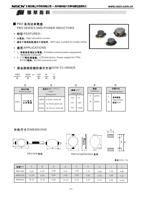
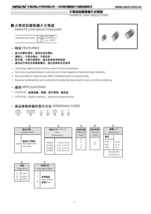
● FEATURES 特性Various high power inductors are superior to be high saturation for surface mounting. 具有高功率、高饱和电流、低阻抗、小型化之特性。
● APPLICATIONS 用途Power supply for TVR,OA equipment Digltal camera,LCD television set notebook PC, portable communicaton equipments,DC/DC converters,etc.录影机,OA 仪器,数码相机,液晶电视,笔记本电脑,小型通信设备,DC/DC 转换器。
● PART NUMBERING SYSTEM 品名系统● SHAPES AND DIMENSIONS 外形尺寸 (Unit:mm)TYPE(型号)A B C (Max) D (Max)E F G CKCD2D18 3.2±0.3 3.2±0.3 2.3 4.2 3.30.5 3.3CKCD3D16 3.8±0.5 3.8±0.5 2.1 5.5 4.3 1.0 4.3CKCD3D28 3.8±0.5 3.8±0.5 3.2 5.5 4.3 1.0 4.3CKCD4D18 4.7±0.5 4.7±0.5 2.1 6.9 5.3 1.5 5.3CKCD4D28 4.7±0.5 4.7±0.5 3.5 6.9 5.3 1.5 5.3CKCD5D18 5.7±0.5 5.7±0.5 2.28.2 6.3 2.0 6.3CKCD5D28 5.7±0.5 5.7±0.5 3.28.2 6.3 2.0 6.3CKCD6D28 6.7±0.5 6.7±0.5 3.29.57.3 2.07.3CKCD6D386.7±0.56.7±0.54.29.57.32.07.3M a r k i n g Recommended patternsFEGABD101CWA0B0K0D P AB C CKCD2D1812.0 3.3 3.3 2.5 1.58.0330100134000CKCD3D1612.0 4.2 4.2 2.4 1.58.0330100133000CKCD3D2812.0 4.2 4.2 3.5 1.58.0330100132000CKCD4D1812.0 5.4 5.4 2.5 1.58.0330100133000CKCD4D2812.0 5.5 5.5 3.8 1.58.0330100132000CKCD5D1816.0 6.1 6.1 2.5 1.58.0330100132000CKCD5D2816.0 6.1 6.1 3.2 1.58.0330100132000CKCD6D2816.07.27.2 3.5 1.512.0330100131500CKCD6D3816.07.67.6 4.5 1.512.0330100131000CKCD8D2824.08.49.3 3.5 1.512.0330100131500CKCD8D3824.08.49.3 5.2 1.512.0330100131000CKCD8D4324.08.49.3 5.2 1.512.0330100131000CKCD8D5824.08.49.36.01.512.033010013800Tape DimensionTypeReel DimensionQuantity (Pcs/Reel)●SPECIFICATION TABLE:PART NUMBER品名INDUCTANCE(μH)电感值DCR (Max)(Ω)直流电阻IDC (Max)(A)额定电流TEST FREQ(kHz)测试频率CKCD2D18-2.2uH/N 2.2±30%0.11 1.10100CKCD2D18-3.3uH/N 3.3±30%0.12 1.00100CKCD2D18-4.7uH/N 4.7±30%0.160.90100CKCD2D18-6.8uH/N 6.8±30%0.230.58100CKCD2D18-10uH/M 10±20%0.320.50100CKCD2D18-22uH/M 22±20%0.700.24100CKCD2D18-47uH/M 47±20% 1.300.22100CKCD2D18-100uH/M100±20%3.50.17100● SPECIFICATION TABLE:PART NUMBER品名INDUCTANCE(μH)电感值DCR (Max)(Ω)直流电阻IDC (Max)(A)额定电流TEST FREQ(kHz)测试频率CKCD3D16-1.5uH/N 1.5±30%0.075 1.30100CKCD3D16-2.2uH/N 2.2±30%0.100 1.20100CKCD3D16-3.3uH/N 3.3±30%0.140 1.00100CKCD3D16-4.7uH/N 4.7±30%0.1500.90100CKCD3D16-5.6uH/N 5.6±30%0.1600.83100CKCD3D16-6.8uH/N 6.8±30%0.1700.73100CKCD3D16-10uH/M 10±20%0.2000.60100CKCD3D16-15uH/M 15±20%0.4500.45100CKCD3D16-22uH/M 22±20%0.5000.40100CKCD3D16-47uH/M 47±20% 1.2000.30100CKCD3D16-100uH/M 100±20% 1.8300.10100CKCD3D16-470uH/M470±20%9.2000.08100Remark: ● Inductance Tested at 100kHz,0.25Vrms (20℃)● IDC: DC current at which the inductance drops approximate 20% from its value without current ● Operating Temperature : -25℃ ~ +105℃ ● Measure Equipment:INDUCTANCE : Agilent HP-4284A , HP-4285A IDC : Agilent HP-4284A+HP-42841A DCR : CHEN HWA 502A●SPECIFICATION TABLE:PART NUMBER品名INDUCTANCE(μH)电感值DCR (Max)(Ω)直流电阻IDC (Max)(A)额定电流TEST FREQ(kHz)测试频率CKCD3D28-2.2uH/N 2.2±30%0.075 1.80100CKCD3D28-3.3uH/N 3.3±30%0.096 1.50100CKCD3D28-4.7uH/M 4.7±20%0.110 1.20100CKCD3D28-6.8uH/M 6.8±20%0.130 1.00100CKCD3D28-10uH/M 10±20%0.2100.90100CKCD3D28-22uH/M 22±20%0.2800.60100CKCD3D28-33uHM 33±20%0.3500.36100CKCD3D28-39uH/M 39±20%0.7000.20100CKCD3D28-100uH/M 100±20%0.9300.16100CKCD3D28-220uH/M220±20%2.6000.14100● SPECIFICATION TABLE:PART NUMBER品名INDUCTANCE(μH)电感值DCR (Max)(Ω)直流电阻IDC (Max)(A)额定电流TEST FREQ(kHz)测试频率CKCD4D18-1.0uH/N 1.0±30%0.050 2.00100CKCD4D18-1.5uH/N 1.5±30%0.058 1.80100CKCD4D18-2.2uH/N 2.2±30%0.070 1.50100CKCD4D18-3.3uH/N 3.3±30%0.110 1.00100CKCD4D18-4.7uH/M 4.7±20%0.1200.80100CKCD4D18-6.8uH/M 6.8±20%0.1620.70100CKCD4D18-10uH/M 10±20%0.1800.65100CKCD4D18-15uH/M 15±20%0.2900.60100CKCD4D18-22uH/M 22±20%0.4500.50100CKCD4D18-33uH/M 33±20%0.6800.40100CKCD4D18-47uH/M 47±20%0.9500.30100CKCD4D18-100uH/M 100±20% 2.2000.20100CKCD4D18-220uH/M 220±20% 4.0000.15100CKCD4D18-470uH/M470±20%7.3000.12100Remark: ● Inductance Tested at 100kHz,0.25Vrms (20℃)● IDC: DC current at which the inductance drops approximate 20% from its value without current ● Operating Temperature : -25℃ ~ +105℃ ● Measure Equipment:INDUCTANCE : Agilent HP-4284A , HP-4285A IDC : Agilent HP-4284A+HP-42841A● SPECIFICATION TABLE:PART NUMBER品名INDUCTANCE(μH)电感值DCR (Max)(Ω)直流电阻IDC (Max)(A)额定电流TEST FREQ(kHz)测试频率CKCD4D28-1.0uH/N 1.0±30%0.030 2.40100 CKCD4D28-1.2uH/N 1.2±30%0.035 2.20100 CKCD4D28-1.5uH/N 1.5±30%0.040 2.10100 CKCD4D28-1.8uH/N 1.8±30%0.045 2.00100 CKCD4D28-2.2uH/M 2.2±20%0.050 1.80100 CKCD4D28-3.3uH/M 3.3±20%0.060 1.60100 CKCD4D28-4.7uH/M 4.7±20%0.065 1.50100 CKCD4D28-6.8uH/M 6.8±20%0.080 1.10100 CKCD4D28-10uH/M10±20%0.1300.90100 CKCD4D28-22uH/M22±20%0.2200.60100 CKCD4D28-33uH/M33±20%0.3500.50100 CKCD4D28-47uH/M47±20%0.4500.40100 CKCD4D28-56uH/M56±20%0.4800.38100 CKCD4D28-68uH/M68±20%0.7000.35100 CKCD4D28-100uH/M100±20%0.9000.30100 CKCD4D28-150uH/M150±20% 1.2000.20100 CKCD4D28-180uH/M180±20% 1.3000.18100 CKCD4D28-220uH/M220±20% 1.8000.15100 CKCD4D28-300uHM330±20% 2.3000.05100Remark: ●Inductance Tested at 100kHz,0.25Vrms (20℃)● IDC: DC current at which the inductance drops approximate 20% from its value without current● Operating Temperature : -25℃ ~ +105℃● Measure Equipment:INDUCTANCE : Agilent HP-4284A , HP-4285AIDC : Agilent HP-4284A+HP-42841ADCR : CHEN HWA 502A●SPECIFICATION TABLE:PART NUMBER品名INDUCTANCE(μH)电感值DCR (Max)(Ω)直流电阻IDC (Max)(A)额定电流TEST FREQ(kHz)测试频率CKCD5D18-0.9uH/N 0.9±30%0.040 2.30100CKCD5D18-1.8uH/N 1.8±30%0.045 2.00100CKCD5D18-2.2uH/N 2.2±30%0.060 1.80100CKCD5D18-3.3uH/N 3.3±30%0.065 1.50100CKCD5D18-4.1uH/N 4.1±30%0.075 1.30100CKCD5D18-4.7uH/M 4.7±20%0.080 1.00100CKCD5D18-6.8uH/M 6.8±20%0.1400.90100CKCD5D18-10uH/M 10±20%0.1600.80100CKCD5D18-15uH/M 15±20%0.2000.60100CKCD5D18-22uH/M 22±20%0.3000.58100CKCD5D18-33uH/M33±20%0.5100.55100● SPECIFICATION TABLE:PART NUMBER品名INDUCTANCE(μH)电感值DCR (Max)(Ω)直流电阻IDC (Max)(A)额定电流TEST FREQ(kHz)测试频率CKCD5D28-1.8uH/N 1.5±30%0.030 2.20100CKCD5D28-2.2uH/N 2.2±30%0.035 2.00100CKCD5D28-3.3uH/N 3.3±30%0.060 1.90100CKCD5D28-4.7uH/M 4.7±20%0.065 1.50100CKCD5D28-6.2uH/M 6.2±20%0.070 1.30100CKCD5D28-6.8uH/M 6.8±20%0.075 1.25100CKCD5D28-8.2uH/M 8.2±20%0.085 1.20100CKCD5D28-10uH/M 10±20%0.090 1.00100CKCD5D28-15uH/M 15±20%0.1100.80100CKCD5D28-18uH/M 18±20%0.1500.75100CKCD5D28-22uH/M 22±20%0.1700.70100CKCD5D28-33uH/M 33±20%0.2650.50100CKCD5D28-47uH/M 47±20%0.3000.45100CKCD5D28-68uH/M 68±20%0.6000.40100CKCD5D28-100uH/M 100±20%0.7000.30100CKCD5D28-120uH/M 120±20%0.8000.25100●SPECIFICATION TABLE:PART NUMBER品名INDUCTANCE(μH)电感值DCR (Max)(Ω)直流电阻IDC (Max)(A)额定电流TEST FREQ(kHz)测试频率CKCD6D28-1.5uH/N 1.5±30%0.038 3.00100CKCD6D28-2.2uH/N 2.2±30%0.040 2.80100CKCD6D28-3.3uH/N 3.3±30%0.045 2.20100CKCD6D28-4.7uH/M 4.7±20%0.060 1.80100CKCD6D28-6.8uH/M 6.8±20%0.070 1.50100CKCD6D28-10uH/M 10±20%0.080 1.30100CKCD6D28-15uH/M 15±20%0.1100.90100CKCD6D28-22uH/M 22±20%0.1450.80100CKCD6D28-33uH/M 33±20%0.2200.60100CKCD6D28-47uH/M 47±20%0.2700.50100CKCD6D28-100uH/M 100±20%0.7000.40100CKCD6D28-150uH/M150±20%0.9500.38100● SPECIFICATION TABLE:PART NUMBER品名INDUCTANCE(μH)电感值DCR (Max)(Ω)直流电阻IDC (Max)(A)额定电流TEST FREQ(kHz)测试频率CKCD6D38-2.2uH/N 2.2±30%0.033 3.00100CKCD6D38-3.3uH/N 3.3±30%0.035 2.80100CKCD6D38-4.7uH/M 4.7±20%0.040 2.30100CKCD6D38-6.8uH/N 6.8±30%0.050 2.00100CKCD6D38-10uH/M 10±20%0.070 1.80100CKCD6D38-15uH/M 15±20%0.105 1.50100CKCD6D38-18uH/M 18±20%0.120 1.40100CKCD6D38-22uH/M 22±20%0.160 1.30100CKCD6D38-33uH/M 33±20%0.170 1.00100CKCD6D38-47uH/M 47±20%0.2500.90100CKCD6D38-56uH/M 56±20%0.2600.85100CKCD6D38-68uH/M 68±20%0.2700.60100CKCD6D38-82uH/M 82±20%0.3000.45100CKCD6D38-100uH/M 100±20%0.4000.40100CKCD6D38-150uH/M 150±20%0.8500.35100CKCD6D38-220uH/M 220±20% 1.0500.30100CKCD6D38-330uH/M 330±20% 1.600.20100CKCD6D38-470uH/M 470±20% 2.500.25100● FEATURES 特性Various high power inductors are superior to be high saturation for surface mounting. 具有高功率、高饱和电流、低阻抗、小型化之特性。
1000uh 阻值摘要:一、1000uh阻值的含义1.1000uh是什么2.阻值的定义和单位二、1000uh阻值的应用领域1.通信行业2.电源行业3.电子元器件行业三、1000uh阻值的选型与使用1.选型考虑因素a.额定电压b.额定电流c.温度系数2.使用注意事项a.安装b.接线c.测量与测试四、1000uh阻值的发展趋势与展望1.新材料的研究与应用2.新型结构的设计与实现3.市场前景与需求分析正文:一、1000uh阻值的含义1000uh是一种电感元件的阻值表示方法,通常用于通信、电源和电子元器件等领域。
阻值是指电感元件对电流的阻碍程度,单位为欧姆(Ω)。
1000uh阻值表示该电感元件的电感值为1000欧姆。
2.阻值的定义和单位阻值是指导体对电流的阻碍程度。
它是指导体通过电流时产生的电压降。
在国际单位制中,阻值的单位为欧姆(Ω)。
二、1000uh阻值的应用领域1.通信行业在通信行业中,1000uh阻值通常用于滤波器、耦合器等元器件,以实现信号的传输与处理。
2.电源行业在电源行业中,1000uh阻值广泛应用于变压器、电感等元器件,以实现电源的转换与滤波等功能。
3.电子元器件行业在电子元器件行业中,1000uh阻值可用于各种类型的电感元件,满足不同应用场景的需求。
三、1000uh阻值的选型与使用1.选型考虑因素a.额定电压:根据实际工作电压选择合适的1000uh阻值电感元件。
b.额定电流:根据电路中的电流大小选择合适的额定电流值。
c.温度系数:电感元件的阻值随温度的变化而变化,需要考虑温度系数以保证元件在不同环境下的性能稳定。
2.使用注意事项a.安装:在安装过程中,确保电感元件与电路板之间的接触良好,避免虚接、短路等现象。
b.接线:按照电路图要求正确连接电源、信号等线路,注意接线顺序与极性。
c.测量与测试:使用合适的测量仪器对电感元件进行测量与测试,确保其性能满足设计要求。
四、1000uh阻值的发展趋势与展望1.新材料的研究与应用:随着新材料的不断研究与发展,未来可能出现具有更高性能的1000uh阻值电感元件。